WO2011078327A1 - Rotary blade of windmill and method of manufacturing rotary blade of windmill - Google Patents
Rotary blade of windmill and method of manufacturing rotary blade of windmill Download PDFInfo
- Publication number
- WO2011078327A1 WO2011078327A1 PCT/JP2010/073349 JP2010073349W WO2011078327A1 WO 2011078327 A1 WO2011078327 A1 WO 2011078327A1 JP 2010073349 W JP2010073349 W JP 2010073349W WO 2011078327 A1 WO2011078327 A1 WO 2011078327A1
- Authority
- WO
- WIPO (PCT)
- Prior art keywords
- girder
- wind turbine
- turbine rotor
- disposed
- blade
- Prior art date
Links
- 238000004519 manufacturing process Methods 0.000 title claims description 43
- 229920002430 Fibre-reinforced plastic Polymers 0.000 claims abstract description 7
- 239000011151 fibre-reinforced plastic Substances 0.000 claims abstract description 7
- 239000000463 material Substances 0.000 claims description 142
- 239000012783 reinforcing fiber Substances 0.000 claims description 23
- 238000010248 power generation Methods 0.000 claims description 8
- 238000000034 method Methods 0.000 claims description 5
- 238000009415 formwork Methods 0.000 claims description 3
- 238000010030 laminating Methods 0.000 claims description 2
- 210000001015 abdomen Anatomy 0.000 claims 1
- 239000000835 fiber Substances 0.000 abstract description 7
- 230000003014 reinforcing effect Effects 0.000 abstract 3
- 239000002699 waste material Substances 0.000 description 7
- 230000003511 endothelial effect Effects 0.000 description 6
- 239000000853 adhesive Substances 0.000 description 3
- 239000011257 shell material Substances 0.000 description 3
- 229920000049 Carbon (fiber) Polymers 0.000 description 2
- 240000007182 Ochroma pyramidale Species 0.000 description 2
- 230000001070 adhesive effect Effects 0.000 description 2
- 239000004917 carbon fiber Substances 0.000 description 2
- 239000011162 core material Substances 0.000 description 2
- 238000005520 cutting process Methods 0.000 description 2
- 230000007423 decrease Effects 0.000 description 2
- 230000000694 effects Effects 0.000 description 2
- 239000006260 foam Substances 0.000 description 2
- 239000003365 glass fiber Substances 0.000 description 2
- VNWKTOKETHGBQD-UHFFFAOYSA-N methane Chemical compound C VNWKTOKETHGBQD-UHFFFAOYSA-N 0.000 description 2
- 238000012986 modification Methods 0.000 description 2
- 230000004048 modification Effects 0.000 description 2
- 239000002994 raw material Substances 0.000 description 2
- 239000011347 resin Substances 0.000 description 2
- 229920005989 resin Polymers 0.000 description 2
- 239000002023 wood Substances 0.000 description 2
- 239000002759 woven fabric Substances 0.000 description 2
- 235000018936 Vitellaria paradoxa Nutrition 0.000 description 1
- 238000004026 adhesive bonding Methods 0.000 description 1
- 238000005452 bending Methods 0.000 description 1
- 230000007613 environmental effect Effects 0.000 description 1
- 230000002787 reinforcement Effects 0.000 description 1
Images


Classifications
-
- F—MECHANICAL ENGINEERING; LIGHTING; HEATING; WEAPONS; BLASTING
- F03—MACHINES OR ENGINES FOR LIQUIDS; WIND, SPRING, OR WEIGHT MOTORS; PRODUCING MECHANICAL POWER OR A REACTIVE PROPULSIVE THRUST, NOT OTHERWISE PROVIDED FOR
- F03D—WIND MOTORS
- F03D1/00—Wind motors with rotation axis substantially parallel to the air flow entering the rotor
- F03D1/06—Rotors
- F03D1/065—Rotors characterised by their construction elements
- F03D1/0675—Rotors characterised by their construction elements of the blades
-
- B—PERFORMING OPERATIONS; TRANSPORTING
- B29—WORKING OF PLASTICS; WORKING OF SUBSTANCES IN A PLASTIC STATE IN GENERAL
- B29L—INDEXING SCHEME ASSOCIATED WITH SUBCLASS B29C, RELATING TO PARTICULAR ARTICLES
- B29L2031/00—Other particular articles
- B29L2031/08—Blades for rotors, stators, fans, turbines or the like, e.g. screw propellers
- B29L2031/082—Blades, e.g. for helicopters
- B29L2031/085—Wind turbine blades
-
- Y—GENERAL TAGGING OF NEW TECHNOLOGICAL DEVELOPMENTS; GENERAL TAGGING OF CROSS-SECTIONAL TECHNOLOGIES SPANNING OVER SEVERAL SECTIONS OF THE IPC; TECHNICAL SUBJECTS COVERED BY FORMER USPC CROSS-REFERENCE ART COLLECTIONS [XRACs] AND DIGESTS
- Y02—TECHNOLOGIES OR APPLICATIONS FOR MITIGATION OR ADAPTATION AGAINST CLIMATE CHANGE
- Y02E—REDUCTION OF GREENHOUSE GAS [GHG] EMISSIONS, RELATED TO ENERGY GENERATION, TRANSMISSION OR DISTRIBUTION
- Y02E10/00—Energy generation through renewable energy sources
- Y02E10/70—Wind energy
- Y02E10/72—Wind turbines with rotation axis in wind direction
-
- Y—GENERAL TAGGING OF NEW TECHNOLOGICAL DEVELOPMENTS; GENERAL TAGGING OF CROSS-SECTIONAL TECHNOLOGIES SPANNING OVER SEVERAL SECTIONS OF THE IPC; TECHNICAL SUBJECTS COVERED BY FORMER USPC CROSS-REFERENCE ART COLLECTIONS [XRACs] AND DIGESTS
- Y02—TECHNOLOGIES OR APPLICATIONS FOR MITIGATION OR ADAPTATION AGAINST CLIMATE CHANGE
- Y02P—CLIMATE CHANGE MITIGATION TECHNOLOGIES IN THE PRODUCTION OR PROCESSING OF GOODS
- Y02P70/00—Climate change mitigation technologies in the production process for final industrial or consumer products
- Y02P70/50—Manufacturing or production processes characterised by the final manufactured product
-
- Y—GENERAL TAGGING OF NEW TECHNOLOGICAL DEVELOPMENTS; GENERAL TAGGING OF CROSS-SECTIONAL TECHNOLOGIES SPANNING OVER SEVERAL SECTIONS OF THE IPC; TECHNICAL SUBJECTS COVERED BY FORMER USPC CROSS-REFERENCE ART COLLECTIONS [XRACs] AND DIGESTS
- Y10—TECHNICAL SUBJECTS COVERED BY FORMER USPC
- Y10T—TECHNICAL SUBJECTS COVERED BY FORMER US CLASSIFICATION
- Y10T156/00—Adhesive bonding and miscellaneous chemical manufacture
- Y10T156/10—Methods of surface bonding and/or assembly therefor
- Y10T156/1002—Methods of surface bonding and/or assembly therefor with permanent bending or reshaping or surface deformation of self sustaining lamina
- Y10T156/1028—Methods of surface bonding and/or assembly therefor with permanent bending or reshaping or surface deformation of self sustaining lamina by bending, drawing or stretch forming sheet to assume shape of configured lamina while in contact therewith
- Y10T156/103—Encasing or enveloping the configured lamina
Definitions
- the present invention relates to a wind turbine rotor that constitutes a wind turbine for wind power generation and a method of manufacturing the wind turbine rotor.
- Patent Document 1 As a wind turbine rotor, for example, the one disclosed in Patent Document 1 is known.
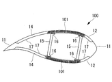
- the wind turbine rotor 100 is provided with a shell 11, a leading edge sandwich 12, a main strength material (spar cap material) 101, a trailing edge sandwich 14, a shear web (girder) 15, and an endothelial material 17.
- the front edge sandwich material 12 and the rear edge sandwich material 14 have a sandwich structure in which the skin material 11 and the endothelial material 17 are used as a skin material, and a foam of resin such as PVC or wood such as balsa is used as a core material.
- symbol 16 in FIG. 7 is an adhesive agent which connects the main strength material 101 and the shear web 15 (connection).
- the reinforcement of a certain width delivered from the fiber manufacturer is made in accordance with the planar view shape (the outer shape and the dimensions of each member) of the wind turbine rotor 100 changing in the blade longitudinal direction.
- a plurality of sheets whose width changes in the longitudinal direction are cut out of a fiber sheet (eg, glass fiber woven fabric, glass fiber prepreg, carbon fiber woven fabric, carbon fiber prepreg), and the cut out plurality of sheets are mainly stacked.
- the strength material 101 is produced. Therefore, there is a problem that the material which has been cut off is wasted and the manufacturing cost is increased.
- the present invention has been made in view of the above-mentioned circumstances, and can eliminate the waste of the material at the time of producing the main strength material (spar cap material), and can reduce the manufacturing cost, and a windmill
- An object of the present invention is to provide a method of manufacturing a rotary wing.
- a wind turbine rotor including: an outer cover made of fiber reinforced plastic; a main strength member disposed on the back and ventral inner surface of the outer cover; and the main strength members
- the main strength material is formed by stacking reinforcing fiber sheets of a certain width in the longitudinal direction.
- the main strength material is formed (constructed) simply by stacking reinforcing fiber sheets of a certain width delivered from a fiber manufacturer.
- the waste of the raw material at the time of doing can be eliminated, and a manufacturing cost can be reduced.
- the number of laminated reinforcing fiber sheets constituting the main strength material is selected according to the strength required at the position in the radial direction of rotation of the wind turbine rotor blade. .
- the distance between the girder material disposed on the leading edge side of the girder material and the girder material disposed on the trailing edge side is kept constant from the root side to the tip side of the wing. It is further preferable that the girder material is disposed. In the above-mentioned wind turbine rotor, the distance between the girder material disposed on the leading edge side and the girder material disposed on the trailing edge side of the girder material gradually and linearly from the root side to the tip side of the blade. It is further preferable that the girder members be disposed so as to be extremely narrow.
- the root side of the wing refers to one end side of the wing attached to the rotor head
- the “tip side of the wing” refers to the other wing that becomes a free end when attached to the rotor head. It is the end side.
- a wind turbine rotor According to such a wind turbine rotor, it has conventionally been disposed on the leading edge side which has been nonlinearly changed from the root side to the tip side of the wing in consideration of the width of the wind turbine rotor (which changes in the blade longitudinal direction)
- the distance between the girder and the girder arranged on the trailing edge can be constant or linear change, and the girder is specially designed for fixing (gluing) the girder to the main strength material, called gantry. Since the positioning operation at the time of fixing to the tool is performed easily and promptly, the time required for the manufacturing operation can be shortened, and the productivity can be improved.
- the girder material is disposed without being twisted from the root side to the tip side of the wing.
- the girder material is also from the root side of the blade although it was made into the shape twisted toward the tip side, since the twist of this girder material becomes unnecessary, the manufacturing cost of the mold used when manufacturing girder material can be reduced, and the girder material is more than conventional It can be easily and rapidly produced.
- “torsion” refers to “twisting up” in which the angle of attack on the wind turbine rotor gradually increases as it goes to the tip of the wing (tip) or the angle of attack on the wind turbine rotor to the tip of the wing (tip) It is the “twisting down” which decreases gradually according to.
- positioning work for fixing the girder material to a special jig called a gantry for attaching (adhering) girder material to the main strength material is performed more easily and quickly. The time required for the manufacturing operation can be further shortened, and the productivity can be further improved.
- the wind turbine for wind power generation according to the second aspect of the present invention is equipped with a wind turbine rotor that can eliminate waste of the material when producing the main strength material and can reduce the manufacturing cost.
- the wind turbine for wind power generation according to the second aspect of the present invention, it is possible to contribute to global environmental problems and to reduce the manufacturing cost.
- a method of manufacturing a wind turbine rotor comprising: a shell made of fiber reinforced plastic; A method of manufacturing a wind turbine rotor blade having a girder member disposed between strength members, the method comprising: stacking reinforcing fiber sheets of a certain width in a longitudinal direction to produce the main strength member; The outer covering material which forms the surface of the back side is placed on the 1st formwork which forms the above, and the main strength material placed on the back side of the girder material is placed on the outer covering material And an outer covering material forming an outer surface of the girder is placed on a second formwork for forming a half-split wing on an outer side, and And a step of mounting the main strength material to be disposed.
- a reinforcing fiber sheet of a certain width supplied from a fiber manufacturer is cut in accordance with the longitudinal change of the plan view shape of the wind turbine rotor. Since the main strength material is formed (constructed) simply by stacking, waste of the material at the time of producing the main strength material can be eliminated, and the manufacturing cost can be reduced.
- the distance between the girder material disposed on the leading edge side of the girder material and the girder material disposed on the trailing edge side is kept constant from the root side to the tip side of the wing. It is further preferred that the girder material is arranged in this way. Further, in the method of manufacturing a wind turbine rotor, the distance between the girder material disposed on the leading edge side of the girder material and the girder material disposed on the trailing edge side gradually increases from the root side to the tip side of the wing. Further, it is more preferable that the girder members be disposed so as to be linearly narrowed.
- the distance between the girder material disposed on the leading edge side and the girder material disposed on the trailing edge side is considered in consideration of the width of the wind turbine rotor blade. Since it is not necessary to change from the root side to the tip side of the wing, the positioning operation when fixing the girder material to a dedicated jig called gantry, for attaching (adhering) girder material to the main strength material, Since the process is performed easily and promptly, the time required for the manufacturing operation can be shortened, and the productivity can be improved.
- the girder material is manufactured without being twisted from the root side to the tip side of the wing.
- a method of manufacturing a wind turbine rotor when manufacturing the girder material, it is not necessary to twist the girder material from the root side to the tip side of the blade in consideration of the twist of the wind turbine rotor blade.
- the manufacturing cost of the mold used when manufacturing can be reduced, and the girder material can be manufactured more easily and rapidly.
- positioning work for fixing the girder material to a special jig called a gantry for attaching (adhering) girder material to the main strength material is performed more easily and quickly.
- the time required for the manufacturing operation can be further shortened, and the productivity can be further improved.
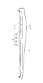
- FIG. 1 It is a side view showing a wind turbine for wind power generation provided with a wind turbine rotor blade concerning a 1st embodiment of the present invention.
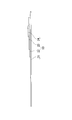
- It is a top view of a windmill rotor concerning a 1st embodiment of the present invention.
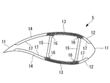
- It is a BB arrow sectional view of FIG.
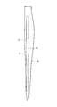
- It is a top view of a windmill rotor concerning a 2nd embodiment of the present invention.
- FIG. 1 is a side view showing a wind turbine for wind power generation equipped with a wind turbine rotor according to the present embodiment
- FIG. 2 is a plan view of the wind turbine rotor according to the present embodiment
- FIG. FIG. 4 is a cross-sectional view taken along the line BB in FIG.
- the twisting up from the blade root (root) to the blade tip (tip) of the wind turbine rotor (the angle of attack gradually increases from the blade root to the blade tip
- the wing twist is not considered (shown).
- only the spar cap material located in the back side is shown in FIG.
- the wind turbine 1 for wind power generation has a substantially horizontal axis line with a support (also referred to as “tower”) 2 erected on a foundation B and a nacelle 3 installed at the upper end of the support 2. It has a rotor head 4 rotatably provided around the nacelle 3. A plurality of (for example, three) wind turbine rotors 5 are attached to the rotor head 4 radially around the rotation axis. As a result, the force of the wind that hits the wind turbine rotor 5 from the direction of the rotational axis of the rotor head 4 is converted into the motive power that causes the rotor head 4 to rotate around the rotational axis.
- the support 2 is configured such that a plurality of (for example, three) units (not shown) are vertically connected.
- the nacelle 3 is installed on the unit provided at the top among the units constituting the column 2, and the nacelle base plate (not shown) attached to the upper end of the column 2 and the nacelle base plate And a cover 6 covering from above.
- the wind turbine rotor 5 has a spar cap structure that meets the requirements of both lightness and strength, and the skin material 11, the leading edge sandwich material 12, and the spar cap material (main strength material And 13), a trailing edge sandwich material 14, a shear web 15 and an endothelial material 17.
- the outer covering material 11, the spar cap material 13 and the endothelial material 17 are each formed (configured) of fiber reinforced plastic (FRP).
- the spar cap member 13 is a member in which reinforcing fiber sheets are laminated in multiple layers, and provided one on each of the back side (upper side in FIG. 3) and the ventral side (lower side in FIG. 3) of the wind turbine rotor 5 . Further, the spar cap material 13 and the shear web 15 are connected (connected) via an adhesive 16 which is cured at normal temperature.
- Each of the front edge sandwich material 12 and the rear edge sandwich material 14 has a sandwich structure in which the outer skin material 11 and the endothelial material 17 are used as a skin material, a foam of resin such as PVC, and wood such as balsa as a core material There is. And in such a spar cap structure, bending strength in the flap direction of the wind turbine rotor 5 is maintained mainly by the spar cap material 13 which is a member obtained by laminating reinforcing fiber sheets in multiple layers, and the leading edge sandwich material 12 and the trailing edge The sandwich material 14 is additionally used to maintain the buckling strength of the wind turbine rotor 5.
- the wind turbine rotor 5 is provided with, for example, a spar cap material 13 as shown in FIGS. 2 and 4.
- the spar cap material 13 has a constant width (length in the cord direction (vertical direction in FIG. 2)) from the root side to the tip side of the wing as shown in FIG. 2, and as shown in FIG.
- the reinforcing fiber sheets 21, 22, 23, 24 having different lengths in the direction (the left and right direction in FIG. 2) are members laminated as shown in FIG. 2 and FIG. That is, the spar cap material 13 is in a state in which all the reinforcing fiber sheets 21, 22, 23, 24 are laminated at a certain position (generally 40 to 60% rotational radius position) of the wind turbine rotor 5 in the longitudinal direction.
- the reinforcing fiber sheets 21, 22, 23, 24 are formed so as to gradually decrease in number from the position where the number of laminated sheets is maximum to the root side and the tip side of the wing.
- the number of laminated reinforcing fiber sheets 21, 22, 23, 24 is selected in accordance with the strength required at the radial position of the wind turbine rotor.
- the reinforcing fiber sheets 21, 22, 23, 24 are formed to have the same width and the same thickness. Further, in the shear web 15, the distance between the shear web 15 disposed on the leading edge side and the shear web 15 disposed on the trailing edge changes in consideration of the width of the wind turbine rotor 5, that is, from the root side to the tip side of the wing. It is made proportional to the length in the direction of the cord and twisted in accordance with a predetermined twisting set up from the blade root to the blade tip.
- the spar cap material is obtained by simply stacking the reinforcing fiber sheets of a certain width supplied from the fiber manufacturer without cutting them in accordance with the plan view shape of the wind turbine rotor 5. Since 13 is formed (constructed), it is possible to eliminate the waste of the material when producing the spar cap material 13 and to reduce the manufacturing cost.
- the number of laminated reinforcing fiber sheets 21, 22, 23, 24 constituting the spar cap material 13 is selected in accordance with the strength required at the position in the rotation radial direction of the wind turbine rotor. As a result, the necessary strength as the spar cap material 13 is secured, so that brittle fracture, fatigue fracture and buckling of the spar cap material 13 with respect to a load in the flap direction (dorsal-facing direction) can be prevented.
- the covering material 11 for forming the back surface is placed on the first form (not shown) for forming the half-split wing, and disposed on the covering material 11 on the back side of the shear web 15 Mounting the outer cap material 13 forming the surface on the ventral side on the second mold (not shown) for forming the half-split wing on the ventral side.
- a reinforcing fiber sheet of a certain width delivered from a fiber manufacturer is cut at a desired length without cutting in accordance with the width (length in the cord direction) of the wind turbine rotor 5, and these are simply cut. Since the spar cap material 13 is formed (constructed) by stacking, waste of the material at the time of producing the spar cap material 13 can be eliminated, and the manufacturing cost can be reduced.
- FIG. 5 is a plan view of a wind turbine rotor according to the present embodiment.
- twisting up from the blade root (root) to the blade tip (tip) of the wind turbine rotor blade Is not considered (shown).
- the wind turbine rotor 30 according to the present embodiment differs from that of the first embodiment described above in that it includes a shear web 31 instead of the shear web 15.
- the other components are the same as those of the above-described first embodiment, and thus the description of those components is omitted here.
- symbol is attached
- the distance between the shear webs 31 (the distance between the shear web 31 located on the front edge side and the shear web 31 located on the rear edge side) is constant from the root side to the tip side of the wing.
- the shear web 31 is disposed in such a manner as to be maintained.
- the shear web 31 is twisted in accordance with a predetermined twisting set from the root side to the tip side of the blade of the wind turbine rotor 30.
- the width of the wind turbine rotor (which changes in the blade longitudinal direction) is taken into account in the prior art. Since the distance between the shear web 31 disposed on the leading edge side and the shear web 31 disposed on the trailing edge side can be made constant, the shear web 31 can be attached (bonded) to the spar cap member 13 Since the positioning operation at the time of fixing the shear web 31 to a dedicated jig (not shown) called a gantry is performed easily and promptly, the time required for the manufacturing operation can be shortened. Productivity can be improved. The other operational effects are the same as those of the first embodiment described above, and thus the description thereof is omitted here.
- FIG. 6 is a plan view of a wind turbine rotor blade according to the present embodiment.
- twisting up from the blade root (root) to the blade tip (tip) of the wind turbine rotor blade Is not considered (shown).
- the wind turbine rotor 40 according to the present embodiment differs from that of the first embodiment described above in that it includes a shear web 41 instead of the shear web 15.
- the other components are the same as those of the above-described first embodiment, and thus the description of those components is omitted here.
- symbol is attached
- the distance between the shear web 41 gradually increases from the root side to the tip side of the wing.
- the shear web 41 is disposed so that it narrows linearly, that is, the shape of the shear web 41 in a plan view tapers from the root side to the tip side of the wing. Further, the shear web 41 is twisted in accordance with a predetermined twisting set from the root side to the tip side of the blade of the wind turbine rotor 40.
- the width of the wind turbine rotor (which changes in the blade longitudinal direction) is taken into account and nonlinear from the root side to the tip side of the wing Since the distance between the sheared web 41 disposed on the leading edge side and the sheared web 41 disposed on the trailing edge side can be changed linearly, the shea web 41 is attached (bonded) to the spar cap member 13 Since the positioning operation when fixing the shear web 41 to a dedicated jig (not shown) called a gantry is performed easily and promptly, the time required for the manufacturing operation can be shortened. , Can improve productivity.
- the other operational effects are the same as those of the first embodiment described above, and thus the description thereof is omitted here.
- the shear webs 31 and 41 are not twisted from the root side to the tip side of the blades of the wind turbine rotors 30 and 40, and the outer shape maintains the planar shape. It is more preferable to be disposed (housed) inside the outer cover material 11.
- the shear webs 31 and 41 are manufactured, the shear webs 31 and 41 are twisted by lowering the wind turbine rotors 30 and 40 by arranging the shear webs 31 and 41 by arranging the shear webs 31 and 41 in the interior of the outer covering 11 while maintaining the planar shape.
- Wind turbine for wind power generation 2 pillar (tower) 3 nacelle 4 rotor head 5 windmill rotor blade 6 nacelle cover 11 shell material 12 leading edge sandwich material 13 spar cap material (main strength material) 14 trailing edge sandwich material 15 shear web (beam material) 16 Adhesive 17 Endothelial material 21 Reinforcing fiber sheet 22 Reinforcing fiber sheet 23 Reinforcing fiber sheet 24 Reinforcing fiber sheet 30 Wind turbine rotor blade 31 Shear web 40 Wind turbine rotor blade 41 Shear web B Foundation
Abstract
Description
なお、図7中の符号16は、主強度材101とシアウェブ15とを接続(連結)する接着剤である。 Further, as shown in FIG. 7, in recent years, a
In addition, the code |
本発明の第一の態様に係る風車回転翼は、繊維強化プラスチックで形成された外皮材と、該外皮材の背側および腹側の内面に配置された主強度材と、該主強度材間に配置された桁材とを有する風車回転翼であって、前記主強度材は、長手方向に一定幅の強化繊維シートが積み重ねられて形成されている。 The present invention adopts the following means in order to solve the above problems.
According to a first aspect of the present invention, there is provided a wind turbine rotor including: an outer cover made of fiber reinforced plastic; a main strength member disposed on the back and ventral inner surface of the outer cover; and the main strength members The main strength material is formed by stacking reinforcing fiber sheets of a certain width in the longitudinal direction.
また、上記風車回転翼において、前記桁材を構成する前縁側に配置された桁材と後縁側に配置された桁材との間隔が、翼の根元側から先端側にかけて徐々に、かつ、線形的に狭くなるようにして前記桁材が配置されているとさらに好適である。
ここで、「翼の根元側」とは、ローターヘッドに取り付けられる翼の一端側のことであり、「翼の先端側」とは、ローターヘッドに取り付けられた際に自由端となる翼の他端側のことである。 In the above-described wind turbine rotor, the distance between the girder material disposed on the leading edge side of the girder material and the girder material disposed on the trailing edge side is kept constant from the root side to the tip side of the wing. It is further preferable that the girder material is disposed.
In the above-mentioned wind turbine rotor, the distance between the girder material disposed on the leading edge side and the girder material disposed on the trailing edge side of the girder material gradually and linearly from the root side to the tip side of the blade. It is further preferable that the girder members be disposed so as to be extremely narrow.
Here, "the root side of the wing" refers to one end side of the wing attached to the rotor head, and the "tip side of the wing" refers to the other wing that becomes a free end when attached to the rotor head. It is the end side.
ここで、「ねじり」とは、風車回転翼における迎え角を翼の先端(翼端)に行くに従い次第に増加させる「捩り上げ」または風車回転翼における迎え角を翼の先端(翼端)に行くに従い次第に減少させる「捩り下げ」のことである。
また、桁材を主強度材に取り付ける(接着する)ための、桁材をガントリーと呼ばれる専用の治具に固定する際の位置決め作業が、より容易、かつ、速やかに行われることとなるので、製造作業に要する時間をさらに短縮することができ、生産性をさらに向上させることができる。 According to such a wind turbine rotor, in view of the twisting of the blade cross section around the longitudinal axis of the blade, which is conventionally carried out to improve the performance of the wind turbine rotor and reduce the noise, the girder material is also from the root side of the blade Although it was made into the shape twisted toward the tip side, since the twist of this girder material becomes unnecessary, the manufacturing cost of the mold used when manufacturing girder material can be reduced, and the girder material is more than conventional It can be easily and rapidly produced.
Here, “torsion” refers to “twisting up” in which the angle of attack on the wind turbine rotor gradually increases as it goes to the tip of the wing (tip) or the angle of attack on the wind turbine rotor to the tip of the wing (tip) It is the "twisting down" which decreases gradually according to.
In addition, positioning work for fixing the girder material to a special jig called a gantry for attaching (adhering) girder material to the main strength material is performed more easily and quickly. The time required for the manufacturing operation can be further shortened, and the productivity can be further improved.
また、上記風車回転翼の製造方法において、前記桁材を構成する前縁側に配置された桁材と後縁側に配置された桁材との間隔が、翼の根元側から先端側にかけて徐々に、かつ、線形的に狭くなるようにして前記桁材が配置されているとさらに好適である。 In the above method for manufacturing a wind turbine rotor, the distance between the girder material disposed on the leading edge side of the girder material and the girder material disposed on the trailing edge side is kept constant from the root side to the tip side of the wing. It is further preferred that the girder material is arranged in this way.
Further, in the method of manufacturing a wind turbine rotor, the distance between the girder material disposed on the leading edge side of the girder material and the girder material disposed on the trailing edge side gradually increases from the root side to the tip side of the wing. Further, it is more preferable that the girder members be disposed so as to be linearly narrowed.
配置された桁材と後縁側に配置された桁材との間隔を、風車回転翼の幅を考慮して翼の根元側から先端側にかけて変化させる必要がなくなるので、桁材を主強度材に取り付ける(接着する)ための、桁材をガントリーと呼ばれる専用の治具に固定する際の位置決め作業が、容易、かつ、速やかに行われることとなるので、製造作業に要する時間を短縮することができ、生産性を向上させることができる。 According to such a method of manufacturing a wind turbine rotor, when producing a girder material, the distance between the girder material disposed on the leading edge side and the girder material disposed on the trailing edge side is considered in consideration of the width of the wind turbine rotor blade. Since it is not necessary to change from the root side to the tip side of the wing, the positioning operation when fixing the girder material to a dedicated jig called gantry, for attaching (adhering) girder material to the main strength material, Since the process is performed easily and promptly, the time required for the manufacturing operation can be shortened, and the productivity can be improved.
また、桁材を主強度材に取り付ける(接着する)ための、桁材をガントリーと呼ばれる専用の治具に固定する際の位置決め作業が、より容易、かつ、速やかに行われることとなるので、製造作業に要する時間をさらに短縮することができ、生産性をさらに向上させることができる。 According to such a method of manufacturing a wind turbine rotor, when manufacturing the girder material, it is not necessary to twist the girder material from the root side to the tip side of the blade in consideration of the twist of the wind turbine rotor blade. The manufacturing cost of the mold used when manufacturing can be reduced, and the girder material can be manufactured more easily and rapidly.
In addition, positioning work for fixing the girder material to a special jig called a gantry for attaching (adhering) girder material to the main strength material is performed more easily and quickly. The time required for the manufacturing operation can be further shortened, and the productivity can be further improved.
図1は本実施形態に係る風車回転翼を具備した風力発電用風車を示す側面図、図2は本実施形態に係る風車回転翼の平面図、図3は図2のA-A矢視断面図、図4は図2のB-B矢視断面図である。
なお、図面の簡略化を図るため、図2および図4において、風車回転翼の翼根(根元)から翼端(先端)にかけてのねじり上げ(迎え角が翼根から翼端にかけて徐々に大きくなる翼のねじれ)については考慮(図示)していない。また、図4には、背側に位置するスパーキャップ材のみを示している。 Hereinafter, a first embodiment of a wind turbine rotor according to the present invention will be described with reference to FIGS. 1 to 4.
FIG. 1 is a side view showing a wind turbine for wind power generation equipped with a wind turbine rotor according to the present embodiment, FIG. 2 is a plan view of the wind turbine rotor according to the present embodiment, and FIG. FIG. 4 is a cross-sectional view taken along the line BB in FIG.
In addition, in order to simplify the drawings, in FIG. 2 and FIG. 4, the twisting up from the blade root (root) to the blade tip (tip) of the wind turbine rotor (the angle of attack gradually increases from the blade root to the blade tip The wing twist is not considered (shown). Moreover, only the spar cap material located in the back side is shown in FIG.
ローターヘッド4には、その回転軸線周りに放射状にして複数枚(例えば、3枚)の風車回転翼5が取り付けられている。これにより、ローターヘッド4の回転軸線方向から風車回転翼5に当たった風の力が、ローターヘッド4を回転軸線周りに回転させる動力に変換されるようになっている。 As shown in FIG. 1, the
A plurality of (for example, three)
また、ナセル3は、支柱2を構成するユニットのうち、最上部に設けられるユニット上に設置されており、支柱2の上端に取り付けられるナセル台板(図示せず)と、このナセル台板を上方から覆うカバー6とを有している。 The
In addition, the
そして、このようなスパーキャップ構造では、主として、強化繊維シートを多層に積層した部材であるスパーキャップ材13によって風車回転翼5のフラップ方向の曲げ強度が保たれ、前縁サンドイッチ材12および後縁サンドイッチ材14は、風車回転翼5の座屈強度を保つために補助的に使用されている。 Each of the front
And in such a spar cap structure, bending strength in the flap direction of the
スパーキャップ材13は、図2に示すように、翼の根元側から先端側にかけて一定の幅(コード方向(図2において上下方向)長さ)を有するとともに、図4に示すように、翼長手方向(図2において左右方向)において長さの異なる強化繊維シート21,22,23,24が、図2および図4に示すように積層された部材である。すなわち、スパーキャップ材13は、風車回転翼5の長手方向のある位置(一般的に40~60%回転半径位置)ですべての強化繊維シート21,22,23,24が積層された状態となり、積層枚数が最大となる位置から翼の根元側および先端側にいくにしたがって強化繊維シート21,22,23,24の積層枚数が徐々に少なくなるように形成されている。言い換えれば、強化繊維シート21,22,23,24の積層枚数は、当該風車回転翼の回転径方向の位置において必要とされる強度に応じて選択されている。 The
The
また、シアウェブ15は、前縁側に配置されたシアウェブ15と後縁側に配置されたシアウェブ15との間隔が、風車回転翼5の幅を考慮して、すなわち、翼の根元側から先端側にかけて変化するコード方向の長さに比例させられているとともに、翼根から翼端にかけて設定されている所定のねじり上げにあわせてねじられている。 In the present embodiment, the reinforcing
Further, in the
これにより、スパーキャップ材13として必要な強度が確保されることとなるので、フラップ方向(背腹方向)の荷重に対するスパーキャップ材13の脆性破壊、疲労破壊および座屈を防止することができる。 Further, the number of laminated reinforcing
As a result, the necessary strength as the
これにより、繊維メーカーから納入された一定幅の強化繊維シートを、風車回転翼5の幅(コード方向の長さ)にあわせて切断することなく、所望の長さのところで切断し、これらを単に積み重ねることによりスパーキャップ材13が形成(構成)されることとなるので、スパーキャップ材13を作製する際の素材の無駄をなくすことができ、製造コストを低減させることができる。 On the other hand, according to the method of manufacturing the
Thus, a reinforcing fiber sheet of a certain width delivered from a fiber manufacturer is cut at a desired length without cutting in accordance with the width (length in the cord direction) of the
図5は本実施形態に係る風車回転翼の平面図である。
なお、図面の簡略化を図るため、図5において、風車回転翼の翼根(根元)から翼端(先端)にかけてのねじり上げ(迎え角が翼根から翼端にかけて徐々に大きくなる翼のねじれ)については考慮(図示)していない。 A second embodiment of a wind turbine rotor according to the present invention will be described with reference to FIG.
FIG. 5 is a plan view of a wind turbine rotor according to the present embodiment.
In addition, in order to simplify the drawing, in FIG. 5, twisting up from the blade root (root) to the blade tip (tip) of the wind turbine rotor blade (the twist of the blade whose angle of attack gradually increases from the blade root to the blade tip) ) Is not considered (shown).
なお、上述した実施形態と同一の部材には同一の符号を付している。 The
In addition, the same code | symbol is attached | subjected to the member same as embodiment mentioned above.
また、シアウェブ31は、風車回転翼30の翼の根元側から先端側にかけて設定されている所定のねじり上げにあわせてねじられている。 As shown in FIG. 5, in the present embodiment, the distance between the shear webs 31 (the distance between the
In addition, the
その他の作用効果は、上述した第1実施形態のものと同じであるので、ここではその説明を省略する。 According to the method of manufacturing the
The other operational effects are the same as those of the first embodiment described above, and thus the description thereof is omitted here.
図6は本実施形態に係る風車回転翼の平面図である。
なお、図面の簡略化を図るため、図6において、風車回転翼の翼根(根元)から翼端(先端)にかけてのねじり上げ(迎え角が翼根から翼端にかけて徐々に大きくなる翼のねじれ)については考慮(図示)していない。 A third embodiment of a wind turbine rotor according to the present invention will be described with reference to FIG.
FIG. 6 is a plan view of a wind turbine rotor blade according to the present embodiment.
In addition, in order to simplify the drawing, in FIG. 6, twisting up from the blade root (root) to the blade tip (tip) of the wind turbine rotor blade (the twist of the blade whose angle of attack gradually increases from the blade root to the blade tip) ) Is not considered (shown).
なお、上述した実施形態と同一の部材には同一の符号を付している。 The
In addition, the same code | symbol is attached | subjected to the member same as embodiment mentioned above.
また、シアウェブ41は、風車回転翼40の翼の根元側から先端側にかけて設定されている所定のねじり上げにあわせてねじられている。 As shown in FIG. 6, in the present embodiment, the distance between the shear web 41 (the distance between the
Further, the
その他の作用効果は、上述した第1実施形態のものと同じであるので、ここではその説明を省略する。 According to the manufacturing method of the
The other operational effects are the same as those of the first embodiment described above, and thus the description thereof is omitted here.
シアウェブ31,41の外形が平面形状を保ったまま外皮材11の内部に配置されることにより、シアウェブ31,41を作製する際、シアウェブ31,41を、風車回転翼30,40のねじり下げを考慮して翼の根元側から先端側にかけてねじる必要がなくなるので、桁材を作製するときに使用する型の製作コストを低減することができ、また、シアウェブ31,41をより容易、かつ、速やかに作製することができる。
また、シアウェブ31,41をスパーキャップ材13に取り付ける(接着する)ための、シアウェブをガントリーと呼ばれる専用の治具に固定する際の位置決め作業が、より容易、かつ、速やかに行われることとなるので、製造作業に要する時間をさらに短縮することができ、生産性をさらに向上させることができる。 In the second and third embodiments described above, the
When the
In addition, positioning work for fixing (attaching) the
2 支柱(タワー)
3 ナセル
4 ローターヘッド
5 風車回転翼
6 ナセルカバー
11 外皮材
12 前縁サンドイッチ材
13 スパーキャップ材(主強度材)
14 後縁サンドイッチ材
15 シアウェブ(桁材)
16 接着剤
17 内皮材
21 強化繊維シート
22 強化繊維シート
23 強化繊維シート
24 強化繊維シート
30 風車回転翼
31 シアウェブ
40 風車回転翼
41 シアウェブ
B 基礎 1 Wind turbine for
3
14 trailing
16 Adhesive 17
Claims (10)
- 繊維強化プラスチックで形成された外皮材と、該外皮材の背側および腹側の内面に配置された主強度材と、該主強度材間に配置された桁材とを有する風車回転翼であって、
前記主強度材は、長手方向に一定幅の強化繊維シートが積み重なって形成されている風車回転翼。 A wind turbine rotor blade comprising: a skin material formed of fiber reinforced plastic; a main strength material disposed on the inner surface on the back side and the belly side of the skin material; and a girder material disposed between the main strength materials. ,
The main strength material is a wind turbine rotor formed by stacking reinforcing fiber sheets of a certain width in the longitudinal direction. - 前記主強度材を構成する前記強化繊維シートの積層枚数は、当該風車回転翼の回転径方向の位置において必要とされる強度に応じて選択されている請求項1に記載の風車回転翼。 The wind turbine rotor according to claim 1, wherein the number of laminated reinforcing fiber sheets constituting the main strength material is selected in accordance with the strength required at the position in the radial direction of rotation of the wind turbine rotor.
- 前記桁材を構成する前縁側に配置された桁材と後縁側に配置された桁材との間隔が、翼根から翼端にかけて一定に保たれるようにして前記桁材が配置されている請求項1または2に記載の風車回転翼。 The girder members are disposed such that the distance between the girder members disposed on the leading edge side and the girder members disposed on the trailing edge side of the girder members is maintained constant from the blade root to the wing tip. The wind turbine rotor according to claim 1 or 2.
- 前記桁材を構成する前縁側に配置された桁材と後縁側に配置された桁材との間隔が、翼根から翼端にかけて徐々に、かつ、線形的に狭くなるようにして前記桁材が配置されている請求項1または2に記載の風車回転翼。 The girder material is arranged such that the distance between the girder material disposed on the leading edge side and the girder material disposed on the trailing edge side of the girder material narrows gradually and linearly from the blade root to the blade tip. The wind turbine rotor according to claim 1 or 2, wherein is disposed.
- 前記桁材が、翼根から翼端にかけてねじられることなく配置されている請求項3または4に記載の風車回転翼。 The wind turbine rotor according to claim 3 or 4, wherein the girder material is disposed without being twisted from the blade root to the blade tip.
- 請求項1から5のいずれか一項に記載の風車回転翼を備えてなる風力発電用風車。 A wind turbine for wind power generation comprising the wind turbine rotor according to any one of claims 1 to 5.
- 繊維強化プラスチックで形成された外皮材と、該外皮材の背側および腹側の内面に配置された主強度材と、該主強度材間に配置された桁材とを有する風車回転翼の製造方法であって、
長手方向に一定幅の強化繊維シートを重ね合わせて前記主強度材を作製する工程と、
背側の半割れ翼を成形する第1の型枠の上に、背側の表面を形成する外皮材を載置し、この外皮材の上に、前記桁材の背側に配置される前記主強度材を載置する工程と、
腹側の半割れ翼を成形する第2の型枠の上に、腹側の表面を形成する外皮材を載置し、この外皮材の上に、前記桁材の腹側に配置される前記主強度材を載置する工程とを備えている風車回転翼の製造方法。 Production of a wind turbine rotor blade having an outer shell made of fiber reinforced plastic, a main strength member disposed on the inner surface on the back side and the ventral side of the outer skin, and a girder placed between the main strength members Method,
Manufacturing a main strength material by laminating reinforcing fiber sheets of a certain width in the longitudinal direction;
The outer covering material which forms the surface of the back side is placed on the first formwork which forms the half wing of the back side, and the above-mentioned above which is arranged on the back side of the girder material on this outer covering material Placing the main strength material,
An outer covering material for forming an outer surface is placed on a second mold for forming an outer half wing of an outer side, and the outer material is placed on the outer side of the girder on the outer covering material. And a step of mounting a main strength material. - 前記桁材を構成する前縁側に配置された桁材と後縁側に配置された桁材との間隔が、翼根から翼端にかけて一定に保たれるようにして前記桁材を作製した請求項7に記載の風車回転翼の製造方法。 The girder material is manufactured such that the distance between the girder material disposed on the leading edge side and the girder material disposed on the trailing edge side of the girder material is maintained constant from the blade root to the wing tip. The manufacturing method of the windmill rotor blade of Claim 7.
- 前記桁材を構成する前縁側に配置された桁材と後縁側に配置された桁材との間隔が、翼根から翼端にかけて徐々に、かつ、線形的に狭くなるようにして前記桁材を作製した請求項7に記載の風車回転翼の製造方法。 The girder material is arranged such that the distance between the girder material disposed on the leading edge side and the girder material disposed on the trailing edge side of the girder material narrows gradually and linearly from the blade root to the blade tip. The manufacturing method of the windmill rotary blade of Claim 7 which produced.
- 前記桁材を、翼根から翼端にかけてねじることなく作製した請求項8または9に記載の風車回転翼の製造方法。 The method for manufacturing a wind turbine rotor according to claim 8 or 9, wherein the girder material is manufactured without twisting from the blade root to the blade tip.
Priority Applications (5)
| Application Number | Priority Date | Filing Date | Title |
|---|---|---|---|
| AU2010336272A AU2010336272A1 (en) | 2009-12-25 | 2010-12-24 | Wind turbine rotor blade and producing method of wind turbine rotor blade |
| EP10839557.5A EP2532891B1 (en) | 2009-12-25 | 2010-12-24 | Rotary blade of windmill and method of manufacturing rotary blade of windmill |
| CN2010800330181A CN102472255A (en) | 2009-12-25 | 2010-12-24 | Rotary blade of windmill and method of manufacturing rotary blade of windmill |
| MX2012001185A MX2012001185A (en) | 2009-12-25 | 2010-12-24 | Rotary blade of windmill and method of manufacturing rotary blade of windmill. |
| US13/071,066 US20110171038A1 (en) | 2009-12-25 | 2011-03-24 | Wind turbine rotor blade and producing method of wind turbine rotor blade |
Applications Claiming Priority (2)
| Application Number | Priority Date | Filing Date | Title |
|---|---|---|---|
| JP2009-296146 | 2009-12-25 | ||
| JP2009296146A JP2011137386A (en) | 2009-12-25 | 2009-12-25 | Wind turbine rotor blade and method of manufacturing wind turbine rotor blade |
Related Child Applications (1)
| Application Number | Title | Priority Date | Filing Date |
|---|---|---|---|
| US13/071,066 Continuation US20110171038A1 (en) | 2009-12-25 | 2011-03-24 | Wind turbine rotor blade and producing method of wind turbine rotor blade |
Publications (1)
| Publication Number | Publication Date |
|---|---|
| WO2011078327A1 true WO2011078327A1 (en) | 2011-06-30 |
Family
ID=44195852
Family Applications (1)
| Application Number | Title | Priority Date | Filing Date |
|---|---|---|---|
| PCT/JP2010/073349 WO2011078327A1 (en) | 2009-12-25 | 2010-12-24 | Rotary blade of windmill and method of manufacturing rotary blade of windmill |
Country Status (8)
| Country | Link |
|---|---|
| US (1) | US20110171038A1 (en) |
| EP (1) | EP2532891B1 (en) |
| JP (1) | JP2011137386A (en) |
| KR (1) | KR20120035194A (en) |
| CN (1) | CN102472255A (en) |
| AU (1) | AU2010336272A1 (en) |
| MX (1) | MX2012001185A (en) |
| WO (1) | WO2011078327A1 (en) |
Cited By (4)
| Publication number | Priority date | Publication date | Assignee | Title |
|---|---|---|---|---|
| WO2013007359A1 (en) * | 2011-07-08 | 2013-01-17 | Rehau Ag + Co | Rotor vane for wind power plants |
| JP2015500942A (en) * | 2011-12-16 | 2015-01-08 | ヴェスタス ウィンド システムズ エー/エス | Wind turbine blade |
| JP2018127964A (en) * | 2017-02-09 | 2018-08-16 | 三菱重工業株式会社 | Wind power generation facility, windmill blade, and reinforcement method of windmill blade |
| EP3408532B1 (en) | 2016-01-29 | 2022-12-28 | Wobben Properties GmbH | Rotor blade of wind turbine comprising a spar cap and production method |
Families Citing this family (13)
| Publication number | Priority date | Publication date | Assignee | Title |
|---|---|---|---|---|
| KR101231632B1 (en) | 2011-08-25 | 2013-02-08 | 한국과학기술원 | A control device of blade deflection of wind turbine |
| CN102918262A (en) | 2011-12-09 | 2013-02-06 | 三菱重工业株式会社 | Windmill blade |
| KR101375265B1 (en) * | 2012-02-10 | 2014-03-19 | 삼성중공업 주식회사 | Blade for wind turbine and method for manufacturing the same |
| KR101391213B1 (en) * | 2013-09-04 | 2014-05-02 | 한국에너지기술연구원 | Producing method for girder of wind power turbine blade and girder of wind power turbine blade |
| KR101469569B1 (en) * | 2013-11-26 | 2014-12-05 | 한국에너지기술연구원 | Manufacturing method of module type composite girder of improved resin permeability for wind turbine blade |
| US10828843B2 (en) | 2017-03-16 | 2020-11-10 | General Electric Company | Shear webs for wind turbine rotor blades and methods for manufacturing same |
| US10677216B2 (en) | 2017-10-24 | 2020-06-09 | General Electric Company | Wind turbine rotor blade components formed using pultruded rods |
| US11248582B2 (en) * | 2017-11-21 | 2022-02-15 | General Electric Company | Multiple material combinations for printed reinforcement structures of rotor blades |
| US11738530B2 (en) | 2018-03-22 | 2023-08-29 | General Electric Company | Methods for manufacturing wind turbine rotor blade components |
| DE102018009336A1 (en) * | 2018-11-28 | 2020-05-28 | Senvion Gmbh | Rotor blade shape and method for producing a rotor blade for a wind turbine and a wind turbine |
| DE102019000052A1 (en) * | 2019-01-08 | 2020-07-09 | Senvion Gmbh | Rotor blade with at least one belt with a plurality of pultrudates and a method for its production |
| US11623723B2 (en) * | 2020-09-16 | 2023-04-11 | Aerostar International, Llc | Propeller blade assembly |
| WO2023074316A1 (en) | 2021-10-29 | 2023-05-04 | 東レ株式会社 | Hollow structure and propeller blade |
Citations (7)
| Publication number | Priority date | Publication date | Assignee | Title |
|---|---|---|---|---|
| WO2003093672A1 (en) * | 2002-05-02 | 2003-11-13 | Repower Systems Ag | Rotor blade for wind energy turbines |
| US20070040294A1 (en) * | 2005-08-17 | 2007-02-22 | Rainer Arelt | Method For Making A Continuous Laminate, In Particular Suitable As A Spar Cap Or Another Part Of A Wind Energy Turbine Rotor Blade |
| US20070128025A1 (en) * | 2005-12-07 | 2007-06-07 | General Electric Company | Wind blade assembly and method for damping load or strain |
| US20070140863A1 (en) * | 2005-12-15 | 2007-06-21 | General Electric Company | Wind turbine rotor blade |
| JP2007255366A (en) * | 2006-03-24 | 2007-10-04 | Mitsubishi Heavy Ind Ltd | Windmill blade |
| US20080145615A1 (en) * | 2004-08-13 | 2008-06-19 | Lm Glasfiber A/S | Method of Cutting Off Laminate Layers, Eg a Glass Fibre or Carbon-Fibre Laminate Layer in the Blade of a Wind Turbine |
| WO2008086805A2 (en) | 2007-01-16 | 2008-07-24 | Danmarks Tekniske Universitet | Reinforced blade for wind turbine |
Family Cites Families (16)
| Publication number | Priority date | Publication date | Assignee | Title |
|---|---|---|---|---|
| GB1268202A (en) * | 1968-08-01 | 1972-03-22 | Rolls Royce | Composite blade for an elastic fluid flow machine |
| US4976587A (en) * | 1988-07-20 | 1990-12-11 | Dwr Wind Technologies Inc. | Composite wind turbine rotor blade and method for making same |
| US5222297A (en) * | 1991-10-18 | 1993-06-29 | United Technologies Corporation | Composite blade manufacture |
| US6676080B2 (en) * | 2000-07-19 | 2004-01-13 | Aero Composites, Inc. | Composite airfoil assembly |
| CA2454038C (en) * | 2001-07-19 | 2009-09-29 | Neg Micon A/S | Wind turbine blade |
| CA2426711C (en) * | 2002-05-02 | 2009-11-17 | General Electric Company | Wind power plant, control arrangement for a wind power plant, and method for operating a wind power plant |
| DE10336461A1 (en) * | 2003-08-05 | 2005-03-03 | Aloys Wobben | Method for producing a rotor blade of a wind energy plant |
| DK176298B1 (en) * | 2003-09-15 | 2007-06-18 | Lm Glasfiber As | Method of lightning protection of a blade for a wind power plant, a lightning protection wing and a wind power plant with such a blade |
| DE102005014884B3 (en) * | 2005-04-01 | 2006-09-14 | Nordex Energy Gmbh | Rotor blade, for a wind turbine, is of a plastics material with fiber reinforcements of a different thermal expansion to alter the aerodynamic profile shape on a temperature change |
| DE102006022279B4 (en) * | 2006-05-11 | 2016-05-12 | Aloys Wobben | Rotor blade for a wind energy plant |
| ES2358865T5 (en) * | 2007-06-29 | 2019-06-17 | Lm Wind Power As | Method of using a formable core block for a resin impregnation process, method for forming a composite structure and composite structure obtained in such a way |
| DE102008007304A1 (en) | 2008-02-02 | 2009-08-06 | Nordex Energy Gmbh | Rotor blade for wind turbines |
| US20090196756A1 (en) | 2008-02-05 | 2009-08-06 | General Electric Company | Wind turbine blades and method for forming same |
| US8114329B2 (en) | 2008-03-03 | 2012-02-14 | Abe Karem | Wing and blade structure using pultruded composites |
| JP5063488B2 (en) | 2008-06-03 | 2012-10-31 | 日本電信電話株式会社 | Wireless communication apparatus and processing method thereof |
| US7942637B2 (en) | 2008-12-11 | 2011-05-17 | General Electric Company | Sparcap for wind turbine rotor blade and method of fabricating wind turbine rotor blade |
-
2009
- 2009-12-25 JP JP2009296146A patent/JP2011137386A/en active Pending
-
2010
- 2010-12-24 KR KR1020127001810A patent/KR20120035194A/en not_active Application Discontinuation
- 2010-12-24 EP EP10839557.5A patent/EP2532891B1/en not_active Revoked
- 2010-12-24 CN CN2010800330181A patent/CN102472255A/en active Pending
- 2010-12-24 WO PCT/JP2010/073349 patent/WO2011078327A1/en active Application Filing
- 2010-12-24 MX MX2012001185A patent/MX2012001185A/en unknown
- 2010-12-24 AU AU2010336272A patent/AU2010336272A1/en not_active Abandoned
-
2011
- 2011-03-24 US US13/071,066 patent/US20110171038A1/en not_active Abandoned
Patent Citations (7)
| Publication number | Priority date | Publication date | Assignee | Title |
|---|---|---|---|---|
| WO2003093672A1 (en) * | 2002-05-02 | 2003-11-13 | Repower Systems Ag | Rotor blade for wind energy turbines |
| US20080145615A1 (en) * | 2004-08-13 | 2008-06-19 | Lm Glasfiber A/S | Method of Cutting Off Laminate Layers, Eg a Glass Fibre or Carbon-Fibre Laminate Layer in the Blade of a Wind Turbine |
| US20070040294A1 (en) * | 2005-08-17 | 2007-02-22 | Rainer Arelt | Method For Making A Continuous Laminate, In Particular Suitable As A Spar Cap Or Another Part Of A Wind Energy Turbine Rotor Blade |
| US20070128025A1 (en) * | 2005-12-07 | 2007-06-07 | General Electric Company | Wind blade assembly and method for damping load or strain |
| US20070140863A1 (en) * | 2005-12-15 | 2007-06-21 | General Electric Company | Wind turbine rotor blade |
| JP2007255366A (en) * | 2006-03-24 | 2007-10-04 | Mitsubishi Heavy Ind Ltd | Windmill blade |
| WO2008086805A2 (en) | 2007-01-16 | 2008-07-24 | Danmarks Tekniske Universitet | Reinforced blade for wind turbine |
Non-Patent Citations (1)
| Title |
|---|
| See also references of EP2532891A4 |
Cited By (9)
| Publication number | Priority date | Publication date | Assignee | Title |
|---|---|---|---|---|
| WO2013007359A1 (en) * | 2011-07-08 | 2013-01-17 | Rehau Ag + Co | Rotor vane for wind power plants |
| JP2015500942A (en) * | 2011-12-16 | 2015-01-08 | ヴェスタス ウィンド システムズ エー/エス | Wind turbine blade |
| US10487797B2 (en) | 2011-12-16 | 2019-11-26 | Vestas Wind Systems A/S | Wind turbine blades |
| US11371482B2 (en) | 2011-12-16 | 2022-06-28 | Vestas Wind Systems A/S | Wind turbine blades |
| US11629690B2 (en) | 2011-12-16 | 2023-04-18 | Vestas Wind Systems A/S | Wind turbine blades |
| EP3408532B1 (en) | 2016-01-29 | 2022-12-28 | Wobben Properties GmbH | Rotor blade of wind turbine comprising a spar cap and production method |
| JP2018127964A (en) * | 2017-02-09 | 2018-08-16 | 三菱重工業株式会社 | Wind power generation facility, windmill blade, and reinforcement method of windmill blade |
| US10514022B2 (en) | 2017-02-09 | 2019-12-24 | Mitsubishi Heavy Industries, Ltd. | Wind turbine generator system, wind turbine blade, and reinforcing method for wind turbine blade |
| US11118563B2 (en) | 2017-02-09 | 2021-09-14 | Mitsubishi Heavy Industries, Ltd. | Wind turbine generator system, wind turbine blade, and reinforcing method for wind turbine blade |
Also Published As
| Publication number | Publication date |
|---|---|
| EP2532891A1 (en) | 2012-12-12 |
| JP2011137386A (en) | 2011-07-14 |
| EP2532891B1 (en) | 2015-08-12 |
| CN102472255A (en) | 2012-05-23 |
| US20110171038A1 (en) | 2011-07-14 |
| AU2010336272A1 (en) | 2012-02-16 |
| MX2012001185A (en) | 2012-02-28 |
| EP2532891A4 (en) | 2014-05-28 |
| KR20120035194A (en) | 2012-04-13 |
Similar Documents
| Publication | Publication Date | Title |
|---|---|---|
| WO2011078327A1 (en) | Rotary blade of windmill and method of manufacturing rotary blade of windmill | |
| JP2011137386A5 (en) | ||
| JP5536103B2 (en) | Wind turbine rotor | |
| CN109113924B (en) | Wind turbine blade assembled from inboard and outboard portions having different types of load bearing structures | |
| EP2094967B1 (en) | Reinforced aerodynamic profile | |
| EP2341238B1 (en) | Rotor blade for use with a wind turbine | |
| EP2330294B1 (en) | Reinforced airfoil shaped body | |
| CN107636303A (en) | Wind turbine blade with trailing edge compartment | |
| EP2385249A1 (en) | Wind wheel blade and wind-driven electricity generation device using same | |
| CN103291536A (en) | Blade insert for a wind turbine rotor blade and related method | |
| EP3792049A1 (en) | Wind turbine blade | |
| EP2518313A1 (en) | Windmill rotary vane and wind power generating windmill | |
| WO2011078337A1 (en) | Windmill rotary vane | |
| JP2011137388A5 (en) | ||
| WO2013092852A1 (en) | Wind turbine blade assembled from inboard and outboard blade parts | |
| CN114630959A (en) | Wind turbine blade | |
| WO2023274482A1 (en) | A wind turbine blade | |
| WO2023274481A1 (en) | A blade for a wind turbine | |
| CN114630957A (en) | Wind turbine blade |
Legal Events
| Date | Code | Title | Description |
|---|---|---|---|
| WWE | Wipo information: entry into national phase |
Ref document number: 201080033018.1 Country of ref document: CN |
|
| 121 | Ep: the epo has been informed by wipo that ep was designated in this application |
Ref document number: 10839557 Country of ref document: EP Kind code of ref document: A1 |
|
| WWE | Wipo information: entry into national phase |
Ref document number: 155/MUMNP/2012 Country of ref document: IN |
|
| ENP | Entry into the national phase |
Ref document number: 20127001810 Country of ref document: KR Kind code of ref document: A |
|
| WWE | Wipo information: entry into national phase |
Ref document number: 2010336272 Country of ref document: AU |
|
| WWE | Wipo information: entry into national phase |
Ref document number: MX/A/2012/001185 Country of ref document: MX Ref document number: 2010839557 Country of ref document: EP |
|
| ENP | Entry into the national phase |
Ref document number: 2010336272 Country of ref document: AU Date of ref document: 20101224 Kind code of ref document: A |
|
| NENP | Non-entry into the national phase |
Ref country code: DE |