WO2011077545A1 - Windmill rotary vane - Google Patents
Windmill rotary vane Download PDFInfo
- Publication number
- WO2011077545A1 WO2011077545A1 PCT/JP2009/071574 JP2009071574W WO2011077545A1 WO 2011077545 A1 WO2011077545 A1 WO 2011077545A1 JP 2009071574 W JP2009071574 W JP 2009071574W WO 2011077545 A1 WO2011077545 A1 WO 2011077545A1
- Authority
- WO
- WIPO (PCT)
- Prior art keywords
- trailing edge
- skin material
- wind turbine
- rotor blade
- turbine rotor
- Prior art date
Links
- 239000000463 material Substances 0.000 claims abstract description 233
- 229920002430 Fibre-reinforced plastic Polymers 0.000 claims abstract description 18
- 239000011151 fibre-reinforced plastic Substances 0.000 claims abstract description 18
- 239000011162 core material Substances 0.000 claims description 30
- 239000012779 reinforcing material Substances 0.000 claims description 22
- 238000010248 power generation Methods 0.000 claims description 9
- 239000012783 reinforcing fiber Substances 0.000 claims description 7
- 230000003014 reinforcing effect Effects 0.000 abstract description 16
- 239000011347 resin Substances 0.000 description 10
- 229920005989 resin Polymers 0.000 description 10
- 239000000853 adhesive Substances 0.000 description 9
- 230000001070 adhesive effect Effects 0.000 description 8
- 240000007182 Ochroma pyramidale Species 0.000 description 6
- 210000001015 abdomen Anatomy 0.000 description 6
- 230000003187 abdominal effect Effects 0.000 description 6
- 238000005452 bending Methods 0.000 description 6
- 239000002023 wood Substances 0.000 description 6
- 230000000694 effects Effects 0.000 description 5
- 230000003511 endothelial effect Effects 0.000 description 5
- 239000006260 foam Substances 0.000 description 5
- 230000002787 reinforcement Effects 0.000 description 5
- 238000006073 displacement reaction Methods 0.000 description 4
- 239000000835 fiber Substances 0.000 description 4
- 210000002784 stomach Anatomy 0.000 description 4
- 239000013585 weight reducing agent Substances 0.000 description 3
- 230000006835 compression Effects 0.000 description 1
- 238000007906 compression Methods 0.000 description 1
- 210000003038 endothelium Anatomy 0.000 description 1
- 230000001747 exhibiting effect Effects 0.000 description 1
Images
Classifications
-
- F—MECHANICAL ENGINEERING; LIGHTING; HEATING; WEAPONS; BLASTING
- F03—MACHINES OR ENGINES FOR LIQUIDS; WIND, SPRING, OR WEIGHT MOTORS; PRODUCING MECHANICAL POWER OR A REACTIVE PROPULSIVE THRUST, NOT OTHERWISE PROVIDED FOR
- F03D—WIND MOTORS
- F03D1/00—Wind motors with rotation axis substantially parallel to the air flow entering the rotor
- F03D1/06—Rotors
- F03D1/065—Rotors characterised by their construction elements
- F03D1/0675—Rotors characterised by their construction elements of the blades
-
- F—MECHANICAL ENGINEERING; LIGHTING; HEATING; WEAPONS; BLASTING
- F05—INDEXING SCHEMES RELATING TO ENGINES OR PUMPS IN VARIOUS SUBCLASSES OF CLASSES F01-F04
- F05B—INDEXING SCHEME RELATING TO WIND, SPRING, WEIGHT, INERTIA OR LIKE MOTORS, TO MACHINES OR ENGINES FOR LIQUIDS COVERED BY SUBCLASSES F03B, F03D AND F03G
- F05B2240/00—Components
- F05B2240/20—Rotors
- F05B2240/30—Characteristics of rotor blades, i.e. of any element transforming dynamic fluid energy to or from rotational energy and being attached to a rotor
- F05B2240/301—Cross-section characteristics
-
- F—MECHANICAL ENGINEERING; LIGHTING; HEATING; WEAPONS; BLASTING
- F05—INDEXING SCHEMES RELATING TO ENGINES OR PUMPS IN VARIOUS SUBCLASSES OF CLASSES F01-F04
- F05B—INDEXING SCHEME RELATING TO WIND, SPRING, WEIGHT, INERTIA OR LIKE MOTORS, TO MACHINES OR ENGINES FOR LIQUIDS COVERED BY SUBCLASSES F03B, F03D AND F03G
- F05B2280/00—Materials; Properties thereof
- F05B2280/40—Organic materials
- F05B2280/4002—Cellulosic materials, e.g. wood
-
- F—MECHANICAL ENGINEERING; LIGHTING; HEATING; WEAPONS; BLASTING
- F05—INDEXING SCHEMES RELATING TO ENGINES OR PUMPS IN VARIOUS SUBCLASSES OF CLASSES F01-F04
- F05B—INDEXING SCHEME RELATING TO WIND, SPRING, WEIGHT, INERTIA OR LIKE MOTORS, TO MACHINES OR ENGINES FOR LIQUIDS COVERED BY SUBCLASSES F03B, F03D AND F03G
- F05B2280/00—Materials; Properties thereof
- F05B2280/40—Organic materials
- F05B2280/4003—Synthetic polymers, e.g. plastics
-
- F—MECHANICAL ENGINEERING; LIGHTING; HEATING; WEAPONS; BLASTING
- F05—INDEXING SCHEMES RELATING TO ENGINES OR PUMPS IN VARIOUS SUBCLASSES OF CLASSES F01-F04
- F05B—INDEXING SCHEME RELATING TO WIND, SPRING, WEIGHT, INERTIA OR LIKE MOTORS, TO MACHINES OR ENGINES FOR LIQUIDS COVERED BY SUBCLASSES F03B, F03D AND F03G
- F05B2280/00—Materials; Properties thereof
- F05B2280/60—Properties or characteristics given to material by treatment or manufacturing
- F05B2280/6003—Composites; e.g. fibre-reinforced
-
- Y—GENERAL TAGGING OF NEW TECHNOLOGICAL DEVELOPMENTS; GENERAL TAGGING OF CROSS-SECTIONAL TECHNOLOGIES SPANNING OVER SEVERAL SECTIONS OF THE IPC; TECHNICAL SUBJECTS COVERED BY FORMER USPC CROSS-REFERENCE ART COLLECTIONS [XRACs] AND DIGESTS
- Y02—TECHNOLOGIES OR APPLICATIONS FOR MITIGATION OR ADAPTATION AGAINST CLIMATE CHANGE
- Y02E—REDUCTION OF GREENHOUSE GAS [GHG] EMISSIONS, RELATED TO ENERGY GENERATION, TRANSMISSION OR DISTRIBUTION
- Y02E10/00—Energy generation through renewable energy sources
- Y02E10/70—Wind energy
- Y02E10/72—Wind turbines with rotation axis in wind direction
Definitions
- the present invention relates to a wind turbine rotor blade constituting a wind turbine for wind power generation.
- the windmill rotor blade 100 includes an outer skin material 11, a front edge sandwich material 12, a spar cap material (main strength material) 13, a rear edge sandwich material 14, and a shear web 15 described later.
- the leading edge sandwich material 12 and the trailing edge sandwich material 14 have a sandwich structure in which the outer skin material 11 and the inner skin material 17 are skin materials, and a resin foam such as PVC or wood such as balsa is a core material.
- symbol 16 in FIG. 10 is the adhesive agent which connects the spar cap material 13 and the shear web 15 (connection).
- each member constituting the wind turbine rotor blade 100 (more specifically, the outer skin material 11, the front edge sandwich material 12, the spar cap material 13, the rear edge sandwich material 14, and the shear web 15). If the safety factor and the buckling strength safety factor can be set to the same level (for example, 2), the wind turbine rotor blade can be further reduced in weight.
- the width of the spar cap material 13 (cord direction (in FIG. 10)
- the spar cap material 13 is made thick while the length) in the left-right direction) is narrowed, and the gap between the shear webs 15 (the distance between the shear web 15 located on the front edge side and the shear web 15 located on the rear edge side) is narrowed. That's fine.
- the width of the trailing edge sandwich material 14 (length in the cord direction (left and right direction in FIG. 10)) is widened, and the buckling strength of the trailing edge sandwich material 14 with respect to the load in the edge direction is further reduced. There was a problem.
- the present invention has been made in view of the above circumstances, can improve the buckling strength against the load in the edge direction, can bring the safety factor of buckling strength closer to the safety factor of material strength, and further
- An object of the present invention is to provide a wind turbine rotor blade that can be reduced in weight.
- a windmill rotor blade according to the present invention is a windmill rotor blade having an outer skin material formed of a fiber reinforced plastic, a shear web, and a trailing edge sandwich material arranged on the trailing edge side of the shear web, and the trailing edge A dorsal skin material located on the rear edge side of the rear edge edge of the sandwich material or a vicinity of the rear edge edge of the rear edge sandwich material, and an abdominal side located on the rear edge side of the rear edge edge of the rear edge sandwich material.
- the outer skin material or the vicinity of the rear edge of the trailing edge sandwich material is connected via a reinforcing material.
- the dorsal outer skin material or the vicinity of the trailing edge of the trailing edge sandwich material located on the trailing edge side with respect to the trailing edge of the trailing edge sandwich material, and the rear edge sandwich material Since the outer skin material located on the rear edge side of the edge edge or the vicinity of the rear edge edge of the rear edge sandwich material is connected via the reinforcing material, the bending rigidity in the edge direction at the rear edge portion
- the buckling strength against the load in the edge direction at the trailing edge can be improved, the safety factor of the buckling strength can be brought close to the safety factor of the material strength, and the weight can be further reduced. be able to.
- the reinforcing material includes a lightweight core material, a back skin material disposed on a back side of the lightweight core material, and a ventral skin material disposed on a ventral side of the lightweight core material.
- the lightweight core material, the dorsal skin material, and the ventral skin material are integrally formed, and the dorsal skin material and / or the ventral skin material have reinforcing fibers in the wing longitudinal direction. More preferably, it is formed of oriented fiber reinforced plastic.
- the reinforcing fibers constituting the back skin material and / or the ventral skin material are oriented along the blade longitudinal direction, the bending rigidity in the edge direction at the trailing edge portion is increased.
- the buckling strength against the load in the edge direction at the trailing edge can be further improved, the safety factor of buckling strength can be made closer to the safety factor of material strength, and further weight reduction Can be achieved.
- the wind turbine for wind power generation according to the present invention can improve the bending rigidity in the edge direction at the trailing edge, can improve the buckling strength against the load in the edge direction at the trailing edge, and can improve the buckling strength.
- a wind turbine rotor blade that can bring the safety factor close to the safety factor of the material strength and can further reduce the weight is provided.
- the wind turbine for wind power generation it is possible to reduce the weight of a rotating shaft that connects the rotor head and the root portion of the wind turbine rotor blade, or a connecting shaft that is installed in the rotor head and that provides rotational motion to the wind turbine blade.
- the load applied to the tower that supports the wind turbine rotor blades and the rotor head can be reduced.
- the buckling strength against the load in the edge direction can be improved, the safety factor of buckling strength can be brought close to the safety factor of material strength, and further weight reduction can be achieved. Play.
- Windmill for wind power generation Strut (tower) 3 Nacelle 4 Rotor head 5 Wind turbine rotor blade 6 Nacelle cover 11 Skin material 12 Leading edge sandwich material 13 Spar cap material (main strength material) 14 Rear Edge Sandwich Material 15 Shear Web 16 Adhesive 17 Endothelial Material 18 End Edge 19 Reinforcement Material 20 Lightweight Core Material 21 Skin Material (Back Skin Material) 22 Skin material (ventral skin material) 23 Adhesive 30 Windmill rotor blade 31 Reinforcement material 32 Trailing edge girder member 40 Windmill rotor blade 41 Reinforcement material 42 U-shaped girder material 50 Windmill rotor blade 51 Reinforcement material 52 Trapezoidal girder material 60 Windmill rotor blade 61 Reinforcement material 62 ( (Second) skin material 70 windmill rotor blade 71 reinforcing material 72 (second) skin material 90 windmill rotor blade 91 shear web (girder material) 92 Adhesive B Basic
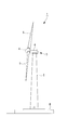
- FIG. 1 is a side view showing a wind turbine for wind power generation provided with a wind turbine rotor blade according to the present embodiment
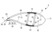
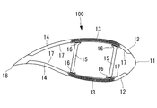
- FIG. 2 is a cross-sectional view of the wind turbine rotor blade according to the present embodiment
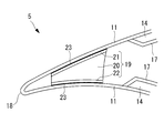
- FIG. 3 is an enlarged cross-sectional view of the main part of FIG. FIG.
- a wind turbine 1 for wind power generation includes a column (also referred to as “tower”) 2 standing on a foundation B, a nacelle 3 installed at the upper end of the column 2, and a substantially horizontal axis. And a rotor head 4 provided on the nacelle 3 so as to be rotatable around.
- a plurality of (for example, three) wind turbine rotor blades 5 are attached to the rotor head 4 in a radial pattern around the rotation axis. As a result, the force of the wind striking the wind turbine rotor blade 5 from the direction of the rotation axis of the rotor head 4 is converted into power for rotating the rotor head 4 around the rotation axis.
- the support column 2 is configured by connecting a plurality of (for example, three) units (not shown) vertically.
- the nacelle 3 is installed on a unit provided at the uppermost part of the units constituting the column 2, and a nacelle base plate (not shown) attached to the upper end of the column 2 and the nacelle base plate And a cover 6 covering from above.
- the wind turbine rotor 5 has a spar cap structure that satisfies both requirements of lightness and strength, and includes a skin material 11, a leading edge sandwich material 12, a spar cap material (main strength material). ) 13, a trailing edge sandwich material 14, and a sheer web (girder) 15.
- the leading edge sandwich material 12 and the trailing edge sandwich material 14 have a sandwich structure in which the outer skin material 11 and the inner skin material 17 are skin materials, and a resin foam such as PVC or wood such as balsa is a core material. .
- the outer skin material 11, the spar cap material 13, and the endothelial material 17 are each formed (configured) of fiber reinforced plastic (FRP).
- the spar cap material 13 is a member in which fiber reinforced plastics are laminated in multiple layers, and is in contact with the back surface (upper side in FIG. 2) and the abdominal side (lower side in FIG. 2) of the shear web 15 One is provided on each of the back side and the ventral side of the rotary blade 5. Further, the spar cap material 13 and the shear web 15 are connected (coupled) via an adhesive 16 that cures at room temperature.
- the bending strength in the flap direction of the wind turbine rotor blade 5 is mainly maintained by the spar cap material 13 formed of fiber reinforced plastic, and the leading edge sandwich material 12 and the trailing edge sandwich material 14 are: It is used as an auxiliary to maintain the buckling strength of the wind turbine rotor 5.
- the dorsal outer skin material 11 located on the rear edge 18 side of the rear edge end of the rear edge sandwich material 14 or the vicinity of the rear edge of the rear edge sandwich material A reinforcing material 19 is provided (disposed) between the outer skin material 11 on the ventral side or the vicinity of the rear edge of the trailing edge sandwich material.
- the reinforcing member 19 is disposed on the lighter core material 20, the skin material 21 disposed on the back side of the lighter core material 20 (back side), and the ventral side of the lighter core material 20. (Stomach side) skin material 22 is provided.
- the lightweight core material 20 is formed (configured) of a resin foam such as PVC or wood such as balsa, and is sandwiched between the skin material 21 and the skin material 22.
- Each of the skin materials 21 and 22 has the same length as the cord direction (the left-right direction in FIGS. 2 and 3) of the end face corresponding to (facing) the lightweight core material 20.
- Each of the skin materials 21 and 22 is formed of a fiber reinforced plastic in which reinforcing fibers (not shown) are oriented in the longitudinal direction of the wind turbine rotor 5 (direction perpendicular to the paper surface in FIGS. 2 and 3). )
- the skin material 21 is in contact with the end surface on the back side of the lightweight core material 20
- the skin material 22 is in contact with the end surface on the ventral side of the lightweight core material 20
- the lightweight core material 20 and the skin materials 21, 22 are integrally formed. Formed (configured).
- the skin material 11 and the skin material 21, and the skin material 11 and the skin material 22 are connected (coupled) via an adhesive 23 that cures at room temperature.
- the dorsal skin material 11 located on the rear edge 18 side of the rear edge end of the rear edge sandwich material 14 or the vicinity of the rear edge of the rear edge sandwich material is connected via the reinforcing material 19. Therefore, the bending stiffness in the edge direction at the trailing edge can be improved, the buckling strength against the load in the edge direction at the trailing edge can be improved, and the safety factor of the buckling strength can be increased by the safety factor of the material strength. The weight can be further reduced.
- the width of the trailing edge sandwich material 14 (length in the cord direction (left and right direction in FIG. 10)) becomes wide, it is possible to prevent the buckling strength of the trailing edge sandwich material 14 from being lowered with respect to the load in the edge direction. Therefore, the distance between the shear webs 15 in the cord direction, that is, the distance between the shear web 15 located on the front edge side and the shear web 15 located on the rear edge side can be narrowed, and the width of the spar cap material 13 is narrowed ( At this time, it is possible to increase the thickness of the spar cap material 13 while maintaining the same cross-sectional area of the spar cap material 13), and to improve the buckling strength of the spar cap material 13 against the load in the flap direction.
- the reinforcing fibers constituting the skin materials 21 and 22 are oriented along the longitudinal direction of the blade, so that the bending rigidity in the edge direction at the trailing edge portion is further increased.
- the buckling strength against the load in the edge direction at the trailing edge can be further improved, the safety factor of buckling strength can be made closer to the safety factor of material strength, and further weight reduction can be achieved. Can be planned.
- the rotor head 4 and the rotor head 4 are connected to a rotary bearing (not shown) that connects the root portion of the wind turbine rotor blade. It is possible to reduce the weight of a connecting shaft (not shown) that is installed and applies rotational motion to the wind turbine blades, and the load applied to the tower 2 that supports the wind turbine rotor blades 5 and the rotor head 4 can be reduced.
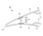
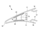
- FIG. 4 is an enlarged cross-sectional view of the main part of the wind turbine rotor blade according to the present embodiment, which is the same as FIG.
- the wind turbine rotor 30 according to the present embodiment is different from that of the first embodiment described above in that a reinforcing material 31 is provided instead of the reinforcing material 19. Since other components are the same as those of the first embodiment described above, description of these components is omitted here. In addition, the same code
- the reinforcing member 31 includes a trailing edge beam member 32, a skin material 21 disposed on the back side of the trailing edge beam member 32 (back side), and a trailing edge beam member 32. (Stomach side) skin material 22 is provided.
- the trailing edge girder 32 is a member having an I-shaped cross-sectional view, and is formed (configured) together with a fiber reinforced plastic (FRP) alone, a resin foam such as PVC, or wood such as balsa. And is sandwiched between the skin material 21 and the skin material 22.
- FRP fiber reinforced plastic
- PVC resin foam
- balsa wood
- Each of the skin materials 21 and 22 is formed so as to be longer than the length in the cord direction (left and right direction in FIG. 4) of the corresponding (opposing) end surface of the trailing edge beam member 32 (the flange length of the I shape in cross section). (It is configured.
- the skin material 21 is in contact with the end face on the back side of the trailing edge girder material 32, the skin material 22 is in contact with the end surface on the ventral side of the trailing edge girder material 32, and the rear edge girder material 32 and the skin materials 21, 22 are Are integrally formed (configured).
- FIG. 5 is an enlarged cross-sectional view of the main part of the wind turbine rotor blade according to the present embodiment, which is the same as FIG.
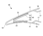
- the wind turbine rotor blade 40 according to this embodiment is different from that of the first embodiment described above in that a reinforcing material 41 is provided instead of the reinforcing material 19. Since other components are the same as those of the first embodiment described above, description of these components is omitted here. In addition, the same code
- the reinforcing member 41 includes a U-shaped girder 42, a skin material 21 disposed on the back side of the U-shaped girder 42 (back side),
- the U-shaped girder 42 is provided on the ventral side (abdominal side) of the skin material 22.
- the U-shaped girder 42 may be formed (configured) only with a fiber reinforced plastic (FRP) or with a foamed resin such as PVC or wood such as balsa. This is a member exhibiting a letter shape, and is sandwiched between the skin material 21 and the skin material 22.
- FRP fiber reinforced plastic
- PVC polyvinyl styrene
- balsa wood
- Each of the skin materials 21 and 22 has the same length as the length in the cord direction (left and right direction in FIG. 5) of the corresponding (opposing) end face of the U-shaped girder material 42.
- the skin material 21 is in contact with the end face on the back side of the U-shaped girder material 42, and the skin material 22 is in contact with the end surface on the ventral side of the U-shaped girder material 42, and the U-shaped girder material 42 and
- the skin materials 21 and 22 are integrally formed (configured).
- FIG. 6 is an enlarged cross-sectional view of a main part of the wind turbine rotor blade according to the present embodiment, which is the same as FIG.
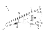
- the wind turbine rotor blade 50 according to the present embodiment is different from that of the first embodiment described above in that a reinforcing material 51 is provided instead of the reinforcing material 19. Since other components are the same as those of the first embodiment described above, description of these components is omitted here. In addition, the same code
- the reinforcing member 51 includes a trapezoidal beam 52, a skin material 21 disposed on the back side of the trapezoidal beam 52 (back side), and a trapezoidal beam 52. (Stomach side) skin material 22 is provided.
- the trapezoidal girder 52 may be formed (configured) only with fiber reinforced plastic (FRP), or with resin foam such as PVC, or wood such as balsa. It is sandwiched between the material 22.
- FRP fiber reinforced plastic
- resin foam such as PVC
- wood such as balsa
- Each of the skin materials 21 and 22 is formed (configured) so as to be longer than the length in the cord direction (the left-right direction in FIG. 6) of the corresponding (opposing) end face of the trapezoidal beam 52.
- the skin material 21 is in contact with the end face on the back side of the trapezoidal-shaped beam member 52
- the skin material 22 is in contact with the end surface on the ventral side of the trapezoid-shaped beam member 52
- the trapezoid-shaped beam member 52 and the skin materials 21, 22 are Are integrally formed (configured).
- FIG. 7 is an enlarged cross-sectional view of the main part of the wind turbine rotor blade according to the present embodiment, which is the same as FIG.
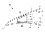
- the wind turbine rotor 60 according to the present embodiment is different from that of the first embodiment described above in that a reinforcing material 61 is provided instead of the reinforcing material 19. Since other components are the same as those of the first embodiment described above, description of these components is omitted here. In addition, the same code
- the reinforcing member 61 according to the present embodiment is such that the periphery (outside) of the reinforcing member 19 described in the first embodiment is covered with a (second) skin material 62. . That is, the reinforcing member 61 according to the present embodiment is disposed on the lightweight core member 20, the (first) skin member 21 disposed on the back side of the lightweight core member 20, and the ventral side of the lightweight core member 20. A (first) skin material 22 and a skin material 62 arranged so as to surround the outside of the lightweight core material 20 and the skin materials 21 and 22 are provided.
- the skin material 62 includes, for example, a + 45 ° fiber reinforced resin layer (not shown) in which reinforcing fibers are oriented with an inclination of + 45 ° with respect to the blade longitudinal direction of the wind turbine rotor blade 60 (the direction perpendicular to the paper surface in FIG. 7). ) And a ⁇ 45 ° fiber reinforced resin layer (not shown) oriented at an inclination of ⁇ 45 ° with respect to the blade longitudinal direction of the wind turbine rotor blade 60, is a double-biased fiber reinforced plastic.
- the skin material 62 is in contact with the end surface on the back side of the skin material 21, the end surface on the abdomen side of the skin material 22, the end surface on the front edge side of the lightweight core material 20, and the end surface on the rear edge side of the sandwich material 20.
- 20 and the skin materials 21, 22, 62 are integrally formed (configured).
- the skin material 11 and the skin material 60 are connected (coupled) via an adhesive 23 that cures at room temperature.
- the relative displacement in the blade longitudinal direction between the dorsal skin material 11 and the ventral skin material 11 is suppressed.
- Shear failure of the lightweight core material 20 due to relative displacement in the blade longitudinal direction with the outer skin material 11 can be prevented.
- Other functions and effects are the same as those of the above-described first embodiment, and thus description thereof is omitted here.
- FIG. 8 is an enlarged cross-sectional view of a main part of the wind turbine rotor blade according to the present embodiment, which is the same as FIG.
- the wind turbine rotor blade 70 according to the present embodiment differs from that of the fourth embodiment described above in that a reinforcing material 71 is provided instead of the reinforcing material 51. Since other components are the same as those of the fourth embodiment described above, description of these components is omitted here. In addition, the same code
- the reinforcing material 71 according to this embodiment is such that the periphery (outside) of the reinforcing material 51 described in the fourth embodiment is covered with a (second) skin material 72.
- the reinforcing member 71 according to the present embodiment is provided on the belly side of the trapezoidal beam 52, the (first) skin material 21 disposed on the back side of the trapezoidal beam 52, and the trapezoidal beam 52.
- the (first) skin material 22 to be disposed, the trapezoidal-shaped girder member 52 having a trapezoidal shape in a cross-sectional view, and the skin material 21 and 22 are disposed so as to surround the outside of the skin material 21 and 22.
- a skin material 72 is disposed so as to surround the outside of the skin material 21 and 22.
- the skin material 72 includes, for example, a + 45 ° fiber reinforced resin layer (not shown) in which reinforcing fibers are oriented with an inclination of + 45 ° with respect to the blade longitudinal direction of the wind turbine rotor blade 70 (direction perpendicular to the paper surface in FIG. 8). ) And a ⁇ 45 ° fiber reinforced resin layer (not shown) oriented at an inclination of ⁇ 45 ° with respect to the longitudinal direction of the wind turbine rotor blade 70, is a double-biased fiber reinforced plastic.
- the skin material 72 is partially joined to the abdomen side end surface of the skin material 21 and the back side end surface of the skin material 22, respectively, and the entire end surface on the front edge side of the trapezoidal shaped girder 52 and the trapezoidal shaped girder 52.
- the trapezoidal girder member 52 and the skin members 21, 22, 72 are integrally formed (configured).
- the skin material 11 and the skin material 21, and the skin material 11 and the skin material 22 are connected (coupled) via an adhesive 23 that cures at room temperature.
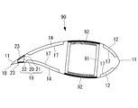
- all of the reinforcing members 19, 31, 41, 51, 61, and 71 are not applicable only to the wind turbine rotor blade having the structure shown in FIG. 2 or FIG. 10, but have, for example, the structure shown in FIG.
- the present invention can also be applied to the windmill rotor blade 90, that is, the windmill rotor blade 90 provided with the shear web 91 having a box structure.
- the end surface on the back side of the shear web 91 and the inner surface of the outer skin material 11, and the end surface on the stomach side of the shear web 91 and the inner surface of the outer skin material 11 are connected (coupled) via an adhesive 92 that cures at room temperature.
- any of the reinforcing members 19, 31, 41, 51, 61, and 71 is not applicable only to the wind turbine rotor blade having the structure shown in FIG. 2 or FIG. 10, for example, has the structure shown in FIG.
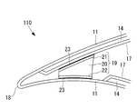
- the trailing edge of the wind turbine rotor 110 that is, the trailing edge sandwich material 14 disposed on the back side, is closer to the trailing edge than the trailing edge edge of the trailing edge sandwich material 14 disposed on the ventral side, or in the vicinity of the trailing edge 18.
- the present invention can also be applied to the wind turbine rotor blade 110 that extends to the end.
- the reinforcing members 19, 31, 41, 51, 61, 71 are composed of the endothelial material 17 located at the rear edge of the back-side rear edge sandwich material 14 and the ventral-side outer skin material 11 or the rear edge sandwich material 14. It is provided between the vicinity of the trailing edge of the rear edge.
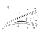
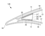
- none of the reinforcing members 19, 31, 41, 51, 61, and 71 can be applied only to the wind turbine rotor blade having the structure shown in FIG. 2 or FIG. 10, for example, has the structure shown in FIG.
- the trailing edge of the wind turbine rotor 120 that is, the trailing edge sandwich material 14 disposed on the ventral side is closer to the trailing edge than the trailing edge edge of the trailing edge sandwich material 14 disposed on the back side, or in the vicinity of the trailing edge 18.
- the present invention can also be applied to the wind turbine rotor blade 120 extending to the end.
- the reinforcing members 19, 31, 41, 51, 61, 71 are composed of the endothelial material 17 located at the rear edge of the ventral rear edge sandwich material 14 and the dorsal outer skin material 11 or the rear edge sandwich material 14. It is provided between the vicinity of the trailing edge of the rear edge.
- none of the reinforcing members 19, 31, 41, 51, 61, and 71 can be applied only to the wind turbine rotor blade having the structure shown in FIG. 2 or FIG. 10, for example, the structure shown in FIG.
- the trailing edge of the wind turbine rotor 130 that is, the trailing edge sandwich material 14 disposed on the back side and the abdomen side is behind the trailing edge sandwich material 14 described in the first to sixth embodiments.
- the present invention can also be applied to the wind turbine rotor 130 that extends to the rear edge side from the edge or to the vicinity of the rear edge 18.
- the reinforcing members 19, 31, 41, 51, 61, 71 are composed of the endothelial material 17 located at the rear edge of the dorsal rear edge sandwich material 14 and the rear edge of the ventral rear edge sandwich material 14. It will be provided between the endothelium material 17 located in the area. 9, FIG. 11, FIG. 12, and FIG. 13 show the reinforcing material 19 described in the first embodiment as a specific example of the reinforcing material. 51, 61 and 71 are not excluded.
Abstract
Description
前縁サンドイッチ材12と後縁サンドイッチ材14は、外皮材11と内皮材17をスキン材とし、PVC等の樹脂の発泡体や、バルサ等の木材をコア材とするサンドイッチ構造を有している。
なお、図10中の符号16は、スパーキャップ材13とシアウェブ15とを接続(連結)する接着剤である。 In addition, as shown in FIG. 10, in recent years, a wind
The leading
In addition, the code |
しかしその反面、後縁サンドイッチ材14の幅(コード方向(図10において左右方向)の長さ)が広くなり、エッジ方向の荷重に対する後縁サンドイッチ材14の座屈強度がますます低下してしまうといった問題点があった。 Here, in order to increase the buckling strength of the
However, on the other hand, the width of the trailing edge sandwich material 14 (length in the cord direction (left and right direction in FIG. 10)) is widened, and the buckling strength of the trailing
本発明に係る風車回転翼は、繊維強化プラスチックで形成された外皮材と、シアウェブと、このシアウェブよりも後縁側に配置された後縁サンドイッチ材とを有する風車回転翼であって、前記後縁サンドイッチ材の後縁端よりも後縁側に位置する背側の外皮材または前記後縁サンドイッチ材の後縁端近傍と、前記後縁サンドイッチ材の後縁端よりも後縁側に位置する腹側の外皮材または前記後縁サンドイッチ材の後縁端近傍とが、補強材を介して連結されている。 The present invention employs the following means in order to solve the above problems.
A windmill rotor blade according to the present invention is a windmill rotor blade having an outer skin material formed of a fiber reinforced plastic, a shear web, and a trailing edge sandwich material arranged on the trailing edge side of the shear web, and the trailing edge A dorsal skin material located on the rear edge side of the rear edge edge of the sandwich material or a vicinity of the rear edge edge of the rear edge sandwich material, and an abdominal side located on the rear edge side of the rear edge edge of the rear edge sandwich material. The outer skin material or the vicinity of the rear edge of the trailing edge sandwich material is connected via a reinforcing material.
2 支柱(タワー)
3 ナセル
4 ローターヘッド
5 風車回転翼
6 ナセルカバー
11 外皮材
12 前縁サンドイッチ材
13 スパーキャップ材(主強度材)
14 後縁サンドイッチ材
15 シアウェブ
16 接着剤
17 内皮材
18 後縁
19 補強材
20 軽量コア材
21 スキン材(背側スキン材)
22 スキン材(腹側スキン材)
23 接着剤
30 風車回転翼
31 補強材
32 後縁桁材
40 風車回転翼
41 補強材
42 コの字形状桁材
50 風車回転翼
51 補強材
52 台形形状桁材
60 風車回転翼
61 補強材
62 (第2の)スキン材
70 風車回転翼
71 補強材
72 (第2の)スキン材
90 風車回転翼
91 シアウェブ(桁材)
92 接着剤
B 基礎 1 Windmill for
3
14 Rear
22 Skin material (ventral skin material)
23 Adhesive 30
92 Adhesive B Basic
図1は本実施形態に係る風車回転翼を具備した風力発電用風車を示す側面図、図2は本実施形態に係る風車回転翼の断面図、図3は図2の要部を拡大した断面図である。 Hereinafter, a first embodiment of a wind turbine rotor blade according to the present invention will be described with reference to FIGS. 1 to 3.
FIG. 1 is a side view showing a wind turbine for wind power generation provided with a wind turbine rotor blade according to the present embodiment, FIG. 2 is a cross-sectional view of the wind turbine rotor blade according to the present embodiment, and FIG. 3 is an enlarged cross-sectional view of the main part of FIG. FIG.
ローターヘッド4には、その回転軸線周りに放射状にして複数枚(例えば、3枚)の風車回転翼5が取り付けられている。これにより、ローターヘッド4の回転軸線方向から風車回転翼5に当たった風の力が、ローターヘッド4を回転軸線周りに回転させる動力に変換されるようになっている。 As shown in FIG. 1, a
A plurality of (for example, three) wind
また、ナセル3は、支柱2を構成するユニットのうち、最上部に設けられるユニット上に設置されており、支柱2の上端に取り付けられるナセル台板(図示せず)と、このナセル台板を上方から覆うカバー6とを有している。 The
The
前縁サンドイッチ材12と後縁サンドイッチ材14は、外皮材11と内皮材17をスキン材とし、PVC等の樹脂の発泡体や、バルサ等の木材をコア材とするサンドイッチ構造を有している。 As shown in FIG. 2, the
The leading
図2または図3に示すように、補強材19は、軽量コア材20と、軽量コア材20の背側に配置される(背側)スキン材21と、軽量コア材20の腹側に配置される(腹側)スキン材22とを備えている。 Now, in the
As shown in FIG. 2 or 3, the reinforcing
スキン材21,22はそれぞれ、軽量コア材20の対応(対向)する端面のコード方向(図2および図3において左右方向)の長さと同じ長さを有している。また、スキン材21,22はそれぞれ、風車回転翼5の翼長手方向(図2および図3において紙面に垂直な方向)に強化繊維(図示せず)が配向された繊維強化プラスチックで形成(構成)されている。 The
Each of the
そして、その結果、後縁サンドイッチ材14の幅(コード方向(図10において左右方向)の長さ)が広くなっても、エッジ方向の荷重に対する後縁サンドイッチ材14の座屈強度の低下を防げるので、シアウェブ15のコード方向の間隔、すなわち、前縁側に位置するシアウェブ15と、後縁側に位置するシアウェブ15との間の距離を狭くすることができ、スパーキャップ材13の幅を狭くする(このとき、スパーキャップ材13の断面積は同等に維持しながら、スパーキャップ材13を厚くする)ことができて、フラップ方向の荷重に対するスパーキャップ材13の座屈強度を向上させることができる。 According to the
As a result, even if the width of the trailing edge sandwich material 14 (length in the cord direction (left and right direction in FIG. 10)) becomes wide, it is possible to prevent the buckling strength of the trailing
図4は本実施形態に係る風車回転翼の要部を拡大した断面図であって、図3と同様の図である。 A second embodiment of the wind turbine rotor blade according to the present invention will be described with reference to FIG.
FIG. 4 is an enlarged cross-sectional view of the main part of the wind turbine rotor blade according to the present embodiment, which is the same as FIG.
なお、上述した実施形態と同一の部材には同一の符号を付している。 The
In addition, the same code | symbol is attached | subjected to the member same as embodiment mentioned above.
スキン材21,22はそれぞれ、後縁桁材32の対応(対向)する端面のコード方向(図4において左右方向)の長さ(断面視I形状のフランジ長さ)よりも長くなるように形成(構成)されている。
スキン材21は、後縁桁材32の背側の端面に接し、スキン材22は、後縁桁材32の腹側の端面に接しており、後縁桁材32およびスキン材21,22は、一体に形成(構成)されている。 The trailing
Each of the
The
図5は本実施形態に係る風車回転翼の要部を拡大した断面図であって、図3と同様の図である。 A third embodiment of the wind turbine rotor blade according to the present invention will be described with reference to FIG.
FIG. 5 is an enlarged cross-sectional view of the main part of the wind turbine rotor blade according to the present embodiment, which is the same as FIG.
なお、上述した実施形態と同一の部材には同一の符号を付している。 The wind
In addition, the same code | symbol is attached | subjected to the member same as embodiment mentioned above.
スキン材21,22はそれぞれ、コの字形状桁材42の対応(対向)する端面のコード方向(図5において左右方向)の長さと同じ長さを有している。
スキン材21は、コの字形状桁材42の背側の端面に接し、スキン材22は、コの字形状桁材42の腹側の端面に接しており、コの字形状桁材42およびスキン材21,22は、一体に形成(構成)されている。 The U-shaped girder 42 may be formed (configured) only with a fiber reinforced plastic (FRP) or with a foamed resin such as PVC or wood such as balsa. This is a member exhibiting a letter shape, and is sandwiched between the
Each of the
The
図6は本実施形態に係る風車回転翼の要部を拡大した断面図であって、図3と同様の図である。 A fourth embodiment of the wind turbine rotor blade according to the present invention will be described with reference to FIG.
FIG. 6 is an enlarged cross-sectional view of a main part of the wind turbine rotor blade according to the present embodiment, which is the same as FIG.
なお、上述した実施形態と同一の部材には同一の符号を付している。 The wind
In addition, the same code | symbol is attached | subjected to the member same as embodiment mentioned above.
スキン材21,22はそれぞれ、台形形状桁材52の対応(対向)する端面のコード方向(図6において左右方向)の長さよりも長くなるように形成(構成)されている。
スキン材21は、台形形状桁材52の背側の端面に接し、スキン材22は、台形形状桁材52の腹側の端面に接しており、台形形状桁材52およびスキン材21,22は、一体に形成(構成)されている。 The
Each of the
The
図7は本実施形態に係る風車回転翼の要部を拡大した断面図であって、図3と同様の図である。 A fifth embodiment of the wind turbine rotor blade according to the present invention will be described with reference to FIG.
FIG. 7 is an enlarged cross-sectional view of the main part of the wind turbine rotor blade according to the present embodiment, which is the same as FIG.
なお、上述した実施形態と同一の部材には同一の符号を付している。 The
In addition, the same code | symbol is attached | subjected to the member same as embodiment mentioned above.
スキン材62は、スキン材21の背側の端面、スキン材22の腹側の端面、軽量コア材20の前縁側の端面、およびサンドイッチ材20の後縁側の端面に接しており、軽量コア材20およびスキン材21,22,62は、一体に形成(構成)されている。また、外皮材11とスキン材60とは、常温で硬化する接着剤23を介して接続(連結)されている。 The
The
その他の作用効果は、上述した第1実施形態のものと同じであるので、ここではその説明を省略する。 According to the wind
Other functions and effects are the same as those of the above-described first embodiment, and thus description thereof is omitted here.
図8は本実施形態に係る風車回転翼の要部を拡大した断面図であって、図6と同様の図である。 A sixth embodiment of the wind turbine rotor blade according to the present invention will be described with reference to FIG.
FIG. 8 is an enlarged cross-sectional view of a main part of the wind turbine rotor blade according to the present embodiment, which is the same as FIG.
なお、上述した実施形態と同一の部材には同一の符号を付している。 The wind
In addition, the same code | symbol is attached | subjected to the member same as embodiment mentioned above.
スキン材72は、スキン材21の腹側の端面およびスキン材22の背側の端面とそれぞれ部分的に接合されているとともに、台形形状桁材52の前縁側の端面全体および台形形状桁材52の後縁側の端面全体とそれぞれ接合されており、台形形状桁材52およびスキン材21,22,72は、一体に形成(構成)されている。また、外皮材11とスキン材21、外皮材11とスキン材22とはそれぞれ、常温で硬化する接着剤23を介して接続(連結)されている。 The
The
なお、図9、図11、図12、図13には、補強材の一具体例として第1実施形態のところで説明した補強材19を示しているが、これはその他の補強材31,41,51,61,71を排除するものではない。 Furthermore, none of the reinforcing
9, FIG. 11, FIG. 12, and FIG. 13 show the reinforcing
Claims (4)
- 繊維強化プラスチックで形成された外皮材と、シアウェブと、このシアウェブよりも後縁側に配置された後縁サンドイッチ材とを有する風車回転翼であって、
前記後縁サンドイッチ材の後縁端よりも後縁側に位置する背側の外皮材または前記後縁サンドイッチ材の後縁端近傍と、前記後縁サンドイッチ材の後縁端よりも後縁側に位置する腹側の外皮材または前記後縁サンドイッチ材の後縁端近傍とが、補強材を介して連結されていることを特徴とする風車回転翼。 A windmill rotor blade having a skin material formed of fiber-reinforced plastic, a shear web, and a trailing edge sandwich material disposed on the trailing edge side of the shear web,
It is located on the back side of the rear edge of the trailing edge sandwich material or in the vicinity of the trailing edge of the trailing edge sandwich material, or on the rear edge side of the trailing edge sandwich material. A windmill rotor blade characterized by being connected to a ventral skin material or the vicinity of a trailing edge of the trailing edge sandwich material via a reinforcing material. - 前記補強材が、軽量コア材と、この軽量コア材の背側に配置される背側スキン材と、前記軽量コア材の腹側に配置される腹側スキン材とを備え、
前記軽量コア材、前記背側スキン材、および前記腹側スキン材が一体に形成されているとともに、
前記背側スキン材および/または前記腹側スキン材は、翼長手方向に強化繊維が配向された繊維強化プラスチックで形成されていることを特徴とする請求項1に記載の風車回転翼。 The reinforcing material comprises a lightweight core material, a back skin material disposed on the back side of the lightweight core material, and a ventral skin material disposed on the ventral side of the lightweight core material,
The lightweight core material, the back skin material, and the ventral skin material are integrally formed,
The windmill rotor blade according to claim 1, wherein the back skin material and / or the ventral skin material is formed of fiber reinforced plastic in which reinforcing fibers are oriented in a longitudinal direction of the blade. - 前記軽量コア材、前記背側スキン材、および前記腹側スキン材の外側に配置された第2のスキン材を備え、
前記軽量コア材、前記背側スキン材、前記腹側スキン材、および前記第2のスキン材が一体に形成されていることを特徴とする請求項2に記載の風車回転翼。 A second skin material disposed outside the lightweight core material, the back skin material, and the ventral skin material;
The wind turbine rotor blade according to claim 2, wherein the lightweight core material, the back skin material, the ventral skin material, and the second skin material are integrally formed. - 請求項1から3のいずれか一項に記載の風車回転翼を備えてなることを特徴とする風力発電用風車。 A wind turbine for wind power generation comprising the wind turbine rotor blade according to any one of claims 1 to 3.
Priority Applications (8)
| Application Number | Priority Date | Filing Date | Title |
|---|---|---|---|
| PCT/JP2009/071574 WO2011077545A1 (en) | 2009-12-25 | 2009-12-25 | Windmill rotary vane |
| AU2009357031A AU2009357031A1 (en) | 2009-12-25 | 2009-12-25 | Wind-turbine rotor blade |
| US13/389,534 US8556590B2 (en) | 2009-12-25 | 2009-12-25 | Wind-turbine rotor blade |
| JP2011547158A JP5536103B2 (en) | 2009-12-25 | 2009-12-25 | Wind turbine rotor |
| CN200980161076XA CN102575649A (en) | 2009-12-25 | 2009-12-25 | Windmill rotary vane |
| IN1230DEN2012 IN2012DN01230A (en) | 2009-12-25 | 2009-12-25 | |
| MX2012001612A MX2012001612A (en) | 2009-12-25 | 2009-12-25 | Windmill rotary vane. |
| EP09852562.9A EP2518311A4 (en) | 2009-12-25 | 2009-12-25 | Windmill rotary vane |
Applications Claiming Priority (1)
| Application Number | Priority Date | Filing Date | Title |
|---|---|---|---|
| PCT/JP2009/071574 WO2011077545A1 (en) | 2009-12-25 | 2009-12-25 | Windmill rotary vane |
Publications (1)
| Publication Number | Publication Date |
|---|---|
| WO2011077545A1 true WO2011077545A1 (en) | 2011-06-30 |
Family
ID=44195107
Family Applications (1)
| Application Number | Title | Priority Date | Filing Date |
|---|---|---|---|
| PCT/JP2009/071574 WO2011077545A1 (en) | 2009-12-25 | 2009-12-25 | Windmill rotary vane |
Country Status (8)
| Country | Link |
|---|---|
| US (1) | US8556590B2 (en) |
| EP (1) | EP2518311A4 (en) |
| JP (1) | JP5536103B2 (en) |
| CN (1) | CN102575649A (en) |
| AU (1) | AU2009357031A1 (en) |
| IN (1) | IN2012DN01230A (en) |
| MX (1) | MX2012001612A (en) |
| WO (1) | WO2011077545A1 (en) |
Cited By (9)
| Publication number | Priority date | Publication date | Assignee | Title |
|---|---|---|---|---|
| WO2013086667A1 (en) * | 2011-12-12 | 2013-06-20 | General Electric Company | Wind turbine blade shear web connection assembly |
| CN103174600A (en) * | 2011-12-22 | 2013-06-26 | 华锐风电科技(集团)股份有限公司 | Fan blade |
| KR20160080587A (en) * | 2014-12-30 | 2016-07-08 | 한국에너지기술연구원 | Composite blade having Local reinforcement structure |
| JP6002865B1 (en) * | 2015-09-03 | 2016-10-05 | 積水化成品工業株式会社 | Windmill blade |
| CN109895411A (en) * | 2017-12-08 | 2019-06-18 | 苏州天顺风电叶片技术有限公司 | A kind of web integral type adhesive tool |
| KR20190122834A (en) * | 2017-03-13 | 2019-10-30 | 아르끄마 프랑스 | Wind turbine blades made of thermoplastic polymer composite, parts and method for manufacturing the blades |
| CN110905719A (en) * | 2019-12-02 | 2020-03-24 | 三一重能有限公司 | Wind power blade and wind power generation equipment |
| CN112065656A (en) * | 2020-08-24 | 2020-12-11 | 河南恒聚新能源设备有限公司 | Guide vane and vertical axis turbine wind power generation device |
| CN112065658A (en) * | 2020-08-24 | 2020-12-11 | 河南恒聚新能源设备有限公司 | Moving blade and vertical axis turbine wind power generation device |
Families Citing this family (14)
| Publication number | Priority date | Publication date | Assignee | Title |
|---|---|---|---|---|
| DE102009033164A1 (en) * | 2009-07-13 | 2011-01-27 | Repower Systems Ag | Rotor blade of a wind energy plant and method for manufacturing a rotor blade of a wind turbine |
| JP5427597B2 (en) * | 2009-12-25 | 2014-02-26 | 三菱重工業株式会社 | Wind turbine rotor |
| CN102575649A (en) * | 2009-12-25 | 2012-07-11 | 三菱重工业株式会社 | Windmill rotary vane |
| GB201109412D0 (en) * | 2011-06-03 | 2011-07-20 | Blade Dynamics Ltd | A wind turbine rotor |
| GB201217212D0 (en) | 2012-09-26 | 2012-11-07 | Blade Dynamics Ltd | Windturbine blade |
| DE102012217904A1 (en) * | 2012-10-01 | 2014-04-03 | Repower Systems Se | Fiber composite component and rotor blade |
| CN102927051A (en) * | 2012-11-15 | 2013-02-13 | 江苏中联风能机械有限公司 | Improved blade of large-sized air cooling axial flow fan |
| DK3027893T3 (en) * | 2013-07-30 | 2018-01-08 | Lm Wp Patent Holding As | A wind turbine wing with a fortress line next to a sandwich panel in the wing |
| EP2927481B1 (en) * | 2014-03-31 | 2021-09-22 | Siemens Gamesa Renewable Energy A/S | Rotor blade for a wind turbine |
| US10066600B2 (en) | 2014-05-01 | 2018-09-04 | Tpi Composites, Inc. | Wind turbine rotor blade and method of construction |
| CN105402084B (en) * | 2015-12-29 | 2017-11-10 | 南京高传机电自动控制设备有限公司 | A kind of novel wind motor combined blade |
| DE102016007675A1 (en) * | 2016-06-24 | 2017-12-28 | Senvion Gmbh | Trailing edge belt with rectangular cross section |
| US11131290B2 (en) * | 2019-06-25 | 2021-09-28 | General Electric Company | Scarf connection for a wind turbine rotor blade |
| CN113757036B (en) * | 2021-08-31 | 2023-02-28 | 株洲时代新材料科技股份有限公司 | Wind power blade with improved trailing edge structure and manufacturing method thereof |
Citations (5)
| Publication number | Priority date | Publication date | Assignee | Title |
|---|---|---|---|---|
| JPS57210171A (en) * | 1981-04-01 | 1982-12-23 | Messerschmitt Boelkow Blohm | Aerodynamical large-sized blade, particularly, rotor blade for large-sized air force device |
| US4976587A (en) * | 1988-07-20 | 1990-12-11 | Dwr Wind Technologies Inc. | Composite wind turbine rotor blade and method for making same |
| JP2002137307A (en) * | 2000-11-02 | 2002-05-14 | Toray Ind Inc | Blade structure of windmill made of fiber-reinforced resin |
| JP2002357176A (en) * | 2001-03-27 | 2002-12-13 | Mitsubishi Heavy Ind Ltd | Composite material blade for wind power generating device |
| WO2008086805A2 (en) | 2007-01-16 | 2008-07-24 | Danmarks Tekniske Universitet | Reinforced blade for wind turbine |
Family Cites Families (15)
| Publication number | Priority date | Publication date | Assignee | Title |
|---|---|---|---|---|
| US5375324A (en) * | 1993-07-12 | 1994-12-27 | Flowind Corporation | Vertical axis wind turbine with pultruded blades |
| US7802968B2 (en) * | 2005-07-29 | 2010-09-28 | General Electric Company | Methods and apparatus for reducing load in a rotor blade |
| US7438533B2 (en) * | 2005-12-15 | 2008-10-21 | General Electric Company | Wind turbine rotor blade |
| JP4699255B2 (en) * | 2006-03-24 | 2011-06-08 | 三菱重工業株式会社 | Windmill wing |
| US20090140527A1 (en) * | 2007-11-30 | 2009-06-04 | General Electric Company | Wind turbine blade stiffeners |
| US8622709B2 (en) * | 2008-06-05 | 2014-01-07 | Mitsubishi Heavy Industries, Ltd. | Wind turbine blade and wind power generator using the same |
| EP2304228B1 (en) * | 2008-06-24 | 2012-02-22 | Danmarks Tekniske Universitet | A reinforced wind turbine blade |
| US8043065B2 (en) * | 2009-05-01 | 2011-10-25 | General Electric Company | Wind turbine blade with prefabricated leading edge segments |
| JP2011032987A (en) * | 2009-08-05 | 2011-02-17 | Nitto Denko Corp | Reinforcing sheet for wind turbine generator blade, reinforcing structure of wind turbine generator blade, wind turbine generator, and method of reinforcing wind turbine generator blade |
| JP2011032988A (en) * | 2009-08-05 | 2011-02-17 | Nitto Denko Corp | Foam filler for wind turbine generator blade, foam filling part for wind turbine generator blade, wind turbine generator blade, wind turbine generator, and method of manufacturing wind turbine generator blade |
| US8702397B2 (en) * | 2009-12-01 | 2014-04-22 | General Electric Company | Systems and methods of assembling a rotor blade for use in a wind turbine |
| JP5308323B2 (en) * | 2009-12-22 | 2013-10-09 | 三菱重工業株式会社 | Wind turbine blade and wind power generator using the same |
| JP5484892B2 (en) * | 2009-12-25 | 2014-05-07 | 三菱重工業株式会社 | Wind turbine rotor |
| JP5427597B2 (en) * | 2009-12-25 | 2014-02-26 | 三菱重工業株式会社 | Wind turbine rotor |
| CN102575649A (en) * | 2009-12-25 | 2012-07-11 | 三菱重工业株式会社 | Windmill rotary vane |
-
2009
- 2009-12-25 CN CN200980161076XA patent/CN102575649A/en active Pending
- 2009-12-25 AU AU2009357031A patent/AU2009357031A1/en not_active Abandoned
- 2009-12-25 JP JP2011547158A patent/JP5536103B2/en active Active
- 2009-12-25 WO PCT/JP2009/071574 patent/WO2011077545A1/en active Application Filing
- 2009-12-25 MX MX2012001612A patent/MX2012001612A/en not_active Application Discontinuation
- 2009-12-25 EP EP09852562.9A patent/EP2518311A4/en not_active Withdrawn
- 2009-12-25 US US13/389,534 patent/US8556590B2/en active Active
- 2009-12-25 IN IN1230DEN2012 patent/IN2012DN01230A/en unknown
Patent Citations (5)
| Publication number | Priority date | Publication date | Assignee | Title |
|---|---|---|---|---|
| JPS57210171A (en) * | 1981-04-01 | 1982-12-23 | Messerschmitt Boelkow Blohm | Aerodynamical large-sized blade, particularly, rotor blade for large-sized air force device |
| US4976587A (en) * | 1988-07-20 | 1990-12-11 | Dwr Wind Technologies Inc. | Composite wind turbine rotor blade and method for making same |
| JP2002137307A (en) * | 2000-11-02 | 2002-05-14 | Toray Ind Inc | Blade structure of windmill made of fiber-reinforced resin |
| JP2002357176A (en) * | 2001-03-27 | 2002-12-13 | Mitsubishi Heavy Ind Ltd | Composite material blade for wind power generating device |
| WO2008086805A2 (en) | 2007-01-16 | 2008-07-24 | Danmarks Tekniske Universitet | Reinforced blade for wind turbine |
Non-Patent Citations (1)
| Title |
|---|
| See also references of EP2518311A4 * |
Cited By (14)
| Publication number | Priority date | Publication date | Assignee | Title |
|---|---|---|---|---|
| WO2013086667A1 (en) * | 2011-12-12 | 2013-06-20 | General Electric Company | Wind turbine blade shear web connection assembly |
| CN103174600A (en) * | 2011-12-22 | 2013-06-26 | 华锐风电科技(集团)股份有限公司 | Fan blade |
| KR20160080587A (en) * | 2014-12-30 | 2016-07-08 | 한국에너지기술연구원 | Composite blade having Local reinforcement structure |
| KR101678015B1 (en) | 2014-12-30 | 2016-11-21 | 한국에너지기술연구원 | Composite blade having Local reinforcement structure |
| JP6002865B1 (en) * | 2015-09-03 | 2016-10-05 | 積水化成品工業株式会社 | Windmill blade |
| WO2017037930A1 (en) * | 2015-09-03 | 2017-03-09 | 積水化成品工業株式会社 | Windmill blade |
| JP2020510157A (en) * | 2017-03-13 | 2020-04-02 | アルケマ フランス | Wind turbine blades made of thermoplastic polymer composites, parts of the blades and methods of production |
| KR20190122834A (en) * | 2017-03-13 | 2019-10-30 | 아르끄마 프랑스 | Wind turbine blades made of thermoplastic polymer composite, parts and method for manufacturing the blades |
| JP7158401B2 (en) | 2017-03-13 | 2022-10-21 | アルケマ フランス | Wind turbine blades made of thermoplastic polymer composites, components of said blades and methods of production |
| KR102478910B1 (en) * | 2017-03-13 | 2022-12-16 | 아르끄마 프랑스 | Wind turbine blades made of thermoplastic polymer composites, parts of the blades and manufacturing methods |
| CN109895411A (en) * | 2017-12-08 | 2019-06-18 | 苏州天顺风电叶片技术有限公司 | A kind of web integral type adhesive tool |
| CN110905719A (en) * | 2019-12-02 | 2020-03-24 | 三一重能有限公司 | Wind power blade and wind power generation equipment |
| CN112065656A (en) * | 2020-08-24 | 2020-12-11 | 河南恒聚新能源设备有限公司 | Guide vane and vertical axis turbine wind power generation device |
| CN112065658A (en) * | 2020-08-24 | 2020-12-11 | 河南恒聚新能源设备有限公司 | Moving blade and vertical axis turbine wind power generation device |
Also Published As
| Publication number | Publication date |
|---|---|
| IN2012DN01230A (en) | 2015-04-10 |
| EP2518311A1 (en) | 2012-10-31 |
| AU2009357031A1 (en) | 2012-03-01 |
| MX2012001612A (en) | 2012-06-01 |
| JPWO2011077545A1 (en) | 2013-05-02 |
| US8556590B2 (en) | 2013-10-15 |
| US20120141282A1 (en) | 2012-06-07 |
| EP2518311A4 (en) | 2014-03-05 |
| CN102575649A (en) | 2012-07-11 |
| JP5536103B2 (en) | 2014-07-02 |
Similar Documents
| Publication | Publication Date | Title |
|---|---|---|
| JP5536103B2 (en) | Wind turbine rotor | |
| US11028824B2 (en) | Wind turbine blade with a trailing edge spacing section | |
| US8186964B2 (en) | Spar assembly for a wind turbine rotor blade | |
| JP5427597B2 (en) | Wind turbine rotor | |
| JP5484892B2 (en) | Wind turbine rotor | |
| DK2246558T3 (en) | Windmill blade with prefabricated leading edge segments | |
| WO2011078327A1 (en) | Rotary blade of windmill and method of manufacturing rotary blade of windmill | |
| DK3027893T3 (en) | A wind turbine wing with a fortress line next to a sandwich panel in the wing | |
| JP2011137386A5 (en) | ||
| JP2011137388A5 (en) | ||
| CN101446263A (en) | Wind turbine blade stiffeners | |
| KR20110100192A (en) | Wind turbine blade and wind turbine generator using the same | |
| EP2159414B1 (en) | Wind turbine blades with cross webs | |
| US20160290314A1 (en) | Wind turbine blade with wave shaped trailing edge | |
| BR112020003184B1 (en) | ROTOR BLADE ASSEMBLY AND CONNECTION STRUCTURE | |
| JP6475767B2 (en) | Wind turbine blade and method for reinforcing wind turbine blade | |
| JP2020084812A (en) | Windmill blade and wind power generation device | |
| JP2005147080A (en) | Blade of horizontal axis wind mill |
Legal Events
| Date | Code | Title | Description |
|---|---|---|---|
| WWE | Wipo information: entry into national phase |
Ref document number: 200980161076.X Country of ref document: CN |
|
| 121 | Ep: the epo has been informed by wipo that ep was designated in this application |
Ref document number: 09852562 Country of ref document: EP Kind code of ref document: A1 |
|
| WWE | Wipo information: entry into national phase |
Ref document number: 2011547158 Country of ref document: JP |
|
| WWE | Wipo information: entry into national phase |
Ref document number: MX/A/2012/001612 Country of ref document: MX |
|
| WWE | Wipo information: entry into national phase |
Ref document number: 13389534 Country of ref document: US Ref document number: 2009357031 Country of ref document: AU |
|
| WWE | Wipo information: entry into national phase |
Ref document number: 1230/DELNP/2012 Country of ref document: IN Ref document number: 2009852562 Country of ref document: EP |
|
| ENP | Entry into the national phase |
Ref document number: 2009357031 Country of ref document: AU Date of ref document: 20091225 Kind code of ref document: A |
|
| NENP | Non-entry into the national phase |
Ref country code: DE |