USRE34551E - Ducted fan - Google Patents
Ducted fan Download PDFInfo
- Publication number
- USRE34551E USRE34551E US07/886,230 US88623092A USRE34551E US RE34551 E USRE34551 E US RE34551E US 88623092 A US88623092 A US 88623092A US RE34551 E USRE34551 E US RE34551E
- Authority
- US
- United States
- Prior art keywords
- cowling
- grill
- ducted fan
- fan
- ribs
- Prior art date
- Legal status (The legal status is an assumption and is not a legal conclusion. Google has not performed a legal analysis and makes no representation as to the accuracy of the status listed.)
- Expired - Lifetime
Links
Images


Classifications
-
- F—MECHANICAL ENGINEERING; LIGHTING; HEATING; WEAPONS; BLASTING
- F04—POSITIVE - DISPLACEMENT MACHINES FOR LIQUIDS; PUMPS FOR LIQUIDS OR ELASTIC FLUIDS
- F04D—NON-POSITIVE-DISPLACEMENT PUMPS
- F04D29/00—Details, component parts, or accessories
- F04D29/70—Suction grids; Strainers; Dust separation; Cleaning
- F04D29/701—Suction grids; Strainers; Dust separation; Cleaning especially adapted for elastic fluid pumps
- F04D29/703—Suction grids; Strainers; Dust separation; Cleaning especially adapted for elastic fluid pumps specially for fans, e.g. fan guards
-
- F—MECHANICAL ENGINEERING; LIGHTING; HEATING; WEAPONS; BLASTING
- F04—POSITIVE - DISPLACEMENT MACHINES FOR LIQUIDS; PUMPS FOR LIQUIDS OR ELASTIC FLUIDS
- F04D—NON-POSITIVE-DISPLACEMENT PUMPS
- F04D25/00—Pumping installations or systems
- F04D25/02—Units comprising pumps and their driving means
- F04D25/08—Units comprising pumps and their driving means the working fluid being air, e.g. for ventilation
Definitions
- the present invention is an improved design of the ducted fan set forth in U.S. Pat. Nos. 2,554,602, 2,554,600 and 2,554,601.
- Another object of the present invention is to provide a new and improved ducted fan wherein the front grill and the inner cowling are integral and are easily removable by deflecting four separate tabs positioned around the periphery of the outer cowling.
- Another object of the invention is to provide a new and improved single leg support for the fan which allows the fan to pivotally turn on the support while a preloaded spring counteracts the offset weight of the fan and retains it in place.
- the support leg also is a conduit for the wires which supply the motor.
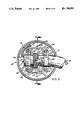
- FIG. 1 is a side elevational view of the fan in longitudinal section
- FIG. 2 is a front view of the fan normal to the grill
- FIG. 3 is a front perspective view of the fan
- FIG. 4 is a rear perspective view of the fan
- FIG. 5 is a partial plan view of the fan grill to an enlarged scale
- FIG. 6 is a sectional view to an enlarged scale taken along line 6--6 of FIG. 5;
- FIG. 7 is a partial sectional view to an enlarged scale of the inner and outer cowling
- FIG. 8 is a sectional view to an enlarged scale taken along line 8--8 of FIG. 9;
- FIG. 9 is a plan view of the fan base and its support leg with the cover plate removed.
- the drawings illustrate a ducted blade-type fan which is generally referred to by reference numeral 10.
- the fan 10 is mounted on a tubular support leg 12.
- the leg 12 includes a curved floor-engaging portion 14 and a short horizontal mounting portion 16 to which the fan base 32 is rotatably attached.
- Support leg 2 is fabricated from steel tubing and bent to its particular shape by commonly-known tube-bending techniques.
- Support leg 12 also functions as a conduit for the electrical wires 18 from motor 20 which enter leg 12 at its upper end, as seen in FIG. 9, and exit the leg 2 at its lower end 22.
- Fan motor 20 carries an impeller blade 24 on its drive shaft which includes three blades 26, 28 and 30. Fan motor 20 is concentrically bolted to base member 32 by four bolts 34.
- Base member 32 is a plastic injection molded part formed at the same time with duct 62 and outer cowling 68, later described in detail.
- Formed on base 32 are a series of motor-mounting pads 36. Attaching the support leg 12 to the fan base 32 are a pair of u-shaped straps 38 which urge leg portion 16 against an arcuate-shaped saddle 40 molded in base member 32, as best seen in FIG. 8.
- a coil spring 42 Positioned around leg portion 16, as seen in FIGS. 8 and 9, is a coil spring 42 having straight end sections 44 and 46. End section 44 is restrained from movement around the support leg by a small offset tab 48 which is spotwelded to tube 16. The amount of rotating friction between tube 16, saddle 40, and the straps 38 can be determined by tightening nuts 50 on bolts 34.
- Coil spring 42 when installed, has a preload force acting on motor 20, as best seen in FIG. 8, which urges the motor in a clockwise direction. This preload from spring 42 will offset the weight-created moment from the fan and its ducts attempting to rotate the fan 10 in a counterclockwise direction, as seen in FIG. 1. Also positioned on bolts 34 are a pair of rubber mounts 52 which have the ends of mounting straps 38 sandwiched therebetween.
- Base member 32 includes a peripheral ridge 54 which supports a cover plate 56.
- the cover plate has a matching retention groove 58 around its inside diameter which allows it to be snapped to the base member 32.
- Cover plate 56 has an circulate opening 60 therein, as seen in FIG. 8, permitting the support leg 12 to pass through.
- duct 62 Formed with base 32 is a funnel-shaped duct 62, as best seen in FIG. 1, which connects through a series of radially extending ribs 64, as seen in FIGS. 1 and 4.
- Duct 62 is tapered outward at its inlet end 66 to a diameter substantially increasing its cross sectional area.
- the outer cowling 68 is also formed with duct 62 and is connected to duct 62 by a second series of ribs 70, as seen in FIGS. 1 and 4, which have a similar lateral spacing, as previously-mentioned ribs 64.
- Base member 32, duct 62 and outer cowling 68 are all molded in a single piece through joining ribs 64 and 70.
- outer cowling 68 Removably positioned within outer cowling 68 is an inner cowling 72 which is also funnel-shaped from its larger intake end 74 to its smaller discharge end 76. Most of the axial length of cowling 68 is a constant diameter similar to discharge end 76.
- a circular grill 80 Attached to the discharge end 76 is a circular grill 80.
- Inner cowling 72 is held in place by a series of four tabs 78, as seen in FIG. 7, which are positioned quadrantally around the periphery of the intake end 74 of the cowling.
- Tabs 78 have hook-shaped ends which, when fully inserted within the outer cowling 68, will engage the edge of outlet cowling 68.
- These four tabs 78 can be deflected inwardly individually by finger pressure, allowing the grill and inner cowling to separate from the fan structure so as to provide the necessary access to the interior of the fan.
- the remote posititoning of the four tabs requires at least two separate hand operations which is also a current safety requirement for fan design.
- Grill 80 includes a small center hub 82 and a series of arcuate-shaped ribs 84 extending inwardly from the hub, curving to the left, as seen in FIGS. 2 and 5, to the outer radius 86 of the grill.
- the center of curvature point for each rib 84 lies on a circle 88, as shown in FIG. 5, the radius of curvature of ribs 84 is approximately two-thirds the outer radius of the overall grill.
- the circle 88 includes a locus of points for the center of curvature of each rib 84 and has a radius approximately one-half the outer radius 86 of the grill.
- the radius of hub 82 is approximately one-fifth (1/5) the outer radius 86 of the grill.
- the maximum lateral spacing between any pair of ribs 84 is inwardly from the outer radius 86 of the grill at a point approximate dimension X, as shown in FIG. 5.
- the impeller blade's point of maximum power is located at approximately 0.6 times its radius. This places the maximum power in a region of the grill wherein the rib spacing is at its maximum.
- the longer length curved ribs 84, as compared with a conventional straight rib, provides a less rigid grill structure which can be desirable under certain circumstances such as impact shocks.
- the fan blades not shown move in a clockwise direction from left to right, while the grill ribs 84 curve to the left from the center in the opposite direction which provides an optimum flow of air at a standard power usage.
- FIG. 6 shows a lateral cross section of a rib 84 with the upstream edge 90 being curved with the remainder of the rib slightly tapered in the overall shape of an airfoil.
- Outer cowling 68 is convex in shape with a curve leading edge 92 which together with inner cowling 72 forms the cross sectional shape of an airfoil which minimizes the amount of turbulence and drag produced at the leading edge.
- a conventional switch and rheostat for controlling the fan can be located any place on wire 18 either remote of the support leg 12 or preferably at the end 22.
- annular opening 94 Located between inner cowling 72 and outer cowling 68 is an annular opening 94 which provides a handle for lifting the fan.
Abstract
Description
Claims (17)
Priority Applications (1)
| Application Number | Priority Date | Filing Date | Title |
|---|---|---|---|
| US07/886,230 USRE34551E (en) | 1989-01-09 | 1992-05-21 | Ducted fan |
Applications Claiming Priority (2)
| Application Number | Priority Date | Filing Date | Title |
|---|---|---|---|
| US07/294,780 US4927324A (en) | 1989-01-09 | 1989-01-09 | Ducted fan |
| US07/886,230 USRE34551E (en) | 1989-01-09 | 1992-05-21 | Ducted fan |
Related Parent Applications (1)
| Application Number | Title | Priority Date | Filing Date |
|---|---|---|---|
| US07/294,780 Reissue US4927324A (en) | 1989-01-09 | 1989-01-09 | Ducted fan |
Publications (1)
| Publication Number | Publication Date |
|---|---|
| USRE34551E true USRE34551E (en) | 1994-02-22 |
Family
ID=23134924
Family Applications (2)
| Application Number | Title | Priority Date | Filing Date |
|---|---|---|---|
| US07/294,780 Ceased US4927324A (en) | 1989-01-09 | 1989-01-09 | Ducted fan |
| US07/886,230 Expired - Lifetime USRE34551E (en) | 1989-01-09 | 1992-05-21 | Ducted fan |
Family Applications Before (1)
| Application Number | Title | Priority Date | Filing Date |
|---|---|---|---|
| US07/294,780 Ceased US4927324A (en) | 1989-01-09 | 1989-01-09 | Ducted fan |
Country Status (1)
| Country | Link |
|---|---|
| US (2) | US4927324A (en) |
Cited By (17)
| Publication number | Priority date | Publication date | Assignee | Title |
|---|---|---|---|---|
| US5795133A (en) * | 1996-12-09 | 1998-08-18 | Emerson Electric Co. | Hinged fan guard with snap fit |
| USD427674S (en) * | 1999-08-05 | 2000-07-04 | Lakewood Engineering And Manufacturing Co. | Front face of a grill for an electric fan |
| US6283709B1 (en) | 1998-11-02 | 2001-09-04 | Emerson Electric Co. | Variable position fan assembly |
| US6293755B1 (en) * | 2000-01-24 | 2001-09-25 | Chiac Fu | Electric fan adjustable support |
| US6364618B1 (en) | 2000-02-03 | 2002-04-02 | Lakewood Engineering & Mfg. Co. | Fan body assembly |
| US6378322B1 (en) | 2001-02-28 | 2002-04-30 | General Shelters Of Texas S.B., Ltd. | High-performance molded fan |
| US6692231B1 (en) | 2001-02-28 | 2004-02-17 | General Shelters Of Texas S.B., Ltd. | Molded fan having repositionable blades |
| US7007403B1 (en) | 2004-09-27 | 2006-03-07 | Roy Studebaker | Shrouded floor drying fan |
| US20080101933A1 (en) * | 2006-10-17 | 2008-05-01 | Inventec Corporation | Airflow generating apparatus |
| US7530783B1 (en) | 2005-10-28 | 2009-05-12 | Vornado Air Circulation Systems, Inc. | Grill mounting and retaining assembly |
| USD822823S1 (en) * | 2016-05-13 | 2018-07-10 | Steven Yu | Fan grill |
| USD823453S1 (en) * | 2016-05-13 | 2018-07-17 | Steven Yu | Fan grill |
| USD838832S1 (en) * | 2016-05-18 | 2019-01-22 | Steven Yu | Fan grill |
| USD900293S1 (en) * | 2018-11-09 | 2020-10-27 | Vornado Air, Llc | Fan |
| USD916270S1 (en) * | 2019-04-19 | 2021-04-13 | Iris Ohyama Inc. | Air circulator |
| USD916271S1 (en) * | 2019-04-19 | 2021-04-13 | Iris Ohyama Inc. | Air circulator |
| USD1002833S1 (en) * | 2017-09-28 | 2023-10-24 | Iris Ohyama Inc. | Air circulator |
Families Citing this family (20)
| Publication number | Priority date | Publication date | Assignee | Title |
|---|---|---|---|---|
| US5118252A (en) * | 1990-05-24 | 1992-06-02 | The W. B. Marvin Manufacturing Company | Intake grill for electric fan assembly |
| US5304040A (en) * | 1991-07-08 | 1994-04-19 | Duracraft Corporation | Tri-pod portable fan |
| USD387150S (en) * | 1996-04-22 | 1997-12-02 | Black & Decker Inc. | Portable fan |
| US6213718B1 (en) * | 1998-04-27 | 2001-04-10 | Emerson Electric Co. | Air circulation fan with removable shroud |
| US6045327A (en) * | 1998-05-04 | 2000-04-04 | Carrier Corporation | Axial flow fan assembly and one-piece housing for axial flow fan assembly |
| US6099258A (en) * | 1998-10-09 | 2000-08-08 | Lasko Holdings, Inc. | High velocity fan |
| GB0227016D0 (en) * | 2002-11-19 | 2002-12-24 | Redding John | Dredging,scouring & excavation |
| KR100937929B1 (en) * | 2003-07-01 | 2010-01-21 | 한라공조주식회사 | Stator of Axial flow fan shroud |
| JP2008261280A (en) * | 2007-04-12 | 2008-10-30 | Nippon Densan Corp | Axial fan |
| KR101474181B1 (en) * | 2011-01-28 | 2014-12-17 | 미쓰비시덴키 가부시키가이샤 | Circulator |
| US20140248145A1 (en) * | 2011-03-25 | 2014-09-04 | Glen W. Ediger | Circular grill for an air circulator unit |
| ES2866725T3 (en) * | 2012-12-14 | 2021-10-19 | Sulzer Management Ag | Pumping device with a circulation guide element |
| US9366266B2 (en) * | 2013-03-14 | 2016-06-14 | Helen Of Troy Limited | Reconfigurable grille and fan assembly including reconfigurable grille |
| US10578126B2 (en) * | 2016-04-26 | 2020-03-03 | Acme Engineering And Manufacturing Corp. | Low sound tubeaxial fan |
| WO2018175359A1 (en) * | 2017-03-20 | 2018-09-27 | Shop Vac Corporation | Axial fan having housing formed by connectable pieces and including air guide ribs and an internal ramp |
| CN207122442U (en) * | 2017-08-18 | 2018-03-20 | 开利公司 | Fan casing and there is its air-conditioner set |
| JP6363811B1 (en) | 2017-09-29 | 2018-07-25 | アイリスオーヤマ株式会社 | Circulator |
| US10876545B2 (en) * | 2018-04-09 | 2020-12-29 | Vornado Air, Llc | System and apparatus for providing a directed air flow |
| US11378100B2 (en) * | 2020-11-30 | 2022-07-05 | E. Mishan & Sons, Inc. | Oscillating portable fan with removable grille |
| CN216430012U (en) * | 2021-12-24 | 2022-05-03 | 深圳维冠通实业有限公司 | Rotary electric fan |
Citations (16)
| Publication number | Priority date | Publication date | Assignee | Title |
|---|---|---|---|---|
| US1062258A (en) * | 1911-07-07 | 1913-05-20 | Georg Arthur Schlotter | Propeller. |
| US2100994A (en) * | 1936-02-06 | 1937-11-30 | Casco Products Corp | Fan guard |
| US2154313A (en) * | 1938-04-01 | 1939-04-11 | Gen Electric | Directing vane |
| US2169232A (en) * | 1939-04-08 | 1939-08-15 | Westinghouse Electric & Mfg Co | Blower apparatus |
| US2287822A (en) * | 1940-07-26 | 1942-06-30 | J H Everest | Blower |
| US2330907A (en) * | 1938-09-10 | 1943-10-05 | J H Everest | Aerodynamic device |
| US2554600A (en) * | 1949-10-10 | 1951-05-29 | O A Sutton Corp Inc | Mounting yoke for fans or similar appliances |
| US2554602A (en) * | 1949-10-10 | 1951-05-29 | O A Sutton Corp Inc | Cowl for fans |
| US2554601A (en) * | 1949-10-10 | 1951-05-29 | O A Sutton Corp Inc | Mounting means for guard grilles of fans or similar appliances |
| US2652974A (en) * | 1950-05-15 | 1953-09-22 | Martin G Fettel | Electric fan |
| US3173478A (en) * | 1962-01-16 | 1965-03-16 | Othmar F Maycen | Air distributing unit |
| US3620644A (en) * | 1970-07-06 | 1971-11-16 | Gordon Mclarty | Universal fan mount and fan |
| US3883264A (en) * | 1971-04-08 | 1975-05-13 | Gadicherla V R Rao | Quiet fan with non-radial elements |
| US4140433A (en) * | 1975-07-10 | 1979-02-20 | Eckel Oliver C | Wind turbine |
| US4189281A (en) * | 1976-12-20 | 1980-02-19 | Kabushiki Kaisha Toyota Chuo Kenkyusho | Axial flow fan having auxiliary blades |
| US4657483A (en) * | 1984-11-16 | 1987-04-14 | Bede James D | Shrouded household fan |
-
1989
- 1989-01-09 US US07/294,780 patent/US4927324A/en not_active Ceased
-
1992
- 1992-05-21 US US07/886,230 patent/USRE34551E/en not_active Expired - Lifetime
Patent Citations (16)
| Publication number | Priority date | Publication date | Assignee | Title |
|---|---|---|---|---|
| US1062258A (en) * | 1911-07-07 | 1913-05-20 | Georg Arthur Schlotter | Propeller. |
| US2100994A (en) * | 1936-02-06 | 1937-11-30 | Casco Products Corp | Fan guard |
| US2154313A (en) * | 1938-04-01 | 1939-04-11 | Gen Electric | Directing vane |
| US2330907A (en) * | 1938-09-10 | 1943-10-05 | J H Everest | Aerodynamic device |
| US2169232A (en) * | 1939-04-08 | 1939-08-15 | Westinghouse Electric & Mfg Co | Blower apparatus |
| US2287822A (en) * | 1940-07-26 | 1942-06-30 | J H Everest | Blower |
| US2554601A (en) * | 1949-10-10 | 1951-05-29 | O A Sutton Corp Inc | Mounting means for guard grilles of fans or similar appliances |
| US2554602A (en) * | 1949-10-10 | 1951-05-29 | O A Sutton Corp Inc | Cowl for fans |
| US2554600A (en) * | 1949-10-10 | 1951-05-29 | O A Sutton Corp Inc | Mounting yoke for fans or similar appliances |
| US2652974A (en) * | 1950-05-15 | 1953-09-22 | Martin G Fettel | Electric fan |
| US3173478A (en) * | 1962-01-16 | 1965-03-16 | Othmar F Maycen | Air distributing unit |
| US3620644A (en) * | 1970-07-06 | 1971-11-16 | Gordon Mclarty | Universal fan mount and fan |
| US3883264A (en) * | 1971-04-08 | 1975-05-13 | Gadicherla V R Rao | Quiet fan with non-radial elements |
| US4140433A (en) * | 1975-07-10 | 1979-02-20 | Eckel Oliver C | Wind turbine |
| US4189281A (en) * | 1976-12-20 | 1980-02-19 | Kabushiki Kaisha Toyota Chuo Kenkyusho | Axial flow fan having auxiliary blades |
| US4657483A (en) * | 1984-11-16 | 1987-04-14 | Bede James D | Shrouded household fan |
Cited By (22)
| Publication number | Priority date | Publication date | Assignee | Title |
|---|---|---|---|---|
| US5795133A (en) * | 1996-12-09 | 1998-08-18 | Emerson Electric Co. | Hinged fan guard with snap fit |
| US6283709B1 (en) | 1998-11-02 | 2001-09-04 | Emerson Electric Co. | Variable position fan assembly |
| USD427674S (en) * | 1999-08-05 | 2000-07-04 | Lakewood Engineering And Manufacturing Co. | Front face of a grill for an electric fan |
| US6293755B1 (en) * | 2000-01-24 | 2001-09-25 | Chiac Fu | Electric fan adjustable support |
| US6364618B1 (en) | 2000-02-03 | 2002-04-02 | Lakewood Engineering & Mfg. Co. | Fan body assembly |
| US6378322B1 (en) | 2001-02-28 | 2002-04-30 | General Shelters Of Texas S.B., Ltd. | High-performance molded fan |
| US6481233B1 (en) | 2001-02-28 | 2002-11-19 | General Shelters Of Texas, S.B., Ltd. | High-performance molded fan |
| US6692231B1 (en) | 2001-02-28 | 2004-02-17 | General Shelters Of Texas S.B., Ltd. | Molded fan having repositionable blades |
| US7201563B2 (en) | 2004-09-27 | 2007-04-10 | Studebaker Enterprises, Inc. | Louvered fan grille for a shrouded floor drying fan |
| US20060067812A1 (en) * | 2004-09-27 | 2006-03-30 | Roy Studebaker | Louvered fan grille for a shrouded floor drying fan |
| US7007403B1 (en) | 2004-09-27 | 2006-03-07 | Roy Studebaker | Shrouded floor drying fan |
| US7238006B2 (en) | 2004-09-27 | 2007-07-03 | Studebaker Enterprises, Inc. | Multiple impeller fan for a shrouded floor drying fan |
| US7971369B2 (en) | 2004-09-27 | 2011-07-05 | Roy Studebaker | Shrouded floor drying fan |
| US7530783B1 (en) | 2005-10-28 | 2009-05-12 | Vornado Air Circulation Systems, Inc. | Grill mounting and retaining assembly |
| US20080101933A1 (en) * | 2006-10-17 | 2008-05-01 | Inventec Corporation | Airflow generating apparatus |
| USD822823S1 (en) * | 2016-05-13 | 2018-07-10 | Steven Yu | Fan grill |
| USD823453S1 (en) * | 2016-05-13 | 2018-07-17 | Steven Yu | Fan grill |
| USD838832S1 (en) * | 2016-05-18 | 2019-01-22 | Steven Yu | Fan grill |
| USD1002833S1 (en) * | 2017-09-28 | 2023-10-24 | Iris Ohyama Inc. | Air circulator |
| USD900293S1 (en) * | 2018-11-09 | 2020-10-27 | Vornado Air, Llc | Fan |
| USD916270S1 (en) * | 2019-04-19 | 2021-04-13 | Iris Ohyama Inc. | Air circulator |
| USD916271S1 (en) * | 2019-04-19 | 2021-04-13 | Iris Ohyama Inc. | Air circulator |
Also Published As
| Publication number | Publication date |
|---|---|
| US4927324A (en) | 1990-05-22 |
Similar Documents
| Publication | Publication Date | Title |
|---|---|---|
| USRE34551E (en) | Ducted fan | |
| AU605042B2 (en) | Shrouding for engine cooling fan | |
| US5188508A (en) | Compact fan and impeller | |
| US4569632A (en) | Back-skewed fan | |
| US4364712A (en) | Cross flow cooling fan | |
| US4448573A (en) | Single-stage, multiple outlet centrifugal blower | |
| EP0267725B1 (en) | Axial flow fan | |
| JPH11508760A (en) | Blower wheel with axial air inlet for ventilation | |
| EP1361367A3 (en) | Turbo fan and air conditioner having the same applied thereto | |
| US4648312A (en) | Apparatus for ventilating an enclosed area | |
| JPH0359279B2 (en) | ||
| EP0293277B1 (en) | Fan with motor cooling and enhancement | |
| US7008189B2 (en) | Centrifugal fan | |
| US2325221A (en) | Segregated pressure fan | |
| JPH02275098A (en) | Mounting device for fan | |
| EP1305526B1 (en) | Centrifugal fan | |
| ES281172U (en) | Electric motor-driven axial fan, especially for motor vehicle cooling fans. | |
| US20070009353A1 (en) | Airflow generating structure and the apparatus thereof | |
| CN112943701A (en) | Fan shroud for motor assembly | |
| US2335734A (en) | Centrifugal fan | |
| US6672839B2 (en) | Fan wheel | |
| US20210025606A1 (en) | Air cleaner | |
| CN216381915U (en) | Cross-flow fan and air conditioner with same | |
| CN220377189U (en) | Hair drier | |
| JP2985563B2 (en) | Blower protection net |
Legal Events
| Date | Code | Title | Description |
|---|---|---|---|
| REMI | Maintenance fee reminder mailed | ||
| AS | Assignment |
Owner name: MERCANTILE BANK OF KANSAS CITY, MISSOURI Free format text: SECURITY INTEREST;ASSIGNOR:VORNADO AIR CICULATION SYSTEMS, INC.;REEL/FRAME:006994/0507 Effective date: 19940429 |
|
| FEPP | Fee payment procedure |
Free format text: PAT HOLDER CLAIMS SMALL ENTITY STATUS - SMALL BUSINESS (ORIGINAL EVENT CODE: SM02); ENTITY STATUS OF PATENT OWNER: SMALL ENTITY |
|
| FPAY | Fee payment |
Year of fee payment: 8 |
|
| FPAY | Fee payment |
Year of fee payment: 12 |
|
| AS | Assignment |
Owner name: VORNADO AIR, LLC F/K/A KANSAS AIR HOLDINGS, LLC, K Free format text: ASSIGNMENT OF ASSIGNORS INTEREST;ASSIGNOR:VORNADO AIR CIRCULATION SYSTEMS, INC.;REEL/FRAME:018711/0400 Effective date: 20061222 |