US9774198B2 - Wind and solar powered heat trace with homeostatic control - Google Patents
Wind and solar powered heat trace with homeostatic control Download PDFInfo
- Publication number
- US9774198B2 US9774198B2 US12/927,101 US92710110A US9774198B2 US 9774198 B2 US9774198 B2 US 9774198B2 US 92710110 A US92710110 A US 92710110A US 9774198 B2 US9774198 B2 US 9774198B2
- Authority
- US
- United States
- Prior art keywords
- heat trace
- charge
- power
- electrical communication
- bank
- Prior art date
- Legal status (The legal status is an assumption and is not a legal conclusion. Google has not performed a legal analysis and makes no representation as to the accuracy of the status listed.)
- Expired - Fee Related, expires
Links
Images


Classifications
-
- H—ELECTRICITY
- H02—GENERATION; CONVERSION OR DISTRIBUTION OF ELECTRIC POWER
- H02J—CIRCUIT ARRANGEMENTS OR SYSTEMS FOR SUPPLYING OR DISTRIBUTING ELECTRIC POWER; SYSTEMS FOR STORING ELECTRIC ENERGY
- H02J7/00—Circuit arrangements for charging or depolarising batteries or for supplying loads from batteries
- H02J7/0029—Circuit arrangements for charging or depolarising batteries or for supplying loads from batteries with safety or protection devices or circuits
- H02J7/00302—Overcharge protection
-
- H—ELECTRICITY
- H02—GENERATION; CONVERSION OR DISTRIBUTION OF ELECTRIC POWER
- H02J—CIRCUIT ARRANGEMENTS OR SYSTEMS FOR SUPPLYING OR DISTRIBUTING ELECTRIC POWER; SYSTEMS FOR STORING ELECTRIC ENERGY
- H02J7/00—Circuit arrangements for charging or depolarising batteries or for supplying loads from batteries
- H02J7/0047—Circuit arrangements for charging or depolarising batteries or for supplying loads from batteries with monitoring or indicating devices or circuits
- H02J7/0048—Detection of remaining charge capacity or state of charge [SOC]
-
- H—ELECTRICITY
- H02—GENERATION; CONVERSION OR DISTRIBUTION OF ELECTRIC POWER
- H02J—CIRCUIT ARRANGEMENTS OR SYSTEMS FOR SUPPLYING OR DISTRIBUTING ELECTRIC POWER; SYSTEMS FOR STORING ELECTRIC ENERGY
- H02J7/00—Circuit arrangements for charging or depolarising batteries or for supplying loads from batteries
- H02J7/34—Parallel operation in networks using both storage and other dc sources, e.g. providing buffering
- H02J7/35—Parallel operation in networks using both storage and other dc sources, e.g. providing buffering with light sensitive cells
-
- H—ELECTRICITY
- H02—GENERATION; CONVERSION OR DISTRIBUTION OF ELECTRIC POWER
- H02J—CIRCUIT ARRANGEMENTS OR SYSTEMS FOR SUPPLYING OR DISTRIBUTING ELECTRIC POWER; SYSTEMS FOR STORING ELECTRIC ENERGY
- H02J9/00—Circuit arrangements for emergency or stand-by power supply, e.g. for emergency lighting
- H02J9/04—Circuit arrangements for emergency or stand-by power supply, e.g. for emergency lighting in which the distribution system is disconnected from the normal source and connected to a standby source
- H02J9/06—Circuit arrangements for emergency or stand-by power supply, e.g. for emergency lighting in which the distribution system is disconnected from the normal source and connected to a standby source with automatic change-over, e.g. UPS systems
-
- H02J2007/0037—
-
- H02J2007/0049—
-
- H—ELECTRICITY
- H02—GENERATION; CONVERSION OR DISTRIBUTION OF ELECTRIC POWER
- H02J—CIRCUIT ARRANGEMENTS OR SYSTEMS FOR SUPPLYING OR DISTRIBUTING ELECTRIC POWER; SYSTEMS FOR STORING ELECTRIC ENERGY
- H02J7/00—Circuit arrangements for charging or depolarising batteries or for supplying loads from batteries
- H02J7/0047—Circuit arrangements for charging or depolarising batteries or for supplying loads from batteries with monitoring or indicating devices or circuits
- H02J7/0048—Detection of remaining charge capacity or state of charge [SOC]
- H02J7/0049—Detection of fully charged condition
-
- Y—GENERAL TAGGING OF NEW TECHNOLOGICAL DEVELOPMENTS; GENERAL TAGGING OF CROSS-SECTIONAL TECHNOLOGIES SPANNING OVER SEVERAL SECTIONS OF THE IPC; TECHNICAL SUBJECTS COVERED BY FORMER USPC CROSS-REFERENCE ART COLLECTIONS [XRACs] AND DIGESTS
- Y02—TECHNOLOGIES OR APPLICATIONS FOR MITIGATION OR ADAPTATION AGAINST CLIMATE CHANGE
- Y02B—CLIMATE CHANGE MITIGATION TECHNOLOGIES RELATED TO BUILDINGS, e.g. HOUSING, HOUSE APPLIANCES OR RELATED END-USER APPLICATIONS
- Y02B10/00—Integration of renewable energy sources in buildings
- Y02B10/70—Hybrid systems, e.g. uninterruptible or back-up power supplies integrating renewable energies
-
- Y02B10/72—
-
- Y10T307/625—
Definitions
- a heat trace system is basically a device that distributes alternating current (AC) electricity to one or more heat trace sections where heating elements maintain or raise the temperature of equipment (e.g. insulated pipes, vessels, etc.).
- AC alternating current
- Heating prevents equipment from freezing by replacing heat lost to the atmosphere. If the heat replaced matches the heat lost due to falling ambient temperatures, the equipment temperature remains constant.
- An ambient temperature thermocouple sensor together with heat trace thermocouple sensors may be used to control equipment temperature by activating their heat trace sections before the equipment freezes. 40° F. is the usual standard for turning on heat.
- the present invention provides a remote HTS powered by renewable sources of AC electrical power that is cost-effective, reliable, environmentally friendly.
- Combustion engines generators are well-known in the art, and, while they produce sufficient DC for heat trace systems, they require fueling, constant maintenance, and may be environmentally unacceptable.
- Solar panels may also be used to produce DC electricity, but solar panels generate electricity only when they are exposed to sunlight, and the number required to power an effective HTS would be expensive.
- Aerogenerators wind turbines produce sufficient DC electricity for an effective HTS when wind velocities are within a certain range, but they produce no electricity when the wind velocity is too low or too high.
- the present invention provides a reliable, inexpensive, environmentally friendly HTS for use in remote locations by combining the cost-effectiveness of aerogenerators with non-polluting solar power, and controlling the distribution of the energy produced with a novel homeostatic control mechanism.
- the present invention is distinct from the prior art in may ways, including that none of these wind/solar devices provide controlled AC input to sections of a multi-sectioned heat trace system, with energy distribution when generation from wind is low.
- 6,776,227 discloses a method for preventing freezing of wellhead equipment utilizing radiant heat from a flameless heater to heat fluid that is circulated to the equipment.
- Bourgeois et al., U.S. Pub. No. 2009/0119073 & W.O. Pub. No. 2009/055545 disclose a design and method for finding potential freeze spots in pipe systems.
- Hiroyuki, JP 2000,009,879 and Yoshimasa et al., JP 2004,103,267 provide a control device for a HTS using a commercial utility supply.
- prior art heat trace systems used at remote oil and gas wells are generally powered by a commercial utility source, a combustion engine generator or a heat source that is not electrical. None of these heat trace systems is powered by electricity.
- CA '375's 20 watt/ft heat trace produces only 7 watt/ft of heat that can be run no farther than five feet.
- the HTS in CA '375 lacks a means for maximizing power utilization, nor can it monitor multiple areas for heat tracing.
- wind-powered electrical generators are not widely used to generate electricity for heat trace systems at remote well sites.
- They are unreliable without backup at remote locations where wind velocities may be inadequate or too great.
- Another is because they a lack means of obtaining a constant flow of heat trace track cable and the ability to monitor the area being heat traced or the ability to distribute heat when stored energy is low.
- a hyperbola negative-pressure duplex windmill is connected directly to heating cables via an asynchronous device that converts the mechanical energy into electricity and a transformer that converts three-phase voltage into single-phase. If there is any excess energy, it is stored as heat in oil wells and released later when the wind velocity is low.
- the present invention provides a homeostatic HTS that includes a plurality of heat trace sections powered by wind and solar electrical generators wherein the solar power may be used to backup the electrical system when wind velocities are too low or high.
- Energy from the generators is stored in a bank of batteries and then converted into AC power by a DC to AC inverter.
- the AC power is distributed to the heat trace sections by the invention's novel control system, which is programmed in a programmable logic controller (PLC).
- PLC programmable logic controller
- the homeostatic variable being regulated is the voltage of the batteries, which is maintained near its maximum charge, the receptors that monitor environmental changes are thermocouple sensors, the stimulus monitored is temperature, the control center is the invention's control system in the PCL, and the effectors receiving information from the PCL are relays which distribute the AC power to the heat trace sections, thereby maximizing the use of stored energy for heating vulnerable components and preventing them from freezing.
- the system's novel control system distributes power to heat trace sections requiring power to prevent freezing.
- homeostasis is maintained by energy from the aerogenerator.
- solar power is sufficient to fully backup the system
- homeostasis is maintained by energy from both generators. If wind power is restricted further or solar power is insufficient to fully back up the system, the system may ration energy to heat trace sections as needed to prevent freezing.
- the PLC alternates power distribution to each heat trace section, thereby maximizing the use of stored energy to prevent freezing. In the event the batteries become depleted, the PLC activates an alert system.
- the present invention may be used to prevent freezing of any type of equipment in remote locations, and is particularly adapted to keep vulnerable components and pipes at remote oil and gas wells from freezing.
- the invention systematically allocates heat according to real time needs of vulnerable components of one or more remote oil and gas wells and mitigates nearly all of the problems with remote electrical heat trace systems in a cost-effective and environmentally friendly HTS that can be easily set up at well heads serviced by it.
- FIG. 1 . . . Homeostatic control system for maintaining battery charge.
- FIG. 2 . . . Line Diagram for HTS providing heat to six (6) heat trace sections.
- FIG. 3 . . . Backpan Layout for HTS.
- FIG. 6 . . . Perspective view of triangle-style hinged HTS
- the present invention comprises one or more sources of energy input (E(in)) through a novel homeostatic control system with output (E(out)) to one or more energy-consuming components.
- E(in) is generated from wind and sunlight by an aerogenerator and at least one solar panel and stored in a bank of deep-cell batteries, and may be consumed by at least one heat trace section used to prevent equipment from freezing.
- the control system for the present invention has a variable (V) being controlled, and at least three independent components for regulating it.
- the receptor, R monitors environmental changes and sends information about the environment to a control center, C.
- C sets the range homeostasis and sends information to an effector, F. If V moves out of its homeostatic range, F attempts to implement a correction to re-establishing homeostasis.
- C is contained in a standard programmable logic controller (PLC) and V is the voltage of one or more deep cell batteries in a battery bank.
- Homeostasis means that the batteries are fully charged, and the PLC is programmed to attempt to re-establish homeostasis as long as V is in the range defined by the PLC as “charged.” If the HTS fails to remain “charged,” telemetry may be used to warn the operator that E(in) is not keeping up with E(out).
- R include thermocouple sensors that keep track of ambient temperature and temperatures at each heat trace section, charge controllers that prevent the batteries from overcharging, and voltage transducers that keep track of E(in) and V.
- F include one or more relays, one for each heat trace section. When a receptor senses a stimulus, it sends information to the PLC, the PLC determines an appropriate response, and then sends a signal to the effectors. After receiving the signal, the relays open or close, thereby minimizing battery drainage. When there is insufficient E(in) to maintain homeostasis, the PLC keeps track of V and uses that information to control E(out) by rationing the amount of heat trace and length of time the heat traces run.
- the PLC operates all functions through a set of dry contacts that will turn on and off the equipment as the need arises. This minimizes the energy needed for sensing receptor stimuli.
- FIG. 1 illustrates an embodiment of the invention's homeostatic control system that could be used in a heat trace system with six (6) heat trace sections.
- the energy storage system in FIG. 1 is battery bank 2 .
- Charge controllers 4 and 6 limit E(in), thereby preventing the batteries in bank 2 from overcharging.
- Maximum Power Point Tracking (MPPT) or Pulse Width Modulation (PWM) charge controllers with or without meters may be used depending on the application.
- C is programmed in PLC 8 , which may be a SIMATIC AUTOMATION DESIGNER S7-1200 model from SIEMENS.
- R are voltage transducers 10 , 12 and 14 , ambient thermocouple T 0 , and heat trace thermocouples T 1 , T 2 , T 3 , T 4 , T 5 , and T 6 .
- F are relays M 1 , M 2 , M 3 , M 4 , M 5 and M 6 .
- Voltage transducers 10 , 12 , and 14 monitor bank 2 input and output, and send that information to PLC 8 via SIEMENS 4-point analog input cards.
- Thermocouples T 0 , T 1 , T 2 , T 3 , T 4 , T 5 , and T 6 monitor temperature changes and send information that may require an increase in E(out) to PLC via its thermocouple inputs.
- PLC 8 sends information to relays M 1 , M 2 , M 3 , M 4 , M 5 , and M 6 via its digital outputs. If E(in) is sufficient to maintain homeostasis, relays M 1 , M 2 , M 3 , M 4 , M 5 , and M 6 distribute power without rationing. If E(in) is insufficient to maintain homeostasis, relays M 1 , M 2 , M 3 , M 4 , M 5 , and M 6 minimize deviations from homeostasis by rationing power to heat traces needing it. Eventually, either homeostasis is restored, or the system transmits a distress signal indicating that it may not be able to continue to prevent components from freezing.
- FIG. 2 is a line diagram for HTS 16 with six heat trace sections, S 1 , S 2 , S 3 , S 4 , S 5 , and S 6 using the homeostatic control system in FIG. 1 .
- the heat trace sections are rated for use with 120 VAC with a specified watts/foot heat output, and are powered by alternating current from inverter 18 .
- the DC input for inverter 18 is from battery bank 2 , which is charged by aerogenerator 20 backed up by solar generator 22 .
- Aerogenerator 20 which should have at least four blades, has AG charge controller 6 and AG voltage transducer 12 , which supplies PLC 8 with wind turbine voltage data via a first PLC analog input 24 ; and solar generator 22 has SG charge controller 4 and SG voltage transducer 10 , which supplies solar panel voltage data to PLC 8 via a second PLC analog input 26 . If sufficient, E(in) from generators 20 and 22 keeps battery bank 2 fully charged while charge controllers 4 and 6 prevent overcharging. BB voltage transducer 14 supplies PLC 8 with information about V via a third PLC analog input 28 .
- PLC 8 activates effectors to ration power to various heat trace sections until homeostasis is re-established, after which all needed heat trace sections remain on if needed.
- the invention's novel control system FIG. 1 ) can supply power to multiple combinations of heat trace sections.
- UPS uninterruptible power source
- DC UPS system 32 which provides PLC 8 with low voltage DC power via PLC control power input 34 .
- UPS system 32 may include a static bypass switch for complete system shutdown.
- PLC 8 turns heat trace sections on and off as needed.
- PLC 8 maximizes battery storage by tracking charge rate and battery voltage. If a heat trace needs heat but nothing is happening, a wireless telemetry call-out system (not shown) is activated.
- the UPS system provides temporary protection which may also trigger activation of the call-out system before freeze up occurs, thereby minimizing or preventing down time.
- the ambient temperature is monitored using an outside thermostat.
- the internal temperature of the line being traced is monitored using an in-line thermostat.
- ambient thermocouple sensor T 0 provides PLC 8 with ambient temperature data via thermocouple input 0
- heat trace thermocouple sensors T 1 , T 2 , T 3 , T 4 , T 5 , and T 6 provide PLC 8 with temperature data for heat trace sections S 1 , S 2 , S 3 , S 4 , S 5 , and S 6 , respectively via thermocouple inputs 1 through 6 , respectively.
- T 0 may be used to monitor internal line temperature in embodiments for high pressure wells.
- solar generator 22 is capable of generating 135 watts
- aerogenerator 20 is capable of generating 1250 watts.
- Transducers 10 and 12 convert the output from each generator into an analog signal which may be input into PLC 8 , and charge controllers 4 and 6 prevent overcharging of the batteries in bank 2 .
- charge controllers 4 and 6 prevent overcharging of the batteries in bank 2 .
- power stored in bank 2 is converted to alternating current by 600 watt DC-to-AC inverter 18 and consumed by the heat trace section.
- the heat trace may use up to 5 watts per foot of AC power to protect equipment from freezing by heating 50 to 100 foot runs.
- the energy generated by solar panel 22 in full sunlight is sufficient to maintain homeostasis and prevent freezing of properly insulated equipment.
- PLC 8 maximizes the use of battery reserve by rationing AC power to sections S 1 , S 2 , S 3 , S 4 , S 5 , and S 6 .
- PLC 8 allocates power from bank 2 and prevents freezing at any section for approximately 48 hours. An alarm is transmitted up to 24 hours before the system is unable to prevent freezing.
- each run requires only 50 to 100 watts.
- PLC 8 rations power to each individual section none alone exceeds the 135 watts available from solar generator 22 when full sunlight is present.
- solar panel 22 can provide adequate power (and maintain homeostasis) when full sunlight is present. Proper insulation of each location reduces heat loss and therefore the power required to prevent freezing.
- a 135 watt solar panel is sufficient to keep up with electrical demand temporarily even when E(in) ⁇ E(out) until aerogenerator 20 re-establishes homeostasis.
- PLC 8 can be programmed to fit any application, and the HTS modified in a manner that is obvious to those skilled in the art.
- another solar panel, charge controller, and transducer can be added (See FIGS. 4 b and 5 b ).
- the batteries in bank 2 may be 12 volt, 104 amp-hours at 24 hour rate. Six 104 amp-hour batteries pulling 125 watts provide 60 hours of battery life. Allotting 25 watts for power loss by inverter 18 and to power PLC 8 and measurement tools leaves about 48 hours of battery life for the heat traces.
- Battery 30 may be a 12 V, 26 amp-hours UPS battery, UPS system 32 may be a 12 volt YELLO PULS protection system, and the wireless telemetry call-out system (not shown) may be a SCADA system.
- bank 2 re-establishes homeostasis within 48 hours provided aerogenerator 20 has at least four blades and is mounted on a tower of sufficient height that the blades are in clean air (See FIG. 7 ). For most applications, a tower at least thirty (30) feet tall is sufficient.
- FIG. 3 illustrates the backpan layout housed in electronic control enclosure 36 for this embodiment of HTS 16 in FIG. 2 .
- the components in FIG. 3 are on a board approximately three feet square.
- the top row includes MORNING STAR 30 amp, 24 VDC charge controller 4 ; YELLO PULS 24 VDC input/24 VDC output UPS system 32 ; SIEMENS 1401/1000 relay S7-1214C PLC 8 ; SIEMENS 87-1200 4-point analog input cards 24 and 26 ; SIEMENS S7-1200 4-point analog input card 28 ; SIEMENS S7-1200, CM1241, RS 48S corns module 34 ; two SIEMENS S7-1231 thermocouple inputs for T 0 , T 1 , T 2 , T 3 , T 4 , T 5 , and T 6 ; and MORNING STAR 30 amp, 24 VAC charge controller 6 .
- the middle row includes Exeltech 24 VDC/120 VAC 800 watt inverter 18 ; YELLO PULS 12 VDC, 26 Ah UPS system backup battery 30 ; and three (3) CR MAGNETICS 0-SOVDC, 4-20 Ma output 24 VDC power supplies 10 , 12 and 14 .
- the bottom row includes relays M 1 , M 2 , M 3 , M 4 , M 5 , and M 6 with their C-H 4-pot base relays; 4-pot 10 amp, 24 DVC interposing coil relays, 0-2 SOVDC relay coil protection diodes; their WEIDMÜLLER terminal blocks/end plates and end blocks 38 ; and seven (7) ALLEN-BRADLEY type 2 thermocouple terminal blocks 40 for T 0 , T 1 , T 2 , T 3 , T 4 , T 5 , and T 6 .
- PLC 8 maximizes the use of battery reserve by rationing AC power. With no power from either generator, 34 amps for 24 hours provides sufficient power for at least three 10-foot heat trace sections requiring 5 watt/foot for thirty minutes/hour for at least four days without another source of power.
- HTS 16 can be modified in a manner that is obvious to those skilled in the art, for example, by adding another solar panel ( FIGS. 4 b and 5 b ).
- FIG. 4 The “teepee-style” embodiment of the invention is represented schematically in FIG. 4 .
- pole 50 is anchored into the top of tent-shaped enclosure 52 , which contains the system's control components and battery bank 2 , and the base of enclosure 52 is anchored into foundation 54 .
- Five-bladed aerogenerator 20 is elevated approximately ten yards into clean air atop pole 50 , and solar panel 22 is attached to pole 50 facing maximum sunlight.
- second solar panel 22 b is attached to pole 50 above first panel 22 a .
- These “teepee” embodiments are especially suitable for preventing freeze up of vulnerable offshore well equipment in cold climates.
- FIG. 5 The “pipe-style” embodiment of the invention is represented schematically in FIG. 5 .
- pipe 50 is anchored into foundation 54 , and five-bladed aerogenerator 20 is elevated approximately ten yards into clean air on top of pipe 50 .
- Solar panel 22 is attached to pipe 50 facing maximum sunlight.
- Control enclosure 36 which contains the system's control components, and battery enclosure 56 are attached to pipe 50 under solar panel 22 .
- second solar panel 22 b is attached to pipe 50 above first panel 22 a.
- FIG. 6 A perspective view of a “trianglar-style” embodiment of the invention is illustrated in FIG. 6 .
- Tower 50 in FIG. 6 is comprised of three (3) 1.5′′ pipes 60 , arranged vertically in a triangle with triangular support bars 62 for support as needed.
- Five-bladed aerogenerator 20 is elevated 357.875′′ into clean air on top of tower 50 .
- Hinge 64 in tower 50 may be used to facilitate erection of tower 50 and access to aerogenerator 20 .
- Solar panel 22 is attached to the back of tower 50 with its base support 66 attached to tower 50 73.75′′ above its base.
- Battery enclosure 56 is attached to the front of tower 50 , centered 42.6875′′ above its base.
- Control enclosure 36 which contains the system's control components, is attached to the back of tower 50 , and is also centered 42.6875′′ above its base.
- FIG. 7 a A “hinged-style” embodiment of the invention in FIG. 7 is illustrated in FIG. 7 a -7 d .
- hinge 64 in tower 50 is used to bend the upper portion of tower 50 down, thereby facilitating erection of tower 50 and access to aerogenerator 20 .
- FIG. 7 a is a front view wherein hinge 64 is slightly above the top of solar panel 22 .
- FIG. 7 b is a side view wherein the upper attachment for solar panel 22 is located slightly under hinge 64 .
- FIG. 7 c illustrates hinge 64 which may comprise a 0.125′′ wire hairpin and a 0.75′′ diameter clevis pin.
- FIG. 7 a A “hinged-style” embodiment of the invention in FIG. 7 is illustrated in FIG. 7 a -7 d .
- hinge 64 in tower 50 is used to bend the upper portion of tower 50 down, thereby facilitating erection of tower 50 and access to aerogenerator 20 .
- FIG. 7 a is a front view wherein
- FIG. 7 d illustrates the attachment means for enclosures 36 and 56 , which may be a first U-bolt 66 for attaching battery enclosure 56 to the front of tower 50 and a second and third U-bolt 68 , 70 for attaching control enclosure 36 to the front of tower 50 .
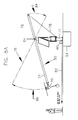
- FIG. 8 illustrates how the present invention can be erected in remote locations without using a crane and/or serviced without climbing pole 50 .
- HTS 16 is in its service position.
- Base pole 72 which may be approximately six to eight feet tall, is anchored into foundation 54 .
- Pole 50 which may be at least thirty feet long for most applications, is divided into top section 74 and bottom section 76 .
- the length of section 76 must be less than the height of base pole 72 .
- Pole 50 is attached with hinge 64 to the top of base pole 72 where sections 74 and 76 merge.
- Aerogenerator 20 is attached atop pole 50 , and cable 78 is attached to the bottom of pole 50 and extends from pole 50 under pulley 80 at the base of pole 72 and thence to a portable wench (not shown).
- cable 78 is pulled horizontally as indicated by arrow 82
- section 74 of pole 50 is pulled down as indicated by dotted arrow 84 until it is locked onto or inside base pole 72 .
- section 74 of pole 50 (and aerogenerator 20 ) is pulled up as indicated by dotted arrow 86 until pole 50 is perpendicular to foundation 54 and the HTS is erected and ready for use as illustrated in FIG. 8 b.
Abstract
Description
Claims (17)
Priority Applications (1)
| Application Number | Priority Date | Filing Date | Title |
|---|---|---|---|
| US12/927,101 US9774198B2 (en) | 2010-11-08 | 2010-11-08 | Wind and solar powered heat trace with homeostatic control |
Applications Claiming Priority (1)
| Application Number | Priority Date | Filing Date | Title |
|---|---|---|---|
| US12/927,101 US9774198B2 (en) | 2010-11-08 | 2010-11-08 | Wind and solar powered heat trace with homeostatic control |
Publications (2)
| Publication Number | Publication Date |
|---|---|
| US20120112546A1 US20120112546A1 (en) | 2012-05-10 |
| US9774198B2 true US9774198B2 (en) | 2017-09-26 |
Family
ID=46018928
Family Applications (1)
| Application Number | Title | Priority Date | Filing Date |
|---|---|---|---|
| US12/927,101 Expired - Fee Related US9774198B2 (en) | 2010-11-08 | 2010-11-08 | Wind and solar powered heat trace with homeostatic control |
Country Status (1)
| Country | Link |
|---|---|
| US (1) | US9774198B2 (en) |
Families Citing this family (20)
| Publication number | Priority date | Publication date | Assignee | Title |
|---|---|---|---|---|
| US20110168071A1 (en) * | 2007-02-08 | 2011-07-14 | Baruh Bradford G | System and method of adjusting the location and position of the foresail on a sailboat |
| US8432053B2 (en) * | 2009-06-15 | 2013-04-30 | Kevin E. Frayne | Wind turbine solar control system |
| EP2476898A4 (en) * | 2010-08-26 | 2014-08-06 | Alternative Energy Res Company Ltd | Method and solar-powered wind plant for producing electric power |
| US8847425B2 (en) * | 2012-04-04 | 2014-09-30 | Donnie E. JORDAN, SR. | Hybrid energy harvesting device and fixed threshold power production |
| CN102868206A (en) * | 2012-09-12 | 2013-01-09 | 北京工业大学 | Multi-clean-energy complementary type micro power station |
| WO2014123586A1 (en) | 2013-02-05 | 2014-08-14 | Jordan Donnie E | Hybrid energy harvesting device and fixed threshold power production |
| EP2796760A1 (en) * | 2013-04-23 | 2014-10-29 | Siemens Aktiengesellschaft | Direct electrical heating system |
| US9228370B1 (en) * | 2013-05-29 | 2016-01-05 | Anthony Peter Boniface | Tilt-down tower |
| JP6020480B2 (en) * | 2014-02-04 | 2016-11-02 | コニカミノルタ株式会社 | Power control apparatus and image forming apparatus |
| US9689758B2 (en) | 2014-05-07 | 2017-06-27 | Bode Energy Equipment Co., Ltd. | Solar battery wireless load cell |
| US9800198B2 (en) * | 2014-05-23 | 2017-10-24 | Rizwan Shoukat | Automatic intelligent hybrid electricity generating device |
| US9952073B2 (en) | 2014-11-19 | 2018-04-24 | Bode Energy Equipment Co., Ltd. | Solar battery wireless integrated load cell and inclinometer |
| KR102189479B1 (en) * | 2015-06-02 | 2020-12-11 | 엘에스일렉트릭(주) | A power supply apparatus |
| US9983076B2 (en) | 2015-08-18 | 2018-05-29 | Bode Energy Equipment Co., Ltd. | Solar battery wireless load cell adapter |
| DE102016115431A1 (en) * | 2016-08-19 | 2018-02-22 | Wobben Properties Gmbh | Method for controlling a wind energy plant |
| GB2560378B (en) * | 2017-03-10 | 2022-05-18 | Equinor Energy As | Power supply system for an offshore platform |
| US11867028B2 (en) | 2021-01-06 | 2024-01-09 | Saudi Arabian Oil Company | Gauge cutter and sampler apparatus |
| US11585176B2 (en) | 2021-03-23 | 2023-02-21 | Saudi Arabian Oil Company | Sealing cracked cement in a wellbore casing |
| US11867012B2 (en) | 2021-12-06 | 2024-01-09 | Saudi Arabian Oil Company | Gauge cutter and sampler apparatus |
| CN114838748B (en) * | 2022-05-06 | 2022-12-13 | 山东鸣迅智能科技有限公司 | Intelligent digital rural environment detection equipment based on big data |
Citations (148)
| Publication number | Priority date | Publication date | Assignee | Title |
|---|---|---|---|---|
| US2696566A (en) * | 1949-10-20 | 1954-12-07 | Kurt S Lion | Electric transducer system |
| US3132292A (en) * | 1959-06-03 | 1964-05-05 | Wm Ainsworth & Sons Inc | Phase compensating wheatstone bridge servosystem |
| US3292687A (en) * | 1964-06-15 | 1966-12-20 | James D Evans | Control means |
| US4158356A (en) * | 1977-02-22 | 1979-06-19 | Wininger David V | Self-powered tracking solar collector |
| US4182960A (en) * | 1978-05-30 | 1980-01-08 | Reuyl John S | Integrated residential and automotive energy system |
| US4206396A (en) * | 1977-08-29 | 1980-06-03 | Marks Alvin M | Charged aerosol generator with uni-electrode source |
| US4224082A (en) * | 1979-06-26 | 1980-09-23 | Independent Power Company, Inc. | Multi-functional solar collector pole |
| US4355195A (en) * | 1980-07-14 | 1982-10-19 | Ralph Sansbury | Electromagnetic solar cell |
| US4358929A (en) * | 1974-04-02 | 1982-11-16 | Stephen Molivadas | Solar power system |
| US4367403A (en) * | 1980-01-21 | 1983-01-04 | Rca Corporation | Array positioning system with out-of-focus solar cells |
| US4369629A (en) * | 1981-01-08 | 1983-01-25 | Lockwood Lawrence B | Natural energy extractor |
| US4441872A (en) * | 1981-04-14 | 1984-04-10 | Seale Joseph B | Fluid energy conversion system |
| US4551631A (en) * | 1984-07-06 | 1985-11-05 | Trigilio Gaetano T | Wind and solar electric generating plant |
| US4651017A (en) * | 1985-02-08 | 1987-03-17 | The United States Of America As Represented By The United States Department Of Energy | Wind energy conversion system |
| US4731547A (en) * | 1986-12-12 | 1988-03-15 | Caterpillar Inc. | Peak power shaving apparatus and method |
| US5075564A (en) * | 1989-12-19 | 1991-12-24 | Hickey John J | Combined solar and wind powered generator with spiral surface pattern |
| US5225712A (en) * | 1991-02-01 | 1993-07-06 | U.S. Windpower, Inc. | Variable speed wind turbine with reduced power fluctuation and a static VAR mode of operation |
| US5228924A (en) * | 1991-11-04 | 1993-07-20 | Mobil Solar Energy Corporation | Photovoltaic panel support assembly |
| US5254876A (en) * | 1992-05-28 | 1993-10-19 | Hickey John J | Combined solar and wind powered generator with spiral blades |
| US5293892A (en) * | 1992-10-20 | 1994-03-15 | Fourqurean George E | Solar powered injection device and method |
| US5334877A (en) * | 1991-02-25 | 1994-08-02 | Electric Power Research Institute | Standby power supply with load-current harmonics neutralizer |
| US5560700A (en) * | 1992-01-31 | 1996-10-01 | Massachusetts Institute Of Technology | Light coupler |
| US5686766A (en) * | 1994-04-12 | 1997-11-11 | Canon Kabushiki Kaisha | Islanding-operation prevention apparatus, and dispersed power generation apparatus and power generation system using the same |
| US5856712A (en) * | 1996-12-05 | 1999-01-05 | I-Hits Laboratory | Uninterruptible power supply method |
| US5982253A (en) * | 1997-08-27 | 1999-11-09 | Nartron Corporation | In-line module for attenuating electrical noise with male and female blade terminals |
| JP2000009879A (en) | 1998-06-29 | 2000-01-14 | Mitsubishi Heavy Ind Ltd | Safety system heat trace control device |
| US6032732A (en) * | 1998-04-27 | 2000-03-07 | Yewell; Ronald E. | Well head heating system |
| US6037749A (en) * | 1995-06-21 | 2000-03-14 | Batteryguard Limited | Battery monitor |
| US6060658A (en) * | 1996-12-19 | 2000-05-09 | Showa Pole Co., Ltd. | Pole having solar cells |
| US6067243A (en) * | 1996-06-06 | 2000-05-23 | I-Hits Laboratory Corporation | AC-AC/DC converter |
| US6080927A (en) * | 1994-09-15 | 2000-06-27 | Johnson; Colin Francis | Solar concentrator for heat and electricity |
| US6109029A (en) * | 1997-01-29 | 2000-08-29 | Vowles; Alan Keith | Wave energy converter |
| US6184593B1 (en) * | 1999-07-29 | 2001-02-06 | Abb Power T&D Company Inc. | Uninterruptible power supply |
| US6201371B1 (en) * | 1998-08-07 | 2001-03-13 | Matsushita Electric Industrial Co., Ltd. | Uninterruptible power system |
| US20010004170A1 (en) * | 1998-12-22 | 2001-06-21 | Schienbein Lawrence A. | Step wave power converter |
| US20010013703A1 (en) * | 2000-02-16 | 2001-08-16 | Valere Croes | Device for using wind power or generating wind and pitch system for such a device |
| US6288916B1 (en) * | 1999-10-15 | 2001-09-11 | Alpha Technologies, Inc. | Multiple output uninterruptible alternating current power supplies for communications system |
| US6296007B1 (en) * | 2001-02-14 | 2001-10-02 | Joseph Cifune | Heated valve for operation in freezing conditions |
| US6338381B1 (en) * | 2000-02-15 | 2002-01-15 | Mcclung, Iii Guy L. | Heat exchange systems |
| US20020066269A1 (en) * | 1996-11-14 | 2002-06-06 | Energetech Australia Pty. Limited | Ocean wave energy extraction system and components thereof |
| US20020084655A1 (en) * | 2000-12-29 | 2002-07-04 | Abb Research Ltd. | System, method and computer program product for enhancing commercial value of electrical power produced from a renewable energy power production facility |
| US6428694B1 (en) * | 1999-11-17 | 2002-08-06 | Komex H2O Science, Inc. | Solar powered environmental remediation devices |
| US6455954B1 (en) * | 2000-05-31 | 2002-09-24 | Innovations Electrical Lc | Auxiliary power supply system serving as primary power source during selected times and power outages |
| US20020195138A1 (en) * | 2001-06-01 | 2002-12-26 | Shigenori Itoyama | Solar-cell-installed structure, and photovoltaic power generation system |
| US20030047209A1 (en) * | 2001-08-31 | 2003-03-13 | Sanyo Electric Co., Ltd. | Photovoltaic power generation system with storage batteries |
| US6542791B1 (en) * | 1998-05-21 | 2003-04-01 | The Research Foundation Of State University Of New York | Load controller and method to enhance effective capacity of a photovotaic power supply using a dynamically determined expected peak loading |
| US20030076005A1 (en) * | 2001-07-10 | 2003-04-24 | Moreland John W. | Methods and apparatus to enhance electric currents |
| US20030117822A1 (en) * | 2001-12-26 | 2003-06-26 | Stamenic Ljubisav S. | Apparatus for regulating the delivery of power from a DC power source to an active or passive load |
| US20030116154A1 (en) * | 2001-06-22 | 2003-06-26 | Butler Barry Lynn | Method and system for controlling a solar collector |
| US20030121514A1 (en) * | 2001-06-22 | 2003-07-03 | Science Applications International Corporation | Method and system for controlling operation of an energy conversion device |
| US6602627B2 (en) * | 2000-03-20 | 2003-08-05 | Alpha Technologies, Inc. | Uninterruptible power supplies using fuel cells |
| US20030160454A1 (en) * | 2002-02-25 | 2003-08-28 | John Manolis | Renewabel gravity, wind and solar energy engine |
| US20030167105A1 (en) * | 2000-07-28 | 2003-09-04 | Colborn Jeffrey A. | System of and method for power management |
| US6616402B2 (en) * | 2001-06-14 | 2003-09-09 | Douglas Spriggs Selsam | Serpentine wind turbine |
| US6639328B2 (en) * | 2000-12-19 | 2003-10-28 | Capstone Turbine Corporation | Microturbine/capacitor power distribution system |
| US20030230333A1 (en) * | 2002-03-19 | 2003-12-18 | Ravindra Kashyap | Solar-paneled windmill |
| US20040044442A1 (en) * | 2001-12-28 | 2004-03-04 | Bayoumi Deia Salah-Eldin | Optimized dispatch planning of distributed resources in electrical power systems |
| JP2004103207A (en) | 2003-06-19 | 2004-04-02 | Pioneer Electronic Corp | Information recording medium and its reproducing apparatus, and reproducing method |
| US20040066094A1 (en) * | 2002-08-01 | 2004-04-08 | Yasunobu Suzuki | Co-generated power supply system |
| US6776227B2 (en) * | 2002-03-08 | 2004-08-17 | Rodney T. Beida | Wellhead heating apparatus and method |
| US6841971B1 (en) * | 2002-05-29 | 2005-01-11 | Alpha Technologies, Inc. | Charge balancing systems and methods |
| US20050063865A1 (en) * | 2002-09-27 | 2005-03-24 | Ulrich Bonne | Phased VII micro fluid analyzer having a modular structure |
| US6897370B2 (en) * | 2001-05-29 | 2005-05-24 | Canon Kabushiki Kaisha | Power generation apparatus and its control method |
| US7008171B1 (en) * | 2004-03-17 | 2006-03-07 | Circle Wind Corp. | Modified Savonius rotor |
| US20060087800A1 (en) * | 2004-10-27 | 2006-04-27 | Nextek Power Systems, Inc. | Portable hybrid applications for AC/DC load sharing |
| US7050312B2 (en) * | 2004-03-09 | 2006-05-23 | Eaton Power Quality Corporation | Multi-mode uninterruptible power supplies and methods of operation thereof |
| CA2497375A1 (en) | 2005-02-17 | 2006-08-17 | Curtis Squire | Solar powered heat trace system |
| US20060191902A1 (en) * | 2005-02-17 | 2006-08-31 | David Naylor | Modular heated cover |
| US20060207646A1 (en) * | 2003-07-07 | 2006-09-21 | Christine Terreau | Encapsulation of solar cells |
| US20060260672A1 (en) * | 2003-04-07 | 2006-11-23 | Robert Niederer | Supply unit for power and water based on renewable energy |
| US7151326B2 (en) * | 2003-09-23 | 2006-12-19 | Idle Free Systems, L.L.C. | System and method for safely and efficiently capturing power currently produced by already available power supplies to power electrical devices in a truck while its engine is turned off |
| US20070001460A1 (en) * | 2004-06-23 | 2007-01-04 | Energy & Engine Technology Corporation | Method and system for power generation |
| US20070040387A1 (en) * | 2005-06-09 | 2007-02-22 | Yehuda Roseman | Producing useful electricity from jetstreams |
| US20070100506A1 (en) * | 2005-10-31 | 2007-05-03 | Ralph Teichmann | System and method for controlling power flow of electric power generation system |
| US20070164571A1 (en) * | 2006-01-13 | 2007-07-19 | Industrial Technology Research Institute | Wind-tunnel type power generator |
| US20070164567A1 (en) * | 2006-01-19 | 2007-07-19 | General Electric Company | Wind turbine dump load system and method |
| US20070173982A1 (en) * | 2006-01-26 | 2007-07-26 | General Electric Company | Systems and methods for controlling a ramp rate of a wind farm |
| US20070170724A1 (en) * | 2006-01-20 | 2007-07-26 | Southwest Windpower, Inc. | Stall controller and triggering condition control features for a wind turbine |
| US20070182162A1 (en) * | 2005-07-27 | 2007-08-09 | Mcclintic Frank | Methods and apparatus for advanced windmill design |
| US20070182161A1 (en) * | 2006-02-06 | 2007-08-09 | Harjit Mann | Wind powered streetlight |
| US20070194575A1 (en) * | 2006-02-17 | 2007-08-23 | Kuang-Chieh Wu | Portable wind-driven electricity generation device |
| US20070194759A1 (en) * | 2006-02-17 | 2007-08-23 | Power Systems Co., Ltd. | Charging apparatus for capacitor storage type power source and discharging apparatus for capacitor storage type power source |
| US20070200348A1 (en) * | 2004-01-08 | 2007-08-30 | Hitachi, Ltd. | Wind Turbine Generator System |
| US20070235326A1 (en) * | 2006-03-29 | 2007-10-11 | Wen-Chang Lin | Solar-powered oxyhydrogen generating system |
| US20070246943A1 (en) * | 2006-04-25 | 2007-10-25 | The University Of New Brunswick | Stand-alone wind turbine system, apparatus, and method suitable for operating the same |
| US20070267874A1 (en) * | 2003-04-30 | 2007-11-22 | Ronald Taylor | Integrated power plant that utilizes renewable and alternative energy sources |
| US7309831B2 (en) * | 1998-10-13 | 2007-12-18 | Dai Nippon Printing Co., Ltd | Protective sheet for solar battery module, method of fabricating the same and solar battery module |
| US7345374B1 (en) * | 2005-02-25 | 2008-03-18 | World Factory, Inc. | Decorative windmill with solar panel |
| US20080079263A1 (en) * | 2006-09-28 | 2008-04-03 | Mahesh Amritlal Morjaria | Method and apparatus for operating wind turbine generators |
| US7385304B1 (en) * | 2006-09-18 | 2008-06-10 | Wohlert Troy B | Wind warning system |
| US20080150292A1 (en) * | 2006-12-21 | 2008-06-26 | Green Energy Technologies, Inc. | Shrouded wind turbine system with yaw control |
| CN201083112Y (en) | 2007-08-29 | 2008-07-09 | 辽宁华孚石油高科技股份有限公司 | Wind electricity oil well and pipeline heat tracing device |
| US20080258470A1 (en) * | 2007-04-12 | 2008-10-23 | Soon Eng Khoo | Energy Generation System For Housing, Commercial, and Industrial Applications |
| US7453167B2 (en) * | 2006-07-19 | 2008-11-18 | Micah Gilbert | Solar windmill |
| US20080285271A1 (en) * | 2007-05-04 | 2008-11-20 | Philips Solid-State Lighting Solutions, Inc. | Led-based fixtures and related methods for thermal management |
| US20080289352A1 (en) * | 2005-11-29 | 2008-11-27 | Marc Hugues Parent | Machine for Producing Water form Wind Energy |
| US7465873B2 (en) * | 2001-09-28 | 2008-12-16 | Kaneka Corporation | Solar cell module, method of laying solar cell modules, and apparatus for preventing solar cell modules from being blown off |
| US20090014057A1 (en) * | 2007-07-13 | 2009-01-15 | Miasole | Photovoltaic modules with integrated devices |
| US20090026771A1 (en) * | 2003-05-30 | 2009-01-29 | Northern Power Systems, Inc. | Wind Turbine Having a Direct-Drive Drivetrain |
| US20090026879A1 (en) * | 2005-10-25 | 2009-01-29 | Prelas Mark A | Micro-Scale Power Source |
| US20090028706A1 (en) * | 2007-07-26 | 2009-01-29 | Stefan Ioana | Vertical Axle Helix Monoblock Wind Turbine |
| US20090028705A1 (en) * | 2007-06-22 | 2009-01-29 | Gamesa Innovation & Technology, S.L. | Wind turbine blade with deflectable flaps |
| US20090032082A1 (en) * | 2007-08-03 | 2009-02-05 | Jack Arthur Gilmore | System, method, and apparatus for coupling photovoltaic arrays |
| US20090032089A1 (en) * | 2007-08-03 | 2009-02-05 | Atomic Energy Council - Institute Of Nuclear Energy Research | Solar tracker having louver frames |
| US20090032081A1 (en) * | 2007-08-02 | 2009-02-05 | Sanyo Electric Co., Ltd. | Solar cell module and method for manufacturing the same |
| US20090032084A1 (en) * | 2007-07-30 | 2009-02-05 | Emcore Corporation | Optimization of ground coverage of terrestrial solar array system |
| US20090038668A1 (en) * | 2007-08-08 | 2009-02-12 | Joshua Reed Plaisted | Topologies, systems and methods for control of solar energy supply systems |
| RU2350847C1 (en) | 2007-09-10 | 2009-03-27 | Российская Академия сельскохозяйственных наук Государственное научное учреждение Всероссийский научно-исследовательский институт электрификации сельского хозяйства (ГНУ ВИЭСХ РОССЕЛЬХОЗАКАДЕМИИ) | System for independent supply of heat to consumers relying on usage of low-potential heat source and powered from renewable electric energy sources |
| US20090108782A1 (en) * | 2007-10-26 | 2009-04-30 | Frederick William Klatt | Brushless Multiphase Self-Commutation Control (or BMSCC) And Related Inventions |
| US20090114264A1 (en) * | 2007-10-25 | 2009-05-07 | Gianrocco Giampietro | Fixed-geometry and/or variable-geometry surfaces for capturing solar energy by means of photovoltaic cells, films, and panels, in particular for watercraft |
| US20090119073A1 (en) * | 2007-11-05 | 2009-05-07 | Tyco Thermal Controls Llc | Heat trace system design |
| US20090133733A1 (en) * | 2007-11-27 | 2009-05-28 | Retti Kahrl L | Autonomous, modular power generation, storage and distribution apparatus, system and method thereof |
| US20090152867A1 (en) * | 2007-12-14 | 2009-06-18 | Cripps Jeffrey L | Self-sustaining electric power generating system |
| US20090160187A1 (en) * | 2007-12-19 | 2009-06-25 | Scholte-Wassink Hartmut | Control system and method for operating a wind farm in a balanced state |
| US20090160254A1 (en) * | 2007-12-19 | 2009-06-25 | American Power Conversion Corporation | Systems for and methods of controlling operation of a ups |
| USD595885S1 (en) * | 2009-01-21 | 2009-07-07 | Duggal Dimensions LLC | Wind and solar-powered light post |
| US20090174259A1 (en) * | 2008-01-09 | 2009-07-09 | Shan-Cheng Lin | Natural Energy Power Supplying Apparatus |
| US20090191057A1 (en) * | 2008-01-24 | 2009-07-30 | Knutson Roger C | Multi-Axis Wind Turbine With Power Concentrator Sail |
| US20090200808A1 (en) * | 2006-02-25 | 2009-08-13 | Parmley Sr Daniel W | Pole-mountable wind turbine support system |
| US20090200807A1 (en) * | 2008-02-08 | 2009-08-13 | Wil Adams | Adams alternative energy system |
| US20090200804A1 (en) * | 2006-10-24 | 2009-08-13 | Thomas Steiniche Bjertrup Nielsen | Method For Damping Tower Oscillations, An Active Stall Controlled Wind Turbine And Use Hereof |
| US20090200803A1 (en) * | 2008-02-08 | 2009-08-13 | Masaya Ichinose | Wind power generation system |
| US20090206607A1 (en) * | 2008-02-15 | 2009-08-20 | Seiko Epson Corporation | Power generator and motor device |
| US20090206606A1 (en) * | 2007-12-28 | 2009-08-20 | Vestas Wind Systems A/S | Variable Speed Wind Turbine Configured For Wind Farm Operation |
| US20090206610A1 (en) * | 2008-02-15 | 2009-08-20 | Negel Martin | Cable guard and method of installation |
| US20090206603A1 (en) * | 2005-07-22 | 2009-08-20 | Jose Ignacio Llorente Gonzalez | Method of maintaining wind turbine components operational and a turbine comprising components suitable for operational maintenace |
| US20090206604A1 (en) * | 2008-02-15 | 2009-08-20 | Karl-Heinz Meiners | Method of transporting bulky equipment of a wind power plant, preassembled equipment |
| US20090206605A1 (en) * | 2008-02-16 | 2009-08-20 | Nordex Energy Gmbh | Method for the operation of a wind energy plant |
| US20090205247A1 (en) * | 2004-09-24 | 2009-08-20 | Aloys Wobben | Regenerative energy system |
| US20090295162A1 (en) * | 2007-09-27 | 2009-12-03 | Hitachi Engineering & Services Co., Ltd. | Wind power generation system of a type provided with power storage system |
| US20090307178A1 (en) * | 2006-05-26 | 2009-12-10 | Hampden Kuhns | Utility monitoring systems and methods of use |
| US20100045042A1 (en) * | 2008-08-19 | 2010-02-25 | Hinders Edward B | Renewable Energy Electric Generating System |
| US20100090463A1 (en) * | 2008-10-10 | 2010-04-15 | Jacob Johannes Nies | Combined environmental monitoring and power supply device |
| US20100150718A1 (en) * | 2007-12-10 | 2010-06-17 | Freda Robert M | Efficient systems and methods for construction and operation of accelerating machines |
| US7750503B2 (en) * | 2005-03-30 | 2010-07-06 | Honda Motor Co., Ltd. | Direct current stabilizing power source apparatus |
| US20100176602A1 (en) * | 2007-03-08 | 2010-07-15 | Reuel Shinnar | Solar power plant and method and/or system of storing energy in a concentrated solar power plant |
| US7768153B2 (en) * | 2005-09-26 | 2010-08-03 | Chicony Power Technology Co., Ltd. | Dual input power supply |
| US7780852B2 (en) * | 2003-07-24 | 2010-08-24 | Effusion Dynamics, Llc | Method for converting kinetic energy of gases or liquids to useful energy, force and work |
| US20100229916A1 (en) * | 2009-03-12 | 2010-09-16 | Geraldine Bechamp | Protection system |
| US7802426B2 (en) * | 2008-06-09 | 2010-09-28 | Sustainx, Inc. | System and method for rapid isothermal gas expansion and compression for energy storage |
| USRE41965E1 (en) * | 2003-08-22 | 2010-11-30 | Xantrex Technology Inc. | Bi-directional multi-port inverter with high frequency link transformer |
| US8097926B2 (en) * | 2008-10-07 | 2012-01-17 | Mc10, Inc. | Systems, methods, and devices having stretchable integrated circuitry for sensing and delivering therapy |
| US8103389B2 (en) * | 2006-05-18 | 2012-01-24 | Gridpoint, Inc. | Modular energy control system |
| US8174136B2 (en) * | 2006-04-26 | 2012-05-08 | Alliance For Sustainable Energy, Llc | Adaptive pitch control for variable speed wind turbines |
| US8299645B2 (en) * | 2007-07-27 | 2012-10-30 | Skybuilt Power | Renewable energy trailer |
| US8420926B1 (en) * | 2007-10-02 | 2013-04-16 | University Of Central Florida Research Foundation, Inc. | Hybrid solar cell integrating photovoltaic and thermoelectric cell elements for high efficiency and longevity |
| US8421263B2 (en) * | 2010-10-27 | 2013-04-16 | Florida Turbine Technologies, Inc. | Floating vertical axis wind turbine |
| US8421257B2 (en) * | 2009-03-11 | 2013-04-16 | Dimitri Chernyshov | Tethered glider system for power generation |
-
2010
- 2010-11-08 US US12/927,101 patent/US9774198B2/en not_active Expired - Fee Related
Patent Citations (169)
| Publication number | Priority date | Publication date | Assignee | Title |
|---|---|---|---|---|
| US2696566A (en) * | 1949-10-20 | 1954-12-07 | Kurt S Lion | Electric transducer system |
| US3132292A (en) * | 1959-06-03 | 1964-05-05 | Wm Ainsworth & Sons Inc | Phase compensating wheatstone bridge servosystem |
| US3292687A (en) * | 1964-06-15 | 1966-12-20 | James D Evans | Control means |
| US4358929A (en) * | 1974-04-02 | 1982-11-16 | Stephen Molivadas | Solar power system |
| US4158356A (en) * | 1977-02-22 | 1979-06-19 | Wininger David V | Self-powered tracking solar collector |
| US4206396A (en) * | 1977-08-29 | 1980-06-03 | Marks Alvin M | Charged aerosol generator with uni-electrode source |
| US4182960A (en) * | 1978-05-30 | 1980-01-08 | Reuyl John S | Integrated residential and automotive energy system |
| US4224082A (en) * | 1979-06-26 | 1980-09-23 | Independent Power Company, Inc. | Multi-functional solar collector pole |
| US4367403A (en) * | 1980-01-21 | 1983-01-04 | Rca Corporation | Array positioning system with out-of-focus solar cells |
| US4355195A (en) * | 1980-07-14 | 1982-10-19 | Ralph Sansbury | Electromagnetic solar cell |
| US4369629A (en) * | 1981-01-08 | 1983-01-25 | Lockwood Lawrence B | Natural energy extractor |
| US4441872A (en) * | 1981-04-14 | 1984-04-10 | Seale Joseph B | Fluid energy conversion system |
| US4551631A (en) * | 1984-07-06 | 1985-11-05 | Trigilio Gaetano T | Wind and solar electric generating plant |
| US4651017A (en) * | 1985-02-08 | 1987-03-17 | The United States Of America As Represented By The United States Department Of Energy | Wind energy conversion system |
| US4731547A (en) * | 1986-12-12 | 1988-03-15 | Caterpillar Inc. | Peak power shaving apparatus and method |
| US5075564A (en) * | 1989-12-19 | 1991-12-24 | Hickey John J | Combined solar and wind powered generator with spiral surface pattern |
| US5225712A (en) * | 1991-02-01 | 1993-07-06 | U.S. Windpower, Inc. | Variable speed wind turbine with reduced power fluctuation and a static VAR mode of operation |
| US5334877A (en) * | 1991-02-25 | 1994-08-02 | Electric Power Research Institute | Standby power supply with load-current harmonics neutralizer |
| US5228924A (en) * | 1991-11-04 | 1993-07-20 | Mobil Solar Energy Corporation | Photovoltaic panel support assembly |
| US5560700A (en) * | 1992-01-31 | 1996-10-01 | Massachusetts Institute Of Technology | Light coupler |
| US5254876A (en) * | 1992-05-28 | 1993-10-19 | Hickey John J | Combined solar and wind powered generator with spiral blades |
| US5293892A (en) * | 1992-10-20 | 1994-03-15 | Fourqurean George E | Solar powered injection device and method |
| US5686766A (en) * | 1994-04-12 | 1997-11-11 | Canon Kabushiki Kaisha | Islanding-operation prevention apparatus, and dispersed power generation apparatus and power generation system using the same |
| US6080927A (en) * | 1994-09-15 | 2000-06-27 | Johnson; Colin Francis | Solar concentrator for heat and electricity |
| US6037749A (en) * | 1995-06-21 | 2000-03-14 | Batteryguard Limited | Battery monitor |
| US6067243A (en) * | 1996-06-06 | 2000-05-23 | I-Hits Laboratory Corporation | AC-AC/DC converter |
| US20020066269A1 (en) * | 1996-11-14 | 2002-06-06 | Energetech Australia Pty. Limited | Ocean wave energy extraction system and components thereof |
| US5856712A (en) * | 1996-12-05 | 1999-01-05 | I-Hits Laboratory | Uninterruptible power supply method |
| US6060658A (en) * | 1996-12-19 | 2000-05-09 | Showa Pole Co., Ltd. | Pole having solar cells |
| US6109029A (en) * | 1997-01-29 | 2000-08-29 | Vowles; Alan Keith | Wave energy converter |
| US5982253A (en) * | 1997-08-27 | 1999-11-09 | Nartron Corporation | In-line module for attenuating electrical noise with male and female blade terminals |
| US6032732A (en) * | 1998-04-27 | 2000-03-07 | Yewell; Ronald E. | Well head heating system |
| US6542791B1 (en) * | 1998-05-21 | 2003-04-01 | The Research Foundation Of State University Of New York | Load controller and method to enhance effective capacity of a photovotaic power supply using a dynamically determined expected peak loading |
| JP2000009879A (en) | 1998-06-29 | 2000-01-14 | Mitsubishi Heavy Ind Ltd | Safety system heat trace control device |
| US6201371B1 (en) * | 1998-08-07 | 2001-03-13 | Matsushita Electric Industrial Co., Ltd. | Uninterruptible power system |
| US7309831B2 (en) * | 1998-10-13 | 2007-12-18 | Dai Nippon Printing Co., Ltd | Protective sheet for solar battery module, method of fabricating the same and solar battery module |
| US20010004170A1 (en) * | 1998-12-22 | 2001-06-21 | Schienbein Lawrence A. | Step wave power converter |
| US6608404B2 (en) * | 1998-12-22 | 2003-08-19 | International Power Systems, Inc. | Step wave power converter |
| US6184593B1 (en) * | 1999-07-29 | 2001-02-06 | Abb Power T&D Company Inc. | Uninterruptible power supply |
| US6288916B1 (en) * | 1999-10-15 | 2001-09-11 | Alpha Technologies, Inc. | Multiple output uninterruptible alternating current power supplies for communications system |
| US6428694B1 (en) * | 1999-11-17 | 2002-08-06 | Komex H2O Science, Inc. | Solar powered environmental remediation devices |
| US6338381B1 (en) * | 2000-02-15 | 2002-01-15 | Mcclung, Iii Guy L. | Heat exchange systems |
| US20010013703A1 (en) * | 2000-02-16 | 2001-08-16 | Valere Croes | Device for using wind power or generating wind and pitch system for such a device |
| US6602627B2 (en) * | 2000-03-20 | 2003-08-05 | Alpha Technologies, Inc. | Uninterruptible power supplies using fuel cells |
| US6455954B1 (en) * | 2000-05-31 | 2002-09-24 | Innovations Electrical Lc | Auxiliary power supply system serving as primary power source during selected times and power outages |
| US20030167105A1 (en) * | 2000-07-28 | 2003-09-04 | Colborn Jeffrey A. | System of and method for power management |
| US6639328B2 (en) * | 2000-12-19 | 2003-10-28 | Capstone Turbine Corporation | Microturbine/capacitor power distribution system |
| US6512966B2 (en) * | 2000-12-29 | 2003-01-28 | Abb Ab | System, method and computer program product for enhancing commercial value of electrical power produced from a renewable energy power production facility |
| US20050127680A1 (en) * | 2000-12-29 | 2005-06-16 | Abb Ab | System, method and computer program product for enhancing commercial value of electrical power produced from a renewable energy power production facility |
| US20030006613A1 (en) * | 2000-12-29 | 2003-01-09 | Abb Ab | System, method and computer program product for enhancing commercial value of electrical power produced from a renewable energy power production facility |
| US20020084655A1 (en) * | 2000-12-29 | 2002-07-04 | Abb Research Ltd. | System, method and computer program product for enhancing commercial value of electrical power produced from a renewable energy power production facility |
| US6296007B1 (en) * | 2001-02-14 | 2001-10-02 | Joseph Cifune | Heated valve for operation in freezing conditions |
| US6897370B2 (en) * | 2001-05-29 | 2005-05-24 | Canon Kabushiki Kaisha | Power generation apparatus and its control method |
| US6803515B2 (en) * | 2001-06-01 | 2004-10-12 | Canon Kabushiki Kaisha | Solar-cell-installed structure, and photovoltaic power generation system |
| US20020195138A1 (en) * | 2001-06-01 | 2002-12-26 | Shigenori Itoyama | Solar-cell-installed structure, and photovoltaic power generation system |
| US6616402B2 (en) * | 2001-06-14 | 2003-09-09 | Douglas Spriggs Selsam | Serpentine wind turbine |
| US20030121514A1 (en) * | 2001-06-22 | 2003-07-03 | Science Applications International Corporation | Method and system for controlling operation of an energy conversion device |
| US6688303B2 (en) * | 2001-06-22 | 2004-02-10 | Science Applications International Corporation | Method and system for controlling operation of an energy conversion device |
| US20030116154A1 (en) * | 2001-06-22 | 2003-06-26 | Butler Barry Lynn | Method and system for controlling a solar collector |
| US20030076005A1 (en) * | 2001-07-10 | 2003-04-24 | Moreland John W. | Methods and apparatus to enhance electric currents |
| US20030047209A1 (en) * | 2001-08-31 | 2003-03-13 | Sanyo Electric Co., Ltd. | Photovoltaic power generation system with storage batteries |
| US7465873B2 (en) * | 2001-09-28 | 2008-12-16 | Kaneka Corporation | Solar cell module, method of laying solar cell modules, and apparatus for preventing solar cell modules from being blown off |
| US20030117822A1 (en) * | 2001-12-26 | 2003-06-26 | Stamenic Ljubisav S. | Apparatus for regulating the delivery of power from a DC power source to an active or passive load |
| US20040044442A1 (en) * | 2001-12-28 | 2004-03-04 | Bayoumi Deia Salah-Eldin | Optimized dispatch planning of distributed resources in electrical power systems |
| US20030160454A1 (en) * | 2002-02-25 | 2003-08-28 | John Manolis | Renewabel gravity, wind and solar energy engine |
| US6776227B2 (en) * | 2002-03-08 | 2004-08-17 | Rodney T. Beida | Wellhead heating apparatus and method |
| US7045702B2 (en) * | 2002-03-19 | 2006-05-16 | Ravindra Kashyap | Solar-paneled windmill |
| US20030230333A1 (en) * | 2002-03-19 | 2003-12-18 | Ravindra Kashyap | Solar-paneled windmill |
| US6841971B1 (en) * | 2002-05-29 | 2005-01-11 | Alpha Technologies, Inc. | Charge balancing systems and methods |
| US7449798B2 (en) * | 2002-08-01 | 2008-11-11 | I-Hits Laboratory | Co-generated power supply system |
| US20090085404A1 (en) * | 2002-08-01 | 2009-04-02 | Yasunobu Suzuki | Co-generated power supply system |
| US20040066094A1 (en) * | 2002-08-01 | 2004-04-08 | Yasunobu Suzuki | Co-generated power supply system |
| US20050063865A1 (en) * | 2002-09-27 | 2005-03-24 | Ulrich Bonne | Phased VII micro fluid analyzer having a modular structure |
| US20060260672A1 (en) * | 2003-04-07 | 2006-11-23 | Robert Niederer | Supply unit for power and water based on renewable energy |
| US20070267874A1 (en) * | 2003-04-30 | 2007-11-22 | Ronald Taylor | Integrated power plant that utilizes renewable and alternative energy sources |
| US7759812B2 (en) * | 2003-04-30 | 2010-07-20 | Terra Moya Aqua, Inc. | Integrated power plant that utilizes renewable and alternative energy sources |
| US20090026771A1 (en) * | 2003-05-30 | 2009-01-29 | Northern Power Systems, Inc. | Wind Turbine Having a Direct-Drive Drivetrain |
| JP2004103207A (en) | 2003-06-19 | 2004-04-02 | Pioneer Electronic Corp | Information recording medium and its reproducing apparatus, and reproducing method |
| US20060207646A1 (en) * | 2003-07-07 | 2006-09-21 | Christine Terreau | Encapsulation of solar cells |
| US7780852B2 (en) * | 2003-07-24 | 2010-08-24 | Effusion Dynamics, Llc | Method for converting kinetic energy of gases or liquids to useful energy, force and work |
| USRE41965E1 (en) * | 2003-08-22 | 2010-11-30 | Xantrex Technology Inc. | Bi-directional multi-port inverter with high frequency link transformer |
| US7151326B2 (en) * | 2003-09-23 | 2006-12-19 | Idle Free Systems, L.L.C. | System and method for safely and efficiently capturing power currently produced by already available power supplies to power electrical devices in a truck while its engine is turned off |
| US20070200348A1 (en) * | 2004-01-08 | 2007-08-30 | Hitachi, Ltd. | Wind Turbine Generator System |
| US7050312B2 (en) * | 2004-03-09 | 2006-05-23 | Eaton Power Quality Corporation | Multi-mode uninterruptible power supplies and methods of operation thereof |
| US7008171B1 (en) * | 2004-03-17 | 2006-03-07 | Circle Wind Corp. | Modified Savonius rotor |
| US20070001460A1 (en) * | 2004-06-23 | 2007-01-04 | Energy & Engine Technology Corporation | Method and system for power generation |
| US20090205247A1 (en) * | 2004-09-24 | 2009-08-20 | Aloys Wobben | Regenerative energy system |
| US20060087800A1 (en) * | 2004-10-27 | 2006-04-27 | Nextek Power Systems, Inc. | Portable hybrid applications for AC/DC load sharing |
| US7701083B2 (en) * | 2004-10-27 | 2010-04-20 | Nextek Power Systems, Inc. | Portable hybrid applications for AC/DC load sharing |
| US20060191902A1 (en) * | 2005-02-17 | 2006-08-31 | David Naylor | Modular heated cover |
| US7230213B2 (en) * | 2005-02-17 | 2007-06-12 | David Naylor | Modular heated cover |
| CA2497375A1 (en) | 2005-02-17 | 2006-08-17 | Curtis Squire | Solar powered heat trace system |
| US7345374B1 (en) * | 2005-02-25 | 2008-03-18 | World Factory, Inc. | Decorative windmill with solar panel |
| US7750503B2 (en) * | 2005-03-30 | 2010-07-06 | Honda Motor Co., Ltd. | Direct current stabilizing power source apparatus |
| US20070040387A1 (en) * | 2005-06-09 | 2007-02-22 | Yehuda Roseman | Producing useful electricity from jetstreams |
| US20090206603A1 (en) * | 2005-07-22 | 2009-08-20 | Jose Ignacio Llorente Gonzalez | Method of maintaining wind turbine components operational and a turbine comprising components suitable for operational maintenace |
| US20070182162A1 (en) * | 2005-07-27 | 2007-08-09 | Mcclintic Frank | Methods and apparatus for advanced windmill design |
| US7768153B2 (en) * | 2005-09-26 | 2010-08-03 | Chicony Power Technology Co., Ltd. | Dual input power supply |
| US20090026879A1 (en) * | 2005-10-25 | 2009-01-29 | Prelas Mark A | Micro-Scale Power Source |
| US20070100506A1 (en) * | 2005-10-31 | 2007-05-03 | Ralph Teichmann | System and method for controlling power flow of electric power generation system |
| US20080289352A1 (en) * | 2005-11-29 | 2008-11-27 | Marc Hugues Parent | Machine for Producing Water form Wind Energy |
| US20070164571A1 (en) * | 2006-01-13 | 2007-07-19 | Industrial Technology Research Institute | Wind-tunnel type power generator |
| US20070164567A1 (en) * | 2006-01-19 | 2007-07-19 | General Electric Company | Wind turbine dump load system and method |
| US20070170724A1 (en) * | 2006-01-20 | 2007-07-26 | Southwest Windpower, Inc. | Stall controller and triggering condition control features for a wind turbine |
| US20070173982A1 (en) * | 2006-01-26 | 2007-07-26 | General Electric Company | Systems and methods for controlling a ramp rate of a wind farm |
| US20070182161A1 (en) * | 2006-02-06 | 2007-08-09 | Harjit Mann | Wind powered streetlight |
| US20070194759A1 (en) * | 2006-02-17 | 2007-08-23 | Power Systems Co., Ltd. | Charging apparatus for capacitor storage type power source and discharging apparatus for capacitor storage type power source |
| US20070194575A1 (en) * | 2006-02-17 | 2007-08-23 | Kuang-Chieh Wu | Portable wind-driven electricity generation device |
| US20090200808A1 (en) * | 2006-02-25 | 2009-08-13 | Parmley Sr Daniel W | Pole-mountable wind turbine support system |
| US20070235326A1 (en) * | 2006-03-29 | 2007-10-11 | Wen-Chang Lin | Solar-powered oxyhydrogen generating system |
| US20070246943A1 (en) * | 2006-04-25 | 2007-10-25 | The University Of New Brunswick | Stand-alone wind turbine system, apparatus, and method suitable for operating the same |
| US7476987B2 (en) * | 2006-04-25 | 2009-01-13 | The University Of New Brunswick | Stand-alone wind turbine system, apparatus, and method suitable for operating the same |
| US8174136B2 (en) * | 2006-04-26 | 2012-05-08 | Alliance For Sustainable Energy, Llc | Adaptive pitch control for variable speed wind turbines |
| US8103389B2 (en) * | 2006-05-18 | 2012-01-24 | Gridpoint, Inc. | Modular energy control system |
| US8396821B2 (en) * | 2006-05-26 | 2013-03-12 | Board Of Regents Of The Nevada System Of Higher Education, On Behalf Of The Desert Research Institute | Utility monitoring systems and methods of use |
| US20090307178A1 (en) * | 2006-05-26 | 2009-12-10 | Hampden Kuhns | Utility monitoring systems and methods of use |
| US7885917B2 (en) * | 2006-05-26 | 2011-02-08 | Board Of Regents Of The Nevada System Of Higher Education, On Behalf Of The Desert Research Institute | Utility monitoring and disaggregation systems and methods of use |
| US7453167B2 (en) * | 2006-07-19 | 2008-11-18 | Micah Gilbert | Solar windmill |
| US7385304B1 (en) * | 2006-09-18 | 2008-06-10 | Wohlert Troy B | Wind warning system |
| US20080079263A1 (en) * | 2006-09-28 | 2008-04-03 | Mahesh Amritlal Morjaria | Method and apparatus for operating wind turbine generators |
| US7523001B2 (en) * | 2006-09-28 | 2009-04-21 | General Electric Company | Method and apparatus for operating wind turbine generators |
| US20090200804A1 (en) * | 2006-10-24 | 2009-08-13 | Thomas Steiniche Bjertrup Nielsen | Method For Damping Tower Oscillations, An Active Stall Controlled Wind Turbine And Use Hereof |
| US20080150292A1 (en) * | 2006-12-21 | 2008-06-26 | Green Energy Technologies, Inc. | Shrouded wind turbine system with yaw control |
| US7954321B2 (en) * | 2007-03-08 | 2011-06-07 | Research Foundation Of The City University Of New York | Solar power plant and method and/or system of storing energy in a concentrated solar power plant |
| US20100176602A1 (en) * | 2007-03-08 | 2010-07-15 | Reuel Shinnar | Solar power plant and method and/or system of storing energy in a concentrated solar power plant |
| US20110277471A1 (en) * | 2007-03-08 | 2011-11-17 | Research Foundation Of The City University Of New York | Solar power plant and method and/or system of storing energy in a concentrated solar power plant |
| US20080258470A1 (en) * | 2007-04-12 | 2008-10-23 | Soon Eng Khoo | Energy Generation System For Housing, Commercial, and Industrial Applications |
| US20080285271A1 (en) * | 2007-05-04 | 2008-11-20 | Philips Solid-State Lighting Solutions, Inc. | Led-based fixtures and related methods for thermal management |
| US20090028705A1 (en) * | 2007-06-22 | 2009-01-29 | Gamesa Innovation & Technology, S.L. | Wind turbine blade with deflectable flaps |
| US20090014057A1 (en) * | 2007-07-13 | 2009-01-15 | Miasole | Photovoltaic modules with integrated devices |
| US20090028706A1 (en) * | 2007-07-26 | 2009-01-29 | Stefan Ioana | Vertical Axle Helix Monoblock Wind Turbine |
| US8299645B2 (en) * | 2007-07-27 | 2012-10-30 | Skybuilt Power | Renewable energy trailer |
| US20090032084A1 (en) * | 2007-07-30 | 2009-02-05 | Emcore Corporation | Optimization of ground coverage of terrestrial solar array system |
| US20090032081A1 (en) * | 2007-08-02 | 2009-02-05 | Sanyo Electric Co., Ltd. | Solar cell module and method for manufacturing the same |
| US20090032089A1 (en) * | 2007-08-03 | 2009-02-05 | Atomic Energy Council - Institute Of Nuclear Energy Research | Solar tracker having louver frames |
| US20090032082A1 (en) * | 2007-08-03 | 2009-02-05 | Jack Arthur Gilmore | System, method, and apparatus for coupling photovoltaic arrays |
| US20090038668A1 (en) * | 2007-08-08 | 2009-02-12 | Joshua Reed Plaisted | Topologies, systems and methods for control of solar energy supply systems |
| CN201083112Y (en) | 2007-08-29 | 2008-07-09 | 辽宁华孚石油高科技股份有限公司 | Wind electricity oil well and pipeline heat tracing device |
| RU2350847C1 (en) | 2007-09-10 | 2009-03-27 | Российская Академия сельскохозяйственных наук Государственное научное учреждение Всероссийский научно-исследовательский институт электрификации сельского хозяйства (ГНУ ВИЭСХ РОССЕЛЬХОЗАКАДЕМИИ) | System for independent supply of heat to consumers relying on usage of low-potential heat source and powered from renewable electric energy sources |
| US20090295162A1 (en) * | 2007-09-27 | 2009-12-03 | Hitachi Engineering & Services Co., Ltd. | Wind power generation system of a type provided with power storage system |
| US8420926B1 (en) * | 2007-10-02 | 2013-04-16 | University Of Central Florida Research Foundation, Inc. | Hybrid solar cell integrating photovoltaic and thermoelectric cell elements for high efficiency and longevity |
| US20090114264A1 (en) * | 2007-10-25 | 2009-05-07 | Gianrocco Giampietro | Fixed-geometry and/or variable-geometry surfaces for capturing solar energy by means of photovoltaic cells, films, and panels, in particular for watercraft |
| US20100147605A1 (en) * | 2007-10-26 | 2010-06-17 | Frederick William Klatt | Brushless Multiphase Self-Commutation Control (or BMSCC) and Related Inventions |
| US20090108782A1 (en) * | 2007-10-26 | 2009-04-30 | Frederick William Klatt | Brushless Multiphase Self-Commutation Control (or BMSCC) And Related Inventions |
| US20090119073A1 (en) * | 2007-11-05 | 2009-05-07 | Tyco Thermal Controls Llc | Heat trace system design |
| US20090133733A1 (en) * | 2007-11-27 | 2009-05-28 | Retti Kahrl L | Autonomous, modular power generation, storage and distribution apparatus, system and method thereof |
| US20100150718A1 (en) * | 2007-12-10 | 2010-06-17 | Freda Robert M | Efficient systems and methods for construction and operation of accelerating machines |
| US20090152867A1 (en) * | 2007-12-14 | 2009-06-18 | Cripps Jeffrey L | Self-sustaining electric power generating system |
| US20090160254A1 (en) * | 2007-12-19 | 2009-06-25 | American Power Conversion Corporation | Systems for and methods of controlling operation of a ups |
| US20090160187A1 (en) * | 2007-12-19 | 2009-06-25 | Scholte-Wassink Hartmut | Control system and method for operating a wind farm in a balanced state |
| US7615891B2 (en) * | 2007-12-19 | 2009-11-10 | American Power Conversion Corporation | Systems for and methods of controlling operation of a UPS |
| US20090206606A1 (en) * | 2007-12-28 | 2009-08-20 | Vestas Wind Systems A/S | Variable Speed Wind Turbine Configured For Wind Farm Operation |
| US20090174259A1 (en) * | 2008-01-09 | 2009-07-09 | Shan-Cheng Lin | Natural Energy Power Supplying Apparatus |
| US20090191057A1 (en) * | 2008-01-24 | 2009-07-30 | Knutson Roger C | Multi-Axis Wind Turbine With Power Concentrator Sail |
| US20090200803A1 (en) * | 2008-02-08 | 2009-08-13 | Masaya Ichinose | Wind power generation system |
| US20090200807A1 (en) * | 2008-02-08 | 2009-08-13 | Wil Adams | Adams alternative energy system |
| US20090206610A1 (en) * | 2008-02-15 | 2009-08-20 | Negel Martin | Cable guard and method of installation |
| US20090206607A1 (en) * | 2008-02-15 | 2009-08-20 | Seiko Epson Corporation | Power generator and motor device |
| US20090206604A1 (en) * | 2008-02-15 | 2009-08-20 | Karl-Heinz Meiners | Method of transporting bulky equipment of a wind power plant, preassembled equipment |
| US20090206605A1 (en) * | 2008-02-16 | 2009-08-20 | Nordex Energy Gmbh | Method for the operation of a wind energy plant |
| US7802426B2 (en) * | 2008-06-09 | 2010-09-28 | Sustainx, Inc. | System and method for rapid isothermal gas expansion and compression for energy storage |
| US20100043435A1 (en) * | 2008-08-19 | 2010-02-25 | Hinders Edward B | Methods for Enhancing Efficiency of Steam-Based Generating Systems |
| US20100045042A1 (en) * | 2008-08-19 | 2010-02-25 | Hinders Edward B | Renewable Energy Electric Generating System |
| US8097926B2 (en) * | 2008-10-07 | 2012-01-17 | Mc10, Inc. | Systems, methods, and devices having stretchable integrated circuitry for sensing and delivering therapy |
| US20100090463A1 (en) * | 2008-10-10 | 2010-04-15 | Jacob Johannes Nies | Combined environmental monitoring and power supply device |
| USD595885S1 (en) * | 2009-01-21 | 2009-07-07 | Duggal Dimensions LLC | Wind and solar-powered light post |
| US8421257B2 (en) * | 2009-03-11 | 2013-04-16 | Dimitri Chernyshov | Tethered glider system for power generation |
| US20100229916A1 (en) * | 2009-03-12 | 2010-09-16 | Geraldine Bechamp | Protection system |
| US8421263B2 (en) * | 2010-10-27 | 2013-04-16 | Florida Turbine Technologies, Inc. | Floating vertical axis wind turbine |
Also Published As
| Publication number | Publication date |
|---|---|
| US20120112546A1 (en) | 2012-05-10 |
Similar Documents
| Publication | Publication Date | Title |
|---|---|---|
| US9774198B2 (en) | Wind and solar powered heat trace with homeostatic control | |
| US10193346B2 (en) | Interface for renewable energy system | |
| US9876360B2 (en) | Interface for renewable energy system | |
| KR100926959B1 (en) | Hybrid Power Generation and Management System for Buoys Using Photovoltaic, Wind, and Wave Power | |
| US10833629B2 (en) | Interface for renewable energy system | |
| US8648495B2 (en) | Smart-grid combination power system | |
| US7932621B1 (en) | Method and apparatus for an integrated wind-solar energy system utilizing an existing wind turbine infrastructure | |
| CN102812610B (en) | Control apparatus and control method | |
| EP2083610A2 (en) | Dual climate zones | |
| JP2015061511A (en) | System and method for minimizing power grid spinning reserve losses by preemptively controlling power generation equipment to offset wind power generation capacity based on geospatial regional wind conditions | |
| Misak et al. | Off-grid power systems | |
| CN103140670A (en) | Wind farm and method for operating a wind farm | |
| US11070165B2 (en) | Autonomous and movable device for generating, storing and distributing electrical power to dedicated movable batteries | |
| CN108475919A (en) | Mobile electrical power generates and regulating system | |
| RU113886U1 (en) | ENERGY-SUPPORTING COMPLEX BASED ON ALTERNATIVE ENERGY SOURCES | |
| McDowall | Energy storage in remote arctic communities: Driving down diesel consumption with batteries | |
| CN204244173U (en) | A kind of integrated control unit being applied to distributed photovoltaic power generation system | |
| Al-enezi et al. | Hybrid solar wind diesel power generation system | |
| WO2022243909A1 (en) | Hybrid system for the generation of electrical power | |
| CN107681676A (en) | A kind of fixed energy-accumulating power station system | |
| Manolea et al. | Contributions to the Development of Complementary Equipment for the Romanian Anti-Hail System | |
| US20140077751A1 (en) | Modular electrical energy production device | |
| CN208209542U (en) | A kind of distributed battery accumulation power supply system | |
| CN205141806U (en) | Independent solar energy power generation system | |
| CN115622501A (en) | Photovoltaic power supply and local control system of heliostat |
Legal Events
| Date | Code | Title | Description |
|---|---|---|---|
| AS | Assignment |
Owner name: CULVER INDUSTRIES, LLC, OKLAHOMA Free format text: ASSIGNMENT OF ASSIGNORS INTEREST;ASSIGNOR:CULVER, BRANDON;REEL/FRAME:025642/0467 Effective date: 20101011 |
|
| STCF | Information on status: patent grant |
Free format text: PATENTED CASE |
|
| FEPP | Fee payment procedure |
Free format text: MAINTENANCE FEE REMINDER MAILED (ORIGINAL EVENT CODE: REM.); ENTITY STATUS OF PATENT OWNER: SMALL ENTITY |
|
| LAPS | Lapse for failure to pay maintenance fees |
Free format text: PATENT EXPIRED FOR FAILURE TO PAY MAINTENANCE FEES (ORIGINAL EVENT CODE: EXP.); ENTITY STATUS OF PATENT OWNER: SMALL ENTITY |
|
| STCH | Information on status: patent discontinuation |
Free format text: PATENT EXPIRED DUE TO NONPAYMENT OF MAINTENANCE FEES UNDER 37 CFR 1.362 |
|
| FP | Lapsed due to failure to pay maintenance fee |
Effective date: 20210926 |