US9732675B2 - Low emission power generation systems and methods - Google Patents
Low emission power generation systems and methods Download PDFInfo
- Publication number
- US9732675B2 US9732675B2 US13/702,541 US201113702541A US9732675B2 US 9732675 B2 US9732675 B2 US 9732675B2 US 201113702541 A US201113702541 A US 201113702541A US 9732675 B2 US9732675 B2 US 9732675B2
- Authority
- US
- United States
- Prior art keywords
- stream
- pressure
- fluidly coupled
- potassium carbonate
- compressed
- Prior art date
- Legal status (The legal status is an assumption and is not a legal conclusion. Google has not performed a legal analysis and makes no representation as to the accuracy of the status listed.)
- Expired - Fee Related, expires
Links
Images


Classifications
-
- F—MECHANICAL ENGINEERING; LIGHTING; HEATING; WEAPONS; BLASTING
- F02—COMBUSTION ENGINES; HOT-GAS OR COMBUSTION-PRODUCT ENGINE PLANTS
- F02C—GAS-TURBINE PLANTS; AIR INTAKES FOR JET-PROPULSION PLANTS; CONTROLLING FUEL SUPPLY IN AIR-BREATHING JET-PROPULSION PLANTS
- F02C7/00—Features, components parts, details or accessories, not provided for in, or of interest apart form groups F02C1/00 - F02C6/00; Air intakes for jet-propulsion plants
- F02C7/22—Fuel supply systems
-
- F—MECHANICAL ENGINEERING; LIGHTING; HEATING; WEAPONS; BLASTING
- F02—COMBUSTION ENGINES; HOT-GAS OR COMBUSTION-PRODUCT ENGINE PLANTS
- F02C—GAS-TURBINE PLANTS; AIR INTAKES FOR JET-PROPULSION PLANTS; CONTROLLING FUEL SUPPLY IN AIR-BREATHING JET-PROPULSION PLANTS
- F02C6/00—Plural gas-turbine plants; Combinations of gas-turbine plants with other apparatus; Adaptations of gas- turbine plants for special use
- F02C6/04—Gas-turbine plants providing heated or pressurised working fluid for other apparatus, e.g. without mechanical power output
- F02C6/10—Gas-turbine plants providing heated or pressurised working fluid for other apparatus, e.g. without mechanical power output supplying working fluid to a user, e.g. a chemical process, which returns working fluid to a turbine of the plant
-
- F—MECHANICAL ENGINEERING; LIGHTING; HEATING; WEAPONS; BLASTING
- F02—COMBUSTION ENGINES; HOT-GAS OR COMBUSTION-PRODUCT ENGINE PLANTS
- F02C—GAS-TURBINE PLANTS; AIR INTAKES FOR JET-PROPULSION PLANTS; CONTROLLING FUEL SUPPLY IN AIR-BREATHING JET-PROPULSION PLANTS
- F02C3/00—Gas-turbine plants characterised by the use of combustion products as the working fluid
- F02C3/34—Gas-turbine plants characterised by the use of combustion products as the working fluid with recycling of part of the working fluid, i.e. semi-closed cycles with combustion products in the closed part of the cycle
-
- F—MECHANICAL ENGINEERING; LIGHTING; HEATING; WEAPONS; BLASTING
- F02—COMBUSTION ENGINES; HOT-GAS OR COMBUSTION-PRODUCT ENGINE PLANTS
- F02C—GAS-TURBINE PLANTS; AIR INTAKES FOR JET-PROPULSION PLANTS; CONTROLLING FUEL SUPPLY IN AIR-BREATHING JET-PROPULSION PLANTS
- F02C6/00—Plural gas-turbine plants; Combinations of gas-turbine plants with other apparatus; Adaptations of gas- turbine plants for special use
- F02C6/003—Gas-turbine plants with heaters between turbine stages
-
- F—MECHANICAL ENGINEERING; LIGHTING; HEATING; WEAPONS; BLASTING
- F02—COMBUSTION ENGINES; HOT-GAS OR COMBUSTION-PRODUCT ENGINE PLANTS
- F02C—GAS-TURBINE PLANTS; AIR INTAKES FOR JET-PROPULSION PLANTS; CONTROLLING FUEL SUPPLY IN AIR-BREATHING JET-PROPULSION PLANTS
- F02C7/00—Features, components parts, details or accessories, not provided for in, or of interest apart form groups F02C1/00 - F02C6/00; Air intakes for jet-propulsion plants
- F02C7/12—Cooling of plants
- F02C7/14—Cooling of plants of fluids in the plant, e.g. lubricant or fuel
- F02C7/141—Cooling of plants of fluids in the plant, e.g. lubricant or fuel of working fluid
- F02C7/143—Cooling of plants of fluids in the plant, e.g. lubricant or fuel of working fluid before or between the compressor stages
-
- B—PERFORMING OPERATIONS; TRANSPORTING
- B01—PHYSICAL OR CHEMICAL PROCESSES OR APPARATUS IN GENERAL
- B01D—SEPARATION
- B01D53/00—Separation of gases or vapours; Recovering vapours of volatile solvents from gases; Chemical or biological purification of waste gases, e.g. engine exhaust gases, smoke, fumes, flue gases, aerosols
- B01D53/14—Separation of gases or vapours; Recovering vapours of volatile solvents from gases; Chemical or biological purification of waste gases, e.g. engine exhaust gases, smoke, fumes, flue gases, aerosols by absorption
- B01D53/1456—Removing acid components
- B01D53/1475—Removing carbon dioxide
-
- F—MECHANICAL ENGINEERING; LIGHTING; HEATING; WEAPONS; BLASTING
- F05—INDEXING SCHEMES RELATING TO ENGINES OR PUMPS IN VARIOUS SUBCLASSES OF CLASSES F01-F04
- F05D—INDEXING SCHEME FOR ASPECTS RELATING TO NON-POSITIVE-DISPLACEMENT MACHINES OR ENGINES, GAS-TURBINES OR JET-PROPULSION PLANTS
- F05D2260/00—Function
- F05D2260/60—Fluid transfer
- F05D2260/61—Removal of CO2
-
- Y02C10/04—
-
- Y—GENERAL TAGGING OF NEW TECHNOLOGICAL DEVELOPMENTS; GENERAL TAGGING OF CROSS-SECTIONAL TECHNOLOGIES SPANNING OVER SEVERAL SECTIONS OF THE IPC; TECHNICAL SUBJECTS COVERED BY FORMER USPC CROSS-REFERENCE ART COLLECTIONS [XRACs] AND DIGESTS
- Y02—TECHNOLOGIES OR APPLICATIONS FOR MITIGATION OR ADAPTATION AGAINST CLIMATE CHANGE
- Y02C—CAPTURE, STORAGE, SEQUESTRATION OR DISPOSAL OF GREENHOUSE GASES [GHG]
- Y02C20/00—Capture or disposal of greenhouse gases
- Y02C20/40—Capture or disposal of greenhouse gases of CO2
-
- Y—GENERAL TAGGING OF NEW TECHNOLOGICAL DEVELOPMENTS; GENERAL TAGGING OF CROSS-SECTIONAL TECHNOLOGIES SPANNING OVER SEVERAL SECTIONS OF THE IPC; TECHNICAL SUBJECTS COVERED BY FORMER USPC CROSS-REFERENCE ART COLLECTIONS [XRACs] AND DIGESTS
- Y02—TECHNOLOGIES OR APPLICATIONS FOR MITIGATION OR ADAPTATION AGAINST CLIMATE CHANGE
- Y02E—REDUCTION OF GREENHOUSE GAS [GHG] EMISSIONS, RELATED TO ENERGY GENERATION, TRANSMISSION OR DISTRIBUTION
- Y02E20/00—Combustion technologies with mitigation potential
- Y02E20/16—Combined cycle power plant [CCPP], or combined cycle gas turbine [CCGT]
Definitions
- Embodiments of the disclosure relate to low emission power generation in combined-cycle power systems.
- EOR enhanced oil recovery
- N 2 nitrogen
- CO 2 carbon dioxide
- GHG green house gas
- Some approaches to lower CO 2 emissions include fuel de-carbonization or post-combustion capture using solvents, such as amines.
- solvents such as amines.
- both of these solutions are expensive and reduce power generation efficiency, resulting in lower power production, increased fuel demand and increased cost of electricity to meet domestic power demand.
- the presence of oxygen, SO x , and NO x components makes the use of amine solvent absorption very problematic.
- Another approach is an oxyfuel gas turbine in a combined cycle (e.g., where exhaust heat from the gas turbine Brayton cycle is captured to make steam and produce additional power in a Rankin cycle).
- NGCC natural gas combined cycles
- the equipment for the CO 2 extraction is large and expensive, and several stages of compression are required to take the ambient pressure gas to the pressure required for EOR or sequestration. Such limitations are typical of post-combustion carbon capture from low pressure exhaust gas associated with the combustion of other fossil fuels, such as coal.
- the present disclosure provides systems and methods for generating power with an integrated CO 2 separation system.
- Exemplary systems include a gas turbine system, an exhaust gas recirculation system, a heat exchanger, and a CO 2 separator.
- the gas turbine system may have a combustion chamber configured to stoichiometrically combust a compressed oxidant and a fuel in the presence of a compressed recycle stream in order to generate a discharge stream, which is expanded in an expander, thereby generating a gaseous exhaust stream and at least partially driving a main compressor.
- the compressed recycle stream acts as a diluent configured to moderate the temperature of the discharge stream.
- the exhaust gas recirculation system may have at least one of a boost compressor and one or more cooling units configured to increase the mass flow rate of the gaseous exhaust stream to provide a cooled recycle gas to the main compressor.
- the main compressor compresses the cooled recycle gas and generates the compressed recycle stream, a portion of which is directed to the combustion chamber and a portion of which provides a purge stream.
- the CO 2 separator may be fluidly coupled to the purge stream and may comprise an absorber column, a first valve, and a regeneration column.
- the absorber column may be configured to receive the purge stream and circulate a potassium carbonate solvent therein to absorb CO 2 in the purge stream.
- the absorber column discharges a nitrogen-rich residual stream and a bicarbonate solvent solution.
- the first valve may be fluidly coupled to the absorber column and configured to flash the bicarbonate solvent solution to a near-atmospheric pressure.
- the regeneration column may be fluidly coupled to the first valve and configured to receive and boil the bicarbonate solvent solution to remove CO 2 and water therefrom, thereby producing a regenerated potassium carbonate solvent to be recirculated back to the absorber column.
- the present disclosure further provides related systems and methods adapted to remove CO 2 from an exhaust gas recirculation stream.
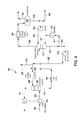
- FIG. 1 depicts an integrated system for low emission power generation and enhanced CO 2 recovery, according to one or more embodiments of the present disclosure.
- FIG. 2 depicts another integrated system for low emission power generation and enhanced CO 2 recovery, according to one or more embodiments of the present disclosure.
- FIG. 3 depicts another integrated system for low emission power generation and enhanced oil recovery, according to one or more embodiments of the present disclosure.
- FIG. 4 depicts an illustrative CO 2 capture system, according to one or more embodiments of the present disclosure.
- FIG. 5 depicts another illustrative CO 2 capture system, according to one or more embodiments of the present disclosure.
- FIG. 6 depicts another illustrative CO 2 capture system, according to one or more embodiments of the present disclosure.
- FIG. 7 depicts another illustrative CO 2 capture system, according to one or more embodiments of the present disclosure.
- FIG. 8 depicts an integrated system for low emission power generation and nitrogen expansion for enhanced oil recovery, according to one or more embodiments of the present disclosure.
- natural gas refers to a multi-component gas obtained from a crude oil well (associated gas) or from a subterranean gas-bearing formation (non-associated gas).
- the composition and pressure of natural gas can vary significantly.
- a typical natural gas stream contains methane (CH 4 ) as a major component, i.e. greater than 50 mol % of the natural gas stream is methane.
- the natural gas stream can also contain ethane (C 2 H 6 ), higher molecular weight hydrocarbons (e.g., C 3 -C 20 hydrocarbons), one or more acid gases (e.g., hydrogen sulfide, carbon dioxide), or any combination thereof.
- the natural gas can also contain minor amounts of contaminants such as water, nitrogen, iron sulfide, wax, crude oil, or any combination thereof.
- the term “stoichiometric combustion” refers to a combustion reaction having a volume of reactants comprising a fuel and an oxidizer and a volume of products formed by combusting the reactants where the entire volume of the reactants is used to form the products.
- the term “substantially stoichiometric combustion” refers to a combustion reaction having a molar ratio of combustion fuel to oxygen ranging from about plus or minus 10% of the oxygen required for a stoichiometric ratio or more preferably from about plus or minus 5% of the oxygen required for the stoichiometric ratio.
- the stoichiometric ratio of fuel to oxygen for methane is 1:2 (CH 4 +20> 2 >CO 2 +2H 2 O).
- Propane will have a stoichiometric ratio of fuel to oxygen of 1:5.
- Another way of measuring substantially stoichiometric combustion is as a ratio of oxygen supplied to oxygen required for stoichiometric combustion, such as from about 0.9:1 to about 1.1:1, or more preferably from about 0.95:1 to about 1.05:1.
- Embodiments of the presently disclosed systems and processes may be used to produce ultra low emission electric power and CO 2 for enhanced oil recovery (EOR) or sequestration applications.
- a mixture of air and fuel can be stoichiometrically or substantially stoichiometrically combusted and mixed with a stream of recycled exhaust gas.
- the stream of recycled exhaust gas generally including products of combustion such as CO 2 , can be used as a diluent to control or otherwise moderate the temperature of the stoichiometric combustion and exhaust gas entering the succeeding expander.
- a relatively high content CO 2 stream can be produced. While a portion of the recycled exhaust gas can be utilized for temperature moderation in the closed Brayton cycle, a remaining purge stream can be used for EOR applications and electric power can be produced with little or no SO X , NO X , or CO 2 being emitted to the atmosphere.
- the stoichiometric or substantially stoichiometric combustion of the fuel combined with a boost in the pressure or other increase in the mass flow rate of the exhaust gas prior to being compressed for recirculation can make the CO 2 partial pressure much higher than in conventional gas turbine exhaust.
- carbon capture in a CO 2 separator can be undertaken using less energy-intensive solvents, such as potassium carbonate (K 2 CO 3 ) or sodium carbonate (Na 2 CO 3 ).
- K 2 CO 3 potassium carbonate
- Na 2 CO 3 sodium carbonate
- oxygen (O 2 ), SO X , and NO X in the exhaust gas make the use of amine solvents (e.g., MEA, DEA, MDEA, and related solvents) difficult, even with the higher pressure and increased CO 2 content, since amine solvents can degrade in their presence.
- amine solvents e.g., MEA, DEA, MDEA, and related solvents
- the potassium or sodium carbonate solvents tolerate the minimal oxygen content of the present disclosure without degradation. Moreover, potassium carbonate easily absorbs SO X or NO X , converting it to simple fertilizers such as potassium sulfite (K 2 SO 3 ) and potassium nitrate (KNO 3 ). These fertilizers can be easily discharged in an environmentally harmless manner.
- FIG. 1 depicts a schematic of an illustrative integrated system 100 for power generation and CO 2 recovery using a combined-cycle arrangement, according to one or more embodiments.
- the power generation system 100 can include a gas turbine system 102 characterized as a power-producing, closed Brayton cycle.
- the gas turbine system 102 can have a first or main compressor 104 coupled to an expander 106 via a shaft 108 .
- the shaft 108 can be any mechanical, electrical, or other power coupling, thereby allowing a portion of the mechanical energy generated by the expander 106 to drive the main compressor 104 .
- the gas turbine system 102 can be a standard gas turbine, where the main compressor 104 and expander 106 form the compressor and expander ends, respectively. In other embodiments, however, the main compressor 104 and expander 106 can be individualized components in the system 102 .
- the gas turbine system 102 can also include a combustion chamber 110 configured to combust a fuel in line 112 mixed with a compressed oxidant in line 114 .
- the fuel in line 112 can include any suitable hydrocarbon gas or liquid, such as natural gas, methane, ethane, naphtha, butane, propane, syngas, diesel, kerosene, aviation fuel, coal derived fuel, bio-fuel, oxygenated hydrocarbon feedstock, or combinations thereof.
- the compressed oxidant in line 114 can be derived from a second or inlet compressor 118 fluidly coupled to the combustion chamber 110 and adapted to compress a feed oxidant 120 .
- the feed oxidant 120 can include any suitable gas containing oxygen, such as air, oxygen-rich air, oxygen-depleted air, pure oxygen, or combinations thereof.
- the combustion chamber 110 can also receive a compressed recycle stream 144 , including an exhaust gas primarily having CO 2 and nitrogen components.
- the compressed recycle stream 144 can be derived from the main compressor 104 and adapted to help facilitate the stoichiometric or substantially stoichiometric combustion of the compressed oxidant in line 114 and fuel in line 112 , and also increase the CO 2 concentration in the exhaust gas.
- An exhaust gas in line 116 can be generated as a product of combustion of the fuel in line 112 and the compressed oxidant in line 114 , in the presence of the compressed recycle stream 144 .
- the exhaust gas 116 is directed to the inlet of the expander 106 .
- the fuel in line 112 can be primarily natural gas, thereby generating an exhaust gas in line 116 including volumetric portions of vaporized water, CO 2 , nitrogen, nitrogen oxides (NOx), and sulfur oxides (SO X ).
- an exhaust gas in line 116 including volumetric portions of vaporized water, CO 2 , nitrogen, nitrogen oxides (NOx), and sulfur oxides (SO X ).
- a small portion of unburned fuel or other compounds may also be present in the exhaust gas in line 116 due to combustion equilibrium limitations.
- the exhaust gas in line 116 expands through the expander 106 it generates mechanical power to drive the main compressor 104 , an electrical generator, or other facilities, and also produces a gaseous exhaust in line 122 having a heightened CO 2 content resulting from the influx of the compressed recycle exhaust gas in line 144 .
- the power generation system 100 can also include an exhaust gas recirculation (EGR) system 124 .
- the EGR system 124 can include a heat recovery steam generator (HRSG) 126 , or similar device, fluidly coupled to a steam gas turbine 128 .
- HRSG heat recovery steam generator
- the combination of the HRSG 126 and the steam gas turbine 128 can be characterized as a closed Rankine cycle.
- the HRSG 126 and the steam gas turbine 128 can form part of a combined-cycle power generating plant, such as a natural gas combined-cycle (NGCC) plant.
- NGCC natural gas combined-cycle
- the gaseous exhaust in line 122 can be sent to the HRSG 126 in order to generate steam in line 130 and a cooled exhaust gas in line 132 .
- the steam in line 130 can be sent to the steam gas turbine 128 to generate additional electrical power.
- the cooled exhaust gas in line 132 can be sent to any variety of apparatus and/or facilities in a recycle loop back to the main compressor 104 .
- cooling units and/or booster compressors are shown and described in varying orders and configurations, each of which can be understood as being adapted to increase the mass flow rate of the cooled exhaust gas. By increasing the mass flow rate of the cooled exhaust gas entering the main compressor, a higher outlet pressure may be obtained from the main compressor.
- the recycle loop may comprise at least one cooling unit 134 configured to reduce the temperature of the cooled exhaust gas in line 132 and generate a cooled recycle gas stream 140 .
- the cooling unit 134 can be a direct contact cooler, trim cooler, a mechanical refrigeration unit, or combinations thereof.
- the cooling unit 134 can also be configured to remove a portion of condensed water via a water dropout stream 138 which can, in at least one embodiment, be routed to the HRSG 126 via line 141 to provide a water source for the generation of additional steam in line 130 .
- the cooled recycle gas stream 140 can be directed to a boost compressor 142 fluidly coupled to the cooling unit 134 . Cooling the cooled exhaust gas in line 132 in the cooling unit 134 can reduce the power required to compress the cooled recycle gas stream 140 in the boost compressor 142 .
- the boost compressor 142 can be configured to increase the pressure of the cooled recycle gas stream 140 before it is introduced into the main compressor 104 .
- the boost compressor 142 increases the overall density of the cooled recycle gas stream 140 , thereby directing an increased mass flow rate for the same volumetric flow to the main compressor 104 .
- the main compressor 104 is typically volume-flow limited, directing more mass flow through the main compressor 104 can result in a higher discharge pressure from the main compressor 104 , thereby translating into a higher pressure ratio across the expander 106 .
- a higher pressure ratio generated across the expander 106 can allow for higher inlet temperatures and, therefore, an increase in expander 106 power and efficiency. This can prove advantageous since the CO 2 -rich exhaust gas in line 116 generally maintains a higher specific heat capacity.
- the main compressor 104 can be configured to compress the cooled recycle gas stream 140 received from the boost compressor 142 to a pressure nominally above the combustion chamber 110 pressure, thereby generating the compressed recycle stream 144 .
- a purge stream 146 can be tapped from the compressed recycle stream 144 and subsequently treated in a CO 2 separator 148 to capture CO 2 at an elevated pressure via line 150 .
- the separated CO 2 in line 150 can be used for sales, used in another process requiring carbon dioxide, and/or compressed and injected into a terrestrial reservoir for enhanced oil recovery (EOR), sequestration, or another purpose.
- EOR enhanced oil recovery
- an exhaust gas in line 156 can be vented to the atmosphere or implemented into other downstream applications known in the art.
- the expanded nitrogen stream can be used in an evaporative cooling process configured to further reduce the temperature of the exhaust gas as generally described in the concurrently filed U.S. patent application entitled “Stoichiometric Combustion with Exhaust Gas Recirculation and Direct Contact Cooler,” the contents of which are hereby incorporated by reference to the extent not inconsistent with the present disclosure.
- the combination of the gas expander 152 , inlet compressor 118 , and CO 2 separator can be characterized as an open Brayton cycle, or the third power producing component of the system 100 .
- the gas expander 152 can be used to provide power to other applications, and not directly coupled to the stoichiometric compressor 118 .
- the expander 152 could be adapted to drive a smaller compressor (not shown) that demands less power.
- the expander 152 could be adapted to drive other equipment as appropriate.
- the gas expander 152 can be replaced with a downstream compressor 188 configured to compress the residual stream 151 and generate a compressed exhaust gas in line 190 .
- the compressed exhaust gas in line 190 can be suitable for injection into a reservoir for pressure maintenance applications.
- compressing the residual stream 151 may prove advantageous.
- the pressurized nitrogen gas in line 190 can instead be injected into the hydrocarbon wells and any residual methane gas can be sold or otherwise used as a fuel in related applications, such as providing fuel in line 112 .
- the EGR system 124 as described herein, especially with the addition of the boost compressor 142 , can be implemented to achieve a higher concentration of CO 2 in the exhaust gas of the power generation system 100 , thereby allowing for more effective CO 2 separation for subsequent sequestration, pressure maintenance, or EOR applications.
- embodiments disclosed herein can effectively increase the concentration of CO 2 in the exhaust gas stream to about 10 vol % or higher.
- the combustion chamber 110 can be adapted to stoichiometrically combust the incoming mixture of fuel in line 112 and compressed oxidant in line 114 .
- a portion of the exhaust gas derived from the compressed recycle stream 144 can be injected into the combustion chamber 110 as a diluent.
- the gaseous exhaust in line 122 can have less than about 3.0 vol % oxygen, or less than about 1.0 vol % oxygen, or less than about 0.1 vol % oxygen, or even less than about 0.001 vol % oxygen.
- the inlet compressor 118 can be configured as a stoichiometric compressor that provides compressed oxidant in line 114 at pressures ranging between about 280 psia and about 300 psia. Also contemplated herein, however, is aeroderivative gas turbine technology, which can produce and consume pressures of up to about 750 psia and more.
- the main compressor 104 can be configured to recycle and compress recycled exhaust gas into the compressed recycle stream 144 at a pressure nominally above or at the combustion chamber 110 pressure, and use a portion of that recycled exhaust gas as a diluent in the combustion chamber 110 . Because amounts of diluent needed in the combustion chamber 110 can depend on the purity of the oxidant used for stoichiometric combustion or the model of expander 106 , a ring of thermocouples and/or oxygen sensors (not shown) can be disposed associated with the combustion chamber and/or the expander. For example, thermocouples and/or oxygen sensors may be disposed on the outlet of the combustion chamber 110 , on the inlet to the expander 106 and/or on the outlet of the expander 106 .
- thermocouples and sensors can be adapted to determine the compositions and/or temperatures of one or more streams for use in determining the volume of exhaust gas required as diluent to cool the products of combustion to the required expander inlet temperature. Additionally or alternatively, the thermocouples and sensors may be adapted to determine the amount of oxidant to be injected into the combustion chamber 110 .
- the volumetric mass flow of compressed recycle gas in line 144 and/or compressed oxidant in line 114 can be manipulated or controlled to match the demand.
- the volumetric mass flow rates may be controlled through any suitable flow control systems, which may be in electrical communication with the thermocouples and/or oxygen sensors.
- a pressure drop of about 12-13 psia can be experienced across the combustion chamber 110 during stoichiometric combustion.
- Combustion of the fuel in line 112 and the compressed oxidant in line 114 can generate temperatures between about 2000° F. and about 3000° F. and pressures ranging from 250 psia to about 300 psia.
- a higher pressure ratio can be achieved across the expander 106 , thereby allowing for higher inlet temperatures and increased expander 106 power.
- the gaseous exhaust in line 122 exiting the expander 106 can have a pressure at or near ambient.
- the gaseous exhaust in line 122 can have a pressure of about 15.2 psia.
- the temperature of the gaseous exhaust in line 122 can range from about 1180° F. to about 1250° F. before passing through the HRSG 126 to generate steam in line 130 and a cooled exhaust gas in line 132 .
- the cooled exhaust gas in line 132 can have a temperature ranging from about 190° F. to about 200° F.
- the cooling unit 134 can reduce the temperature of the cooled exhaust gas in line 132 thereby generating the cooled recycle gas stream 140 having a temperature between about 32° F. and 120° F., depending primarily on wet bulb temperatures in specific locations and during specific seasons.
- the boost compressor 142 can be configured to elevate the pressure of the cooled recycle gas stream 140 to a pressure ranging from about 17.1 psia to about 21 psia. Additionally or alternatively, the mass flow rate of the cooled recycle gas stream may be increased through other means, such as cooling. As a result, the main compressor 104 receives and compresses a recycled exhaust gas with a higher density and increased mass flow, thereby allowing for a substantially higher discharge pressure while maintaining the same or similar pressure ratio. In at least one embodiment, the temperature of the compressed recycle stream 144 discharged from the main compressor 104 can be about 800° F., with a pressure of around 280 psia.
- the following table provides testing results and performance estimations based on combined-cycle gas turbines, with and without the added benefit of a boost compressor 142 , as described herein.
- embodiments including a boost compressor 142 can result in an increase in expander 106 power (i.e., “Gas Turbine Expander Power”) due to the increase in pressure ratios.
- the power demand for the main compressor 104 can increase, its increase is more than offset by the increase in power output of the expander 106 , thereby resulting in an overall thermodynamic performance efficiency improvement of around 1% lhv (lower heated value).
- the addition of the boost compressor 142 or cooling in the exhaust gas recirculation system can also increase the power output of the nitrogen expander 152 and the CO 2 purge pressure in the purge stream 146 line.
- An increase in purge pressure of the purge stream 146 can lead to improved solvent treating performance in the CO 2 separator 148 due to the higher CO 2 partial pressure.
- Such improvements can include, but are not limited to, a reduction in overall capital expenditures in the form of reduced equipment size for the solvent extraction process.
- FIG. 2 depicted is an alternative embodiment of the power generation system 100 of FIG. 1 , embodied and described as system 200 .
- FIG. 2 may be best understood with reference to FIG. 1 .
- the system 200 of FIG. 2 includes a gas turbine system 102 coupled to or otherwise supported by an exhaust gas recirculation (EGR) system 124 .
- the EGR system 124 in FIG. 2 can include an embodiment where the boost compressor 142 follows or may otherwise be fluidly coupled to the HRSG 126 .
- the cooled exhaust gas in line 132 can be compressed in the boost compressor 142 before being reduced in temperature in the cooling unit 134 .
- the cooling unit 134 can serve as an aftercooler adapted to remove the heat of compression generated by the boost compressor 142 .
- the water dropout stream 138 may or may not be routed to the HRSG 126 to generate additional steam in line 130 .
- the cooled recycle gas stream 140 can then be directed to the main compressor 104 where it is further compressed, as discussed above, thereby generating the compressed recycle stream 144 .
- cooling the cooled exhaust gas in line 132 in the cooling unit 134 after compression in the boost compressor 142 can reduce the amount of power required to compress the cooled recycle gas stream 140 to a predetermined pressure in the succeeding main compressor 104 .
- FIG. 3 depicts another embodiment of the low emission power generation system 100 of FIG. 1 , embodied as system 300 .
- FIG. 3 may be best understood with reference to FIGS. 1 and 2 .
- the system 300 includes a gas turbine system 102 supported by or otherwise coupled to an EGR system 124 .
- the EGR system 124 in FIG. 3 can include a first cooling unit 134 and a second cooling unit 136 , having the boost compressor 142 fluidly coupled therebetween.
- each cooling unit 134 , 136 can be a direct contact cooler, trim cooler, or the like, as known in the art.
- the cooled exhaust gas in line 132 discharged from the HRSG 126 can be sent to the first cooling unit 134 to produce a condensed water dropout stream 138 and a cooled recycle gas stream 140 .
- the cooled recycle gas stream 140 can be directed to the boost compressor 142 in order to boost the pressure of the cooled recycle gas stream 140 , and then direct it to the second cooling unit 136 .
- the second cooling unit 136 can serve as an aftercooler adapted to remove the heat of compression generated by the boost compressor 142 , and also remove additional condensed water via a water dropout stream 143 .
- each water dropout stream 138 , 143 may or may not be routed to the HRSG 126 to generate additional steam in line 130 .
- the cooled recycle gas stream 140 can then be introduced into the main compressor 104 to generate the compressed recycle stream 144 nominally above or at the combustion chamber 110 pressure.
- cooling the cooled exhaust gas in line 132 in the first cooling unit 134 can reduce the amount of power required to compress the cooled recycle gas stream 140 in the boost compressor 142 .
- further cooling exhaust in the second cooling unit 136 can reduce the amount of power required to compress the cooled recycle gas stream 140 to a predetermined pressure in the succeeding main compressor 104 .
- FIG. 4 depicted is an exemplary embodiment of a CO 2 separation system 400 that can employ potassium carbonate solvent technology as described herein.
- the CO 2 separation system 400 can be or form at least a portion of the CO 2 separator 148 , as generally described herein with reference to FIGS. 1-3 .
- the system 400 can be configured to receive the purge stream 146 tapped from the compressed recycle stream 144 ( FIGS. 1-3 ) at a temperature of around 800° F. and a pressures of around 270 psia to about 280 psia.
- the purge stream 146 containing primarily nitrogen, CO 2 , and excess combustion water, can be cooled in a heat exchanger 402 to a temperature ranging from about 250° F. to about 300° F., thereby generating a cooled purge stream in line 404 .
- the heat exchanger 402 can generate steam to be integrated with the steam stream 130 from the HRSG 126 ( FIGS. 1-3 ). Extracting CO 2 from the purge stream 146 in the CO 2 separation system 400 generates a nitrogen-rich residual stream 151 at or near the elevated pressure of the purge stream 146 and at a temperature of about 150° F.
- the heat exchanger 402 can be a cross-exchange heat exchanger fluidly coupled to the residual stream 151 and configured to extract the heat energy associated with cooling the purge stream 146 in order to re-heat the residual stream 151 .
- the residual stream 151 consisting primarily of a nitrogen vapor having a temperature of about 750° F. and a pressure of around 270-280 psia, can be subsequently expanded to generate mechanical power, as generally described above.
- the cooled purge stream in line 404 can be directed to an absorber column 406 where a solvent from line 408 is circulated, and the residual stream 151 is simultaneously discharged overhead for further downstream processing.
- the solvent is a water-based salt solution of potassium carbonate.
- the potassium carbonate solvent is quite temperature-tolerant. As a result, the cooling of the purge stream 146 can be minimized, as needed, and a higher temperature purge stream 146 can be allowed to enter the absorber column 406 without raising thermal degradation concerns. Accordingly, the degree of cooling of the purge stream 146 can be modified to match process heat requirements, rather than cooling to avoid thermal degradation.
- a rich, bicarbonate solvent can be discharged from the bottom of the absorber column 406 via line 410 and directed to a regeneration column 412 .
- a first or intermediate valve 414 disposed in the line 410 can be configured to flash the bicarbonate solvent to a lower, near-atmospheric pressure before introduction to the regeneration column 412 .
- the first valve 414 can be a hydraulic turbine configured to generate extra power.
- the regeneration column 412 can operate at temperatures exceeding the normal boiling point of water.
- the regeneration column 412 can operate at a temperature range from about 220° F., about 230° F., or about 240° F. to about 280° F., about 290° F., or about 300° F.
- the regeneration column 412 can operate at pressures ranging from about 0 psig to about 10 psig. In at least one embodiment, the regeneration column 412 can be configured to operate at a pressure of about 3 psig.
- the regeneration column 412 can be configured to use steam circulating therein to boil the bicarbonate solvent and reverse the reaction undertaken in the absorber column 406 , thereby yielding a regenerated, lean potassium carbonate solvent suitable for recirculation via line 416 below.
- an in-line pump 418 or the like, can drive at least a portion of the lean potassium carbonate solvent via line 420 back to the absorber column 406 .
- a portion of the lean potassium carbonate solvent can be removed as a heat stable salt (HSS) via line 423 .
- HSSs extracted via line 423 can include compound fertilizers such as, but not limited to, potassium sulfite and/or potassium nitrate.
- a stream of potassium hydroxide can be subsequently added via line 425 .
- the potassium hydroxide serves as a solvent makeup.
- the lean potassium carbonate solvent in line 420 can then be optionally directed through a first cooling unit 422 .
- the first cooling unit 422 can be, for example, an air cooler or radiator-type heat exchanger, configured to reduce the temperature of the solvent. If used, the first cooling unit 422 can be configured to reduce the temperature of the lean potassium carbonate solvent to temperatures ranging between about 230° F. and about 60° F. As can be appreciated, in at least one embodiment the HSSs can alternatively be removed as fertilizers subsequent to the first cooling unit 422 , as well as the addition of potassium hydroxide.
- the lean potassium carbonate solvent in line 416 can be directed to a reboiler 419 via line 417 .
- the reboiler 419 can be configured to increase the temperature of the lean potassium carbonate solvent in line 417 , and return a heated regenerated potassium carbonate solvent back to the regeneration column via line 421 .
- the reboiler 419 can be supplied with heat from the HRSG 126 ( FIGS. 1-3 ). In other embodiments, however, the reboiler 419 can be supplied with heat from the discharge of the steam gas turbine 128 ( FIGS. 1-3 ).
- the water included in the purge stream 146 can condense into the solvent solution in the absorber column 406 , and subsequently boil out in the regeneration column 412 . Consequently, the regeneration column 412 can further discharge CO 2 vapor and any residual water via overhead line 424 .
- the CO 2 vapor and residual water can be directed through a second cooling unit 426 , such as an air cooler or radiator-type heat exchanger, before being introduced into a condenser 428 .
- the condenser 428 can be configured to separate the residual water from any recovered CO 2 and direct the separated water into line 430 below while feeding the recovered CO 2 into line 150 overhead.
- line 150 can be the same line 150 as described above with reference to FIGS. 1-3 .
- the separated CO 2 in line 150 can be subsequently compressed for applications such as CO 2 sequestration, enhanced oil recovery, CO 2 sales, carbon capture, and/or combinations thereof.
- At least a portion of the separated water in line 430 can be recirculated back into the regeneration column 412 via line 434 using a pump 432 to allow the balance of water in the system to be maintained constant.
- Water is constantly introduced into the solvent via stream 404 , and subsequently removed via lines 436 , 150 , and 151 .
- the water recirculated in line 434 can allow water to be returned so that steam raised in line 421 can be controlled independently of this water balance.
- this recirculated water can be used as feedwater for the generation of steam in the regeneration column 412 or to raise low pressure steam from feed cooling.
- a portion of the residual water in line 430 can be disposed of as fresh process water via line 436 .
- the water in line 436 can be used for irrigation water, treated to be used for boiler feed water, and/or other process water.
- FIG. 5 depicted is another illustrative embodiment of a CO 2 separation system 500 , similar in some respects to the system 400 of FIG. 4 . As such, the entire system 500 will not be described in detail but may be best understood with reference to FIG. 4 . Whereas the system 400 of FIG. 4 could be characterized as a single-stage potassium carbonate process, the system 500 of FIG. 5 can be characterized, in at least one embodiment, as a two-stage potassium carbonate process. As depicted, the CO 2 separation system 500 can include a “semi-lean” solvent recirculation loop, wherein a portion of the solvent can be withdrawn from the regeneration column 412 via line 502 prior to complete regeneration.
- a “semi-lean” solvent recirculation loop wherein a portion of the solvent can be withdrawn from the regeneration column 412 via line 502 prior to complete regeneration.
- the portion of the solvent withdrawn via line 502 can be about 50% or more of the total solvent volume circulating through the regeneration column 412 .
- the balance of the solvent solution remaining in the regeneration column 412 can be fully regenerated, as described above, and discharged via line 416 therebelow.
- a pump 504 disposed within line 502 can direct the semi-lean solvent solution to the absorber column 406 .
- the semi-lean solvent solution can be fed low 506 into the absorber column 406 . Being only partially regenerated, the semi-lean solvent in line 502 is not able to absorb CO 2 from the lower concentration gases higher in the absorber column 406 . Instead, it can be fed into the absorber column 406 where it can absorb the maximum amount of CO 2 , and not dilute the fully lean solvent entering the absorber column 406 via line 408 .
- This variation in the system 500 can require a higher solvent circulation flowrate than the system 400 of FIG. 4 , but can demand less external heat energy to remove the CO 2 .
- the system 500 can require less reboiler 419 heat duty than is contained in the purge stream 146 .
- the heat of the incoming purge stream 146 may be able to supply all the reboiler 419 heat requirements. Consequently, if the residual stream 151 is injected for EOR, the system 500 can be thermally self-sufficient and require no make-up heat from the power turbine HRSG 126 .
- the rich, bicarbonate solvent can be discharged from the bottom of the absorber column 406 via line 410 and reduced in pressure using a first valve 602 before being introduced into a separator 604 .
- the first valve 602 can be configured to reduce the pressure of the bicarbonate solvent from the purge stream 146 pressure (e.g., between about 270-280 psia) to an intermediate pressure level.
- the intermediate pressure level can range from about 20 psia to about 50 psia.
- the separator 604 can be configured to receive the reduced-pressure solution and remove at least a portion of CO 2 via overhead line 606 .
- the removed CO 2 in line 606 can be cooled in a cooling unit 608 , and subsequently fed into a downstream compression system 607 .
- the cooling unit 608 can be a direct contact cooler, trim cooler, a mechanical refrigeration unit, or combinations thereof. Since the removed portion of CO 2 in line 606 is at an elevated pressure, albeit an intermediate pressure between the pressure of the purge stream 146 and atmospheric, it can be injected into an intermediate stage of the downstream compression system 607 , thereby reducing the required compression load on the compression system 607 .
- the balance of the CO 2 and bicarbonate solvent remaining in the separator 604 can be discharged from the separator 604 via line 610 below and flashed to a lower, near-atmospheric pressure in stream 611 using a second valve 612 before being directed into the regeneration column 412 .
- complete solvent regeneration can then take place as described above with reference to either system 400 or system 500 as depicted in FIG. 4 or 5 , respectively.
- a separated portion of CO 2 can be extracted from the condenser 428 via line 150 at or near atmospheric pressure and directed to a first compression stage of the downstream compression system 607 .
- the downstream compression system 607 can receive at least two feed streams substantially including captured CO 2 ; one feed stream having high pressure CO 2 in line 606 that is injected into an intermediate compression stage, and a second feed stream having low pressure CO 2 in line 150 and injected at the first compression stage.
- such an arrangement can reduce the power demand for CO 2 compression in preparation for EOR or sequestration at virtually no increase in regenerator column 412 thermal load.
- At least one benefit derived from the system 600 is the ability to produce a pure or nearly pure CO 2 stream from the regeneration column 412 .
- the contaminants present in the CO 2 stream in line 410 can include water and some volatile gases (e.g., N 2 , CO, Ar, etc.) dissolved into the circulating solvent.
- the system 600 can be adapted to remove essentially all of these volatile gases, leaving the regeneration column 412 overhead stream 424 with only high purity CO 2 and water.
- the CO 2 concentration in the overhead line 424 can be around 2 ⁇ 3 of the total CO 2 flow in the system 600 .
- a portion of the CO 2 in line 150 can be directed into a purge line 614 and captured for non-EOR uses, such as chemical feedstock, food production, etc.
- FIG. 7 depicted is another exemplary embodiment of a CO 2 separation system 700 .
- the system 700 is similar in some respects to the systems 400 and 500 described above, the entire system 700 will not be described in detail but may be best understood with reference to FIGS. 4 and 5 .
- the system 700 can prove particularly advantageous in embodiments where the residual stream 151 and captured CO 2 in line 150 are to be reinjected in EOR applications.
- the system 700 can be configured to allow superior integration of the cooling of purge stream 146 in conjunction with the process heat requirements in the regeneration column 412 and reboiler 419 .
- the heat exchanger 402 is not necessarily cross-exchanged with the residual stream 151 , but instead its heat energy can be available for other uses.
- the heat exchanger 402 can be configured to receive at least a portion of the recovered combustion water, or wastewater from line 436 to generate a low pressure steam in line 702 .
- the resulting steam in line 702 can have a pressure of about 50 psig or higher and can be split into lines 702 a and 702 b and used as motive power gas for one or more eductors 704 a and 704 b . While two lines 702 a and 702 b and two eductors 704 a and 704 b are shown in FIG. 7 , it will be appreciated that there can be more or less, without departing from the scope of the disclosure.
- the eductors 704 a and 704 b can be configured as steam ejectors adapted to reduce the pressure on the lean potassium carbonate solvent discharged into line 416 from the regeneration column 412 .
- the lean solvent in line 416 can be directed into one or more mixing chambers 706 a and 706 b arranged in series and fluidly coupled to the eductors 704 a and 704 b , respectively.
- the first mixing chamber 706 a can feed the second mixing chamber 706 b for further processing.
- the mixing chambers 706 a and 706 b may be arranged in parallel, without departing from the scope of the disclosure.
- the eductors 704 a and 704 b can be adapted to accelerate the steam in line 702 to create a low-pressure zone at or near vacuum conditions configured to flash-boil the lean solvent in the mixing chambers 706 a and 706 b .
- Boiling the lean solvent can release additional water and CO 2 not recovered via overhead line 424 and draw the resulting gaseous effluent into lines 708 a and 708 b .
- the resulting effluent in lines 708 a and 708 b can be injected into the regeneration column 412 to remove and capture the excess CO 2 via overhead line 424 .
- the effluent can also serve as stripping steam, thereby supplementing or entirely replacing at least some of the regenerative boiling heat duty generally supplied by the reboiler 419 . Accordingly, the system 700 can allow some of the heat held in the lean solvent to drive the vapor flow in the mixing chambers 706 a and 706 b , thereby reducing the net heat required for solvent regeneration and the overall size of the reboiler 419 .
- Flash-boiling the additional water and CO 2 in the mixing chambers 706 a and 706 b can also simultaneously cool the remaining lean solvent by reducing its pressure from about 3 psig to about 10 psig vacuum.
- the temperature of the lean solvent can be reduced from about 240° F., about 230° F., or about 220° F. to about 210° F., about 200° F., or about 190° F.
- the cooled lean solvent can then be discharged from the mixing chamber 706 b via line 710 and then directed to the in-line pump 418 which, as described above, can drive the solvent via line 420 back to the absorber column 406 . Since the temperature of the lean solvent can be cooled in the mixing chambers 706 a and 706 b , the size of the cooling unit 422 can be reduced.
- the low pressure steam provided in lines 702 a and 702 b to eductors 704 a and 704 b , respectively, is injected into the regeneration column 412 , it can result in the consumption of at least a portion of the feedwater derived from the separated water in line 434 . Accordingly, any additional water can be recovered from the regeneration column 412 via the overhead line 424 as additional wastewater. As a result, excess water can be continually building up in the system 700 and may be extracted via the wastewater line 436 . As can be appreciated, the water reflux rate can be varied to maintain the solvent water balance, or the potassium carbonate solution strength.
Abstract
Methods and systems for CO2 separation for low emission power generation in combined-cycle power plants are provided. One system includes a gas turbine system that stoichiometrically combusts a fuel and an oxidant in the presence of a compressed recycle stream to provide mechanical power and a gaseous exhaust. The compressed recycle stream acts as a diluent to moderate the temperature of the combustion process. A boost compressor can boost the pressure of the gaseous exhaust before being compressed into the compressed recycle stream. A purge stream is tapped off from the compressed recycle stream and directed to a CO2 separator configured to absorb CO2 from the purge stream using a potassium carbonate solvent.
Description
This application is the National Stage entry under 35 U.S.C. 371 of PCT/US2011/039830, that published as WO 2012/003080 and was filed on 9 Jun. 2011 which claims the benefit of U.S. Provisional Application No. 61/361,180, filed on 2 Jul. 2010, each of which is incorporated by reference, in its entirety, for all purposes.
This application contains subject matter related to PCT/US2011/042870, that published as WO 2012/003489 and was filed on 1 Jul. 2011; PCT/US2011/039824, that published as WO 2012/003076 and was filed on 9 Jun. 2011; PCT/US2011/039826, that published as WO 2012/003077 and was filed on 9 Jun. 2011; PCT/US2011/039828, that published as WO 2012/003078 and was filed on 9 Jun. 2011; and PCT/US2011/039829, that published as WO 2012/003079 and was filed on 9 Jun. 2011
Embodiments of the disclosure relate to low emission power generation in combined-cycle power systems.
This section is intended to introduce various aspects of the art, which may be associated with exemplary embodiments of the present disclosure. This discussion is believed to assist in providing a framework to facilitate a better understanding of particular aspects of the present disclosure. Accordingly, it should be understood that this section should be read in this light, and not necessarily as admissions of prior art.
Many oil producing countries are experiencing strong domestic growth in power demand and have an interest in enhanced oil recovery (EOR) to improve oil recovery from their reservoirs. Two common EOR techniques include nitrogen (N2) injection for reservoir pressure maintenance and carbon dioxide (CO2) injection for miscible flooding for EOR. There is also a global concern regarding green house gas (GHG) emissions. This concern combined with the implementation of cap-and-trade policies in many countries make reducing CO2 emissions a priority for these and other countries, as well as for the companies that operate hydrocarbon production systems therein.
Some approaches to lower CO2 emissions include fuel de-carbonization or post-combustion capture using solvents, such as amines. However, both of these solutions are expensive and reduce power generation efficiency, resulting in lower power production, increased fuel demand and increased cost of electricity to meet domestic power demand. In particular, the presence of oxygen, SOx, and NOx components makes the use of amine solvent absorption very problematic. Another approach is an oxyfuel gas turbine in a combined cycle (e.g., where exhaust heat from the gas turbine Brayton cycle is captured to make steam and produce additional power in a Rankin cycle). However, there are no commercially available gas turbines that can operate in such a cycle and the power required to produce high purity oxygen significantly reduces the overall efficiency of the process. Several studies have compared these processes and show some of the advantages of each approach. See, e.g. BOLLAND , OLAV , and UNDRUM , HENRIETTE , Removal of CO 2 from Gas Turbine Power Plants: Evaluation of pre- and post-combustion methods, SINTEF Group (1998).
Other approaches to lower CO2 emissions include stoichiometric exhaust gas recirculation, such as in natural gas combined cycles (NGCC). In a conventional NGCC system, only about 40% of the air intake volume is required to provide adequate stoichiometric combustion of the fuel, while the remaining 60% of the air volume serves to moderate the temperature and cool the exhaust gas so as to be suitable for introduction into the succeeding expander. The additional air volume also disadvantageously generates excess oxygen in the exhaust, which is difficult to remove. The typical NGCC produces low pressure exhaust gas which requires a fraction of the power produced to extract the CO2 for sequestration or EOR, thereby reducing the thermal efficiency of the NGCC. Further, the equipment for the CO2 extraction is large and expensive, and several stages of compression are required to take the ambient pressure gas to the pressure required for EOR or sequestration. Such limitations are typical of post-combustion carbon capture from low pressure exhaust gas associated with the combustion of other fossil fuels, such as coal.
The foregoing discussion of need in the art is intended to be representative rather than exhaustive. A technology addressing one or more such needs, or some other related shortcoming in the field, would benefit power generation in combined-cycle power systems.
The present disclosure provides systems and methods for generating power with an integrated CO2 separation system. Exemplary systems include a gas turbine system, an exhaust gas recirculation system, a heat exchanger, and a CO2 separator. The gas turbine system may have a combustion chamber configured to stoichiometrically combust a compressed oxidant and a fuel in the presence of a compressed recycle stream in order to generate a discharge stream, which is expanded in an expander, thereby generating a gaseous exhaust stream and at least partially driving a main compressor. The compressed recycle stream acts as a diluent configured to moderate the temperature of the discharge stream. The exhaust gas recirculation system may have at least one of a boost compressor and one or more cooling units configured to increase the mass flow rate of the gaseous exhaust stream to provide a cooled recycle gas to the main compressor. The main compressor compresses the cooled recycle gas and generates the compressed recycle stream, a portion of which is directed to the combustion chamber and a portion of which provides a purge stream. The CO2 separator may be fluidly coupled to the purge stream and may comprise an absorber column, a first valve, and a regeneration column. The absorber column may be configured to receive the purge stream and circulate a potassium carbonate solvent therein to absorb CO2 in the purge stream. The absorber column discharges a nitrogen-rich residual stream and a bicarbonate solvent solution. The first valve may be fluidly coupled to the absorber column and configured to flash the bicarbonate solvent solution to a near-atmospheric pressure. The regeneration column may be fluidly coupled to the first valve and configured to receive and boil the bicarbonate solvent solution to remove CO2 and water therefrom, thereby producing a regenerated potassium carbonate solvent to be recirculated back to the absorber column.
The present disclosure further provides related systems and methods adapted to remove CO2 from an exhaust gas recirculation stream.
The foregoing and other advantages of the present disclosure may become apparent upon reviewing the following detailed description and drawings of non-limiting examples of embodiments in which:
In the following detailed description section, the specific embodiments of the present disclosure are described in connection with preferred embodiments. However, to the extent that the following description is specific to a particular embodiment or a particular use of the present disclosure, this is intended to be for exemplary purposes only and simply provides a description of the exemplary embodiments. Accordingly, the disclosure is not limited to the specific embodiments described below, but rather, it includes all alternatives, modifications, and equivalents falling within the scope of the appended claims.
Various terms as used herein are defined below. To the extent a term used in a claim is not defined below, it should be given the broadest definition persons in the pertinent art have given that term as reflected in at least one printed publication or issued patent.
As used herein, the term “natural gas” refers to a multi-component gas obtained from a crude oil well (associated gas) or from a subterranean gas-bearing formation (non-associated gas). The composition and pressure of natural gas can vary significantly. A typical natural gas stream contains methane (CH4) as a major component, i.e. greater than 50 mol % of the natural gas stream is methane. The natural gas stream can also contain ethane (C2H6), higher molecular weight hydrocarbons (e.g., C3-C20 hydrocarbons), one or more acid gases (e.g., hydrogen sulfide, carbon dioxide), or any combination thereof. The natural gas can also contain minor amounts of contaminants such as water, nitrogen, iron sulfide, wax, crude oil, or any combination thereof.
As used herein, the term “stoichiometric combustion” refers to a combustion reaction having a volume of reactants comprising a fuel and an oxidizer and a volume of products formed by combusting the reactants where the entire volume of the reactants is used to form the products. As used herein, the term “substantially stoichiometric combustion” refers to a combustion reaction having a molar ratio of combustion fuel to oxygen ranging from about plus or minus 10% of the oxygen required for a stoichiometric ratio or more preferably from about plus or minus 5% of the oxygen required for the stoichiometric ratio. For example, the stoichiometric ratio of fuel to oxygen for methane is 1:2 (CH4+20>2>CO2+2H2O). Propane will have a stoichiometric ratio of fuel to oxygen of 1:5. Another way of measuring substantially stoichiometric combustion is as a ratio of oxygen supplied to oxygen required for stoichiometric combustion, such as from about 0.9:1 to about 1.1:1, or more preferably from about 0.95:1 to about 1.05:1.
Embodiments of the presently disclosed systems and processes may be used to produce ultra low emission electric power and CO2 for enhanced oil recovery (EOR) or sequestration applications. According to embodiments disclosed herein, a mixture of air and fuel can be stoichiometrically or substantially stoichiometrically combusted and mixed with a stream of recycled exhaust gas. The stream of recycled exhaust gas, generally including products of combustion such as CO2, can be used as a diluent to control or otherwise moderate the temperature of the stoichiometric combustion and exhaust gas entering the succeeding expander.
By cooling the exhaust gas and condensing the water out of the stream, a relatively high content CO2 stream can be produced. While a portion of the recycled exhaust gas can be utilized for temperature moderation in the closed Brayton cycle, a remaining purge stream can be used for EOR applications and electric power can be produced with little or no SOX, NOX, or CO2 being emitted to the atmosphere.
The stoichiometric or substantially stoichiometric combustion of the fuel combined with a boost in the pressure or other increase in the mass flow rate of the exhaust gas prior to being compressed for recirculation can make the CO2 partial pressure much higher than in conventional gas turbine exhaust. As a result, carbon capture in a CO2 separator can be undertaken using less energy-intensive solvents, such as potassium carbonate (K2CO3) or sodium carbonate (Na2CO3). The presence of oxygen (O2), SOX, and NOX in the exhaust gas make the use of amine solvents (e.g., MEA, DEA, MDEA, and related solvents) difficult, even with the higher pressure and increased CO2 content, since amine solvents can degrade in their presence. The potassium or sodium carbonate solvents tolerate the minimal oxygen content of the present disclosure without degradation. Moreover, potassium carbonate easily absorbs SOX or NOX, converting it to simple fertilizers such as potassium sulfite (K2SO3) and potassium nitrate (KNO3). These fertilizers can be easily discharged in an environmentally harmless manner.
Referring now to the figures, FIG. 1 depicts a schematic of an illustrative integrated system 100 for power generation and CO2 recovery using a combined-cycle arrangement, according to one or more embodiments. In at least one embodiment, the power generation system 100 can include a gas turbine system 102 characterized as a power-producing, closed Brayton cycle. The gas turbine system 102 can have a first or main compressor 104 coupled to an expander 106 via a shaft 108. The shaft 108 can be any mechanical, electrical, or other power coupling, thereby allowing a portion of the mechanical energy generated by the expander 106 to drive the main compressor 104. In at least one embodiment, the gas turbine system 102 can be a standard gas turbine, where the main compressor 104 and expander 106 form the compressor and expander ends, respectively. In other embodiments, however, the main compressor 104 and expander 106 can be individualized components in the system 102.
The gas turbine system 102 can also include a combustion chamber 110 configured to combust a fuel in line 112 mixed with a compressed oxidant in line 114. In one or more embodiments, the fuel in line 112 can include any suitable hydrocarbon gas or liquid, such as natural gas, methane, ethane, naphtha, butane, propane, syngas, diesel, kerosene, aviation fuel, coal derived fuel, bio-fuel, oxygenated hydrocarbon feedstock, or combinations thereof. The compressed oxidant in line 114 can be derived from a second or inlet compressor 118 fluidly coupled to the combustion chamber 110 and adapted to compress a feed oxidant 120. In one or more embodiments, the feed oxidant 120 can include any suitable gas containing oxygen, such as air, oxygen-rich air, oxygen-depleted air, pure oxygen, or combinations thereof.
As will be described in more detail below, the combustion chamber 110 can also receive a compressed recycle stream 144, including an exhaust gas primarily having CO2 and nitrogen components. The compressed recycle stream 144 can be derived from the main compressor 104 and adapted to help facilitate the stoichiometric or substantially stoichiometric combustion of the compressed oxidant in line 114 and fuel in line 112, and also increase the CO2 concentration in the exhaust gas. An exhaust gas in line 116 can be generated as a product of combustion of the fuel in line 112 and the compressed oxidant in line 114, in the presence of the compressed recycle stream 144. The exhaust gas 116 is directed to the inlet of the expander 106. In at least one embodiment, the fuel in line 112 can be primarily natural gas, thereby generating an exhaust gas in line 116 including volumetric portions of vaporized water, CO2, nitrogen, nitrogen oxides (NOx), and sulfur oxides (SOX). In some embodiments, a small portion of unburned fuel or other compounds may also be present in the exhaust gas in line 116 due to combustion equilibrium limitations. As the exhaust gas in line 116 expands through the expander 106 it generates mechanical power to drive the main compressor 104, an electrical generator, or other facilities, and also produces a gaseous exhaust in line 122 having a heightened CO2 content resulting from the influx of the compressed recycle exhaust gas in line 144.
The power generation system 100 can also include an exhaust gas recirculation (EGR) system 124. In one or more embodiments, the EGR system 124 can include a heat recovery steam generator (HRSG) 126, or similar device, fluidly coupled to a steam gas turbine 128. In at least one embodiment, the combination of the HRSG 126 and the steam gas turbine 128 can be characterized as a closed Rankine cycle. In combination with the gas turbine system 102, the HRSG 126 and the steam gas turbine 128 can form part of a combined-cycle power generating plant, such as a natural gas combined-cycle (NGCC) plant. The gaseous exhaust in line 122 can be sent to the HRSG 126 in order to generate steam in line 130 and a cooled exhaust gas in line 132. In one embodiment, the steam in line 130 can be sent to the steam gas turbine 128 to generate additional electrical power.
The cooled exhaust gas in line 132 can be sent to any variety of apparatus and/or facilities in a recycle loop back to the main compressor 104. In the illustrated implementations, cooling units and/or booster compressors are shown and described in varying orders and configurations, each of which can be understood as being adapted to increase the mass flow rate of the cooled exhaust gas. By increasing the mass flow rate of the cooled exhaust gas entering the main compressor, a higher outlet pressure may be obtained from the main compressor.
In some implementations, and as shown in FIG. 1 , the recycle loop may comprise at least one cooling unit 134 configured to reduce the temperature of the cooled exhaust gas in line 132 and generate a cooled recycle gas stream 140. In one or more embodiments, the cooling unit 134 can be a direct contact cooler, trim cooler, a mechanical refrigeration unit, or combinations thereof. The cooling unit 134 can also be configured to remove a portion of condensed water via a water dropout stream 138 which can, in at least one embodiment, be routed to the HRSG 126 via line 141 to provide a water source for the generation of additional steam in line 130. In one or more embodiments, the cooled recycle gas stream 140 can be directed to a boost compressor 142 fluidly coupled to the cooling unit 134. Cooling the cooled exhaust gas in line 132 in the cooling unit 134 can reduce the power required to compress the cooled recycle gas stream 140 in the boost compressor 142.
The boost compressor 142 can be configured to increase the pressure of the cooled recycle gas stream 140 before it is introduced into the main compressor 104. As opposed to a conventional fan or blower system, the boost compressor 142 increases the overall density of the cooled recycle gas stream 140, thereby directing an increased mass flow rate for the same volumetric flow to the main compressor 104. Because the main compressor 104 is typically volume-flow limited, directing more mass flow through the main compressor 104 can result in a higher discharge pressure from the main compressor 104, thereby translating into a higher pressure ratio across the expander 106. A higher pressure ratio generated across the expander 106 can allow for higher inlet temperatures and, therefore, an increase in expander 106 power and efficiency. This can prove advantageous since the CO2-rich exhaust gas in line 116 generally maintains a higher specific heat capacity.
The main compressor 104 can be configured to compress the cooled recycle gas stream 140 received from the boost compressor 142 to a pressure nominally above the combustion chamber 110 pressure, thereby generating the compressed recycle stream 144. In at least one embodiment, a purge stream 146 can be tapped from the compressed recycle stream 144 and subsequently treated in a CO2 separator 148 to capture CO2 at an elevated pressure via line 150. The separated CO2 in line 150 can be used for sales, used in another process requiring carbon dioxide, and/or compressed and injected into a terrestrial reservoir for enhanced oil recovery (EOR), sequestration, or another purpose.
A residual stream 151, essentially depleted of CO2 and consisting primarily of nitrogen, can be derived from the CO2 separator 148. In one or more embodiments, the residual stream 151 can be expanded in a gas expander 152, such as a power-producing nitrogen expander, fluidly coupled to the CO2 separator 148. As depicted in FIGS. 1-3 , the gas expander 152 can be optionally coupled to the inlet compressor 118 through a common shaft 154 or other mechanical, electrical, or other power coupling, thereby allowing a portion of the power generated by the gas expander 152 to drive the inlet compressor 118. After expansion in the gas expander 152, an exhaust gas in line 156, consisting primarily of nitrogen, can be vented to the atmosphere or implemented into other downstream applications known in the art. For example, the expanded nitrogen stream can be used in an evaporative cooling process configured to further reduce the temperature of the exhaust gas as generally described in the concurrently filed U.S. patent application entitled “Stoichiometric Combustion with Exhaust Gas Recirculation and Direct Contact Cooler,” the contents of which are hereby incorporated by reference to the extent not inconsistent with the present disclosure. In at least one embodiment, the combination of the gas expander 152, inlet compressor 118, and CO2 separator can be characterized as an open Brayton cycle, or the third power producing component of the system 100.
In other embodiments, however, the gas expander 152 can be used to provide power to other applications, and not directly coupled to the stoichiometric compressor 118. For example, there may be a substantial mismatch between the power generated by the expander 152 and the requirements of the compressor 118. In such cases, the expander 152 could be adapted to drive a smaller compressor (not shown) that demands less power. Additionally or alternatively, the expander 152 could be adapted to drive other equipment as appropriate. In yet other embodiments, as depicted in FIG. 8 , the gas expander 152 can be replaced with a downstream compressor 188 configured to compress the residual stream 151 and generate a compressed exhaust gas in line 190. In one or more embodiments, the compressed exhaust gas in line 190 can be suitable for injection into a reservoir for pressure maintenance applications. In applications where methane gas is typically reinjected into hydrocarbon wells to maintain well pressures, compressing the residual stream 151 may prove advantageous. For example, the pressurized nitrogen gas in line 190 can instead be injected into the hydrocarbon wells and any residual methane gas can be sold or otherwise used as a fuel in related applications, such as providing fuel in line 112.
The EGR system 124 as described herein, especially with the addition of the boost compressor 142, can be implemented to achieve a higher concentration of CO2 in the exhaust gas of the power generation system 100, thereby allowing for more effective CO2 separation for subsequent sequestration, pressure maintenance, or EOR applications. For instance, embodiments disclosed herein can effectively increase the concentration of CO2 in the exhaust gas stream to about 10 vol % or higher. To accomplish this, the combustion chamber 110 can be adapted to stoichiometrically combust the incoming mixture of fuel in line 112 and compressed oxidant in line 114. In order to moderate the temperature of the stoichiometric combustion to meet expander 106 inlet temperature and component cooling requirements, a portion of the exhaust gas derived from the compressed recycle stream 144 can be injected into the combustion chamber 110 as a diluent. Thus, embodiments of the disclosure can essentially eliminate any excess oxygen from the exhaust gas while simultaneously increasing its CO2 composition. As such, the gaseous exhaust in line 122 can have less than about 3.0 vol % oxygen, or less than about 1.0 vol % oxygen, or less than about 0.1 vol % oxygen, or even less than about 0.001 vol % oxygen.
The specifics of exemplary operation of the system 100 will now be discussed. As can be appreciated, specific temperatures and pressures achieved or experienced in the various components of any of the embodiments disclosed herein can change depending on, among other factors, the purity of the oxidant used and the specific makes and/or models of expanders, compressors, coolers, etc. Accordingly, it will be appreciated that the particular data described herein is for illustrative purposes only and should not be construed as the only interpretation thereof. In an embodiment, the inlet compressor 118 can be configured as a stoichiometric compressor that provides compressed oxidant in line 114 at pressures ranging between about 280 psia and about 300 psia. Also contemplated herein, however, is aeroderivative gas turbine technology, which can produce and consume pressures of up to about 750 psia and more.
The main compressor 104 can be configured to recycle and compress recycled exhaust gas into the compressed recycle stream 144 at a pressure nominally above or at the combustion chamber 110 pressure, and use a portion of that recycled exhaust gas as a diluent in the combustion chamber 110. Because amounts of diluent needed in the combustion chamber 110 can depend on the purity of the oxidant used for stoichiometric combustion or the model of expander 106, a ring of thermocouples and/or oxygen sensors (not shown) can be disposed associated with the combustion chamber and/or the expander. For example, thermocouples and/or oxygen sensors may be disposed on the outlet of the combustion chamber 110, on the inlet to the expander 106 and/or on the outlet of the expander 106. In operation, the thermocouples and sensors can be adapted to determine the compositions and/or temperatures of one or more streams for use in determining the volume of exhaust gas required as diluent to cool the products of combustion to the required expander inlet temperature. Additionally or alternatively, the thermocouples and sensors may be adapted to determine the amount of oxidant to be injected into the combustion chamber 110. Thus, in response to the heat requirements detected by the thermocouples and the oxygen levels detected by the oxygen sensors, the volumetric mass flow of compressed recycle gas in line 144 and/or compressed oxidant in line 114 can be manipulated or controlled to match the demand. The volumetric mass flow rates may be controlled through any suitable flow control systems, which may be in electrical communication with the thermocouples and/or oxygen sensors.
In at least one embodiment, a pressure drop of about 12-13 psia can be experienced across the combustion chamber 110 during stoichiometric combustion. Combustion of the fuel in line 112 and the compressed oxidant in line 114 can generate temperatures between about 2000° F. and about 3000° F. and pressures ranging from 250 psia to about 300 psia. Because of the increased mass flow and higher specific heat capacity of the CO2-rich exhaust gas derived from the compressed recycle stream 144, a higher pressure ratio can be achieved across the expander 106, thereby allowing for higher inlet temperatures and increased expander 106 power.
The gaseous exhaust in line 122 exiting the expander 106 can have a pressure at or near ambient. In at least one embodiment, the gaseous exhaust in line 122 can have a pressure of about 15.2 psia. The temperature of the gaseous exhaust in line 122 can range from about 1180° F. to about 1250° F. before passing through the HRSG 126 to generate steam in line 130 and a cooled exhaust gas in line 132. The cooled exhaust gas in line 132 can have a temperature ranging from about 190° F. to about 200° F. In one or more embodiments, the cooling unit 134 can reduce the temperature of the cooled exhaust gas in line 132 thereby generating the cooled recycle gas stream 140 having a temperature between about 32° F. and 120° F., depending primarily on wet bulb temperatures in specific locations and during specific seasons.
According to one or more embodiments, the boost compressor 142 can be configured to elevate the pressure of the cooled recycle gas stream 140 to a pressure ranging from about 17.1 psia to about 21 psia. Additionally or alternatively, the mass flow rate of the cooled recycle gas stream may be increased through other means, such as cooling. As a result, the main compressor 104 receives and compresses a recycled exhaust gas with a higher density and increased mass flow, thereby allowing for a substantially higher discharge pressure while maintaining the same or similar pressure ratio. In at least one embodiment, the temperature of the compressed recycle stream 144 discharged from the main compressor 104 can be about 800° F., with a pressure of around 280 psia.
The following table provides testing results and performance estimations based on combined-cycle gas turbines, with and without the added benefit of a boost compressor 142, as described herein.
| TABLE 1 |
| Triple-Cycle Performance Comparison |
| Recirc. Cycle | Recirc. Cycle w/ | |
| w/o Boost | Boost | |
| Power (MW) | Compressor | Compressor |
| Gas Turbine Expander Power | 1055 | 1150 |
| Main Compressor | 538 | 542 |
| Fan or Boost Compressor | 13 | 27 |
| Inlet Compressor | 283 | 315 |
| Total Compression Power | 835 | 883 |
| Net Gas Turbine Power | 216 | 261 |
| Steam Turbine Net Power | 395 | 407 |
| Standard |
611 | 668 |
| Aux. Losses | 13 | 15 |
| |
156 | 181 |
| Combined Cycle Power | 598 | 653 |
| Efficiency | ||
| Fuel Rate (mBTU/hr) | 5947 | 6322 |
| Heat Rate (BTU/kWh) | 9949 | 9680 |
| Combined Cycle Eff. (% lhv) | 34.3 | 35.2 |
| CO2 Purge Pressure (psia) | 280 | 308 |
As should be apparent from Table 1, embodiments including a boost compressor 142 can result in an increase in expander 106 power (i.e., “Gas Turbine Expander Power”) due to the increase in pressure ratios. Although the power demand for the main compressor 104 can increase, its increase is more than offset by the increase in power output of the expander 106, thereby resulting in an overall thermodynamic performance efficiency improvement of around 1% lhv (lower heated value).
Moreover, the addition of the boost compressor 142 or cooling in the exhaust gas recirculation system can also increase the power output of the nitrogen expander 152 and the CO2 purge pressure in the purge stream 146 line. An increase in purge pressure of the purge stream 146 can lead to improved solvent treating performance in the CO2 separator 148 due to the higher CO2 partial pressure. Such improvements can include, but are not limited to, a reduction in overall capital expenditures in the form of reduced equipment size for the solvent extraction process.
Referring now to FIG. 2 , depicted is an alternative embodiment of the power generation system 100 of FIG. 1 , embodied and described as system 200. As such, FIG. 2 may be best understood with reference to FIG. 1 . Similar to the system 100 of FIG. 1 , the system 200 of FIG. 2 includes a gas turbine system 102 coupled to or otherwise supported by an exhaust gas recirculation (EGR) system 124. The EGR system 124 in FIG. 2 , however, can include an embodiment where the boost compressor 142 follows or may otherwise be fluidly coupled to the HRSG 126. As such, the cooled exhaust gas in line 132 can be compressed in the boost compressor 142 before being reduced in temperature in the cooling unit 134. Thus, the cooling unit 134 can serve as an aftercooler adapted to remove the heat of compression generated by the boost compressor 142. As with previously disclosed embodiments, the water dropout stream 138 may or may not be routed to the HRSG 126 to generate additional steam in line 130.
The cooled recycle gas stream 140 can then be directed to the main compressor 104 where it is further compressed, as discussed above, thereby generating the compressed recycle stream 144. As can be appreciated, cooling the cooled exhaust gas in line 132 in the cooling unit 134 after compression in the boost compressor 142 can reduce the amount of power required to compress the cooled recycle gas stream 140 to a predetermined pressure in the succeeding main compressor 104.
In one or more embodiments, the cooled exhaust gas in line 132 discharged from the HRSG 126 can be sent to the first cooling unit 134 to produce a condensed water dropout stream 138 and a cooled recycle gas stream 140. The cooled recycle gas stream 140 can be directed to the boost compressor 142 in order to boost the pressure of the cooled recycle gas stream 140, and then direct it to the second cooling unit 136. The second cooling unit 136 can serve as an aftercooler adapted to remove the heat of compression generated by the boost compressor 142, and also remove additional condensed water via a water dropout stream 143. In one or more embodiments, each water dropout stream 138, 143 may or may not be routed to the HRSG 126 to generate additional steam in line 130.
The cooled recycle gas stream 140 can then be introduced into the main compressor 104 to generate the compressed recycle stream 144 nominally above or at the combustion chamber 110 pressure. As can be appreciated, cooling the cooled exhaust gas in line 132 in the first cooling unit 134 can reduce the amount of power required to compress the cooled recycle gas stream 140 in the boost compressor 142. Moreover, further cooling exhaust in the second cooling unit 136 can reduce the amount of power required to compress the cooled recycle gas stream 140 to a predetermined pressure in the succeeding main compressor 104.
The combination of stoichiometric combustion in the combustion chamber 110 and water removal through the cooling units 134, 136, allows the CO2 content in the exhaust gas (e.g., streams 122, 132, 140, and/or 144) to accumulate to about 10 vol % or higher, which is higher than exhaust gases in conventional combined-cycle systems. These effects, plus the impact of higher mass flow rates resulting from the implementation and effect of the boost compressor 142 and/or cooling units, make the CO2 partial pressure much higher than conventional gas turbine exhaust. Consequently, this allows for carbon capture in the CO2 separator 148 using less energy-intensive solvents, such as potassium carbonate (K2CO3) solvent technology.
The presence of oxygen (O2), SOX, and NOX make the use of amine solvents (e.g., MEA, DEA, MDEA, and related solvents) difficult, even with the higher pressure and increased CO2 content, since these gases can cause amine degradation. Potassium carbonate, however, is non-reactive and immune to any effects of oxygen. Although the reaction undertaken in the combustion chamber 110 is intended to be stoichiometric, a fraction of oxygen may nonetheless be present in the purge stream 146 due to combustion equilibrium limitations. While the use of MEA solvents in this application would require significant solvent reclamation and complicated disposal, the use of potassium carbonate solvents eliminates oxygen-based solvent degradation.
Potassium carbonate easily absorbs SOX or NOX in the exhaust gas, converting these compounds to simple fertilizers, such as potassium sulfite (K2SO3) and potassium nitrate (KNO3). In particular, SO2, SO3, and NO2 all form fairly strong acids in water, much stronger than CO2. Thus, they will be preferentially absorbed in the solvent solution, but will become heat stable salts (HSS) and will not be removed by regeneration. On the other hand, NO and N2O have low solubility and are more difficult to absorb than NO2, and tend to occur at lower concentrations. As simple fertilizers, the potassium sulfite and potassium nitrate can be easily discharged in an environmentally harmless manner, so long as no other toxic compounds, such as corrosion inhibitors, activators, etc., are added to the solvent system. When the sulfate and nitrate compounds are removed, potassium hydroxide (KOH) can be added for solvent makeup. Since potassium hydroxide is a fairly inexpensive chemical, this can be accomplished rather economically.
Referring to FIG. 4 , depicted is an exemplary embodiment of a CO2 separation system 400 that can employ potassium carbonate solvent technology as described herein. The CO2 separation system 400 can be or form at least a portion of the CO2 separator 148, as generally described herein with reference to FIGS. 1-3 . In one or more embodiments, the system 400 can be configured to receive the purge stream 146 tapped from the compressed recycle stream 144 (FIGS. 1-3 ) at a temperature of around 800° F. and a pressures of around 270 psia to about 280 psia.
The purge stream 146, containing primarily nitrogen, CO2, and excess combustion water, can be cooled in a heat exchanger 402 to a temperature ranging from about 250° F. to about 300° F., thereby generating a cooled purge stream in line 404. In an embodiment, the heat exchanger 402 can generate steam to be integrated with the steam stream 130 from the HRSG 126 (FIGS. 1-3 ). Extracting CO2 from the purge stream 146 in the CO2 separation system 400 generates a nitrogen-rich residual stream 151 at or near the elevated pressure of the purge stream 146 and at a temperature of about 150° F. In at least one embodiment, the heat exchanger 402 can be a cross-exchange heat exchanger fluidly coupled to the residual stream 151 and configured to extract the heat energy associated with cooling the purge stream 146 in order to re-heat the residual stream 151. Once reheated, the residual stream 151, consisting primarily of a nitrogen vapor having a temperature of about 750° F. and a pressure of around 270-280 psia, can be subsequently expanded to generate mechanical power, as generally described above.
The cooled purge stream in line 404 can be directed to an absorber column 406 where a solvent from line 408 is circulated, and the residual stream 151 is simultaneously discharged overhead for further downstream processing. In one embodiment, the solvent is a water-based salt solution of potassium carbonate. When compared to competing solvents, such as MEA, the potassium carbonate solvent is quite temperature-tolerant. As a result, the cooling of the purge stream 146 can be minimized, as needed, and a higher temperature purge stream 146 can be allowed to enter the absorber column 406 without raising thermal degradation concerns. Accordingly, the degree of cooling of the purge stream 146 can be modified to match process heat requirements, rather than cooling to avoid thermal degradation.
As CO2 is absorbed by the potassium carbonate in the absorber column 406, it reacts with water to form carbonic acid (H2CO3), and then bicarbonate (HCO3 −). The acidic part of the carbonic acid (H+) can react with the carbonate ion (CO3 −2) to form an additional bicarbonate ion. Thus, the overall reaction can be as follows:
CO2+H2O+K2CO3 2KHCO3
CO2+H2O+K2CO3
As a result, a rich, bicarbonate solvent can be discharged from the bottom of the absorber column 406 via line 410 and directed to a regeneration column 412. In one embodiment, a first or intermediate valve 414 disposed in the line 410 can be configured to flash the bicarbonate solvent to a lower, near-atmospheric pressure before introduction to the regeneration column 412. In at least one embodiment, the first valve 414 can be a hydraulic turbine configured to generate extra power.
In at least one embodiment, the regeneration column 412 can operate at temperatures exceeding the normal boiling point of water. For example, the regeneration column 412 can operate at a temperature range from about 220° F., about 230° F., or about 240° F. to about 280° F., about 290° F., or about 300° F. The regeneration column 412 can operate at pressures ranging from about 0 psig to about 10 psig. In at least one embodiment, the regeneration column 412 can be configured to operate at a pressure of about 3 psig. The regeneration column 412 can be configured to use steam circulating therein to boil the bicarbonate solvent and reverse the reaction undertaken in the absorber column 406, thereby yielding a regenerated, lean potassium carbonate solvent suitable for recirculation via line 416 below. In at least one embodiment, an in-line pump 418, or the like, can drive at least a portion of the lean potassium carbonate solvent via line 420 back to the absorber column 406.
En route to the absorber column 406, a portion of the lean potassium carbonate solvent can be removed as a heat stable salt (HSS) via line 423. As described above, illustrative HSSs extracted via line 423 can include compound fertilizers such as, but not limited to, potassium sulfite and/or potassium nitrate. In order to make up for the loss of potassium carbonate content removed via line 423, and to maintain overall solution strength, a stream of potassium hydroxide can be subsequently added via line 425. In one or more embodiments, the potassium hydroxide serves as a solvent makeup. The lean potassium carbonate solvent in line 420 can then be optionally directed through a first cooling unit 422. In one or more embodiments, the first cooling unit 422 can be, for example, an air cooler or radiator-type heat exchanger, configured to reduce the temperature of the solvent. If used, the first cooling unit 422 can be configured to reduce the temperature of the lean potassium carbonate solvent to temperatures ranging between about 230° F. and about 60° F. As can be appreciated, in at least one embodiment the HSSs can alternatively be removed as fertilizers subsequent to the first cooling unit 422, as well as the addition of potassium hydroxide.
In order to generate the steam circulating in the regeneration column 412 and maintain the required heat of regeneration, at least a portion of the lean potassium carbonate solvent in line 416 can be directed to a reboiler 419 via line 417. The reboiler 419 can be configured to increase the temperature of the lean potassium carbonate solvent in line 417, and return a heated regenerated potassium carbonate solvent back to the regeneration column via line 421. In at least one embodiment, the reboiler 419 can be supplied with heat from the HRSG 126 (FIGS. 1-3 ). In other embodiments, however, the reboiler 419 can be supplied with heat from the discharge of the steam gas turbine 128 (FIGS. 1-3 ).
The water included in the purge stream 146 can condense into the solvent solution in the absorber column 406, and subsequently boil out in the regeneration column 412. Consequently, the regeneration column 412 can further discharge CO2 vapor and any residual water via overhead line 424. In at least one embodiment, the CO2 vapor and residual water can be directed through a second cooling unit 426, such as an air cooler or radiator-type heat exchanger, before being introduced into a condenser 428. The condenser 428 can be configured to separate the residual water from any recovered CO2 and direct the separated water into line 430 below while feeding the recovered CO2 into line 150 overhead. As can be appreciated, line 150 can be the same line 150 as described above with reference to FIGS. 1-3 . In at least one embodiment, the separated CO2 in line 150 can be subsequently compressed for applications such as CO2 sequestration, enhanced oil recovery, CO2 sales, carbon capture, and/or combinations thereof.
In one embodiment, at least a portion of the separated water in line 430 can be recirculated back into the regeneration column 412 via line 434 using a pump 432 to allow the balance of water in the system to be maintained constant. Water is constantly introduced into the solvent via stream 404, and subsequently removed via lines 436, 150, and 151. In order to maintain solvent conditions and strength, the water must remain in balance within the system 400. Accordingly, the water recirculated in line 434 can allow water to be returned so that steam raised in line 421 can be controlled independently of this water balance. In other words, this recirculated water can be used as feedwater for the generation of steam in the regeneration column 412 or to raise low pressure steam from feed cooling. In other embodiments, a portion of the residual water in line 430 can be disposed of as fresh process water via line 436. For example, although containing a portion of dissolved CO2, the water in line 436 can be used for irrigation water, treated to be used for boiler feed water, and/or other process water.
Referring now to FIG. 5 , depicted is another illustrative embodiment of a CO2 separation system 500, similar in some respects to the system 400 of FIG. 4 . As such, the entire system 500 will not be described in detail but may be best understood with reference to FIG. 4 . Whereas the system 400 of FIG. 4 could be characterized as a single-stage potassium carbonate process, the system 500 of FIG. 5 can be characterized, in at least one embodiment, as a two-stage potassium carbonate process. As depicted, the CO2 separation system 500 can include a “semi-lean” solvent recirculation loop, wherein a portion of the solvent can be withdrawn from the regeneration column 412 via line 502 prior to complete regeneration. In at least one embodiment, the portion of the solvent withdrawn via line 502 can be about 50% or more of the total solvent volume circulating through the regeneration column 412. The balance of the solvent solution remaining in the regeneration column 412 can be fully regenerated, as described above, and discharged via line 416 therebelow.
A pump 504 disposed within line 502 can direct the semi-lean solvent solution to the absorber column 406. In one embodiment, the semi-lean solvent solution can be fed low 506 into the absorber column 406. Being only partially regenerated, the semi-lean solvent in line 502 is not able to absorb CO2 from the lower concentration gases higher in the absorber column 406. Instead, it can be fed into the absorber column 406 where it can absorb the maximum amount of CO2, and not dilute the fully lean solvent entering the absorber column 406 via line 408.
This variation in the system 500 can require a higher solvent circulation flowrate than the system 400 of FIG. 4 , but can demand less external heat energy to remove the CO2. With this improved thermal efficiency, the system 500 can require less reboiler 419 heat duty than is contained in the purge stream 146. In other words, the heat of the incoming purge stream 146 may be able to supply all the reboiler 419 heat requirements. Consequently, if the residual stream 151 is injected for EOR, the system 500 can be thermally self-sufficient and require no make-up heat from the power turbine HRSG 126.
Referring now to FIG. 6 , depicted is another exemplary embodiment of a CO2 separation system 600, similar in some respects to the systems 400, 500 of FIGS. 4 and 5 , respectively. As such, the entire system 600 will not be described in detail but may be best understood with reference to FIGS. 4 and 5 . As depicted, the rich, bicarbonate solvent can be discharged from the bottom of the absorber column 406 via line 410 and reduced in pressure using a first valve 602 before being introduced into a separator 604. In one embodiment, the first valve 602 can be configured to reduce the pressure of the bicarbonate solvent from the purge stream 146 pressure (e.g., between about 270-280 psia) to an intermediate pressure level. In one or more embodiments, the intermediate pressure level can range from about 20 psia to about 50 psia.
The separator 604 can be configured to receive the reduced-pressure solution and remove at least a portion of CO2 via overhead line 606. In one or more embodiments, the removed CO2 in line 606 can be cooled in a cooling unit 608, and subsequently fed into a downstream compression system 607. In one or more embodiments, the cooling unit 608 can be a direct contact cooler, trim cooler, a mechanical refrigeration unit, or combinations thereof. Since the removed portion of CO2 in line 606 is at an elevated pressure, albeit an intermediate pressure between the pressure of the purge stream 146 and atmospheric, it can be injected into an intermediate stage of the downstream compression system 607, thereby reducing the required compression load on the compression system 607.
The balance of the CO2 and bicarbonate solvent remaining in the separator 604 can be discharged from the separator 604 via line 610 below and flashed to a lower, near-atmospheric pressure in stream 611 using a second valve 612 before being directed into the regeneration column 412. In several embodiments of the system 600, complete solvent regeneration can then take place as described above with reference to either system 400 or system 500 as depicted in FIG. 4 or 5 , respectively. For instance, as described above a separated portion of CO2 can be extracted from the condenser 428 via line 150 at or near atmospheric pressure and directed to a first compression stage of the downstream compression system 607. Consequently, the downstream compression system 607 can receive at least two feed streams substantially including captured CO2; one feed stream having high pressure CO2 in line 606 that is injected into an intermediate compression stage, and a second feed stream having low pressure CO2 in line 150 and injected at the first compression stage. As can be appreciated, such an arrangement can reduce the power demand for CO2 compression in preparation for EOR or sequestration at virtually no increase in regenerator column 412 thermal load.
At least one benefit derived from the system 600 is the ability to produce a pure or nearly pure CO2 stream from the regeneration column 412. The contaminants present in the CO2 stream in line 410 can include water and some volatile gases (e.g., N2, CO, Ar, etc.) dissolved into the circulating solvent. The system 600 can be adapted to remove essentially all of these volatile gases, leaving the regeneration column 412 overhead stream 424 with only high purity CO2 and water. In one or more embodiments, the CO2 concentration in the overhead line 424 can be around ⅔ of the total CO2 flow in the system 600. Once separated from the water, a portion of the CO2 in line 150 can be directed into a purge line 614 and captured for non-EOR uses, such as chemical feedstock, food production, etc.
As can be appreciated, embodiments and features disclosed with reference to FIGS. 5-6 can be combined without departing from the disclosure. Accordingly, the following table and supplemental information provides illustrative process data for a combination of embodiments and/or features described above. The solvent stream and gas stream reference numerals shown in the table can be referred to in FIGS. 5-6 .
| TABLE 2 |
| Process Data |
| |
| 408 | 506 | 410 | 611 | 434 | |
| Temperature - ° F. | 120 | 219.81 | 230.8 | 208.3 | 112 |
| Pressure - psia | 276.2 | 277.2 | 276.2 | 17.7 | 16.7 |
| Flowrate (klb/hr) | 5,079 | 14,036 | 19,988 | 19,701 | 220 |
| Flowrate (USGPM) | 8,937 | 23,757 | 33,795 | 650,017 | 443 |
| Equiv. wt % K2CO3 in solution | 35.60% | 31.80% | 31.40% | 31.80% | 0.00% |
| % K2CO3 reacted to KHCO3 | 7.80% | 33.50% | 65.60% | 54.70% | N/A |
| Stream pH | 9.6 | 8.6 | 8.1 | 8.5 | 4.1 |
| |
| 146 | 151 | 606 | 424 | |
| Temperature - ° F. | 803.2 | 141.62 | 120 | 112 |
| Pressure - psia | 283.2 | 276.2 | 28 | 16.7 |
| Flowrate (lbmole/hr) | 158,729 | 132,137 | 5,497 | 10,969 |
| Flowrate (MMSCFD) | 1,446 | 1,203 | 50 | 100 |
| H2O Mole % | 7.97% | 0.98% | 6.14% | 8.17% |
| CO2 Mole % | 10.36% | 1.00% | 91.69% | 91.83% |
| Mole % Other (N2 + O2 + Ar + CO + H2) | 81.67% | 98.02% | 2.17% | 0.00% |
| Heat Required: | ||
| |
629 MBTU/hr | Total: |
| |
586 MBTU/hr (20 psig steam) | 586 MBTU/hr |
| Heat Rejected: | ||
| Cooling |
114 MBTU/hr | Total: |
| |
381 MBTU/hr | 1189 MBTU/ |
| Cooling Unit | ||
| 422 | 478 MBTU/hr | |
| CO2 Compressor Coolers (total) | 216 MBTU/hr | |
| Power Loads: | ||
| Gas Expander 152 (FIGS. 1-3) | 222,414 hp Produced | Total: |
| |
2,035 hp Consumed | 165,397 hp |
| Semi-Lean |
5,532 hp Consumed | |
| CO2 Compressor (total) | 49,450 hp Consumed | |
| Net Power Produced/Consumed | 165,397 hp Consumed |
Referring now to FIG. 7 , depicted is another exemplary embodiment of a CO2 separation system 700. Since the system 700 is similar in some respects to the systems 400 and 500 described above, the entire system 700 will not be described in detail but may be best understood with reference to FIGS. 4 and 5 . The system 700 can prove particularly advantageous in embodiments where the residual stream 151 and captured CO2 in line 150 are to be reinjected in EOR applications. As will be described below, the system 700 can be configured to allow superior integration of the cooling of purge stream 146 in conjunction with the process heat requirements in the regeneration column 412 and reboiler 419.
Since the residual stream 151 in the system 700 may be subsequently compressed for EOR, the heat exchanger 402 is not necessarily cross-exchanged with the residual stream 151, but instead its heat energy can be available for other uses. For example, in one or more embodiments, the heat exchanger 402 can be configured to receive at least a portion of the recovered combustion water, or wastewater from line 436 to generate a low pressure steam in line 702. The resulting steam in line 702 can have a pressure of about 50 psig or higher and can be split into lines 702 a and 702 b and used as motive power gas for one or more eductors 704 a and 704 b. While two lines 702 a and 702 b and two eductors 704 a and 704 b are shown in FIG. 7 , it will be appreciated that there can be more or less, without departing from the scope of the disclosure.
In one embodiment, the eductors 704 a and 704 b can be configured as steam ejectors adapted to reduce the pressure on the lean potassium carbonate solvent discharged into line 416 from the regeneration column 412. To accomplish this, the lean solvent in line 416 can be directed into one or more mixing chambers 706 a and 706 b arranged in series and fluidly coupled to the eductors 704 a and 704 b, respectively. In one embodiment, the first mixing chamber 706 a can feed the second mixing chamber 706 b for further processing. In other embodiments, however, the mixing chambers 706 a and 706 b may be arranged in parallel, without departing from the scope of the disclosure.
In operation, the eductors 704 a and 704 b can be adapted to accelerate the steam in line 702 to create a low-pressure zone at or near vacuum conditions configured to flash-boil the lean solvent in the mixing chambers 706 a and 706 b. Boiling the lean solvent can release additional water and CO2 not recovered via overhead line 424 and draw the resulting gaseous effluent into lines 708 a and 708 b. The resulting effluent in lines 708 a and 708 b, can be injected into the regeneration column 412 to remove and capture the excess CO2 via overhead line 424. Because of its steam content, the effluent can also serve as stripping steam, thereby supplementing or entirely replacing at least some of the regenerative boiling heat duty generally supplied by the reboiler 419. Accordingly, the system 700 can allow some of the heat held in the lean solvent to drive the vapor flow in the mixing chambers 706 a and 706 b, thereby reducing the net heat required for solvent regeneration and the overall size of the reboiler 419.
Flash-boiling the additional water and CO2 in the mixing chambers 706 a and 706 b can also simultaneously cool the remaining lean solvent by reducing its pressure from about 3 psig to about 10 psig vacuum. In one or more embodiments, the temperature of the lean solvent can be reduced from about 240° F., about 230° F., or about 220° F. to about 210° F., about 200° F., or about 190° F. The cooled lean solvent can then be discharged from the mixing chamber 706 b via line 710 and then directed to the in-line pump 418 which, as described above, can drive the solvent via line 420 back to the absorber column 406. Since the temperature of the lean solvent can be cooled in the mixing chambers 706 a and 706 b, the size of the cooling unit 422 can be reduced.
Because the low pressure steam provided in lines 702 a and 702 b to eductors 704 a and 704 b, respectively, is injected into the regeneration column 412, it can result in the consumption of at least a portion of the feedwater derived from the separated water in line 434. Accordingly, any additional water can be recovered from the regeneration column 412 via the overhead line 424 as additional wastewater. As a result, excess water can be continually building up in the system 700 and may be extracted via the wastewater line 436. As can be appreciated, the water reflux rate can be varied to maintain the solvent water balance, or the potassium carbonate solution strength.
As can be appreciated, embodiments and features disclosed with reference to FIGS. 5-7 can be combined without departing from the disclosure. Accordingly, the following table and supplemental information provides illustrative process data for an exemplary combination of embodiments and/or features described above. The solvent stream and gas stream reference numerals shown in the table can be referred to in FIGS. 5-7 .
| TABLE 3 |
| Process Data |
| |
| 408 | 506 | 410 | 611 | 416 | 710 | 434 | |
| Temperature - ° F. | 126 | 225.7 | 239.1 | 212 | 227.7 | 192.5 | 112 |
| Pressure - psia | 276.2 | 277.2 | 276.2 | 17.7 | 17.7 | 8.7 | 16.7 |
| Flowrate (klb/hr) | 4,966 | 11,380 | 17,210 | 16,866 | 5,142 | 4,966 | 64 |
| Flowrate (USGPM) | 8,749 | 20,267 | 29,088 | 642,184 | 8,643 | 8,219 | 129 |
| Equiv. wt % K2CO3 in | 35.10% | 32.80% | 31.80% | 32.50% | 33.90% | 35.10% | 0.00% |
| solution | |||||||
| % K2CO3 reacted to KHCO3 | 5.20% | 20.50% | 63.70% | 51.20% | 5.90% | 5.20% | N/A |
| Stream pH | 9.7 | 8.9 | 8.1 | 8.5 | 9.4 | 9.5 | 4.1 |
| Gas Stream Number |
| 436 | 151 | 606 | 150 | 708a, b | 702a, b | |
| Temperature - ° F. | 803.2 | 152.6 | 126 | 112 | 286.6 | 297.8 |
| Pressure - psia | 283.2 | 276.2 | 28 | 16.7 | 17.7 | 64.7 |
| Flowrate (lbmole/hr) | 158,729 | 132,582 | 5,387 | 11,114 | 34,169 | 24,457 |
| Flowrate (MMSCFD) | 1,446 | 1,208 | 49 | 101 | 311 | 223 |
| H2O Mole % | 7.97% | 1.30% | 7.24% | 8.17% | 99.86% | 100% |
| CO2 Mole % | 10.36% | 1.00% | 90.83% | 91.83% | 0.14% | 0% |
| Mole % Other | 81.67% | 97.70% | 1.93% | 0.00% | 0.00% | 0% |
| (N2 + O2 + Ar + CO + H2) | ||||||
| Heat Required: | None (feed gas supplies all heat) |
| Heat Rejected: | ||
| Cooling Unit 608 | 139 MBTU/hr | Total: |
| Condenser 428 | 611 MBTU/hr | 1,273 MBTU/hr |
| Cooling Unit 422 | 271 MBTU/hr | |
| CO2 Compressor Coolers | 217 MBTU/hr | |
| (total) | ||
| Power Loads: | ||
| Lean Solvent Pump 418 | 2,047 hp Consumed | Total: |
| Semi-Lean Solvent Pump | 4,473 hp Consumed | 55,992 hp |
| 504 | ||
| CO2 Compressor (total) | 49,473 hp Consumed | |
| Material Export | ||
| Inert Gas (primarily N2) 151 | 1,208 Mscfd @ 276.2 psia |
While the present disclosure may be susceptible to various modifications and alternative forms, the exemplary embodiments discussed above have been shown only by way of example. However, it should again be understood that the disclosure is not intended to be limited to the particular embodiments disclosed herein. Indeed, the present disclosure includes all alternatives, modifications, and equivalents falling within the true spirit and scope of the appended claims.
Claims (30)
1. An integrated CO2 separation system, comprising:
a gas turbine system having a combustion chamber configured to substantially stoichiometrically combust a compressed oxidant and a fuel, where the compressed oxidant is air, oxygen-rich air, oxygen-depleted air, or combinations thereof;
a combustion temperature control system configured to inject at least a portion of a compressed recycle stream into the combustion chamber to generate a discharge stream and to act as a diluent to control the temperature of the discharge stream, wherein the compressed recycle stream is injected into the combustion chamber independent of the compressed oxidant;
an expander configured to expand the discharge stream to generate a gaseous exhaust stream and at least partially drive a main compressor;
an exhaust gas recirculation system having a boost compressor and one or more cooling units configured to provide a cooled recycle gas having a water component and a gaseous component to the main compressor, wherein the main compressor (i) receives substantially all of the gaseous component of the cooled recycle gas that passes through the boost compressor and (ii) compresses the cooled recycle gas and generates the compressed recycle stream, a portion of which is directed to the combustion chamber and a portion of which provides a purge stream; and
a CO2 separator fluidly coupled to the purge stream, the CO2 separator comprising:
an absorber column configured to receive the purge stream and circulate a potassium carbonate solvent therein to absorb CO2 in the purge stream, wherein the absorber column discharges a nitrogen-rich residual stream and a bicarbonate solvent solution;
a first valve fluidly coupled to the absorber column and configured to flash the bicarbonate solvent solution to a lower pressure, thereby generating a reduced-pressure solution;
a separator fluidly coupled to the first valve and configured to receive the reduced-pressure solution and remove a first portion of CO2 therefrom;
a second valve fluidly coupled to the separator and configured to receive a remaining portion of the reduced-pressure solution and flash the remaining portion to a near-atmospheric pressure, thereby generating a near-atmospheric bicarbonate solvent solution;
a regeneration column fluidly coupled to the second valve and configured to receive and boil the near-atmospheric bicarbonate solvent solution to remove a CO2 and water mixture therefrom, thereby producing a regenerated potassium carbonate solvent to be recirculated back to the absorber column; and
a condenser fluidly coupled to the regeneration column and configured to receive and separate a second portion of CO2 from the CO2 and water mixture removed from the near-atmospheric bicarbonate solvent solution;
wherein the pressure of the first portion of CO2 is higher than the pressure of the second portion of CO2 and the first portion and the second portion of CO2 are separately directed to a downstream compression system.
2. The system of claim 1 , wherein the temperature of the purge stream is about 800° F., and the pressure of the purge stream is about 280 psia.
3. The system of claim 2 , further comprising a heat exchanger associated with the purge stream, wherein the heat exchanger is a cross-exchange heat exchanger configured to reduce the temperature of the purge stream to between 250° F. and 300° F.
4. The system of claim 1 , wherein the regeneration column operates at a pressure of about 3 psig.
5. The system of claim 1 , further comprising a reboiler fluidly coupled to the regeneration column and configured to receive and heat a portion of the regenerated potassium carbonate solvent and produce a heated regenerated potassium carbonate solvent.
6. The system of claim 5 , wherein the reboiler is configured to recirculate the heated regenerated potassium carbonate solvent back into the regeneration column to produce steam for boiling the bicarbonate solvent solution.
7. The system of claim 1 , wherein the second portion of CO2 is directed to a first stage of the downstream compression system and the first portion of CO2 is directed to an intermediate stage of the downstream compression system.
8. The system of claim 1 , wherein a portion of the water separated from the CO2 and water mixture is pumped back into the regeneration column to create steam.
9. The system of claim 1 , wherein a portion of the bicarbonate solvent solution is withdrawn from the regeneration column prior to complete solvent regeneration, and recirculated and fed low into the absorber column.
10. The system of claim 9 , wherein 50% or more of a total amount of bicarbonate solvent solution is withdrawn from the regeneration column prior to complete solvent regeneration.
11. An integrated CO2 separation system, comprising:
a gas turbine system having a combustion chamber configured to substantially stoichiometrically combust a compressed oxidant and a fuel, where the compressed oxidant is air, oxygen-rich air, oxygen-depleted air, or combinations thereof;
a combustion temperature control system configured to inject at least a portion of a compressed recycle stream into the combustion chamber to generate a discharge stream in order to expand the discharge stream in an expander, thereby generating a gaseous exhaust stream and at least partially driving a main compressor, wherein the compressed recycle stream acts as a diluent configured to moderate the temperature of the discharge stream, and wherein the compressed recycle stream is injected into the combustion chamber independent of the compressed oxidant;
at least one oxygen sensor disposed on one of an outlet or an inlet of the expander or on an outlet of the combustion chamber and operatively connected to a flow control system, wherein the at least one oxygen sensor determines a preferred amount of the oxidant to be injected into the combustion chamber by the flow control system;
an exhaust gas recirculation system having a boost compressor and one or more cooling units fluidly coupled to the boost compressor, the boost compressor being configured to receive and boost the pressure of the gaseous exhaust stream having a gaseous component and a water component and the one or more cooling units being configured to cool the gaseous exhaust stream and provide a cooled recycle gas to the main compressor, wherein the main compressor receives substantially all of the gaseous component of the cooled recycle gas that passes through the boost compressor, compresses the cooled recycle gas and generates the compressed recycle stream;
a purge stream fluidly coupled to the compressed recycle stream and having a heat exchanger configured to reduce the temperature of the purge stream and generate a cooled purge stream; and
a CO2 separator fluidly coupled to the heat exchanger, the CO2 separator comprising:
an absorber column configured to receive the cooled purge stream and circulate a potassium carbonate solvent therein to absorb CO2 in the cooled purge stream, wherein the absorber column discharges a nitrogen-rich residual stream and a bicarbonate solvent solution;
a first valve fluidly coupled to the absorber column and configured to flash the bicarbonate solvent solution to a lower pressure, thereby generating a reduced-pressure solution;
a separator fluidly coupled to the first valve and configured to receive the reduced-pressure solution and remove a first portion of CO2 therefrom to be injected into an inner stage of a downstream compression system;
a second valve fluidly coupled to the separator and configured to receive remaining portions of the reduced-pressure solution and flash the remaining portions to a near-atmospheric pressure, thereby generating a near-atmospheric bicarbonate solvent solution;
a regeneration column fluidly coupled to the second valve and configured to receive and boil the near-atmospheric bicarbonate solvent solution to remove a second portion of CO2 and water, thereby producing a regenerated potassium carbonate solvent to be recirculated back to the absorber column; and
a condenser fluidly coupled to the regeneration column and configured to receive and separate a second portion of CO2 from the CO2 and water mixture removed from the near-atmospheric bicarbonate solvent solution;
wherein the pressure of the first portion of CO2 is higher than the pressure of the second portion of CO2 and the first portion and the second portion of CO2 are separately directed to a downstream compression system.
12. The system of claim 11 , wherein the temperature of the purge stream is about 800° F., and the pressure of the purge stream is about 280 psia.
13. The system of claim 12 , wherein the heat exchanger is a cross-exchange heat exchanger configured to reduce the temperature of the purge stream to between 250° F. and 300° F.
14. The system of claim 13 , further comprising a high pressure cooling unit configured to cool the first portion of CO2 prior to injection into the inner stage of the downstream compression system.
15. The system of claim 13 , wherein the second portion of CO2 is directed to a first stage of the downstream compression system and the first portion of CO2 is directed to an intermediate stage of the downstream compression system.
16. A method of separating CO2, comprising:
substantially stoichiometrically combusting a compressed oxidant and a fuel in a combustion chamber, where the compressed oxidant is air, oxygen-rich air, oxygen-depleted air, or combinations thereof;
injecting at least a portion of a compressed recycle stream by means of a combustion temperature control system into the combustion chamber, thereby generating a discharge stream to be expanded in an expander that drives a main compressor and generates a gaseous exhaust stream having a water component and a gaseous component, wherein the compressed recycle stream moderates the temperature of the discharge stream, and wherein the compressed recycle stream is injected into the combustion chamber independent of the compressed oxidant;
increasing the pressure of the gaseous exhaust stream with a boost compressor and cooling the gaseous exhaust stream with one or more cooling units fluidly coupled to the boost compressor, whereby a cooled recycle gas comprising substantially all of the gaseous component of the gaseous exhaust stream that passes through the boost compressor is directed into the main compressor for compression, wherein the main compressor compresses the cooled recycle gas to generate the compressed recycle stream;
cooling a purge stream fluidly coupled to compressed recycle stream with a heat exchanger to generate a cooled purge stream;
directing the cooled purge stream into an absorber column having a potassium carbonate solvent circulating therein, the potassium carbonate solvent being configured to absorb CO2 present in the cooled purge stream;
discharging a nitrogen-rich residual stream and a bicarbonate solvent solution from the absorber column;
flashing the bicarbonate solvent solution to a lower pressure through a first valve, thereby generating a reduced-pressure solution;
using a separator fluidly coupled to the first valve to remove a first portion of CO2 from the reduced-pressure solution;
flashing a remaining portion of the reduced-pressure solution to a near-atmospheric pressure through a second valve, thereby generating a near-atmospheric bicarbonate solvent solution;
boiling the near-atmospheric bicarbonate solvent solution in a regeneration column to remove a CO2 and water mixture therefrom, thereby generating a regenerated potassium carbonate solvent;
recirculating the regenerated potassium carbonate solvent back to the absorber column;
separating a second portion of CO2 from the CO2 and water mixture in a condenser fluidly coupled to the regeneration column, wherein the pressure of the first portion of CO2 is higher than the pressure of the second portion of CO2; and
separately directing the first portion and the second portion of CO2 into a downstream compression system.
17. The method of claim 16 , further comprising increasing the temperature of a portion of the regenerated potassium carbonate solvent in a reboiler to produce a heated regenerated potassium carbonate solvent.
18. The method of claim 17 , further comprising recirculating the heated regenerated potassium carbonate solvent back into the regeneration column to produce steam for boiling the bicarbonate solvent solution.
19. The method of claim 16 , further comprising directing the second portion of CO2 to a first stage of the downstream compression system and directing the first portion of CO2 to an intermediate stage of the downstream compression sysstem.
20. The method of claim 19 , further comprising directing a portion of the water separated from the CO2 and water mixture in the condenser back into the regeneration column to create steam.
21. The method of claim 16 , further comprising withdrawing a portion of the bicarbonate solvent solution from the regeneration column prior to complete solvent regeneration, and feeding the withdrawn bicarbonate solvent solution low into the absorber column.
22. An integrated CO2 separation system, comprising:
a gas turbine system having a combustion chamber configured to substantially stoichiometrically combust a compressed oxidant and a fuel, where the compressed oxidant is air, oxygen-rich air, oxygen-depleted air, or combinations thereof;
a combustion temperature control system to inject at least a portion of a compressed recycle stream into the combustion chamber to generate a discharge stream and to act as a diluent to control temperature of the discharge stream, wherein the compressed recycle stream is injected into the combustion chamber independently of the compressed oxidant;
an expander configured to expand the discharge stream to generate a gaseous exhaust stream and at least partially drive a main compressor;
an exhaust gas recirculation system having a boost compressor and one or more cooling units fluidly coupled to the boost compressor, the boost compressor being configured to receive and boost the pressure of the gaseous exhaust stream and the one or more cooling units being configured to cool the gaseous exhaust stream and provide a cooled recycle gas to the main compressor, wherein the main compressor receives the cooled recycle gas which comprises substantially all of a gaseous component of the gaseous exhaust stream that passes through the boost compressor and wherein the main compressor compresses the cooled recycle gas and generates the compressed recycle stream;
a purge stream fluidly coupled to the compressed recycle stream and having a heat exchanger configured to reduce the temperature of the purge stream and generate a cooled purge stream and low pressure steam; and
a CO2 separator fluidly coupled to the heat exchanger, the CO2 separator comprising:
an absorber column configured to receive the cooled purge stream and circulate a potassium carbonate solvent therein to absorb CO2 in the cooled purge stream, wherein the absorber column discharges a nitrogen-rich residual stream and a bicarbonate solvent solution;
a first valve fluidly coupled to the absorber column and configured to flash the bicarbonate solvent solution to a lower pressure, thereby generating a reduced-pressure solution;
a separator fluidly coupled to the first valve and configured to receive the reduced-pressure solution and remove a first portion of CO2 therefrom;
a second valve fluidly coupled to the separator and configured to receive a remaining portion of the reduced-pressure solution and flash the remaining portion to a near-atmospheric pressure, thereby generating a near-atmostpheric bicarbonate solvent solution;
a regeneration column fluidly coupled to the second valve and configured to receive and boil the near-atmospheric bicarbonate solvent solution to remove a CO2 and water mixture therefrom, thereby producing a regenerated potassium carbonate solvent;
one or more mixing chambers fluidly coupled to the regeneration column and corresponding one or more eductors, the one or more mixing chambers being configured to receive the regenerated potassium carbonate solvent, and the one or more eductors being configured to receive the low pressure steam from the heat exchanger and flash-boil the regenerated potassium carbonate solvent to extract a second portion of CO2 and water to be recirculated back to the regeneration column;
a pump fluidly coupled to at least one of the one or more mixing chambers and configured to direct a remaining portion of regenerated potassium carbonate solvent back to the absorber column; and
a condenser fluidly coupled to the regeneration column and configured to receive and separate a second portion of CO2 from the CO2 and water mixture removed from the near-atmospheric bicarbonate solvent solution;
wherein the pressure of the first portion of CO2 is higher than the pressure of the second portion of CO2 and the first portion and the second portion of CO2 are separately directed to a downstream compression system.
23. The system of claim 22 , wherein the second portion of CO2 is directed to a first stage of the downstream compression system and the first portion of CO2 is directed to an intermediate stage of the downstream compression system.
24. The system of claim 23 , wherein a first portion of the water separated from the CO2 and water mixture is pumped back into the regeneration column to create steam.
25. The system of claim 24 , wherein a second portion of the water separated from the CO2 and water mixture is directed to the heat exchanger to generate the low pressure steam.
26. The system of claim 22 , further comprising a reboiler fluidly coupled to the regeneration column and configured to receive and heat a portion of the regenerated potassium carbonate solvent and produce a heated regenerated potassium carbonate solvent to be recirculated back into the regeneration column to produce steam for boiling the bicarbonate solvent solution.
27. A method of separating CO2 , comprising:
substantially stoichiometrically combusting a compressed oxidant and a fuel in a combustion chamber, where the compressed oxidant is air, oxygen-rich air, oxygen-depleted air, or combinations thereof;
injecting at least a portion of a compressed recycle stream by means of a combustion temperature control system into the combustion chamber, thereby generating a discharge stream to be expanded in an expander that drives a main compressor and generates a gaseous exhaust stream, wherein the compressed recycle stream moderates the temperature of the discharge stream, and wherein the compressed recycle stream is injected into the combustion chamber independent of the compressed oxidant;
increasing the pressure of the gaseous exhaust stream with a boost compressor and cooling the gaseous exhaust stream with one or more cooling units fluidly coupled to the boost compressor, whereby a cooled recycle gas comprises substantially all of a gaseous component of the gaseous exhaust stream that passes through the boost compressor is directed into the main compressor for compression, wherein the main compressor compresses the cooled recycle gas to generate the compressed recycle stream;
using at least one oxygen sensor disposed on one of an outlet or an inlet of the expander or on an outlet of the combustion chamber and operatively connected to a flow control system to determine a preferred amount of the oxidant to be injected into the combustion chamber by the flow control system;
cooling a purge stream fluidly coupled to compressed recycle stream with a heat exchanger to generate a cooled purge stream and a low pressure steam;
directing the cooled purge stream into an absorber column having a potassium carbonate solvent circulating therein, the potassium carbonate solvent being configured to absorb CO2 present in the cooled purge stream;
discharging a nitrogen-rich residual stream and a bicarbonate solvent solution from the absorber column;
flashing the bicarbonate solvent solution to a lower pressure through a first valve, thereby generating a reduced-pressure solution;
removing a first portion of CO2 from the reduced-pressure solution with a separator fluidly coupled to the first valve;
flashing a remaining portion of the reduced-pressure solution to a near-atmospheric pressure through a second valve, thereby generating a near-atmospheric bircarbonate solvent solution;
boiling the near-atmosphoeric bicarbonate solvent solution in a regeneration column to remove a CO2 and water mixture therefrom, thereby generating a regenerated potassium carbonate solvent;
separating a second portion of CO2 from the CO2 and water mixture in a condenser fluidly coupled to the regeneration column, wherein the pressure of the first portion of CO2 is higher than the pressure of the second portion of CO2 ;
separately injecting the first portion and the second portion of CO2 into a downstream compression system;
injecting the low pressure steam into one or more eductors fluidly coupled to one or more mixing chambers, wherein the one or more mixing chambers are configured to receive the regenerated potassium carbonate solvent;
flash-boiling the regenerated potassium carbonate solvent from the regeneration column in one or more mixing chambers fluidly coupled to one or more eductors to produce an effluent comprising a third portion of CO2 and water;
accelerating the low pressure steam through the one or more eductors to extract the effluent from the one or more mixing chambers, wherein the effluent is recirculated back to the regeneration column; and
recirculating a remaining portion of regenerated potassium carbonate solvent back to the absorber column.
28. The method of claim 27 , further comprising directing the second portion of CO2 to a first stage of the downstream compression system and directing the first portion of CO2 to an intermediate stage of the downstream compression system.
29. The method of claim 28 , further comprising directing a first portion of the water separated from the CO2 and water mixture in the condenser back into the regeneration column to create steam.
30. The method of claim 29 , further comprising directing a second portion of the water separated from the CO2 and water mixture in the condenser to the heat exchanger to generate the low pressure steam.
Priority Applications (1)
| Application Number | Priority Date | Filing Date | Title |
|---|---|---|---|
| US13/702,541 US9732675B2 (en) | 2010-07-02 | 2011-06-09 | Low emission power generation systems and methods |
Applications Claiming Priority (3)
| Application Number | Priority Date | Filing Date | Title |
|---|---|---|---|
| US36118010P | 2010-07-02 | 2010-07-02 | |
| US13/702,541 US9732675B2 (en) | 2010-07-02 | 2011-06-09 | Low emission power generation systems and methods |
| PCT/US2011/039830 WO2012003080A1 (en) | 2010-07-02 | 2011-06-09 | Low emission power generation systems and methods |
Publications (2)
| Publication Number | Publication Date |
|---|---|
| US20130086916A1 US20130086916A1 (en) | 2013-04-11 |
| US9732675B2 true US9732675B2 (en) | 2017-08-15 |
Family
ID=45402432
Family Applications (1)
| Application Number | Title | Priority Date | Filing Date |
|---|---|---|---|
| US13/702,541 Expired - Fee Related US9732675B2 (en) | 2010-07-02 | 2011-06-09 | Low emission power generation systems and methods |
Country Status (14)
| Country | Link |
|---|---|
| US (1) | US9732675B2 (en) |
| EP (1) | EP2588730A4 (en) |
| JP (1) | JP5913305B2 (en) |
| CN (2) | CN102971508B (en) |
| AR (1) | AR081787A1 (en) |
| AU (1) | AU2011271636B2 (en) |
| BR (1) | BR112012031512A2 (en) |
| CA (1) | CA2801499C (en) |
| EA (1) | EA029523B1 (en) |
| MX (1) | MX2012014460A (en) |
| MY (1) | MY165945A (en) |
| SG (2) | SG186158A1 (en) |
| TW (1) | TWI554325B (en) |
| WO (1) | WO2012003080A1 (en) |
Cited By (4)
| Publication number | Priority date | Publication date | Assignee | Title |
|---|---|---|---|---|
| CN106979073A (en) * | 2015-12-15 | 2017-07-25 | 通用电气公司 | The system for generating steam and the burning gases of cooling being provided |
| US20180104641A1 (en) * | 2015-05-12 | 2018-04-19 | Siemens Aktiengesellschaft | Method and device for the desulphurisation of a gas flow |
| US20210206458A1 (en) * | 2016-04-01 | 2021-07-08 | Mirade Consultants Ltd. | Techniques in the upstream oil and gas industry |
| US11162342B2 (en) * | 2017-02-07 | 2021-11-02 | Equinor Energy As | Method and system for CO2 enhanced oil recovery |
Families Citing this family (75)
| Publication number | Priority date | Publication date | Assignee | Title |
|---|---|---|---|---|
| CA2934541C (en) | 2008-03-28 | 2018-11-06 | Exxonmobil Upstream Research Company | Low emission power generation and hydrocarbon recovery systems and methods |
| WO2009121008A2 (en) | 2008-03-28 | 2009-10-01 | Exxonmobil Upstream Research Company | Low emission power generation and hydrocarbon recovery systems and methods |
| EP2344738B1 (en) | 2008-10-14 | 2019-04-03 | Exxonmobil Upstream Research Company | Method and system for controlling the products of combustion |
| AU2010256517B2 (en) | 2009-06-05 | 2016-03-10 | Exxonmobil Upstream Research Company | Combustor systems and methods for using same |
| EA023673B1 (en) | 2009-11-12 | 2016-06-30 | Эксонмобил Апстрим Рисерч Компани | Low emission power generation and hydrocarbon recovery system and method |
| MX341981B (en) * | 2010-07-02 | 2016-09-08 | Exxonmobil Upstream Res Company * | Stoichiometric combustion with exhaust gas recirculation and direct contact cooler. |
| JP5913305B2 (en) | 2010-07-02 | 2016-04-27 | エクソンモービル アップストリーム リサーチ カンパニー | Low emission power generation system and method |
| CA2801488C (en) | 2010-07-02 | 2018-11-06 | Exxonmobil Upstream Research Company | Low emission triple-cycle power generation systems and methods |
| TWI593878B (en) | 2010-07-02 | 2017-08-01 | 艾克頌美孚上游研究公司 | Systems and methods for controlling combustion of a fuel |
| JP5906555B2 (en) | 2010-07-02 | 2016-04-20 | エクソンモービル アップストリーム リサーチ カンパニー | Stoichiometric combustion of rich air by exhaust gas recirculation system |
| CN105736150B (en) | 2010-08-06 | 2018-03-06 | 埃克森美孚上游研究公司 | Optimize the system and method for stoichiometric(al) combustion |
| US9399950B2 (en) | 2010-08-06 | 2016-07-26 | Exxonmobil Upstream Research Company | Systems and methods for exhaust gas extraction |
| TWI563165B (en) | 2011-03-22 | 2016-12-21 | Exxonmobil Upstream Res Co | Power generation system and method for generating power |
| TWI593872B (en) | 2011-03-22 | 2017-08-01 | 艾克頌美孚上游研究公司 | Integrated system and methods of generating power |
| TWI563166B (en) | 2011-03-22 | 2016-12-21 | Exxonmobil Upstream Res Co | Integrated generation systems and methods for generating power |
| TWI564474B (en) | 2011-03-22 | 2017-01-01 | 艾克頌美孚上游研究公司 | Integrated systems for controlling stoichiometric combustion in turbine systems and methods of generating power using the same |
| CA2858631C (en) * | 2011-12-19 | 2017-01-10 | Alstom Technology Ltd. | Control of the gas composition in a gas turbine power plant with flue gas recirculation |
| CN104428490B (en) | 2011-12-20 | 2018-06-05 | 埃克森美孚上游研究公司 | The coal bed methane production of raising |
| ES2439620B1 (en) * | 2012-01-23 | 2015-01-05 | Fundación Centro De Innovación Y Desarrollo Tecnológico | PROCESS FOR OBTAINING ELECTRICAL ENERGY FROM COAL FUEL, CO2 REDUCTION OVEN, TWO TURBINES AND A GAS ENGINE |
| JP5646524B2 (en) * | 2012-02-27 | 2014-12-24 | 株式会社東芝 | Carbon dioxide separation and recovery system and operation method thereof |
| US9353682B2 (en) | 2012-04-12 | 2016-05-31 | General Electric Company | Methods, systems and apparatus relating to combustion turbine power plants with exhaust gas recirculation |
| US10273880B2 (en) | 2012-04-26 | 2019-04-30 | General Electric Company | System and method of recirculating exhaust gas for use in a plurality of flow paths in a gas turbine engine |
| US9784185B2 (en) | 2012-04-26 | 2017-10-10 | General Electric Company | System and method for cooling a gas turbine with an exhaust gas provided by the gas turbine |
| TWI630021B (en) | 2012-06-14 | 2018-07-21 | 艾克頌美孚研究工程公司 | Integration of pressure swing adsorption with a power plant for co2 capture/utilization and n2 production |
| US10100741B2 (en) | 2012-11-02 | 2018-10-16 | General Electric Company | System and method for diffusion combustion with oxidant-diluent mixing in a stoichiometric exhaust gas recirculation gas turbine system |
| US9574496B2 (en) | 2012-12-28 | 2017-02-21 | General Electric Company | System and method for a turbine combustor |
| US9631815B2 (en) | 2012-12-28 | 2017-04-25 | General Electric Company | System and method for a turbine combustor |
| US9869279B2 (en) | 2012-11-02 | 2018-01-16 | General Electric Company | System and method for a multi-wall turbine combustor |
| US9599070B2 (en) | 2012-11-02 | 2017-03-21 | General Electric Company | System and method for oxidant compression in a stoichiometric exhaust gas recirculation gas turbine system |
| US9803865B2 (en) | 2012-12-28 | 2017-10-31 | General Electric Company | System and method for a turbine combustor |
| US9611756B2 (en) | 2012-11-02 | 2017-04-04 | General Electric Company | System and method for protecting components in a gas turbine engine with exhaust gas recirculation |
| US10215412B2 (en) | 2012-11-02 | 2019-02-26 | General Electric Company | System and method for load control with diffusion combustion in a stoichiometric exhaust gas recirculation gas turbine system |
| US9708977B2 (en) | 2012-12-28 | 2017-07-18 | General Electric Company | System and method for reheat in gas turbine with exhaust gas recirculation |
| US10107495B2 (en) | 2012-11-02 | 2018-10-23 | General Electric Company | Gas turbine combustor control system for stoichiometric combustion in the presence of a diluent |
| US10208677B2 (en) | 2012-12-31 | 2019-02-19 | General Electric Company | Gas turbine load control system |
| US9581081B2 (en) | 2013-01-13 | 2017-02-28 | General Electric Company | System and method for protecting components in a gas turbine engine with exhaust gas recirculation |
| US9512759B2 (en) | 2013-02-06 | 2016-12-06 | General Electric Company | System and method for catalyst heat utilization for gas turbine with exhaust gas recirculation |
| TW201502356A (en) | 2013-02-21 | 2015-01-16 | Exxonmobil Upstream Res Co | Reducing oxygen in a gas turbine exhaust |
| US9938861B2 (en) | 2013-02-21 | 2018-04-10 | Exxonmobil Upstream Research Company | Fuel combusting method |
| US10221762B2 (en) | 2013-02-28 | 2019-03-05 | General Electric Company | System and method for a turbine combustor |
| TW201500635A (en) | 2013-03-08 | 2015-01-01 | Exxonmobil Upstream Res Co | Processing exhaust for use in enhanced oil recovery |
| US20140250945A1 (en) | 2013-03-08 | 2014-09-11 | Richard A. Huntington | Carbon Dioxide Recovery |
| US9618261B2 (en) | 2013-03-08 | 2017-04-11 | Exxonmobil Upstream Research Company | Power generation and LNG production |
| CN105008499A (en) | 2013-03-08 | 2015-10-28 | 埃克森美孚上游研究公司 | Power generation and methane recovery from methane hydrates |
| FR3006911B1 (en) * | 2013-06-12 | 2019-12-27 | IFP Energies Nouvelles | CO2 CAPTURE PROCESS WITH ELECTRICITY GENERATION |
| US9617914B2 (en) | 2013-06-28 | 2017-04-11 | General Electric Company | Systems and methods for monitoring gas turbine systems having exhaust gas recirculation |
| US9835089B2 (en) | 2013-06-28 | 2017-12-05 | General Electric Company | System and method for a fuel nozzle |
| US9631542B2 (en) | 2013-06-28 | 2017-04-25 | General Electric Company | System and method for exhausting combustion gases from gas turbine engines |
| TWI654368B (en) | 2013-06-28 | 2019-03-21 | 美商艾克頌美孚上游研究公司 | System, method and media for controlling exhaust gas flow in an exhaust gas recirculation gas turbine system |
| JP5739486B2 (en) * | 2013-07-26 | 2015-06-24 | 株式会社神戸製鋼所 | Separation method and separation apparatus |
| US9587510B2 (en) | 2013-07-30 | 2017-03-07 | General Electric Company | System and method for a gas turbine engine sensor |
| US9903588B2 (en) | 2013-07-30 | 2018-02-27 | General Electric Company | System and method for barrier in passage of combustor of gas turbine engine with exhaust gas recirculation |
| US9951658B2 (en) | 2013-07-31 | 2018-04-24 | General Electric Company | System and method for an oxidant heating system |
| JP6250332B2 (en) * | 2013-08-27 | 2017-12-20 | 8 リバーズ キャピタル,エルエルシー | Gas turbine equipment |
| US9752458B2 (en) | 2013-12-04 | 2017-09-05 | General Electric Company | System and method for a gas turbine engine |
| US10030588B2 (en) | 2013-12-04 | 2018-07-24 | General Electric Company | Gas turbine combustor diagnostic system and method |
| US10227920B2 (en) | 2014-01-15 | 2019-03-12 | General Electric Company | Gas turbine oxidant separation system |
| US9915200B2 (en) | 2014-01-21 | 2018-03-13 | General Electric Company | System and method for controlling the combustion process in a gas turbine operating with exhaust gas recirculation |
| US9863267B2 (en) | 2014-01-21 | 2018-01-09 | General Electric Company | System and method of control for a gas turbine engine |
| US10079564B2 (en) | 2014-01-27 | 2018-09-18 | General Electric Company | System and method for a stoichiometric exhaust gas recirculation gas turbine system |
| US10047633B2 (en) | 2014-05-16 | 2018-08-14 | General Electric Company | Bearing housing |
| US10060359B2 (en) | 2014-06-30 | 2018-08-28 | General Electric Company | Method and system for combustion control for gas turbine system with exhaust gas recirculation |
| US9885290B2 (en) | 2014-06-30 | 2018-02-06 | General Electric Company | Erosion suppression system and method in an exhaust gas recirculation gas turbine system |
| US10655542B2 (en) | 2014-06-30 | 2020-05-19 | General Electric Company | Method and system for startup of gas turbine system drive trains with exhaust gas recirculation |
| US9819292B2 (en) | 2014-12-31 | 2017-11-14 | General Electric Company | Systems and methods to respond to grid overfrequency events for a stoichiometric exhaust recirculation gas turbine |
| US9869247B2 (en) | 2014-12-31 | 2018-01-16 | General Electric Company | Systems and methods of estimating a combustion equivalence ratio in a gas turbine with exhaust gas recirculation |
| US10788212B2 (en) | 2015-01-12 | 2020-09-29 | General Electric Company | System and method for an oxidant passageway in a gas turbine system with exhaust gas recirculation |
| US10094566B2 (en) | 2015-02-04 | 2018-10-09 | General Electric Company | Systems and methods for high volumetric oxidant flow in gas turbine engine with exhaust gas recirculation |
| US10253690B2 (en) | 2015-02-04 | 2019-04-09 | General Electric Company | Turbine system with exhaust gas recirculation, separation and extraction |
| US10316746B2 (en) | 2015-02-04 | 2019-06-11 | General Electric Company | Turbine system with exhaust gas recirculation, separation and extraction |
| US10267270B2 (en) | 2015-02-06 | 2019-04-23 | General Electric Company | Systems and methods for carbon black production with a gas turbine engine having exhaust gas recirculation |
| US10145269B2 (en) | 2015-03-04 | 2018-12-04 | General Electric Company | System and method for cooling discharge flow |
| US10480792B2 (en) | 2015-03-06 | 2019-11-19 | General Electric Company | Fuel staging in a gas turbine engine |
| CN109200756B (en) * | 2018-09-05 | 2021-05-18 | 中石化上海工程有限公司 | Recovery method of pressure energy of methanol-to-propylene device |
| JP7412102B2 (en) | 2019-07-24 | 2024-01-12 | 三菱重工業株式会社 | gas turbine plant |
Citations (651)
| Publication number | Priority date | Publication date | Assignee | Title |
|---|---|---|---|---|
| US2488911A (en) | 1946-11-09 | 1949-11-22 | Surface Combustion Corp | Combustion apparatus for use with turbines |
| GB776269A (en) | 1952-11-08 | 1957-06-05 | Licentia Gmbh | A gas turbine plant |
| US2884758A (en) | 1956-09-10 | 1959-05-05 | Bbc Brown Boveri & Cie | Regulating device for burner operating with simultaneous combustion of gaseous and liquid fuel |
| US3561895A (en) | 1969-06-02 | 1971-02-09 | Exxon Research Engineering Co | Control of fuel gas combustion properties in inspirating burners |
| US3631672A (en) | 1969-08-04 | 1972-01-04 | Gen Electric | Eductor cooled gas turbine casing |
| US3643430A (en) | 1970-03-04 | 1972-02-22 | United Aircraft Corp | Smoke reduction combustion chamber |
| US3705492A (en) | 1971-01-11 | 1972-12-12 | Gen Motors Corp | Regenerative gas turbine system |
| US3841382A (en) | 1973-03-16 | 1974-10-15 | Maloney Crawford Tank | Glycol regenerator using controller gas stripping under vacuum |
| US3949548A (en) | 1974-06-13 | 1976-04-13 | Lockwood Jr Hanford N | Gas turbine regeneration system |
| US4018046A (en) | 1975-07-17 | 1977-04-19 | Avco Corporation | Infrared radiation suppressor for gas turbine engine |
| US4043395A (en) | 1975-03-13 | 1977-08-23 | Continental Oil Company | Method for removing methane from coal |
| US4050239A (en) | 1974-09-11 | 1977-09-27 | Motoren- Und Turbinen-Union Munchen Gmbh | Thermodynamic prime mover with heat exchanger |
| US4066214A (en) | 1976-10-14 | 1978-01-03 | The Boeing Company | Gas turbine exhaust nozzle for controlled temperature flow across adjoining airfoils |
| US4077206A (en) | 1976-04-16 | 1978-03-07 | The Boeing Company | Gas turbine mixer apparatus for suppressing engine core noise and engine fan noise |
| US4085578A (en) | 1975-11-24 | 1978-04-25 | General Electric Company | Production of water gas as a load leveling approach for coal gasification power plants |
| US4092095A (en) | 1977-03-18 | 1978-05-30 | Combustion Unlimited Incorporated | Combustor for waste gases |
| US4101294A (en) | 1977-08-15 | 1978-07-18 | General Electric Company | Production of hot, saturated fuel gas |
| US4112676A (en) | 1977-04-05 | 1978-09-12 | Westinghouse Electric Corp. | Hybrid combustor with staged injection of pre-mixed fuel |
| US4117671A (en) | 1976-12-30 | 1978-10-03 | The Boeing Company | Noise suppressing exhaust mixer assembly for ducted-fan, turbojet engine |
| US4160640A (en) | 1977-08-30 | 1979-07-10 | Maev Vladimir A | Method of fuel burning in combustion chambers and annular combustion chamber for carrying same into effect |
| US4165609A (en) | 1977-03-02 | 1979-08-28 | The Boeing Company | Gas turbine mixer apparatus |
| US4171349A (en) | 1977-08-12 | 1979-10-16 | Institutul De Cercetari Si Proiectari Pentru Petrol Si Gaze | Desulfurization process and installation for hydrocarbon reservoir fluids produced by wells |
| US4198378A (en) * | 1976-11-12 | 1980-04-15 | Giuseppe Giammarco | Process for removing CO2, H2 S and other gaseous impurities from gaseous mixtures |
| US4204401A (en) | 1976-07-19 | 1980-05-27 | The Hydragon Corporation | Turbine engine with exhaust gas recirculation |
| US4222240A (en) | 1978-02-06 | 1980-09-16 | Castellano Thomas P | Turbocharged engine |
| US4224991A (en) | 1978-03-01 | 1980-09-30 | Messerschmitt-Bolkow-Blohm Gmbh | Method and apparatus for extracting crude oil from previously tapped deposits |
| US4236378A (en) | 1978-03-01 | 1980-12-02 | General Electric Company | Sectoral combustor for burning low-BTU fuel gas |
| US4253301A (en) | 1978-10-13 | 1981-03-03 | General Electric Company | Fuel injection staged sectoral combustor for burning low-BTU fuel gas |
| US4271664A (en) | 1977-07-21 | 1981-06-09 | Hydragon Corporation | Turbine engine with exhaust gas recirculation |
| US4344486A (en) | 1981-02-27 | 1982-08-17 | Standard Oil Company (Indiana) | Method for enhanced oil recovery |
| US4345426A (en) | 1980-03-27 | 1982-08-24 | Egnell Rolf A | Device for burning fuel with air |
| US4352269A (en) | 1980-07-25 | 1982-10-05 | Mechanical Technology Incorporated | Stirling engine combustor |
| US4380895A (en) | 1976-09-09 | 1983-04-26 | Rolls-Royce Limited | Combustion chamber for a gas turbine engine having a variable rate diffuser upstream of air inlet means |
| US4399652A (en) | 1981-03-30 | 1983-08-23 | Curtiss-Wright Corporation | Low BTU gas combustor |
| GB2117053A (en) | 1982-02-18 | 1983-10-05 | Boc Group Plc | Gas turbines and engines |
| US4414334A (en) | 1981-08-07 | 1983-11-08 | Phillips Petroleum Company | Oxygen scavenging with enzymes |
| US4435153A (en) | 1980-07-21 | 1984-03-06 | Hitachi, Ltd. | Low Btu gas burner |
| US4434613A (en) | 1981-09-02 | 1984-03-06 | General Electric Company | Closed cycle gas turbine for gaseous production |
| US4442665A (en) | 1980-10-17 | 1984-04-17 | General Electric Company | Coal gasification power generation plant |
| US4445842A (en) | 1981-11-05 | 1984-05-01 | Thermal Systems Engineering, Inc. | Recuperative burner with exhaust gas recirculation means |
| US4479484A (en) | 1980-12-22 | 1984-10-30 | Arkansas Patents, Inc. | Pulsing combustion |
| US4480985A (en) | 1980-12-22 | 1984-11-06 | Arkansas Patents, Inc. | Pulsing combustion |
| US4488865A (en) | 1980-12-22 | 1984-12-18 | Arkansas Patents, Inc. | Pulsing combustion |
| US4498289A (en) | 1982-12-27 | 1985-02-12 | Ian Osgerby | Carbon dioxide power cycle |
| US4498288A (en) | 1978-10-13 | 1985-02-12 | General Electric Company | Fuel injection staged sectoral combustor for burning low-BTU fuel gas |
| US4528811A (en) * | 1983-06-03 | 1985-07-16 | General Electric Co. | Closed-cycle gas turbine chemical processor |
| US4543784A (en) | 1980-08-15 | 1985-10-01 | Rolls-Royce Limited | Exhaust flow mixers and nozzles |
| US4548034A (en) | 1983-05-05 | 1985-10-22 | Rolls-Royce Limited | Bypass gas turbine aeroengines and exhaust mixers therefor |
| US4561245A (en) | 1983-11-14 | 1985-12-31 | Atlantic Richfield Company | Turbine anti-icing system |
| US4577462A (en) | 1983-11-08 | 1986-03-25 | Rolls-Royce Limited | Exhaust mixing in turbofan aeroengines |
| US4602614A (en) | 1983-11-30 | 1986-07-29 | United Stirling, Inc. | Hybrid solar/combustion powered receiver |
| US4606721A (en) | 1984-11-07 | 1986-08-19 | Tifa Limited | Combustion chamber noise suppressor |
| US4613299A (en) | 1984-06-05 | 1986-09-23 | Tommy Backheim | Device for combustion of a fuel and oxygen mixed with a part of the combustion gases formed during the combustion |
| US4637792A (en) | 1980-12-22 | 1987-01-20 | Arkansas Patents, Inc. | Pulsing combustion |
| US4651712A (en) | 1985-10-11 | 1987-03-24 | Arkansas Patents, Inc. | Pulsing combustion |
| US4653278A (en) | 1985-08-23 | 1987-03-31 | General Electric Company | Gas turbine engine carburetor |
| US4681678A (en) | 1986-10-10 | 1987-07-21 | Combustion Engineering, Inc. | Sample dilution system for supercritical fluid chromatography |
| US4684465A (en) | 1986-10-10 | 1987-08-04 | Combustion Engineering, Inc. | Supercritical fluid chromatograph with pneumatically controlled pump |
| US4753666A (en) | 1986-07-24 | 1988-06-28 | Chevron Research Company | Distillative processing of CO2 and hydrocarbons for enhanced oil recovery |
| US4762543A (en) | 1987-03-19 | 1988-08-09 | Amoco Corporation | Carbon dioxide recovery |
| US4817387A (en) | 1986-10-27 | 1989-04-04 | Hamilton C. Forman, Trustee | Turbocharger/supercharger control device |
| US4858428A (en) | 1986-04-24 | 1989-08-22 | Paul Marius A | Advanced integrated propulsion system with total optimized cycle for gas turbines |
| US4895710A (en) | 1986-01-23 | 1990-01-23 | Helge G. Gran | Nitrogen injection |
| US4898001A (en) | 1984-07-10 | 1990-02-06 | Hitachi, Ltd. | Gas turbine combustor |
| US4946597A (en) | 1989-03-24 | 1990-08-07 | Esso Resources Canada Limited | Low temperature bitumen recovery process |
| US4976100A (en) | 1989-06-01 | 1990-12-11 | Westinghouse Electric Corp. | System and method for heat recovery in a combined cycle power plant |
| US5014785A (en) | 1988-09-27 | 1991-05-14 | Amoco Corporation | Methane production from carbonaceous subterranean formations |
| US5044932A (en) | 1989-10-19 | 1991-09-03 | It-Mcgill Pollution Control Systems, Inc. | Nitrogen oxide control using internally recirculated flue gas |
| EP0453059A1 (en) | 1990-04-18 | 1991-10-23 | Mitsubishi Jukogyo Kabushiki Kaisha | Power generation system |
| US5073105A (en) | 1991-05-01 | 1991-12-17 | Callidus Technologies Inc. | Low NOx burner assemblies |
| US5084438A (en) | 1988-03-23 | 1992-01-28 | Nec Corporation | Electronic device substrate using silicon semiconductor substrate |
| US5085274A (en) | 1991-02-11 | 1992-02-04 | Amoco Corporation | Recovery of methane from solid carbonaceous subterranean of formations |
| US5098282A (en) | 1990-09-07 | 1992-03-24 | John Zink Company | Methods and apparatus for burning fuel with low NOx formation |
| US5123248A (en) | 1990-03-28 | 1992-06-23 | General Electric Company | Low emissions combustor |
| US5135387A (en) | 1989-10-19 | 1992-08-04 | It-Mcgill Environmental Systems, Inc. | Nitrogen oxide control using internally recirculated flue gas |
| US5141049A (en) | 1990-08-09 | 1992-08-25 | The Badger Company, Inc. | Treatment of heat exchangers to reduce corrosion and by-product reactions |
| US5142866A (en) | 1990-06-20 | 1992-09-01 | Toyota Jidosha Kabushiki Kaisha | Sequential turbocharger system for an internal combustion engine |
| US5147111A (en) | 1991-08-02 | 1992-09-15 | Atlantic Richfield Company | Cavity induced stimulation method of coal degasification wells |
| US5154596A (en) | 1990-09-07 | 1992-10-13 | John Zink Company, A Division Of Koch Engineering Company, Inc. | Methods and apparatus for burning fuel with low NOx formation |
| US5183232A (en) | 1992-01-31 | 1993-02-02 | Gale John A | Interlocking strain relief shelf bracket |
| US5195884A (en) | 1992-03-27 | 1993-03-23 | John Zink Company, A Division Of Koch Engineering Company, Inc. | Low NOx formation burner apparatus and methods |
| US5197289A (en) | 1990-11-26 | 1993-03-30 | General Electric Company | Double dome combustor |
| US5238395A (en) | 1992-03-27 | 1993-08-24 | John Zink Company | Low nox gas burner apparatus and methods |
| US5255506A (en) | 1991-11-25 | 1993-10-26 | General Motors Corporation | Solid fuel combustion system for gas turbine engine |
| US5271905A (en) | 1990-04-27 | 1993-12-21 | Mobil Oil Corporation | Apparatus for multi-stage fast fluidized bed regeneration of catalyst |
| US5295350A (en) | 1992-06-26 | 1994-03-22 | Texaco Inc. | Combined power cycle with liquefied natural gas (LNG) and synthesis or fuel gas |
| US5304362A (en) | 1989-11-20 | 1994-04-19 | Abb Carbon Ab | Method in cleaning flue gas in a PFBC plant including a gas turbine driven thereby |
| US5325660A (en) | 1989-03-20 | 1994-07-05 | Hitachi, Ltd. | Method of burning a premixed gas in a combustor cap |
| US5332036A (en) | 1992-05-15 | 1994-07-26 | The Boc Group, Inc. | Method of recovery of natural gases from underground coal formations |
| US5345756A (en) | 1993-10-20 | 1994-09-13 | Texaco Inc. | Partial oxidation process with production of power |
| US5355668A (en) | 1993-01-29 | 1994-10-18 | General Electric Company | Catalyst-bearing component of gas turbine engine |
| US5359847A (en) | 1993-06-01 | 1994-11-01 | Westinghouse Electric Corporation | Dual fuel ultra-low NOX combustor |
| US5361586A (en) | 1993-04-15 | 1994-11-08 | Westinghouse Electric Corporation | Gas turbine ultra low NOx combustor |
| US5388395A (en) | 1993-04-27 | 1995-02-14 | Air Products And Chemicals, Inc. | Use of nitrogen from an air separation unit as gas turbine air compressor feed refrigerant to improve power output |
| US5402847A (en) | 1994-07-22 | 1995-04-04 | Conoco Inc. | Coal bed methane recovery |
| EP0654639A1 (en) | 1993-10-27 | 1995-05-24 | Westinghouse Electric Corporation | Adjustable swirl vanes for combustor of gas turbine |
| WO1995021683A1 (en) | 1994-02-15 | 1995-08-17 | Kværner Water Systems A.S. | A method for removing and preventing emissions into the atmosphere of carbon dioxide (co2) from exhaust gases from heat engines |
| US5444971A (en) | 1993-04-28 | 1995-08-29 | Holenberger; Charles R. | Method and apparatus for cooling the inlet air of gas turbine and internal combustion engine prime movers |
| US5458481A (en) | 1994-01-26 | 1995-10-17 | Zeeco, Inc. | Burner for combusting gas with low NOx production |
| US5457951A (en) | 1993-12-10 | 1995-10-17 | Cabot Corporation | Improved liquefied natural gas fueled combined cycle power plant |
| US5468270A (en) | 1993-07-08 | 1995-11-21 | Borszynski; Wac Aw | Assembly for wet cleaning of combustion gases derived from combustion processes, especially the combustion of coal, coke and fuel oil |
| US5490378A (en) | 1991-03-30 | 1996-02-13 | Mtu Motoren- Und Turbinen-Union Muenchen Gmbh | Gas turbine combustor |
| US5542840A (en) | 1994-01-26 | 1996-08-06 | Zeeco Inc. | Burner for combusting gas and/or liquid fuel with low NOx production |
| US5566756A (en) | 1994-04-01 | 1996-10-22 | Amoco Corporation | Method for recovering methane from a solid carbonaceous subterranean formation |
| US5572862A (en) | 1993-07-07 | 1996-11-12 | Mowill Rolf Jan | Convectively cooled, single stage, fully premixed fuel/air combustor for gas turbine engine modules |
| US5581998A (en) | 1994-06-22 | 1996-12-10 | Craig; Joe D. | Biomass fuel turbine combuster |
| US5584182A (en) | 1994-04-02 | 1996-12-17 | Abb Management Ag | Combustion chamber with premixing burner and jet propellent exhaust gas recirculation |
| US5590518A (en) | 1993-10-19 | 1997-01-07 | California Energy Commission | Hydrogen-rich fuel, closed-loop cooled, and reheat enhanced gas turbine powerplants |
| WO1997007329A1 (en) | 1995-08-21 | 1997-02-27 | University Of Massachusetts Medical Center | Power plant with carbon dioxide capture |
| EP0770771A1 (en) | 1995-10-26 | 1997-05-02 | Asea Brown Boveri Ag | Compressor with intercooling |
| US5628182A (en) | 1993-07-07 | 1997-05-13 | Mowill; R. Jan | Star combustor with dilution ports in can portions |
| US5634329A (en) | 1992-04-30 | 1997-06-03 | Abb Carbon Ab | Method of maintaining a nominal working temperature of flue gases in a PFBC power plant |
| US5638675A (en) | 1995-09-08 | 1997-06-17 | United Technologies Corporation | Double lobed mixer with major and minor lobes |
| US5640840A (en) | 1994-12-12 | 1997-06-24 | Westinghouse Electric Corporation | Recuperative steam cooled gas turbine method and apparatus |
| US5657631A (en) | 1995-03-13 | 1997-08-19 | B.B.A. Research & Development, Inc. | Injector for turbine engines |
| US5685158A (en) | 1995-03-31 | 1997-11-11 | General Electric Company | Compressor rotor cooling system for a gas turbine |
| US5709077A (en) | 1994-08-25 | 1998-01-20 | Clean Energy Systems, Inc. | Reduce pollution hydrocarbon combustion gas generator |
| US5725054A (en) | 1995-08-22 | 1998-03-10 | Board Of Supervisors Of Louisiana State University And Agricultural & Mechanical College | Enhancement of residual oil recovery using a mixture of nitrogen or methane diluted with carbon dioxide in a single-well injection process |
| US5740786A (en) | 1996-05-10 | 1998-04-21 | Mercedes-Benz Ag | Internal combustion engine with an exhaust gas recirculation system |
| US5743079A (en) | 1995-09-30 | 1998-04-28 | Rolls-Royce Plc | Turbine engine control system |
| US5765363A (en) | 1993-07-07 | 1998-06-16 | Mowill; R. Jan | Convectively cooled, single stage, fully premixed controllable fuel/air combustor with tangential admission |
| US5771867A (en) | 1997-07-03 | 1998-06-30 | Caterpillar Inc. | Control system for exhaust gas recovery system in an internal combustion engine |
| US5771868A (en) | 1997-07-03 | 1998-06-30 | Turbodyne Systems, Inc. | Turbocharging systems for internal combustion engines |
| CA2231749A1 (en) | 1997-03-19 | 1998-09-19 | Mitsubishi Heavy Industries, Ltd. | Low-nox combustor and gas turbine apparatus employing said combustor |
| US5819540A (en) | 1995-03-24 | 1998-10-13 | Massarani; Madhat | Rich-quench-lean combustor for use with a fuel having a high vanadium content and jet engine or gas turbine system having such combustors |
| US5836164A (en) | 1995-01-30 | 1998-11-17 | Hitachi, Ltd. | Gas turbine combustor |
| US5839283A (en) | 1995-12-29 | 1998-11-24 | Abb Research Ltd. | Mixing ducts for a gas-turbine annular combustion chamber |
| US5850732A (en) | 1997-05-13 | 1998-12-22 | Capstone Turbine Corporation | Low emissions combustion system for a gas turbine engine |
| WO1999006674A1 (en) | 1997-07-31 | 1999-02-11 | Nonox Engineering Ab | Environment friendly high efficiency power generation method based on gaseous fuels and a combined cycle with a nitrogen free gas turbine and a conventional steam turbine |
| US5901547A (en) | 1996-06-03 | 1999-05-11 | Air Products And Chemicals, Inc. | Operation method for integrated gasification combined cycle power generation system |
| US5924275A (en) | 1995-08-08 | 1999-07-20 | General Electric Co. | Center burner in a multi-burner combustor |
| US5930990A (en) | 1996-05-14 | 1999-08-03 | The Dow Chemical Company | Method and apparatus for achieving power augmentation in gas turbines via wet compression |
| US5937634A (en) | 1997-05-30 | 1999-08-17 | Solar Turbines Inc | Emission control for a gas turbine engine |
| US5950417A (en) | 1996-07-19 | 1999-09-14 | Foster Wheeler Energy International Inc. | Topping combustor for low oxygen vitiated air streams |
| US5968349A (en) | 1998-11-16 | 1999-10-19 | Bhp Minerals International Inc. | Extraction of bitumen from bitumen froth and biotreatment of bitumen froth tailings generated from tar sands |
| US5974780A (en) | 1993-02-03 | 1999-11-02 | Santos; Rolando R. | Method for reducing the production of NOX in a gas turbine |
| US5992388A (en) | 1995-06-12 | 1999-11-30 | Patentanwalt Hans Rudolf Gachnang | Fuel gas admixing process and device |
| WO1999063210A1 (en) | 1998-06-02 | 1999-12-09 | Aker Engineering | Improved power plant with carbon dioxide capture |
| US6032465A (en) | 1997-12-18 | 2000-03-07 | Alliedsignal Inc. | Integral turbine exhaust gas recirculation control valve |
| US6035641A (en) | 1996-02-29 | 2000-03-14 | Membane Technology And Research, Inc. | Membrane-augmented power generation |
| US6062026A (en) | 1997-05-30 | 2000-05-16 | Turbodyne Systems, Inc. | Turbocharging systems for internal combustion engines |
| US6079974A (en) | 1997-10-14 | 2000-06-27 | Beloit Technologies, Inc. | Combustion chamber to accommodate a split-stream of recycled gases |
| US6082093A (en) | 1998-05-27 | 2000-07-04 | Solar Turbines Inc. | Combustion air control system for a gas turbine engine |
| US6089855A (en) | 1998-07-10 | 2000-07-18 | Thermo Power Corporation | Low NOx multistage combustor |
| US6094916A (en) | 1995-06-05 | 2000-08-01 | Allison Engine Company | Dry low oxides of nitrogen lean premix module for industrial gas turbine engines |
| US6101983A (en) | 1999-08-11 | 2000-08-15 | General Electric Co. | Modified gas turbine system with advanced pressurized fluidized bed combustor cycle |
| US6148602A (en) | 1998-08-12 | 2000-11-21 | Norther Research & Engineering Corporation | Solid-fueled power generation system with carbon dioxide sequestration and method therefor |
| US6174348B1 (en) | 1999-08-17 | 2001-01-16 | Praxair Technology, Inc. | Nitrogen system for regenerating chemical solvent |
| US6183241B1 (en) | 1999-02-10 | 2001-02-06 | Midwest Research Institute | Uniform-burning matrix burner |
| US6201029B1 (en) | 1996-02-13 | 2001-03-13 | Marathon Oil Company | Staged combustion of a low heating value fuel gas for driving a gas turbine |
| US6202574B1 (en) | 1999-07-09 | 2001-03-20 | Abb Alstom Power Inc. | Combustion method and apparatus for producing a carbon dioxide end product |
| US6202442B1 (en) | 1999-04-05 | 2001-03-20 | L'air Liquide, Societe Anonyme Pour L'etude Et L'expoitation Des Procedes Georges Claude | Integrated apparatus for generating power and/or oxygen enriched fluid and process for the operation thereof |
| US6202400B1 (en) | 1993-07-14 | 2001-03-20 | Hitachi, Ltd. | Gas turbine exhaust recirculation method and apparatus |
| US20010000049A1 (en) | 1997-06-27 | 2001-03-22 | Masaki Kataoka | Exhaust gas recirculation type combined plant |
| US6209325B1 (en) | 1996-03-29 | 2001-04-03 | European Gas Turbines Limited | Combustor for gas- or liquid-fueled turbine |
| US6216459B1 (en) | 1998-12-11 | 2001-04-17 | Daimlerchrysler Ag | Exhaust gas re-circulation arrangement |
| US6216549B1 (en) | 1998-12-11 | 2001-04-17 | The United States Of America As Represented By The Secretary Of The Interior | Collapsible bag sediment/water quality flow-weighted sampler |
| US6230103B1 (en) | 1998-11-18 | 2001-05-08 | Power Tech Associates, Inc. | Method of determining concentration of exhaust components in a gas turbine engine |
| US6237339B1 (en) | 1997-06-06 | 2001-05-29 | Norsk Hydro Asa | Process for generating power and/or heat comprising a mixed conducting membrane reactor |
| US6247316B1 (en) | 2000-03-22 | 2001-06-19 | Clean Energy Systems, Inc. | Clean air engines for transportation and other power applications |
| US6248794B1 (en) | 1999-08-05 | 2001-06-19 | Atlantic Richfield Company | Integrated process for converting hydrocarbon gas to liquids |
| US6247315B1 (en) | 2000-03-08 | 2001-06-19 | American Air Liquids, Inc. | Oxidant control in co-generation installations |
| US6253555B1 (en) | 1998-08-21 | 2001-07-03 | Rolls-Royce Plc | Combustion chamber comprising mixing ducts with fuel injectors varying in number and cross-sectional area |
| US6256994B1 (en) | 1999-06-04 | 2001-07-10 | Air Products And Chemicals, Inc. | Operation of an air separation process with a combustion engine for the production of atmospheric gas products and electric power |
| US6263659B1 (en) | 1999-06-04 | 2001-07-24 | Air Products And Chemicals, Inc. | Air separation process integrated with gas turbine combustion engine driver |
| US6266954B1 (en) | 1999-12-15 | 2001-07-31 | General Electric Co. | Double wall bearing cone |
| US6269882B1 (en) | 1995-12-27 | 2001-08-07 | Shell Oil Company | Method for ignition of flameless combustor |
| US6276171B1 (en) | 1999-04-05 | 2001-08-21 | L'air Liquide, Societe Anonyme Pour L'etude Et L'exploitation Des Procedes Georges Claude | Integrated apparatus for generating power and/or oxygen enriched fluid, process for the operation thereof |
| US20010015061A1 (en) | 1995-06-07 | 2001-08-23 | Fermin Viteri | Hydrocarbon combustion power generation system with CO2 sequestration |
| US6283087B1 (en) | 1999-06-01 | 2001-09-04 | Kjell Isaksen | Enhanced method of closed vessel combustion |
| US6282901B1 (en) | 2000-07-19 | 2001-09-04 | L'air Liquide, Societe Anonyme Pour L'etude Et L'exploitation Des Procedes Georges Claude | Integrated air separation process |
| US6289677B1 (en) | 1998-05-22 | 2001-09-18 | Pratt & Whitney Canada Corp. | Gas turbine fuel injector |
| US6289666B1 (en) | 1992-10-27 | 2001-09-18 | Ginter Vast Corporation | High efficiency low pollution hybrid Brayton cycle combustor |
| US6298652B1 (en) | 1999-12-13 | 2001-10-09 | Exxon Mobil Chemical Patents Inc. | Method for utilizing gas reserves with low methane concentrations and high inert gas concentrations for fueling gas turbines |
| US6298664B1 (en) | 1997-06-06 | 2001-10-09 | Norsk Hydro Asa | Process for generating power including a combustion process |
| US6298654B1 (en) | 1999-09-07 | 2001-10-09 | VERMES GéZA | Ambient pressure gas turbine system |
| US6301888B1 (en) | 1999-07-22 | 2001-10-16 | The United States Of America As Represented By The Administrator Of The Environmental Protection Agency | Low emission, diesel-cycle engine |
| US6301889B1 (en) | 2000-09-21 | 2001-10-16 | Caterpillar Inc. | Turbocharger with exhaust gas recirculation |
| US20010029732A1 (en) | 2000-01-13 | 2001-10-18 | Rolf Bachmann | Process for the recovery of water from the flue gas of a combined cycle power station, and combined cycle power station for performing the process |
| US6305929B1 (en) | 1999-05-24 | 2001-10-23 | Suk Ho Chung | Laser-induced ignition system using a cavity |
| US6314721B1 (en) | 1998-09-04 | 2001-11-13 | United Technologies Corporation | Tabbed nozzle for jet noise suppression |
| US6324867B1 (en) | 1999-06-15 | 2001-12-04 | Exxonmobil Oil Corporation | Process and system for liquefying natural gas |
| US6332313B1 (en) | 1999-05-22 | 2001-12-25 | Rolls-Royce Plc | Combustion chamber with separate, valved air mixing passages for separate combustion zones |
| US6345493B1 (en) | 1999-06-04 | 2002-02-12 | Air Products And Chemicals, Inc. | Air separation process and system with gas turbine drivers |
| US6360528B1 (en) | 1997-10-31 | 2002-03-26 | General Electric Company | Chevron exhaust nozzle for a gas turbine engine |
| US20020036086A1 (en) | 2000-04-27 | 2002-03-28 | Institut Francais Du Petrole | Process for purification by combination of an effluent that contains carbon dioxide and hydrocarbons |
| US6367258B1 (en) | 1999-07-22 | 2002-04-09 | Bechtel Corporation | Method and apparatus for vaporizing liquid natural gas in a combined cycle power plant |
| US6370870B1 (en) | 1998-10-14 | 2002-04-16 | Nissan Motor Co., Ltd. | Exhaust gas purifying device |
| US6374594B1 (en) | 2000-07-12 | 2002-04-23 | Power Systems Mfg., Llc | Silo/can-annular low emissions combustor |
| US6374591B1 (en) | 1995-02-14 | 2002-04-23 | Tractebel Lng North America Llc | Liquified natural gas (LNG) fueled combined cycle power plant and a (LNG) fueled gas turbine plant |
| US6383461B1 (en) | 1999-10-26 | 2002-05-07 | John Zink Company, Llc | Fuel dilution methods and apparatus for NOx reduction |
| US20020053207A1 (en) | 2000-10-10 | 2002-05-09 | Helmut Finger | Internal combustion engine with exhaust gas turbocharger and compound power turbine |
| US20020069648A1 (en) | 1999-08-09 | 2002-06-13 | Yeshayahou Levy | Novel design of adiabatic combustors |
| US6405536B1 (en) | 2000-03-27 | 2002-06-18 | Wu-Chi Ho | Gas turbine combustor burning LBTU fuel gas |
| US6412559B1 (en) | 2000-11-24 | 2002-07-02 | Alberta Research Council Inc. | Process for recovering methane and/or sequestering fluids |
| US6412278B1 (en) | 2000-11-10 | 2002-07-02 | Borgwarner, Inc. | Hydraulically powered exhaust gas recirculation system |
| US6412302B1 (en) | 2001-03-06 | 2002-07-02 | Abb Lummus Global, Inc. - Randall Division | LNG production using dual independent expander refrigeration cycles |
| US6418725B1 (en) | 1994-02-24 | 2002-07-16 | Kabushiki Kaisha Toshiba | Gas turbine staged control method |
| US6429020B1 (en) | 2000-06-02 | 2002-08-06 | The United States Of America As Represented By The United States Department Of Energy | Flashback detection sensor for lean premix fuel nozzles |
| US6450256B2 (en) | 1998-06-23 | 2002-09-17 | The University Of Wyoming Research Corporation | Enhanced coalbed gas production system |
| US6461147B1 (en) | 1998-10-23 | 2002-10-08 | Leiv Eiriksson Nyfotek As | Gas Burner |
| US6467270B2 (en) | 2001-01-31 | 2002-10-22 | Cummins Inc. | Exhaust gas recirculation air handling system for an internal combustion engine |
| US6477859B2 (en) | 1999-10-29 | 2002-11-12 | Praxair Technology, Inc. | Integrated heat exchanger system for producing carbon dioxide |
| US20020166323A1 (en) | 2001-03-23 | 2002-11-14 | America Air Liquide, Inc. | Integrated air separation and power generation process |
| US6484507B1 (en) | 2001-06-05 | 2002-11-26 | Louis A. Pradt | Method and apparatus for controlling liquid droplet size and quantity in a stream of gas |
| US6484503B1 (en) | 2000-01-12 | 2002-11-26 | Arie Raz | Compression and condensation of turbine exhaust steam |
| US6487863B1 (en) | 2001-03-30 | 2002-12-03 | Siemens Westinghouse Power Corporation | Method and apparatus for cooling high temperature components in a gas turbine |
| US6490858B2 (en) | 2001-02-16 | 2002-12-10 | Ashley J. Barrett | Catalytic converter thermal aging method and apparatus |
| US20020187449A1 (en) | 2001-06-01 | 2002-12-12 | Klaus Doebbeling | Burner with exhaust gas recirculation |
| US6499990B1 (en) | 2001-03-07 | 2002-12-31 | Zeeco, Inc. | Low NOx burner apparatus and method |
| US20030000436A1 (en) | 2001-06-15 | 2003-01-02 | Vladimir Havlena | Combustion optimization with inferential sensor |
| US6502383B1 (en) | 2000-08-31 | 2003-01-07 | General Electric Company | Stub airfoil exhaust nozzle |
| US20030005698A1 (en) | 2001-05-30 | 2003-01-09 | Conoco Inc. | LNG regassification process and system |
| US6505567B1 (en) | 2001-11-26 | 2003-01-14 | Alstom (Switzerland) Ltd | Oxygen fired circulating fluidized bed steam generator |
| US6508209B1 (en) | 2000-04-03 | 2003-01-21 | R. Kirk Collier, Jr. | Reformed natural gas for powering an internal combustion engine |
| US6532745B1 (en) | 2002-04-10 | 2003-03-18 | David L. Neary | Partially-open gas turbine cycle providing high thermal efficiencies and ultra-low emissions |
| US20030056517A1 (en) | 2001-09-26 | 2003-03-27 | Siemens Westinghouse Power Corporation | Apparatus and method for combusting low quality fuel |
| US6584775B1 (en) | 1999-09-20 | 2003-07-01 | Alstom | Control of primary measures for reducing the formation of thermal nitrogen oxides in gas turbines |
| US20030131582A1 (en) | 2001-12-03 | 2003-07-17 | Anderson Roger E. | Coal and syngas fueled power generation systems featuring zero atmospheric emissions |
| US20030134241A1 (en) | 2002-01-14 | 2003-07-17 | Ovidiu Marin | Process and apparatus of combustion for reduction of nitrogen oxide emissions |
| US6598399B2 (en) | 2000-01-19 | 2003-07-29 | Alstom (Switzerland) Ltd | Integrated power plant and method of operating such an integrated power plant |
| US6606861B2 (en) | 2001-02-26 | 2003-08-19 | United Technologies Corporation | Low emissions combustor for a gas turbine engine |
| US6612291B2 (en) | 2000-06-12 | 2003-09-02 | Nissan Motor Co., Ltd. | Fuel injection controlling system for a diesel engine |
| US6615576B2 (en) | 2001-03-29 | 2003-09-09 | Honeywell International Inc. | Tortuous path quiet exhaust eductor system |
| US6615589B2 (en) | 2000-10-18 | 2003-09-09 | Air Products And Chemicals, Inc. | Process and apparatus for the generation of power |
| US6622470B2 (en) | 2000-05-12 | 2003-09-23 | Clean Energy Systems, Inc. | Semi-closed brayton cycle gas turbine power systems |
| US6644041B1 (en) | 2002-06-03 | 2003-11-11 | Volker Eyermann | System in process for the vaporization of liquefied natural gas |
| US6655150B1 (en) | 1999-02-19 | 2003-12-02 | Norsk Hydro Asa | Method for removing and recovering CO2 from exhaust gas |
| US20030221409A1 (en) | 2002-05-29 | 2003-12-04 | Mcgowan Thomas F. | Pollution reduction fuel efficient combustion turbine |
| US20030235529A1 (en) | 2002-06-25 | 2003-12-25 | Frank Hershkowitz | Pressure swing reforming |
| US6668541B2 (en) | 1998-08-11 | 2003-12-30 | Allison Advanced Development Company | Method and apparatus for spraying fuel within a gas turbine engine |
| US6675579B1 (en) | 2003-02-06 | 2004-01-13 | Ford Global Technologies, Llc | HCCI engine intake/exhaust systems for fast inlet temperature and pressure control with intake pressure boosting |
| US20040006994A1 (en) | 2002-05-16 | 2004-01-15 | Walsh Philip P. | Gas turbine engine |
| US6684643B2 (en) | 2000-12-22 | 2004-02-03 | Alstom Technology Ltd | Process for the operation of a gas turbine plant |
| US6694735B2 (en) | 2001-10-25 | 2004-02-24 | Daimlerchrysler Ag | Internal combustion engine with an exhaust turbocharger and an exhaust-gas recirculation device |
| US6698412B2 (en) | 2001-01-08 | 2004-03-02 | Catalytica Energy Systems, Inc. | Catalyst placement in combustion cylinder for reduction on NOx and particulate soot |
| US6702570B2 (en) | 2002-06-28 | 2004-03-09 | Praxair Technology Inc. | Firing method for a heat consuming device utilizing oxy-fuel combustion |
| US20040068981A1 (en) | 1999-01-04 | 2004-04-15 | Siefker Robert G. | Exhaust mixer and apparatus using same |
| US6722436B2 (en) | 2002-01-25 | 2004-04-20 | Precision Drilling Technology Services Group Inc. | Apparatus and method for operating an internal combustion engine to reduce free oxygen contained within engine exhaust gas |
| US6725665B2 (en) | 2002-02-04 | 2004-04-27 | Alstom Technology Ltd | Method of operation of gas turbine having multiple burners |
| US6731501B1 (en) | 2003-01-03 | 2004-05-04 | Jian-Roung Cheng | Heat dissipating device for dissipating heat generated by a disk drive module inside a computer housing |
| US6732531B2 (en) | 2001-03-16 | 2004-05-11 | Capstone Turbine Corporation | Combustion system for a gas turbine engine with variable airflow pressure actuated premix injector |
| US6743829B2 (en) | 2002-01-18 | 2004-06-01 | Bp Corporation North America Inc. | Integrated processing of natural gas into liquid products |
| US6742506B1 (en) | 1999-06-30 | 2004-06-01 | Saab Automobile Ab | Combustion engine having exhaust gas recirculation |
| US6748004B2 (en) | 2002-07-25 | 2004-06-08 | Air Liquide America, L.P. | Methods and apparatus for improved energy efficient control of an electric arc furnace fume extraction system |
| US6745624B2 (en) | 2002-02-05 | 2004-06-08 | Ford Global Technologies, Llc | Method and system for calibrating a tire pressure sensing system for an automotive vehicle |
| US6752620B2 (en) | 2002-01-31 | 2004-06-22 | Air Products And Chemicals, Inc. | Large scale vortex devices for improved burner operation |
| US20040128975A1 (en) | 2002-11-15 | 2004-07-08 | Fermin Viteri | Low pollution power generation system with ion transfer membrane air separation |
| GB2397349A (en) | 2001-11-09 | 2004-07-21 | Kawasaki Heavy Ind Ltd | Gas turbine system comprising closed system between fuel and combustion gas using underground coal layer |
| US6767527B1 (en) | 1998-12-04 | 2004-07-27 | Norsk Hydro Asa | Method for recovering CO2 |
| US20040148941A1 (en) | 2003-01-30 | 2004-08-05 | Roger Wylie | Supercritical combined cycle for generating electric power |
| US6772583B2 (en) | 2002-09-11 | 2004-08-10 | Siemens Westinghouse Power Corporation | Can combustor for a gas turbine engine |
| US20040154793A1 (en) | 2001-03-15 | 2004-08-12 | Zapadinski Alexei Leonidovich | Method for developing a hydrocarbon reservoir (variants) and complex for carrying out said method (variants) |
| US20040166034A1 (en) | 2000-10-04 | 2004-08-26 | Alstom Technology Ltd | Process for the regeneration of a catalyst plant and apparatus for performing the process |
| US20040170558A1 (en) | 2003-02-28 | 2004-09-02 | Frank Hershkowitz | Hydrocarbon synthesis process using pressure swing reforming |
| US20040170559A1 (en) | 2003-02-28 | 2004-09-02 | Frank Hershkowitz | Hydrogen manufacture using pressure swing reforming |
| US20040175326A1 (en) | 2003-02-28 | 2004-09-09 | Frank Hershkowitz | Pressure swing reforming for fuel cell systems |
| US6790030B2 (en) | 2001-11-20 | 2004-09-14 | The Regents Of The University Of California | Multi-stage combustion using nitrogen-enriched air |
| US20040180973A1 (en) | 2003-02-28 | 2004-09-16 | Frank Hershkowitz | Hydrocarbon synthesis process using pressure swing reforming |
| US20040191166A1 (en) | 2003-02-28 | 2004-09-30 | Frank Hershkowitz | Hydrogen manufacture using pressure swing reforming |
| US6805483B2 (en) | 2001-02-08 | 2004-10-19 | General Electric Company | System for determining gas turbine firing and combustion reference temperature having correction for water content in combustion air |
| US20040206091A1 (en) | 2003-01-17 | 2004-10-21 | David Yee | Dynamic control system and method for multi-combustor catalytic gas turbine engine |
| US20040219079A1 (en) | 2003-01-22 | 2004-11-04 | Hagen David L | Trifluid reactor |
| US6813889B2 (en) | 2001-08-29 | 2004-11-09 | Hitachi, Ltd. | Gas turbine combustor and operating method thereof |
| US20040223408A1 (en) | 2003-05-08 | 2004-11-11 | Peter Mathys | Static mixer |
| US6817187B2 (en) | 2001-03-12 | 2004-11-16 | Alstom (Switzerland) Ltd. | Re-fired gas turbine engine |
| US6821501B2 (en) | 2001-03-05 | 2004-11-23 | Shell Oil Company | Integrated flameless distributed combustion/steam reforming membrane reactor for hydrogen production and use thereof in zero emissions hybrid power system |
| US6823852B2 (en) | 2002-02-19 | 2004-11-30 | Collier Technologies, Llc | Low-emission internal combustion engine |
| US20040241505A1 (en) | 2003-05-23 | 2004-12-02 | Frank Hershkowitz | Solid oxide fuel cell systems having temperature swing reforming |
| US6826913B2 (en) | 2002-10-31 | 2004-12-07 | Honeywell International Inc. | Airflow modulation technique for low emissions combustors |
| US6838071B1 (en) | 1998-09-16 | 2005-01-04 | Den Norske Stats Oljeselskap A.S. | Process for preparing a H2-rich gas and a CO2-rich gas at high pressure |
| US20050022499A1 (en) | 2003-07-31 | 2005-02-03 | Mes International, Inc. | Recuperated gas turbine engine system and method employing catalytic combustion |
| US6851413B1 (en) | 2003-01-10 | 2005-02-08 | Ronnell Company, Inc. | Method and apparatus to increase combustion efficiency and to reduce exhaust gas pollutants from combustion of a fuel |
| US20050028529A1 (en) | 2003-06-02 | 2005-02-10 | Bartlett Michael Adam | Method of generating energy in a power plant comprising a gas turbine, and power plant for carrying out the method |
| US6868677B2 (en) | 2001-05-24 | 2005-03-22 | Clean Energy Systems, Inc. | Combined fuel cell and fuel combustion power generation systems |
| US6886334B2 (en) | 2001-04-27 | 2005-05-03 | Nissan Motor Co., Ltd. | Combustion control of diesel engine |
| US6899859B1 (en) | 1998-09-16 | 2005-05-31 | Den Norske Stats Oljeselskap A.S. | Method for preparing a H2-rich gas and a CO2-rich gas at high pressure |
| US6901760B2 (en) | 2000-10-11 | 2005-06-07 | Alstom Technology Ltd | Process for operation of a burner with controlled axial central air mass flow |
| US20050123874A1 (en) | 2003-12-05 | 2005-06-09 | Abbasi Hamid A. | High-heat transfer low-nox combustion system |
| US6904815B2 (en) | 2003-10-28 | 2005-06-14 | General Electric Company | Configurable multi-point sampling method and system for representative gas composition measurements in a stratified gas flow stream |
| US20050137269A1 (en) | 2003-12-17 | 2005-06-23 | Frank Hershkowitz | Methanol manufacture using pressure swing reforming |
| US20050132713A1 (en) | 2003-12-22 | 2005-06-23 | David Neary | Power cogeneration system and apparatus means for improved high thermal efficiencies and ultra-low emissions |
| US20050144961A1 (en) | 2003-12-24 | 2005-07-07 | General Electric Company | System and method for cogeneration of hydrogen and electricity |
| CA2550675A1 (en) | 2003-12-23 | 2005-07-14 | Alstom Technology Ltd | Thermal power plant with sequential combustion and reduced-co2 emission, and a method for operating a plant of this type |
| US6923915B2 (en) | 2001-08-30 | 2005-08-02 | Tda Research, Inc. | Process for the removal of impurities from combustion fullerenes |
| US20050186130A1 (en) | 2004-02-25 | 2005-08-25 | Hughes William J. | Method for producing nitrogen to use in under balanced drilling, secondary recovery production operations and pipeline maintenance |
| US20050197267A1 (en) | 2004-03-02 | 2005-09-08 | Troxler Electronics Laboratories, Inc. | Solvent compositions for removing petroleum residue from a substrate and methods of use thereof |
| US6945052B2 (en) | 2001-10-01 | 2005-09-20 | Alstom Technology Ltd. | Methods and apparatus for starting up emission-free gas-turbine power stations |
| US6945089B2 (en) | 1999-10-15 | 2005-09-20 | Forschungszentrum Karlsruhe Gmbh | Mass-sensitive sensor |
| US20050229585A1 (en) | 2001-03-03 | 2005-10-20 | Webster John R | Gas turbine engine exhaust nozzle |
| US6969123B2 (en) | 2001-10-24 | 2005-11-29 | Shell Oil Company | Upgrading and mining of coal |
| US6971242B2 (en) | 2004-03-02 | 2005-12-06 | Caterpillar Inc. | Burner for a gas turbine engine |
| US6981358B2 (en) | 2002-06-26 | 2006-01-03 | Alstom Technology Ltd. | Reheat combustion system for a gas turbine |
| US20060005542A1 (en) | 2004-06-11 | 2006-01-12 | Campbell Paul A | Low emissions combustion apparatus and method |
| US6988549B1 (en) | 2003-11-14 | 2006-01-24 | John A Babcock | SAGD-plus |
| US6993916B2 (en) | 2004-06-08 | 2006-02-07 | General Electric Company | Burner tube and method for mixing air and gas in a gas turbine engine |
| US6993901B2 (en) | 2001-09-18 | 2006-02-07 | Nissan Motor Co., Ltd. | Excess air factor control of diesel engine |
| US6994491B2 (en) | 2003-01-16 | 2006-02-07 | Kittle Paul A | Gas recovery from landfills using aqueous foam |
| US7011154B2 (en) | 2000-04-24 | 2006-03-14 | Shell Oil Company | In situ recovery from a kerogen and liquid hydrocarbon containing formation |
| US7010921B2 (en) | 2004-06-01 | 2006-03-14 | General Electric Company | Method and apparatus for cooling combustor liner and transition piece of a gas turbine |
| US7015271B2 (en) | 1999-08-19 | 2006-03-21 | Ppg Industries Ohio, Inc. | Hydrophobic particulate inorganic oxides and polymeric compositions containing same |
| US7032388B2 (en) | 2003-11-17 | 2006-04-25 | General Electric Company | Method and system for incorporating an emission sensor into a gas turbine controller |
| US7040400B2 (en) | 2001-04-24 | 2006-05-09 | Shell Oil Company | In situ thermal processing of a relatively impermeable formation using an open wellbore |
| US7043898B2 (en) | 2003-06-23 | 2006-05-16 | Pratt & Whitney Canada Corp. | Combined exhaust duct and mixer for a gas turbine engine |
| US20060112675A1 (en) | 2004-12-01 | 2006-06-01 | Honeywell International, Inc. | Twisted mixer with open center body |
| US20060112696A1 (en) * | 2003-02-11 | 2006-06-01 | Statoil Asa | Efficient combined cycle power plant with co2 capture and a combustor arrangement with separate flows |
| US7056482B2 (en) | 2003-06-12 | 2006-06-06 | Cansolv Technologies Inc. | Method for recovery of CO2 from gas streams |
| US7059152B2 (en) | 2002-11-19 | 2006-06-13 | The Boc Group Plc | Nitrogen rejection method and apparatus |
| US20060127827A1 (en) | 2004-10-06 | 2006-06-15 | Shouhei Yoshida | Combustor and combustion method for combustor |
| US7065972B2 (en) | 2004-05-21 | 2006-06-27 | Honeywell International, Inc. | Fuel-air mixing apparatus for reducing gas turbine combustor exhaust emissions |
| US7065953B1 (en) | 1999-06-10 | 2006-06-27 | Enhanced Turbine Output Holding | Supercharging system for gas turbines |
| US7074033B2 (en) | 2003-03-22 | 2006-07-11 | David Lloyd Neary | Partially-open fired heater cycle providing high thermal efficiencies and ultra-low emissions |
| US7077199B2 (en) | 2001-10-24 | 2006-07-18 | Shell Oil Company | In situ thermal processing of an oil reservoir formation |
| US20060158961A1 (en) | 2005-01-17 | 2006-07-20 | Hans Ruscheweyh | Mixing device and mixing method |
| US7089743B2 (en) | 1998-02-25 | 2006-08-15 | Alstom | Method for operating a power plant by means of a CO2 process |
| US20060183009A1 (en) | 2005-02-11 | 2006-08-17 | Berlowitz Paul J | Fuel cell fuel processor with hydrogen buffering |
| US20060188760A1 (en) | 2005-02-23 | 2006-08-24 | Frank Hershkowitz | Proton conducting solid oxide fuel cell systems having temperature swing reforming |
| US7096942B1 (en) | 2001-04-24 | 2006-08-29 | Shell Oil Company | In situ thermal processing of a relatively permeable formation while controlling pressure |
| US7097925B2 (en) | 2000-10-30 | 2006-08-29 | Questair Technologies Inc. | High temperature fuel cell power plant |
| US20060196812A1 (en) | 2005-03-02 | 2006-09-07 | Beetge Jan H | Zone settling aid and method for producing dry diluted bitumen with reduced losses of asphaltenes |
| US7104319B2 (en) | 2001-10-24 | 2006-09-12 | Shell Oil Company | In situ thermal processing of a heavy oil diatomite formation |
| US7104784B1 (en) | 1999-08-16 | 2006-09-12 | Nippon Furnace Kogyo Kaisha, Ltd. | Device and method for feeding fuel |
| WO2006107209A1 (en) | 2005-04-05 | 2006-10-12 | Sargas As | Low co2 thermal powerplant |
| US20060231252A1 (en) | 2002-12-13 | 2006-10-19 | Shaw Gareth D H | Method for oil recovery from an oil field |
| US20060248888A1 (en) | 2005-04-18 | 2006-11-09 | Behr Gmbh & Co. Kg | System for exhaust gas recirculation in a motor vehicle |
| US7137256B1 (en) | 2005-02-28 | 2006-11-21 | Peter Stuttaford | Method of operating a combustion system for increased turndown capability |
| US7137623B2 (en) | 2004-09-17 | 2006-11-21 | Spx Cooling Technologies, Inc. | Heating tower apparatus and method with isolation of outlet and inlet air |
| US20060260290A1 (en) | 2003-03-18 | 2006-11-23 | Ashok Rao | Humid air turbine cycle with carbon dioxide recovery |
| US7143606B2 (en) | 2002-11-01 | 2006-12-05 | L'air Liquide-Societe Anonyme A'directoire Et Conseil De Surveillance Pour L'etide Et L'exploitation Des Procedes Georges Claude | Combined air separation natural gas liquefaction plant |
| US7146969B2 (en) | 2001-06-30 | 2006-12-12 | Daimlerchrysler Ag | Motor vehicle comprising an activated carbon filter and method for regenerating an activated carbon filter |
| US20070000242A1 (en) | 2005-06-30 | 2007-01-04 | Caterpillar Inc. | Regeneration assembly |
| US20070006565A1 (en) | 2003-11-06 | 2007-01-11 | Sargas As | Purification works for thermal power plant |
| US20070006592A1 (en) * | 2005-07-08 | 2007-01-11 | Chellappa Balan | Systems and methods for power generation with carbon dioxide isolation |
| US7162875B2 (en) | 2003-10-04 | 2007-01-16 | Rolls-Royce Plc | Method and system for controlling fuel supply in a combustion turbine engine |
| US7168265B2 (en) | 2003-03-27 | 2007-01-30 | Bp Corporation North America Inc. | Integrated processing of natural gas into liquid products |
| US7168488B2 (en) | 2001-08-31 | 2007-01-30 | Statoil Asa | Method and plant or increasing oil recovery by gas injection |
| US20070034171A1 (en) * | 2005-03-31 | 2007-02-15 | Timothy Griffin | Gas turbine installation |
| US20070044479A1 (en) | 2005-08-10 | 2007-03-01 | Harry Brandt | Hydrogen production from an oxyfuel combustor |
| US20070044475A1 (en) | 2005-08-23 | 2007-03-01 | Stefan Leser | Exhaust gas guide of a gas turbine and method for mixing the exhaust gas of the gas turbine |
| US7185497B2 (en) | 2004-05-04 | 2007-03-06 | Honeywell International, Inc. | Rich quick mix combustion system |
| US7194869B2 (en) | 2005-03-08 | 2007-03-27 | Siemens Power Generation, Inc. | Turbine exhaust water recovery system |
| US7197880B2 (en) | 2004-06-10 | 2007-04-03 | United States Department Of Energy | Lean blowoff detection sensor |
| US20070089425A1 (en) | 2005-10-24 | 2007-04-26 | General Electric Company | Methods and systems for low emission gas turbine energy generation |
| US20070107430A1 (en) | 2004-02-28 | 2007-05-17 | Wolfram Schmid | Internal combustion engine having two exhaust gas turbocharger |
| US7225623B2 (en) | 2005-08-23 | 2007-06-05 | General Electric Company | Trapped vortex cavity afterburner |
| US20070125063A1 (en) | 2005-12-07 | 2007-06-07 | General Electric Company | Integrated combustor-heat exchanger and systems for power generation using the same |
| US20070130957A1 (en) | 2005-12-13 | 2007-06-14 | General Electric Company | Systems and methods for power generation and hydrogen production with carbon dioxide isolation |
| WO2007068682A1 (en) | 2005-12-12 | 2007-06-21 | Shell Internationale Research Maatschappij B.V. | Enhanced oil recovery process and a process for the sequestration of carbon dioxide |
| US20070144940A1 (en) | 2005-12-23 | 2007-06-28 | Frank Hershkowitz | Controlled combustion for regenerative reactors |
| US20070144747A1 (en) | 2005-12-02 | 2007-06-28 | Hce, Llc | Coal bed pretreatment for enhanced carbon dioxide sequestration |
| US7237385B2 (en) | 2003-01-31 | 2007-07-03 | Alstom Technology Ltd. | Method of using a combustion chamber for a gas turbine |
| US20070178035A1 (en) | 2006-02-01 | 2007-08-02 | Vincent White | Method of treating a gaseous mixture comprising hydrogen and carbon dioxide |
| CA2645450A1 (en) | 2006-03-07 | 2007-09-13 | Western Oil Sands Usa, Inc. | Processing asphaltene-containing tailings |
| US20070220864A1 (en) | 2005-03-25 | 2007-09-27 | Haugen David J | Control methods for low emission internal combustion system |
| CA2614669A1 (en) | 2007-05-03 | 2007-09-30 | Imperial Oil Resources Limited | An improved process for recovering solvent from asphaltene containing tailings resulting from a separation process |
| US20070227156A1 (en) | 2006-03-30 | 2007-10-04 | Mitsubishi Heavy Industries, Ltd. | Combustor of gas turbine and combustion control method for gas turbine |
| US20070231233A1 (en) | 2006-03-31 | 2007-10-04 | Ranendra Bose | Methane gas recovery and usage system for coalmines, municipal land fills and oil refinery distillation tower vent stacks |
| US20070234702A1 (en) | 2003-01-22 | 2007-10-11 | Hagen David L | Thermodynamic cycles with thermal diluent |
| US20070237696A1 (en) | 2006-04-07 | 2007-10-11 | Payton Thomas J | System and method for processing a mixture of hydrocarbon and CO2 gas produced from a hydrocarbon reservoir |
| US20070240425A1 (en) | 2004-05-11 | 2007-10-18 | Itea S.P.A. | High-Efficiency Combustors with Reduced Environmental Impact and Processes for Power Generation Derivable Therefrom |
| US7284362B2 (en) | 2002-02-11 | 2007-10-23 | L'Air Liquide, Société Anonyme à Directoire et Conseil de Surveillance pour l'Étude et l'Exploitation des Procedes Georges Claude | Integrated air separation and oxygen fired power generation system |
| US20070245736A1 (en) | 2006-04-25 | 2007-10-25 | Eastman Chemical Company | Process for superheated steam |
| US20070249738A1 (en) | 2006-04-25 | 2007-10-25 | Haynes Joel M | Premixed partial oxidation syngas generator |
| US7299619B2 (en) | 2003-12-13 | 2007-11-27 | Siemens Power Generation, Inc. | Vaporization of liquefied natural gas for increased efficiency in power cycles |
| US20070272201A1 (en) | 2004-02-10 | 2007-11-29 | Ebara Corporation | Combustion Apparatus and Combustion Method |
| US7302801B2 (en) | 2004-04-19 | 2007-12-04 | Hamilton Sundstrand Corporation | Lean-staged pyrospin combustor |
| US7305831B2 (en) | 2001-10-26 | 2007-12-11 | Alstom Technology Ltd. | Gas turbine having exhaust recirculation |
| US7305817B2 (en) | 2004-02-09 | 2007-12-11 | General Electric Company | Sinuous chevron exhaust nozzle |
| US20070295640A1 (en) | 2006-06-26 | 2007-12-27 | Schlumberger Technology Corporation | Compositions and Methods of Using Same in Producing Heavy Oil and Bitumen |
| US7313916B2 (en) | 2002-03-22 | 2008-01-01 | Philip Morris Usa Inc. | Method and apparatus for generating power by combustion of vaporized fuel |
| US20080000229A1 (en) | 2004-08-18 | 2008-01-03 | Alfred Kuspert | Internal combustion engine having an exhaust gas turbocharge and an exhaust gas recirculation system |
| US20080006561A1 (en) | 2006-07-05 | 2008-01-10 | Moran Lyle E | Dearomatized asphalt |
| US20080010967A1 (en) * | 2004-08-11 | 2008-01-17 | Timothy Griffin | Method for Generating Energy in an Energy Generating Installation Having a Gas Turbine, and Energy Generating Installation Useful for Carrying Out the Method |
| US20080016868A1 (en) | 2005-12-28 | 2008-01-24 | Ochs Thomas L | Integrated capture of fossil fuel gas pollutants including co2 with energy recovery |
| US20080034727A1 (en) | 2004-05-19 | 2008-02-14 | Fluor Technologies Corporation | Triple Cycle Power Plant |
| US20080047280A1 (en) | 2006-08-24 | 2008-02-28 | Bhp Billiton Limited | Heat recovery system |
| US7343742B2 (en) | 2004-08-24 | 2008-03-18 | Bayerische Motoren Werke Aktiengesellschaft | Exhaust turbocharger |
| US20080066443A1 (en) | 2001-09-24 | 2008-03-20 | Alstom Technology Ltd | Gas turbine plant for a working medium in the form of a carbon dioxide/water mixture |
| US20080081938A1 (en) * | 2006-09-28 | 2008-04-03 | Schultz Michael A | Absorption recovery processing of light olefins free of carbon dioxide |
| US7353655B2 (en) | 2001-12-06 | 2008-04-08 | Alstom Technology Ltd | Method and apparatus for achieving power augmentation in gas turbine using wet compression |
| US20080083226A1 (en) | 2006-10-09 | 2008-04-10 | Narendra Digamber Joshi | Method and system for reducing power plant emissions |
| US7357857B2 (en) | 2004-11-29 | 2008-04-15 | Baker Hughes Incorporated | Process for extracting bitumen |
| US20080092539A1 (en) | 2006-10-23 | 2008-04-24 | Southwest Research Institute | System And Method For Cooling A Combustion Gas Charge |
| US7363764B2 (en) | 2002-11-08 | 2008-04-29 | Alstom Technology Ltd | Gas turbine power plant and method of operating the same |
| US7363756B2 (en) | 2002-12-11 | 2008-04-29 | Alstom Technology Ltd | Method for combustion of a fuel |
| US20080104939A1 (en) | 2006-11-07 | 2008-05-08 | General Electric Company | Systems and methods for power generation with carbon dioxide isolation |
| US20080104938A1 (en) | 2006-11-07 | 2008-05-08 | General Electric Company | Systems and methods for power generation with carbon dioxide isolation |
| US20080104958A1 (en) | 2006-11-07 | 2008-05-08 | General Electric Company | Power plants that utilize gas turbines for power generation and processes for lowering co2 emissions |
| US20080115495A1 (en) | 2006-11-21 | 2008-05-22 | Siemens Power Generation, Inc. | System and method employing direct gasification for power generation |
| US20080118310A1 (en) | 2006-11-20 | 2008-05-22 | Graham Robert G | All-ceramic heat exchangers, systems in which they are used and processes for the use of such systems |
| US20080115478A1 (en) | 2006-11-16 | 2008-05-22 | Siemens Power Generation, Inc. | System and method for generation of high pressure air in an integrated gasification combined cycle system |
| US7377967B2 (en) | 2002-07-03 | 2008-05-27 | Fluor Technologies Corporation | Split flow process and apparatus |
| US7381393B2 (en) | 2004-10-07 | 2008-06-03 | The Regents Of The University Of California | Process for sulfur removal suitable for treating high-pressure gas streams |
| US20080127632A1 (en) | 2006-11-30 | 2008-06-05 | General Electric Company | Carbon dioxide capture systems and methods |
| US20080142409A1 (en) | 2006-12-15 | 2008-06-19 | Exxonmobil Research And Engineering Company | Controlled combustion for regenerative reactors with mixer/flow distributor |
| US20080141643A1 (en) | 2006-12-18 | 2008-06-19 | Balachandar Varatharajan | Systems and processes for reducing NOx emissions |
| WO2008074980A1 (en) | 2006-12-18 | 2008-06-26 | Hydrogen Energy International Limited | Process |
| US20080155984A1 (en) | 2007-01-03 | 2008-07-03 | Ke Liu | Reforming system for combined cycle plant with partial CO2 capture |
| US7401577B2 (en) | 2003-03-19 | 2008-07-22 | American Air Liquide, Inc. | Real time optimization and control of oxygen enhanced boilers |
| US20080173584A1 (en) | 2007-01-23 | 2008-07-24 | Vincent White | Purification of carbon dioxide |
| US20080178611A1 (en) | 2007-01-30 | 2008-07-31 | Foster Wheeler Usa Corporation | Ecological Liquefied Natural Gas (LNG) Vaporizer System |
| US7410525B1 (en) | 2005-09-12 | 2008-08-12 | Uop Llc | Mixed matrix membranes incorporating microporous polymers as fillers |
| US20080202123A1 (en) | 2007-02-27 | 2008-08-28 | Siemens Power Generation, Inc. | System and method for oxygen separation in an integrated gasification combined cycle system |
| US20080223038A1 (en) | 2005-10-10 | 2008-09-18 | Behr Gmbh & Co. Kg | Arrangement for Recirculating and Cooling Exhaust Gas of an Internal Combustion Engine |
| US7434384B2 (en) | 2004-10-25 | 2008-10-14 | United Technologies Corporation | Fluid mixer with an integral fluid capture ducts forming auxiliary secondary chutes at the discharge end of said ducts |
| US20080251234A1 (en) | 2007-04-16 | 2008-10-16 | Wilson Turbopower, Inc. | Regenerator wheel apparatus |
| US20080250795A1 (en) | 2007-04-16 | 2008-10-16 | Conocophillips Company | Air Vaporizer and Its Use in Base-Load LNG Regasification Plant |
| US7438744B2 (en) | 2004-05-14 | 2008-10-21 | Eco/Technologies, Llc | Method and system for sequestering carbon emissions from a combustor/boiler |
| US20080275278A1 (en) | 2007-05-04 | 2008-11-06 | Clark Steve L | Reduced-Emission Gasification and Oxidation of Hydrocarbon Materials for Liquid Fuel Production |
| US20080290719A1 (en) | 2007-05-25 | 2008-11-27 | Kaminsky Robert D | Process for producing Hydrocarbon fluids combining in situ heating, a power plant and a gas plant |
| WO2008142009A1 (en) | 2007-05-23 | 2008-11-27 | L'air Liquide Societe Anonyme Pour L'etude Et L'exploitation Des Procedes Georges Claude | Process for purifying a gas by cpsa having two regeneration stages, and purification unit for implementing this process |
| US20080302107A1 (en) | 2007-06-08 | 2008-12-11 | Foster Wheeler Energy Corporation | Method of and power plant for generating power by oxyfuel combustion |
| US20080309087A1 (en) * | 2007-06-13 | 2008-12-18 | General Electric Company | Systems and methods for power generation with exhaust gas recirculation |
| US7467942B2 (en) | 2004-03-30 | 2008-12-23 | Alstom Technology Ltd. | Device and method for flame stabilization in a burner |
| WO2008155242A1 (en) | 2007-06-19 | 2008-12-24 | Alstom Technology Ltd | Gas turbine system having exhaust gas recirculation |
| US20080317651A1 (en) | 2005-08-16 | 2008-12-25 | Co2Crc Technologies Pty Ltd. | Plant And Process For Removing Carbon Dioxide From Gas Streams |
| US20090000762A1 (en) | 2007-06-29 | 2009-01-01 | Wilson Turbopower, Inc. | Brush-seal and matrix for regenerative heat exchanger, and method of adjusting same |
| US7472550B2 (en) | 2004-06-14 | 2009-01-06 | University Of Florida Research Foundation, Inc. | Combined cooling and power plant with water extraction |
| US7482500B2 (en) | 2003-12-30 | 2009-01-27 | Basf Aktiengesellschaft | Preparation of butadiene |
| US7481275B2 (en) | 2002-12-13 | 2009-01-27 | Statoil Asa | Plant and a method for increased oil recovery |
| US7485761B2 (en) | 2003-10-27 | 2009-02-03 | Basf Aktiengesellschaft | Method for producing 1-butene |
| US7488857B2 (en) | 2003-12-30 | 2009-02-10 | Basf Aktiengesellschaft | Method for the production of butadiene and 1-butene |
| US20090038247A1 (en) | 2007-08-09 | 2009-02-12 | Tapco International Corporation | Exterior trim pieces with weather stripping and colored protective layer |
| US7492054B2 (en) | 2006-10-24 | 2009-02-17 | Catlin Christopher S | River and tidal power harvester |
| US7493769B2 (en) | 2005-10-25 | 2009-02-24 | General Electric Company | Assembly and method for cooling rear bearing and exhaust frame of gas turbine |
| US7498009B2 (en) | 2004-08-16 | 2009-03-03 | Dana Uv, Inc. | Controlled spectrum ultraviolet radiation pollution control process |
| US20090056342A1 (en) | 2007-09-04 | 2009-03-05 | General Electric Company | Methods and Systems for Gas Turbine Part-Load Operating Conditions |
| US20090064653A1 (en) | 2003-01-22 | 2009-03-12 | Hagen David L | Partial load combustion cycles |
| US7506501B2 (en) | 2004-12-01 | 2009-03-24 | Honeywell International Inc. | Compact mixer with trimmable open centerbody |
| US7513099B2 (en) | 2003-03-28 | 2009-04-07 | Siemens Aktiengesellschaft | Temperature measuring device and regulation of the temperature of hot gas of a gas turbine |
| US7516626B2 (en) | 2004-12-03 | 2009-04-14 | Linde Aktiengesellschaft | Apparatus for the low-temperature separation of a gas mixture, in particular air |
| US7520134B2 (en) | 2006-09-29 | 2009-04-21 | General Electric Company | Methods and apparatus for injecting fluids into a turbine engine |
| US20090100754A1 (en) | 2007-10-22 | 2009-04-23 | Osum Oil Sands Corp. | Method of removing carbon dioxide emissions from in-situ recovery of bitumen and heavy oil |
| US20090107141A1 (en) | 2007-10-30 | 2009-04-30 | General Electric Company | System for recirculating the exhaust of a turbomachine |
| US20090117024A1 (en) | 2005-03-14 | 2009-05-07 | Geoffrey Gerald Weedon | Process for the Production of Hydrogen with Co-Production and Capture of Carbon Dioxide |
| US20090120087A1 (en) | 2006-04-28 | 2009-05-14 | Siegfried Sumser | Exhaust gas turbocharger in an internal combustion engine |
| US7536252B1 (en) | 2007-12-10 | 2009-05-19 | General Electric Company | Method and system for controlling a flowrate of a recirculated exhaust gas |
| US7536873B2 (en) | 2005-02-11 | 2009-05-26 | Linde Aktiengesellschaft | Process and device for cooling a gas by direct heat exchange with a cooling liquid |
| US20090133400A1 (en) | 2007-11-28 | 2009-05-28 | Caterpillar Inc. | Turbine engine having fuel-cooled air intercooling |
| US20090145127A1 (en) | 2007-12-06 | 2009-06-11 | Michael Vollmer | Combined-cycle power plant with exhaust gas recycling and co2 separation, and method for operating a combined cycle power plant |
| US20090151564A1 (en) * | 2007-12-13 | 2009-06-18 | Alstom Technology Ltd. | System and method for removal of an acidic component from a process stream |
| US20090157230A1 (en) | 2007-12-14 | 2009-06-18 | General Electric Company | Method for controlling a flowrate of a recirculated exhaust gas |
| US7562519B1 (en) | 2005-09-03 | 2009-07-21 | Florida Turbine Technologies, Inc. | Gas turbine engine with an air cooled bearing |
| US7566394B2 (en) | 2006-10-20 | 2009-07-28 | Saudi Arabian Oil Company | Enhanced solvent deasphalting process for heavy hydrocarbon feedstocks utilizing solid adsorbent |
| US20090193809A1 (en) | 2008-02-04 | 2009-08-06 | Mark Stewart Schroder | Method and system to facilitate combined cycle working fluid modification and combustion thereof |
| US20090194280A1 (en) | 2008-02-06 | 2009-08-06 | Osum Oil Sands Corp. | Method of controlling a recovery and upgrading operation in a reservoir |
| US20090199566A1 (en) | 2005-09-16 | 2009-08-13 | Etienne Lebas | Co2 emission-free energy production by gas turbine |
| US7574856B2 (en) | 2004-07-14 | 2009-08-18 | Fluor Technologies Corporation | Configurations and methods for power generation with integrated LNG regasification |
| US20090205334A1 (en) | 2008-02-19 | 2009-08-20 | General Electric Company | Systems and Methods for Exhaust Gas Recirculation (EGR) for Turbine Engines |
| US20090218821A1 (en) | 2007-09-28 | 2009-09-03 | General Electric Company | Low emission turbine system and method |
| US20090223227A1 (en) | 2008-03-05 | 2009-09-10 | General Electric Company | Combustion cap with crown mixing holes |
| US20090229263A1 (en) | 2008-03-11 | 2009-09-17 | General Electric Company | Method for controlling a flowrate of a recirculated exhaust gas |
| US20090235671A1 (en) | 2008-03-19 | 2009-09-24 | Gas Technology Institute | Partial oxidation gas turbine cooling |
| US20090235637A1 (en) | 2008-02-12 | 2009-09-24 | Foret Plasma Labs, Llc | System, method and apparatus for lean combustion with plasma from an electrical arc |
| US7594386B2 (en) | 2004-01-13 | 2009-09-29 | Compressor Controls Corporation | Apparatus for the prevention of critical process variable excursions in one or more turbomachines |
| US20090241506A1 (en) * | 2008-04-01 | 2009-10-01 | Siemens Aktiengesellschaft | Gas turbine system and method |
| WO2009120779A2 (en) | 2008-03-28 | 2009-10-01 | Exxonmobil Upstream Research Company | Low emission power generation and hydrocarbon recovery systems and methods |
| WO2009121008A2 (en) | 2008-03-28 | 2009-10-01 | Exxonmobil Upstream Research Company | Low emission power generation and hydrocarbon recovery systems and methods |
| US20090250264A1 (en) | 2005-11-18 | 2009-10-08 | Dupriest Fred E | Method of Drilling and Production Hydrocarbons from Subsurface Formations |
| US20090255242A1 (en) | 2008-04-09 | 2009-10-15 | Woodward Governor Company | Low Pressure Drop Mixer for Radial Mixing of Internal Combustion Engine Exhaust Flows, Combustor Incorporating Same, and Methods of Mixing |
| US20090262599A1 (en) | 2008-04-21 | 2009-10-22 | Heinrich Gillet Gmbh (Tenneco)) | Method for mixing an exhaust gas flow |
| US7614352B2 (en) | 2003-04-29 | 2009-11-10 | Her Majesty The Queen In Right Of Canada, As Represented By The Minister Of Natural Resources | In-situ capture of carbon dioxide and sulphur dioxide in a fluidized bed combustor |
| US7618606B2 (en) | 2003-02-06 | 2009-11-17 | The Ohio State University | Separation of carbon dioxide (CO2) from gas mixtures |
| US20090284013A1 (en) | 2008-05-15 | 2009-11-19 | General Electric Company | Dry 3-way catalytic reduction of gas turbine NOx |
| US20090301054A1 (en) | 2008-06-04 | 2009-12-10 | Simpson Stanley F | Turbine system having exhaust gas recirculation and reheat |
| US20090301099A1 (en) | 2006-06-23 | 2009-12-10 | Nello Nigro | Power Generation |
| US7631493B2 (en) | 2004-12-28 | 2009-12-15 | Nissan Motor Co., Ltd. | Exhaust gas purification control of diesel engine |
| US7635408B2 (en) | 2004-01-20 | 2009-12-22 | Fluor Technologies Corporation | Methods and configurations for acid gas enrichment |
| US20100003123A1 (en) | 2008-07-01 | 2010-01-07 | Smith Craig F | Inlet air heating system for a gas turbine engine |
| US7644573B2 (en) | 2006-04-18 | 2010-01-12 | General Electric Company | Gas turbine inlet conditioning system and method |
| US7650744B2 (en) | 2006-03-24 | 2010-01-26 | General Electric Company | Systems and methods of reducing NOx emissions in gas turbine systems and internal combustion engines |
| US20100018218A1 (en) | 2008-07-25 | 2010-01-28 | Riley Horace E | Power plant with emissions recovery |
| US7655071B2 (en) | 2005-12-16 | 2010-02-02 | Shell Oil Company | Process for cooling down a hot flue gas stream |
| US7654330B2 (en) | 2007-05-19 | 2010-02-02 | Pioneer Energy, Inc. | Apparatus, methods, and systems for extracting petroleum using a portable coal reformer |
| US20100028142A1 (en) | 2006-10-06 | 2010-02-04 | Mitsubishi Heavy Indusries Ltd. | Turbocharger |
| US7670135B1 (en) | 2005-07-13 | 2010-03-02 | Zeeco, Inc. | Burner and method for induction of flue gas |
| US7674443B1 (en) | 2008-08-18 | 2010-03-09 | Irvin Davis | Zero emission gasification, power generation, carbon oxides management and metallurgical reduction processes, apparatus, systems, and integration thereof |
| US20100058732A1 (en) | 2007-01-29 | 2010-03-11 | Peter Kaufmann | Combustion chamber for a gas turbine |
| US20100064855A1 (en) | 2007-12-06 | 2010-03-18 | Air Products And Chemicals, Inc. | Blast Furnace Iron Production with Integrated Power Generation |
| US7682597B2 (en) | 2003-07-28 | 2010-03-23 | Uhde Gmbh | Method for extracting hydrogen from a gas that contains methane, especially natural gas, and system for carrying out said method |
| US20100077946A1 (en) | 2008-09-26 | 2010-04-01 | Air Products And Chemicals, Inc. | Process temperature control in oxy/fuel combustion system |
| US20100077941A1 (en) | 2008-09-26 | 2010-04-01 | Air Products And Chemicals, Inc. | Oxy/fuel combustion system with minimized flue gas recirculation |
| US7690204B2 (en) | 2005-10-12 | 2010-04-06 | Praxair Technology, Inc. | Method of maintaining a fuel Wobbe index in an IGCC installation |
| US7695703B2 (en) | 2008-02-01 | 2010-04-13 | Siemens Energy, Inc. | High temperature catalyst and process for selective catalytic reduction of NOx in exhaust gases of fossil fuel combustion |
| WO2010044958A1 (en) | 2008-10-14 | 2010-04-22 | Exxonmobil Upstream Research Company | Methods and systems for controlling the products of combustion |
| US20100111784A1 (en) * | 2007-02-22 | 2010-05-06 | Fluor Technologies Corporation | Configurations And Methods For Carbon Dioxide And Hydrogen Production From Gasification Streams |
| US7717173B2 (en) | 1998-07-06 | 2010-05-18 | Ecycling, LLC | Methods of improving oil or gas production with recycled, increased sodium water |
| US20100126176A1 (en) | 2008-11-26 | 2010-05-27 | Ik Soo Kim | Dual swirler |
| US7734408B2 (en) | 2006-09-15 | 2010-06-08 | Toyota Jidosha Kabushiki Kaisha | Electric parking brake system and method for controlling the electric parking brake system |
| WO2010066048A1 (en) | 2008-12-10 | 2010-06-17 | Her Majesty The Queen In Right Of Canada As Represented By The Minister Of Natural Resources | High pressure direct contact oxy-fired steam generator |
| US20100162703A1 (en) | 2007-01-25 | 2010-07-01 | Shell Internationale Research Maatschappij B.V. | Process for reducing carbon dioxide emission in a power plant |
| US7749311B2 (en) | 2004-09-29 | 2010-07-06 | Taiheiyo Cement Corporation | System and method for treating dust contained in extracted cement kiln combustion gas |
| US20100170253A1 (en) | 2009-01-07 | 2010-07-08 | General Electric Company | Method and apparatus for fuel injection in a turbine engine |
| US7753039B2 (en) | 2006-06-08 | 2010-07-13 | Toyota Jidosha Kabushiki Kaisha | Exhaust gas control apparatus of an internal combustion engine |
| US7752848B2 (en) | 2004-03-29 | 2010-07-13 | General Electric Company | System and method for co-production of hydrogen and electrical energy |
| US7752850B2 (en) | 2005-07-01 | 2010-07-13 | Siemens Energy, Inc. | Controlled pilot oxidizer for a gas turbine combustor |
| US20100180565A1 (en) | 2009-01-16 | 2010-07-22 | General Electric Company | Methods for increasing carbon dioxide content in gas turbine exhaust and systems for achieving the same |
| US7763163B2 (en) | 2006-10-20 | 2010-07-27 | Saudi Arabian Oil Company | Process for removal of nitrogen and poly-nuclear aromatics from hydrocracker feedstocks |
| US7763227B2 (en) | 2006-09-18 | 2010-07-27 | Shell Oil Company | Process for the manufacture of carbon disulphide |
| US7762084B2 (en) | 2004-11-12 | 2010-07-27 | Rolls-Royce Canada, Ltd. | System and method for controlling the working line position in a gas turbine engine compressor |
| US7765810B2 (en) | 2005-11-15 | 2010-08-03 | Precision Combustion, Inc. | Method for obtaining ultra-low NOx emissions from gas turbines operating at high turbine inlet temperatures |
| US7789159B1 (en) | 2005-05-27 | 2010-09-07 | Bader Mansour S | Methods to de-sulfate saline streams |
| US7789658B2 (en) | 2006-12-14 | 2010-09-07 | Uop Llc | Fired heater |
| US7789944B2 (en) | 2004-09-29 | 2010-09-07 | Taiheiyo Cement Corporation | System and method for treating dust contained in extracted cement kiln combustion gas |
| US7793494B2 (en) | 2006-03-02 | 2010-09-14 | J. Eberspaecher Gmbh & Co., Kg | Static mixer and exhaust gas treatment device |
| US20100229720A1 (en) * | 2009-03-11 | 2010-09-16 | General Electric Company | Systems, methods, and apparatus for capturing co2 using a solvent |
| US7827794B1 (en) | 2005-11-04 | 2010-11-09 | Clean Energy Systems, Inc. | Ultra low emissions fast starting power plant |
| US7841186B2 (en) | 2007-01-31 | 2010-11-30 | Power Systems Mfg., Llc | Inlet bleed heat and power augmentation for a gas turbine engine |
| US20100300102A1 (en) | 2009-05-28 | 2010-12-02 | General Electric Company | Method and apparatus for air and fuel injection in a turbine |
| US7845406B2 (en) | 2007-08-30 | 2010-12-07 | George Nitschke | Enhanced oil recovery system for use with a geopressured-geothermal conversion system |
| US20100310439A1 (en) | 2007-08-30 | 2010-12-09 | Theodorus Johannes Brok | Process for removal of hydrogen sulphide and carbon dioxide from an acid gas stream |
| WO2010141777A1 (en) | 2009-06-05 | 2010-12-09 | Exxonmobil Upstream Research Company | Combustor systems and methods for using same |
| US20100314136A1 (en) | 2007-05-20 | 2010-12-16 | Zubrin Robert M | Systems and methods for generating in-situ carbon dioxide driver gas for use in enhanced oil recovery |
| US20100322759A1 (en) | 2008-01-10 | 2010-12-23 | Mitsubishi Heavy Industries, Ltd. | Structure of exhaust section of gas turbine and gas turbine |
| US20100326084A1 (en) | 2009-03-04 | 2010-12-30 | Anderson Roger E | Methods of oxy-combustion power generation using low heating value fuel |
| WO2011003606A1 (en) | 2009-07-08 | 2011-01-13 | Bergen Teknologioverføring As | Method of enhanced oil recovery from geological reservoirs |
| US7874350B2 (en) | 2005-05-23 | 2011-01-25 | Precision Combustion, Inc. | Reducing the energy requirements for the production of heavy oil |
| US20110027018A1 (en) | 2009-07-29 | 2011-02-03 | Baker Ralph S | Method and system for treating contaminated materials |
| US20110023488A1 (en) | 2009-06-29 | 2011-02-03 | Lightsail Energy Inc. | Compressed air energy storage system utilizing two-phase flow to facilitate heat exchange |
| US7882692B2 (en) | 2004-04-16 | 2011-02-08 | Clean Energy Systems, Inc. | Zero emissions closed rankine cycle power system |
| US7886522B2 (en) | 2006-06-05 | 2011-02-15 | Kammel Refaat | Diesel gas turbine system and related methods |
| US20110036082A1 (en) | 2008-04-29 | 2011-02-17 | Faurecia Systemes D'echappement | Exhaust element comprising a static means for mixing an additive into the exhaust gases |
| US20110048002A1 (en) | 2009-08-27 | 2011-03-03 | Bha Group, Inc. | turbine exhaust recirculation |
| US20110048010A1 (en) | 2009-09-03 | 2011-03-03 | Alstom Technology Ltd | Apparatus and method for close coupling of heat recovery steam generators with gas turbines |
| WO2011028322A1 (en) | 2009-09-01 | 2011-03-10 | Exxonmobil Upstream Research Company | Low emission power generation and hydrocarbon recovery systems and methods |
| US7906304B2 (en) | 2005-04-05 | 2011-03-15 | Geosynfuels, Llc | Method and bioreactor for producing synfuel from carbonaceous material |
| US7914749B2 (en) | 2005-06-27 | 2011-03-29 | Solid Gas Technologies | Clathrate hydrate modular storage, applications and utilization processes |
| US20110072779A1 (en) | 2009-09-30 | 2011-03-31 | General Electric Company | System and method using low emissions gas turbine cycle with partial air separation |
| US7918906B2 (en) | 2007-05-20 | 2011-04-05 | Pioneer Energy Inc. | Compact natural gas steam reformer with linear countercurrent heat exchanger |
| US7922871B2 (en) | 2008-01-18 | 2011-04-12 | Recycled Carbon Fibre Limited | Recycling carbon fibre |
| US20110088379A1 (en) | 2009-10-15 | 2011-04-21 | General Electric Company | Exhaust gas diffuser |
| US7931731B2 (en) | 2008-08-21 | 2011-04-26 | Shell Oil Company | Process for production of elemental iron |
| US7931888B2 (en) | 2008-09-22 | 2011-04-26 | Praxair Technology, Inc. | Hydrogen production method |
| US7934926B2 (en) | 2004-05-06 | 2011-05-03 | Deka Products Limited Partnership | Gaseous fuel burner |
| US20110110759A1 (en) | 2009-11-10 | 2011-05-12 | General Electric Company | Method and system for reducing the impact on the performance of a turbomachine operating an extraction system |
| US20110107916A1 (en) * | 2008-07-23 | 2011-05-12 | Mitsubishi Heavy Industries, Ltd. | System for recovering carbon dioxide from flue gas |
| US7943097B2 (en) | 2007-01-09 | 2011-05-17 | Catalytic Solutions, Inc. | Reactor system for reducing NOx emissions from boilers |
| US7942003B2 (en) | 2007-01-23 | 2011-05-17 | Snecma | Dual-injector fuel injector system |
| US20110126512A1 (en) | 2009-11-30 | 2011-06-02 | Honeywell International Inc. | Turbofan gas turbine engine aerodynamic mixer |
| US7955403B2 (en) | 2008-07-16 | 2011-06-07 | Kellogg Brown & Root Llc | Systems and methods for producing substitute natural gas |
| US20110138766A1 (en) | 2009-12-15 | 2011-06-16 | General Electric Company | System and method of improving emission performance of a gas turbine |
| US7966822B2 (en) | 2005-06-30 | 2011-06-28 | General Electric Company | Reverse-flow gas turbine combustion system |
| US20110162353A1 (en) | 2008-09-19 | 2011-07-07 | Renault Trucks | Mixing device in an exhaust gas pipe |
| US7980312B1 (en) | 2005-06-20 | 2011-07-19 | Hill Gilman A | Integrated in situ retorting and refining of oil shale |
| US7985399B2 (en) | 2008-03-27 | 2011-07-26 | Praxair Technology, Inc. | Hydrogen production method and facility |
| US7988750B2 (en) | 2006-07-31 | 2011-08-02 | Korea Advanced Institute Of Science And Technology | Method for recovering methane gas from natural gas hydrate |
| US8001789B2 (en) | 2008-03-26 | 2011-08-23 | Alstom Technologies Ltd., Llc | Utilizing inlet bleed heat to improve mixing and engine turndown |
| US20110205837A1 (en) | 2010-02-23 | 2011-08-25 | Iav Gmbh Ingenieurgesellschaft Auto Und Verkehr | Static mixer for an exhaust gas system of an internal combustion engine |
| US20110219777A1 (en) | 2010-09-13 | 2011-09-15 | Membrane Technology And Research, Inc | Power generation process with partial recycle of carbon dioxide |
| US20110227346A1 (en) | 2008-11-24 | 2011-09-22 | Ares Turbine As | Gas turbine with external combustion, applying a rotating regenerating heat exchanger |
| US20110226010A1 (en) | 2007-11-28 | 2011-09-22 | Brigham Young University | Carbon dioxide capture from flue gas |
| US8029273B2 (en) | 2004-03-31 | 2011-10-04 | Alstom Technology Ltd | Burner |
| US20110239653A1 (en) | 2010-04-06 | 2011-10-06 | General Electric Company | Annular ring-manifold quaternary fuel distributor |
| US8036813B2 (en) | 2008-02-19 | 2011-10-11 | C.R.F. Societa Consortile Per Azioni | EGR control system |
| US20110250120A1 (en) * | 2010-04-08 | 2011-10-13 | Mitsubishi Heavy Industries, Ltd. | System and method for recovering carbon dioxide from flue gas |
| US8038416B2 (en) | 2007-02-13 | 2011-10-18 | Yamada Manufacturing Co., Ltd. | Oil pump pressure control device |
| US20110262328A1 (en) * | 2010-09-13 | 2011-10-27 | Membrane Technology And Research, Inc. | Process for separating carbon dioxide from flue gas using sweep-based membrane separation and absorption steps |
| US8046986B2 (en) | 2007-12-10 | 2011-11-01 | General Electric Company | Method and system for controlling an exhaust gas recirculation system |
| US8047007B2 (en) | 2009-09-23 | 2011-11-01 | Pioneer Energy Inc. | Methods for generating electricity from carbonaceous material with substantially no carbon dioxide emissions |
| US20110265445A1 (en) * | 2010-04-30 | 2011-11-03 | General Electric Company | Method for Reducing CO2 Emissions in a Combustion Stream and Industrial Plants Utilizing the Same |
| US20110265447A1 (en) | 2010-04-29 | 2011-11-03 | Cunningham Mark Huzzard | Gas turbine engine exhaust mixer |
| US8061120B2 (en) | 2007-07-30 | 2011-11-22 | Herng Shinn Hwang | Catalytic EGR oxidizer for IC engines and gas turbines |
| US8062617B2 (en) | 2009-09-24 | 2011-11-22 | Haldor Topsøe A/S | Process and catalyst system for SCR of NOx |
| US8065870B2 (en) | 2000-05-02 | 2011-11-29 | Volvo Technology Corporation | Device and method for reduction of a gas component in an exhaust gas flow of a combustion engine |
| US20110289899A1 (en) * | 2010-05-26 | 2011-12-01 | Alstom Technology Ltd | Combined cycle power plant with flue gas recirculation |
| US8080225B2 (en) | 2005-11-07 | 2011-12-20 | Specialist Process Technologies Limited | Functional fluid and a process for the preparation of the functional fluid |
| WO2012003078A1 (en) | 2010-07-02 | 2012-01-05 | Exxonmobil Upstream Research Company | Stoichiometric combustion with exhaust gas recirculation and direct contact cooler |
| WO2012003079A1 (en) | 2010-07-02 | 2012-01-05 | Exxonmobil Upstream Research Company | Stoichiometric combustion of enriched air with exhaust gas recirculation |
| WO2012003080A1 (en) | 2010-07-02 | 2012-01-05 | Exxonmobil Upstream Research Company | Low emission power generation systems and methods |
| WO2012003077A1 (en) | 2010-07-02 | 2012-01-05 | Exxonmobil Upstream Research Company | Low emission triple-cycle power generation systems and methods |
| WO2012003489A2 (en) | 2010-07-02 | 2012-01-05 | Exxonmobil Upstream Research Company | Systems and methods for controlling combustion of a fuel |
| WO2012003076A1 (en) | 2010-07-02 | 2012-01-05 | Exxonmobil Upstream Research Company | Low emission triple-cycle power generation systems and methods |
| US8097230B2 (en) | 2006-07-07 | 2012-01-17 | Shell Oil Company | Process for the manufacture of carbon disulphide and use of a liquid stream comprising carbon disulphide for enhanced oil recovery |
| US8101146B2 (en) | 2011-04-08 | 2012-01-24 | Johnson Matthey Public Limited Company | Catalysts for the reduction of ammonia emission from rich-burn exhaust |
| US8105559B2 (en) | 2006-10-20 | 2012-01-31 | Johnson Matthey Public Limited Company | Thermally regenerable nitric oxide adsorbent |
| US20120023962A1 (en) | 2011-08-25 | 2012-02-02 | General Electric Company | Power plant and method of operation |
| US20120023960A1 (en) | 2011-08-25 | 2012-02-02 | General Electric Company | Power plant and control method |
| US20120023966A1 (en) | 2011-08-25 | 2012-02-02 | General Electric Company | Power plant start-up method |
| US20120023955A1 (en) | 2011-08-25 | 2012-02-02 | General Electric Company | Power plant and method of operation |
| US20120023954A1 (en) | 2011-08-25 | 2012-02-02 | General Electric Company | Power plant and method of operation |
| US20120023956A1 (en) * | 2011-08-25 | 2012-02-02 | General Electric Company | Power plant and method of operation |
| US20120023963A1 (en) | 2011-08-25 | 2012-02-02 | General Electric Company | Power plant and method of operation |
| US20120023957A1 (en) | 2011-08-25 | 2012-02-02 | General Electric Company | Power plant and method of operation |
| US20120023958A1 (en) | 2011-08-25 | 2012-02-02 | General Electric Company | Power plant and control method |
| US8110012B2 (en) | 2008-07-31 | 2012-02-07 | Alstom Technology Ltd | System for hot solids combustion and gasification |
| WO2012018457A1 (en) | 2010-08-06 | 2012-02-09 | Exxonmobil Upstream Research Company | Systems and methods for optimizing stoichiometric combustion |
| US20120031581A1 (en) | 2010-08-05 | 2012-02-09 | General Electric Company | Thermal control system for fault detection and mitigation within a power generation system |
| WO2012018458A1 (en) | 2010-08-06 | 2012-02-09 | Exxonmobil Upstream Research Company | System and method for exhaust gas extraction |
| US20120032810A1 (en) | 2010-08-05 | 2012-02-09 | General Electric Company | Thermal measurement system for fault detection within a power generation system |
| US8117846B2 (en) | 2006-02-15 | 2012-02-21 | Siemens Aktiengesellschaft | Gas turbine burner and method of mixing fuel and air in a swirling area of a gas turbine burner |
| US8127936B2 (en) | 2009-03-27 | 2012-03-06 | Uop Llc | High performance cross-linked polybenzoxazole and polybenzothiazole polymer membranes |
| US8127558B2 (en) | 2007-08-31 | 2012-03-06 | Siemens Energy, Inc. | Gas turbine engine adapted for use in combination with an apparatus for separating a portion of oxygen from compressed air |
| US8127937B2 (en) | 2009-03-27 | 2012-03-06 | Uop Llc | High performance cross-linked polybenzoxazole and polybenzothiazole polymer membranes |
| US20120085100A1 (en) | 2010-10-11 | 2012-04-12 | General Electric Company | Combustor with a Lean Pre-Nozzle Fuel Injection System |
| US20120090327A1 (en) * | 2010-10-19 | 2012-04-19 | Alstom Technology Ltd | Power plant and method for its operation |
| US20120096870A1 (en) | 2010-10-22 | 2012-04-26 | General Electric Company | Combined cycle power plant including a carbon dioxide collection system |
| US8166766B2 (en) | 2010-09-23 | 2012-05-01 | General Electric Company | System and method to generate electricity |
| US20120119512A1 (en) | 2011-08-25 | 2012-05-17 | General Electric Company | Power plant and method of operation |
| US8196387B2 (en) | 2006-12-15 | 2012-06-12 | Praxair Technology, Inc. | Electrical power generation apparatus |
| US8196413B2 (en) | 2005-03-30 | 2012-06-12 | Fluor Technologies Corporation | Configurations and methods for thermal integration of LNG regasification and power plants |
| US8206669B2 (en) | 2010-07-27 | 2012-06-26 | Air Products And Chemicals, Inc. | Method and apparatus for treating a sour gas |
| US8209192B2 (en) | 2008-05-20 | 2012-06-26 | Osum Oil Sands Corp. | Method of managing carbon reduction for hydrocarbon producers |
| US20120185144A1 (en) | 2011-01-13 | 2012-07-19 | Samuel David Draper | Stoichiometric exhaust gas recirculation and related combustion control |
| US8226912B2 (en) | 2010-07-13 | 2012-07-24 | Air Products And Chemicals, Inc. | Method of treating a gaseous mixture comprising hydrogen, carbon dioxide and hydrogen sulphide |
| US8225600B2 (en) | 2005-05-19 | 2012-07-24 | Theis Joseph R | Method for remediating emissions |
| US20120192565A1 (en) | 2011-01-31 | 2012-08-02 | General Electric Company | System for premixing air and fuel in a fuel nozzle |
| US8240153B2 (en) | 2008-05-14 | 2012-08-14 | General Electric Company | Method and system for controlling a set point for extracting air from a compressor to provide turbine cooling air in a gas turbine |
| US8247462B2 (en) | 2007-02-12 | 2012-08-21 | Sasol Technology (Proprietary) Limited | Co-production of power and hydrocarbons |
| US8262343B2 (en) | 2005-05-02 | 2012-09-11 | Vast Power Portfolio, Llc | Wet compression apparatus and method |
| US8266913B2 (en) | 2011-08-25 | 2012-09-18 | General Electric Company | Power plant and method of use |
| US8268044B2 (en) | 2010-07-13 | 2012-09-18 | Air Products And Chemicals, Inc. | Separation of a sour syngas stream |
| WO2012128929A2 (en) | 2011-03-22 | 2012-09-27 | Exxonmobil Upstream Research Company | Low emission power generation systems and methods incorporating carbon dioxide separation |
| WO2012128928A1 (en) | 2011-03-22 | 2012-09-27 | Exxonmobile Upstream Research Company | Systems and methods for carbon dioxide capture in low emission combined turbine systems |
| US20120247105A1 (en) | 2008-03-28 | 2012-10-04 | Exxonmobile Upstream Research Company | Low Emission Power Generation and Hydrocarbon Recovery Systems and Methods |
| US8281596B1 (en) | 2011-05-16 | 2012-10-09 | General Electric Company | Combustor assembly for a turbomachine |
| US20120260660A1 (en) | 2011-04-15 | 2012-10-18 | General Electric Company | Stoichiometric Exhaust Gas Recirculation Combustor |
| US8316665B2 (en) | 2005-03-30 | 2012-11-27 | Fluor Technologies Corporation | Integration of LNG regasification with refinery and power generation |
| WO2012170114A1 (en) | 2011-06-10 | 2012-12-13 | Exxonmobil Upstream Research Company | Methods and systems for providing steam |
| US8337613B2 (en) | 2010-01-11 | 2012-12-25 | Bert Zauderer | Slagging coal combustor for cementitious slag production, metal oxide reduction, shale gas and oil recovery, enviromental remediation, emission control and CO2 sequestration |
| US8372251B2 (en) | 2010-05-21 | 2013-02-12 | General Electric Company | System for protecting gasifier surfaces from corrosion |
| US8377401B2 (en) | 2007-07-11 | 2013-02-19 | Air Liquid Process & Construction, Inc. | Process and apparatus for the separation of a gaseous mixture |
| US8377184B2 (en) | 2009-02-27 | 2013-02-19 | Mitsubishi Heavy Industries, Ltd. | CO2 recovery apparatus and CO2 recovery method |
| US8398757B2 (en) | 2009-06-04 | 2013-03-19 | Mitsubishi Heavy Industries, Ltd. | CO2 recovering apparatus |
| US8409307B2 (en) | 2006-08-23 | 2013-04-02 | Praxair Technology, Inc. | Gasification and steam methane reforming integrated polygeneration method and system |
| US8414694B2 (en) | 2009-06-17 | 2013-04-09 | Mitsubishi Heavy Industries, Ltd. | CO2 recovery apparatus and CO2 recovery method |
| US20130086917A1 (en) | 2011-10-06 | 2013-04-11 | Ilya Aleksandrovich Slobodyanskiy | Apparatus for head end direct air injection with enhanced mixing capabilities |
| US8424601B2 (en) | 2008-12-12 | 2013-04-23 | Ex-Tar Technologies Inc. | System and method for minimizing the negative enviromental impact of the oilsands industry |
| US8436489B2 (en) | 2009-06-29 | 2013-05-07 | Lightsail Energy, Inc. | Compressed air energy storage system utilizing two-phase flow to facilitate heat exchange |
| US8454350B2 (en) | 2008-10-29 | 2013-06-04 | General Electric Company | Diluent shroud for combustor |
| US20130232980A1 (en) | 2012-03-12 | 2013-09-12 | General Electric Company | System for supplying a working fluid to a combustor |
| US8539749B1 (en) | 2012-04-12 | 2013-09-24 | General Electric Company | Systems and apparatus relating to reheat combustion turbine engines with exhaust gas recirculation |
| WO2013147632A1 (en) | 2012-03-29 | 2013-10-03 | General Electric Company | Bi-directional end cover with extraction capability for gas turbine combustor |
| WO2013147633A1 (en) | 2012-03-29 | 2013-10-03 | General Electric Company | Turbomachine combustor assembly |
| US20130269310A1 (en) | 2012-04-12 | 2013-10-17 | General Electric Company | Systems and apparatus relating to reheat combustion turbine engines with exhaust gas recirculation |
| US20130269361A1 (en) | 2012-04-12 | 2013-10-17 | General Electric Company | Methods relating to reheat combustion turbine engines with exhaust gas recirculation |
| WO2013155214A1 (en) | 2012-04-12 | 2013-10-17 | General Electric Company | System and method for a stoichiometric exhaust gas recirculation gas turbine system |
| US20130269357A1 (en) | 2012-04-12 | 2013-10-17 | General Electric Company | Method and system for controlling a secondary flow system |
| US20130269356A1 (en) | 2012-04-12 | 2013-10-17 | General Electric Company | Method and system for controlling a stoichiometric egr system on a regenerative reheat system |
| US20130269360A1 (en) | 2012-04-12 | 2013-10-17 | General Electric Company | Method and system for controlling a powerplant during low-load operations |
| US20130269355A1 (en) | 2012-04-12 | 2013-10-17 | General Electric Company | Method and system for controlling an extraction pressure and temperature of a stoichiometric egr system |
| US20130269358A1 (en) | 2012-04-12 | 2013-10-17 | General Electric Company | Methods, systems and apparatus relating to reheat combustion turbine engines with exhaust gas recirculation |
| US20130269362A1 (en) | 2012-04-12 | 2013-10-17 | General Electric Company | Methods, systems and apparatus relating to combustion turbine power plants with exhaust gas recirculation |
| WO2013163045A1 (en) | 2012-04-26 | 2013-10-31 | General Electric Company | System and method of recirculating exhaust gas for use in a plurality of flow paths in a gas turbine engine |
| US20130283808A1 (en) | 2012-04-26 | 2013-10-31 | General Electric Company | System and method for cooling a gas turbine with an exhaust gas provided by the gas turbine |
| US20140000273A1 (en) | 2011-03-22 | 2014-01-02 | Franklin F. Mittricker | Low Emission Turbine Systems Incorporating Inlet Compressor Oxidant Control Apparatus And Methods Related Thereto |
| US20140000271A1 (en) | 2011-03-22 | 2014-01-02 | Franklin F. Mittricker | Systems and Methods For Controlling Stoichiometric Combustion In Low Emission Turbine Systems |
| US20140007590A1 (en) | 2011-03-22 | 2014-01-09 | Richard A. Huntington | Systems and Methods For Carbon Dioxide Capture In Low Emission Turbine Systems |
| US8627643B2 (en) | 2010-08-05 | 2014-01-14 | General Electric Company | System and method for measuring temperature within a turbine system |
| US20140013766A1 (en) | 2011-03-22 | 2014-01-16 | Franklin F. Mittricker | Systems and Methods For Carbon Dioxide Captrue and Power Generation In Low Emission Turbine Systems |
| US20140020398A1 (en) | 2011-03-22 | 2014-01-23 | Franklin F. Mittricker | Methods of Varying Low Emission Turbine Gas Recycle Circuits and Systems and Apparatus Related Thereto |
| WO2014133406A1 (en) | 2013-02-28 | 2014-09-04 | General Electric Company | System and method for a turbine combustor |
Family Cites Families (6)
| Publication number | Priority date | Publication date | Assignee | Title |
|---|---|---|---|---|
| DE1519955C3 (en) * | 1963-12-04 | 1978-10-12 | Benson Field & Epes, Malvern, Pa. (V.St.A.) | Process for the separation of CO 2 from gas mixtures |
| US4702898A (en) * | 1986-10-17 | 1987-10-27 | Union Carbide Corporation | Process for the removal of acid gases from gas mixtures |
| DK0733396T3 (en) * | 1991-10-09 | 2009-11-23 | Mitsubishi Heavy Ind Ltd | Extraction of carbon dioxide from exhaust gas from combustion |
| FR2825935B1 (en) * | 2001-06-14 | 2003-08-22 | Inst Francais Du Petrole | LOW CO2 EMISSIONS POWER GENERATOR AND ASSOCIATED METHOD |
| CN101325995A (en) * | 2005-08-16 | 2008-12-17 | Co2Crc技术股份有限公司 | Plant and process for removing carbon dioxide from gas streams |
| US20100135881A1 (en) * | 2009-07-28 | 2010-06-03 | Lubo Zhou | Process for simultaneous removal of carbon dioxide and sulfur oxides from flue gas |
-
2011
- 2011-06-09 JP JP2013518423A patent/JP5913305B2/en not_active Expired - Fee Related
- 2011-06-09 MX MX2012014460A patent/MX2012014460A/en unknown
- 2011-06-09 EA EA201390057A patent/EA029523B1/en not_active IP Right Cessation
- 2011-06-09 US US13/702,541 patent/US9732675B2/en not_active Expired - Fee Related
- 2011-06-09 SG SG2012089025A patent/SG186158A1/en unknown
- 2011-06-09 WO PCT/US2011/039830 patent/WO2012003080A1/en active Application Filing
- 2011-06-09 BR BR112012031512A patent/BR112012031512A2/en not_active IP Right Cessation
- 2011-06-09 CA CA2801499A patent/CA2801499C/en not_active Expired - Fee Related
- 2011-06-09 EP EP11801320.0A patent/EP2588730A4/en not_active Withdrawn
- 2011-06-09 CN CN201180033271.1A patent/CN102971508B/en not_active Expired - Fee Related
- 2011-06-09 TW TW100120165A patent/TWI554325B/en not_active IP Right Cessation
- 2011-06-09 MY MYPI2011002621A patent/MY165945A/en unknown
- 2011-06-09 CN CN201610205367.6A patent/CN105863844B/en not_active Expired - Fee Related
- 2011-06-09 SG SG10201505209UA patent/SG10201505209UA/en unknown
- 2011-06-09 AU AU2011271636A patent/AU2011271636B2/en not_active Ceased
- 2011-06-29 AR ARP110102290A patent/AR081787A1/en not_active Application Discontinuation
Patent Citations (749)
| Publication number | Priority date | Publication date | Assignee | Title |
|---|---|---|---|---|
| US2488911A (en) | 1946-11-09 | 1949-11-22 | Surface Combustion Corp | Combustion apparatus for use with turbines |
| GB776269A (en) | 1952-11-08 | 1957-06-05 | Licentia Gmbh | A gas turbine plant |
| US2884758A (en) | 1956-09-10 | 1959-05-05 | Bbc Brown Boveri & Cie | Regulating device for burner operating with simultaneous combustion of gaseous and liquid fuel |
| US3561895A (en) | 1969-06-02 | 1971-02-09 | Exxon Research Engineering Co | Control of fuel gas combustion properties in inspirating burners |
| US3631672A (en) | 1969-08-04 | 1972-01-04 | Gen Electric | Eductor cooled gas turbine casing |
| US3643430A (en) | 1970-03-04 | 1972-02-22 | United Aircraft Corp | Smoke reduction combustion chamber |
| US3705492A (en) | 1971-01-11 | 1972-12-12 | Gen Motors Corp | Regenerative gas turbine system |
| US3841382A (en) | 1973-03-16 | 1974-10-15 | Maloney Crawford Tank | Glycol regenerator using controller gas stripping under vacuum |
| US3949548A (en) | 1974-06-13 | 1976-04-13 | Lockwood Jr Hanford N | Gas turbine regeneration system |
| US4050239A (en) | 1974-09-11 | 1977-09-27 | Motoren- Und Turbinen-Union Munchen Gmbh | Thermodynamic prime mover with heat exchanger |
| US4043395A (en) | 1975-03-13 | 1977-08-23 | Continental Oil Company | Method for removing methane from coal |
| US4018046A (en) | 1975-07-17 | 1977-04-19 | Avco Corporation | Infrared radiation suppressor for gas turbine engine |
| US4085578A (en) | 1975-11-24 | 1978-04-25 | General Electric Company | Production of water gas as a load leveling approach for coal gasification power plants |
| US4077206A (en) | 1976-04-16 | 1978-03-07 | The Boeing Company | Gas turbine mixer apparatus for suppressing engine core noise and engine fan noise |
| US4204401A (en) | 1976-07-19 | 1980-05-27 | The Hydragon Corporation | Turbine engine with exhaust gas recirculation |
| US4380895A (en) | 1976-09-09 | 1983-04-26 | Rolls-Royce Limited | Combustion chamber for a gas turbine engine having a variable rate diffuser upstream of air inlet means |
| US4066214A (en) | 1976-10-14 | 1978-01-03 | The Boeing Company | Gas turbine exhaust nozzle for controlled temperature flow across adjoining airfoils |
| US4198378A (en) * | 1976-11-12 | 1980-04-15 | Giuseppe Giammarco | Process for removing CO2, H2 S and other gaseous impurities from gaseous mixtures |
| US4117671A (en) | 1976-12-30 | 1978-10-03 | The Boeing Company | Noise suppressing exhaust mixer assembly for ducted-fan, turbojet engine |
| US4165609A (en) | 1977-03-02 | 1979-08-28 | The Boeing Company | Gas turbine mixer apparatus |
| US4092095A (en) | 1977-03-18 | 1978-05-30 | Combustion Unlimited Incorporated | Combustor for waste gases |
| US4112676A (en) | 1977-04-05 | 1978-09-12 | Westinghouse Electric Corp. | Hybrid combustor with staged injection of pre-mixed fuel |
| US4271664A (en) | 1977-07-21 | 1981-06-09 | Hydragon Corporation | Turbine engine with exhaust gas recirculation |
| US4171349A (en) | 1977-08-12 | 1979-10-16 | Institutul De Cercetari Si Proiectari Pentru Petrol Si Gaze | Desulfurization process and installation for hydrocarbon reservoir fluids produced by wells |
| US4101294A (en) | 1977-08-15 | 1978-07-18 | General Electric Company | Production of hot, saturated fuel gas |
| US4160640A (en) | 1977-08-30 | 1979-07-10 | Maev Vladimir A | Method of fuel burning in combustion chambers and annular combustion chamber for carrying same into effect |
| US4222240A (en) | 1978-02-06 | 1980-09-16 | Castellano Thomas P | Turbocharged engine |
| US4224991A (en) | 1978-03-01 | 1980-09-30 | Messerschmitt-Bolkow-Blohm Gmbh | Method and apparatus for extracting crude oil from previously tapped deposits |
| US4236378A (en) | 1978-03-01 | 1980-12-02 | General Electric Company | Sectoral combustor for burning low-BTU fuel gas |
| US4253301A (en) | 1978-10-13 | 1981-03-03 | General Electric Company | Fuel injection staged sectoral combustor for burning low-BTU fuel gas |
| US4498288A (en) | 1978-10-13 | 1985-02-12 | General Electric Company | Fuel injection staged sectoral combustor for burning low-BTU fuel gas |
| US4345426A (en) | 1980-03-27 | 1982-08-24 | Egnell Rolf A | Device for burning fuel with air |
| US4435153A (en) | 1980-07-21 | 1984-03-06 | Hitachi, Ltd. | Low Btu gas burner |
| US4352269A (en) | 1980-07-25 | 1982-10-05 | Mechanical Technology Incorporated | Stirling engine combustor |
| US4543784A (en) | 1980-08-15 | 1985-10-01 | Rolls-Royce Limited | Exhaust flow mixers and nozzles |
| US4442665A (en) | 1980-10-17 | 1984-04-17 | General Electric Company | Coal gasification power generation plant |
| US4637792A (en) | 1980-12-22 | 1987-01-20 | Arkansas Patents, Inc. | Pulsing combustion |
| US4569310A (en) | 1980-12-22 | 1986-02-11 | Arkansas Patents, Inc. | Pulsing combustion |
| US4479484A (en) | 1980-12-22 | 1984-10-30 | Arkansas Patents, Inc. | Pulsing combustion |
| US4480985A (en) | 1980-12-22 | 1984-11-06 | Arkansas Patents, Inc. | Pulsing combustion |
| US4488865A (en) | 1980-12-22 | 1984-12-18 | Arkansas Patents, Inc. | Pulsing combustion |
| US4344486A (en) | 1981-02-27 | 1982-08-17 | Standard Oil Company (Indiana) | Method for enhanced oil recovery |
| US4399652A (en) | 1981-03-30 | 1983-08-23 | Curtiss-Wright Corporation | Low BTU gas combustor |
| US4414334A (en) | 1981-08-07 | 1983-11-08 | Phillips Petroleum Company | Oxygen scavenging with enzymes |
| US4434613A (en) | 1981-09-02 | 1984-03-06 | General Electric Company | Closed cycle gas turbine for gaseous production |
| US4445842A (en) | 1981-11-05 | 1984-05-01 | Thermal Systems Engineering, Inc. | Recuperative burner with exhaust gas recirculation means |
| GB2117053A (en) | 1982-02-18 | 1983-10-05 | Boc Group Plc | Gas turbines and engines |
| US4498289A (en) | 1982-12-27 | 1985-02-12 | Ian Osgerby | Carbon dioxide power cycle |
| US4548034A (en) | 1983-05-05 | 1985-10-22 | Rolls-Royce Limited | Bypass gas turbine aeroengines and exhaust mixers therefor |
| US4528811A (en) * | 1983-06-03 | 1985-07-16 | General Electric Co. | Closed-cycle gas turbine chemical processor |
| US4577462A (en) | 1983-11-08 | 1986-03-25 | Rolls-Royce Limited | Exhaust mixing in turbofan aeroengines |
| US4561245A (en) | 1983-11-14 | 1985-12-31 | Atlantic Richfield Company | Turbine anti-icing system |
| US4602614A (en) | 1983-11-30 | 1986-07-29 | United Stirling, Inc. | Hybrid solar/combustion powered receiver |
| US4613299A (en) | 1984-06-05 | 1986-09-23 | Tommy Backheim | Device for combustion of a fuel and oxygen mixed with a part of the combustion gases formed during the combustion |
| US4898001A (en) | 1984-07-10 | 1990-02-06 | Hitachi, Ltd. | Gas turbine combustor |
| US4606721A (en) | 1984-11-07 | 1986-08-19 | Tifa Limited | Combustion chamber noise suppressor |
| US4653278A (en) | 1985-08-23 | 1987-03-31 | General Electric Company | Gas turbine engine carburetor |
| US4651712A (en) | 1985-10-11 | 1987-03-24 | Arkansas Patents, Inc. | Pulsing combustion |
| US4895710A (en) | 1986-01-23 | 1990-01-23 | Helge G. Gran | Nitrogen injection |
| US4858428A (en) | 1986-04-24 | 1989-08-22 | Paul Marius A | Advanced integrated propulsion system with total optimized cycle for gas turbines |
| US4753666A (en) | 1986-07-24 | 1988-06-28 | Chevron Research Company | Distillative processing of CO2 and hydrocarbons for enhanced oil recovery |
| US4684465A (en) | 1986-10-10 | 1987-08-04 | Combustion Engineering, Inc. | Supercritical fluid chromatograph with pneumatically controlled pump |
| US4681678A (en) | 1986-10-10 | 1987-07-21 | Combustion Engineering, Inc. | Sample dilution system for supercritical fluid chromatography |
| US4817387A (en) | 1986-10-27 | 1989-04-04 | Hamilton C. Forman, Trustee | Turbocharger/supercharger control device |
| US4762543A (en) | 1987-03-19 | 1988-08-09 | Amoco Corporation | Carbon dioxide recovery |
| US5084438A (en) | 1988-03-23 | 1992-01-28 | Nec Corporation | Electronic device substrate using silicon semiconductor substrate |
| US5014785A (en) | 1988-09-27 | 1991-05-14 | Amoco Corporation | Methane production from carbonaceous subterranean formations |
| US5325660A (en) | 1989-03-20 | 1994-07-05 | Hitachi, Ltd. | Method of burning a premixed gas in a combustor cap |
| US4946597A (en) | 1989-03-24 | 1990-08-07 | Esso Resources Canada Limited | Low temperature bitumen recovery process |
| US4976100A (en) | 1989-06-01 | 1990-12-11 | Westinghouse Electric Corp. | System and method for heat recovery in a combined cycle power plant |
| US5044932A (en) | 1989-10-19 | 1991-09-03 | It-Mcgill Pollution Control Systems, Inc. | Nitrogen oxide control using internally recirculated flue gas |
| US5135387A (en) | 1989-10-19 | 1992-08-04 | It-Mcgill Environmental Systems, Inc. | Nitrogen oxide control using internally recirculated flue gas |
| US5304362A (en) | 1989-11-20 | 1994-04-19 | Abb Carbon Ab | Method in cleaning flue gas in a PFBC plant including a gas turbine driven thereby |
| US5123248A (en) | 1990-03-28 | 1992-06-23 | General Electric Company | Low emissions combustor |
| EP0453059A1 (en) | 1990-04-18 | 1991-10-23 | Mitsubishi Jukogyo Kabushiki Kaisha | Power generation system |
| US5271905A (en) | 1990-04-27 | 1993-12-21 | Mobil Oil Corporation | Apparatus for multi-stage fast fluidized bed regeneration of catalyst |
| US5142866A (en) | 1990-06-20 | 1992-09-01 | Toyota Jidosha Kabushiki Kaisha | Sequential turbocharger system for an internal combustion engine |
| US5141049A (en) | 1990-08-09 | 1992-08-25 | The Badger Company, Inc. | Treatment of heat exchangers to reduce corrosion and by-product reactions |
| US5154596A (en) | 1990-09-07 | 1992-10-13 | John Zink Company, A Division Of Koch Engineering Company, Inc. | Methods and apparatus for burning fuel with low NOx formation |
| US5344307A (en) | 1990-09-07 | 1994-09-06 | Koch Engineering Company, Inc. | Methods and apparatus for burning fuel with low Nox formation |
| US5098282A (en) | 1990-09-07 | 1992-03-24 | John Zink Company | Methods and apparatus for burning fuel with low NOx formation |
| US5197289A (en) | 1990-11-26 | 1993-03-30 | General Electric Company | Double dome combustor |
| US5085274A (en) | 1991-02-11 | 1992-02-04 | Amoco Corporation | Recovery of methane from solid carbonaceous subterranean of formations |
| US5490378A (en) | 1991-03-30 | 1996-02-13 | Mtu Motoren- Und Turbinen-Union Muenchen Gmbh | Gas turbine combustor |
| US5073105A (en) | 1991-05-01 | 1991-12-17 | Callidus Technologies Inc. | Low NOx burner assemblies |
| US5147111A (en) | 1991-08-02 | 1992-09-15 | Atlantic Richfield Company | Cavity induced stimulation method of coal degasification wells |
| US5255506A (en) | 1991-11-25 | 1993-10-26 | General Motors Corporation | Solid fuel combustion system for gas turbine engine |
| US5183232A (en) | 1992-01-31 | 1993-02-02 | Gale John A | Interlocking strain relief shelf bracket |
| US5195884A (en) | 1992-03-27 | 1993-03-23 | John Zink Company, A Division Of Koch Engineering Company, Inc. | Low NOx formation burner apparatus and methods |
| US5275552A (en) | 1992-03-27 | 1994-01-04 | John Zink Company, A Division Of Koch Engineering Co. Inc. | Low NOx gas burner apparatus and methods |
| US5238395A (en) | 1992-03-27 | 1993-08-24 | John Zink Company | Low nox gas burner apparatus and methods |
| US5634329A (en) | 1992-04-30 | 1997-06-03 | Abb Carbon Ab | Method of maintaining a nominal working temperature of flue gases in a PFBC power plant |
| US5332036A (en) | 1992-05-15 | 1994-07-26 | The Boc Group, Inc. | Method of recovery of natural gases from underground coal formations |
| US5295350A (en) | 1992-06-26 | 1994-03-22 | Texaco Inc. | Combined power cycle with liquefied natural gas (LNG) and synthesis or fuel gas |
| US6289666B1 (en) | 1992-10-27 | 2001-09-18 | Ginter Vast Corporation | High efficiency low pollution hybrid Brayton cycle combustor |
| US5355668A (en) | 1993-01-29 | 1994-10-18 | General Electric Company | Catalyst-bearing component of gas turbine engine |
| US5974780A (en) | 1993-02-03 | 1999-11-02 | Santos; Rolando R. | Method for reducing the production of NOX in a gas turbine |
| US5361586A (en) | 1993-04-15 | 1994-11-08 | Westinghouse Electric Corporation | Gas turbine ultra low NOx combustor |
| US5713206A (en) | 1993-04-15 | 1998-02-03 | Westinghouse Electric Corporation | Gas turbine ultra low NOx combustor |
| US5388395A (en) | 1993-04-27 | 1995-02-14 | Air Products And Chemicals, Inc. | Use of nitrogen from an air separation unit as gas turbine air compressor feed refrigerant to improve power output |
| US5444971A (en) | 1993-04-28 | 1995-08-29 | Holenberger; Charles R. | Method and apparatus for cooling the inlet air of gas turbine and internal combustion engine prime movers |
| US5359847A (en) | 1993-06-01 | 1994-11-01 | Westinghouse Electric Corporation | Dual fuel ultra-low NOX combustor |
| US5359847B1 (en) | 1993-06-01 | 1996-04-09 | Westinghouse Electric Corp | Dual fuel ultra-flow nox combustor |
| US5765363A (en) | 1993-07-07 | 1998-06-16 | Mowill; R. Jan | Convectively cooled, single stage, fully premixed controllable fuel/air combustor with tangential admission |
| US5628182A (en) | 1993-07-07 | 1997-05-13 | Mowill; R. Jan | Star combustor with dilution ports in can portions |
| US5572862A (en) | 1993-07-07 | 1996-11-12 | Mowill Rolf Jan | Convectively cooled, single stage, fully premixed fuel/air combustor for gas turbine engine modules |
| US5468270A (en) | 1993-07-08 | 1995-11-21 | Borszynski; Wac Aw | Assembly for wet cleaning of combustion gases derived from combustion processes, especially the combustion of coal, coke and fuel oil |
| US6202400B1 (en) | 1993-07-14 | 2001-03-20 | Hitachi, Ltd. | Gas turbine exhaust recirculation method and apparatus |
| US5590518A (en) | 1993-10-19 | 1997-01-07 | California Energy Commission | Hydrogen-rich fuel, closed-loop cooled, and reheat enhanced gas turbine powerplants |
| US5345756A (en) | 1993-10-20 | 1994-09-13 | Texaco Inc. | Partial oxidation process with production of power |
| EP0654639A1 (en) | 1993-10-27 | 1995-05-24 | Westinghouse Electric Corporation | Adjustable swirl vanes for combustor of gas turbine |
| US5457951A (en) | 1993-12-10 | 1995-10-17 | Cabot Corporation | Improved liquefied natural gas fueled combined cycle power plant |
| US5542840A (en) | 1994-01-26 | 1996-08-06 | Zeeco Inc. | Burner for combusting gas and/or liquid fuel with low NOx production |
| US5458481A (en) | 1994-01-26 | 1995-10-17 | Zeeco, Inc. | Burner for combusting gas with low NOx production |
| WO1995021683A1 (en) | 1994-02-15 | 1995-08-17 | Kværner Water Systems A.S. | A method for removing and preventing emissions into the atmosphere of carbon dioxide (co2) from exhaust gases from heat engines |
| US6418725B1 (en) | 1994-02-24 | 2002-07-16 | Kabushiki Kaisha Toshiba | Gas turbine staged control method |
| US5566756A (en) | 1994-04-01 | 1996-10-22 | Amoco Corporation | Method for recovering methane from a solid carbonaceous subterranean formation |
| US5584182A (en) | 1994-04-02 | 1996-12-17 | Abb Management Ag | Combustion chamber with premixing burner and jet propellent exhaust gas recirculation |
| US5581998A (en) | 1994-06-22 | 1996-12-10 | Craig; Joe D. | Biomass fuel turbine combuster |
| US5402847A (en) | 1994-07-22 | 1995-04-04 | Conoco Inc. | Coal bed methane recovery |
| US5709077A (en) | 1994-08-25 | 1998-01-20 | Clean Energy Systems, Inc. | Reduce pollution hydrocarbon combustion gas generator |
| US5715673A (en) | 1994-08-25 | 1998-02-10 | Clean Energy Systems, Inc. | Reduced pollution power generation system |
| US5956937A (en) | 1994-08-25 | 1999-09-28 | Clean Energy Systems, Inc. | Reduced pollution power generation system having multiple turbines and reheater |
| US5640840A (en) | 1994-12-12 | 1997-06-24 | Westinghouse Electric Corporation | Recuperative steam cooled gas turbine method and apparatus |
| US5836164A (en) | 1995-01-30 | 1998-11-17 | Hitachi, Ltd. | Gas turbine combustor |
| US6374591B1 (en) | 1995-02-14 | 2002-04-23 | Tractebel Lng North America Llc | Liquified natural gas (LNG) fueled combined cycle power plant and a (LNG) fueled gas turbine plant |
| US5657631A (en) | 1995-03-13 | 1997-08-19 | B.B.A. Research & Development, Inc. | Injector for turbine engines |
| US5819540A (en) | 1995-03-24 | 1998-10-13 | Massarani; Madhat | Rich-quench-lean combustor for use with a fuel having a high vanadium content and jet engine or gas turbine system having such combustors |
| US5685158A (en) | 1995-03-31 | 1997-11-11 | General Electric Company | Compressor rotor cooling system for a gas turbine |
| US6094916A (en) | 1995-06-05 | 2000-08-01 | Allison Engine Company | Dry low oxides of nitrogen lean premix module for industrial gas turbine engines |
| US20010015061A1 (en) | 1995-06-07 | 2001-08-23 | Fermin Viteri | Hydrocarbon combustion power generation system with CO2 sequestration |
| US6598398B2 (en) | 1995-06-07 | 2003-07-29 | Clean Energy Systems, Inc. | Hydrocarbon combustion power generation system with CO2 sequestration |
| US7043920B2 (en) | 1995-06-07 | 2006-05-16 | Clean Energy Systems, Inc. | Hydrocarbon combustion power generation system with CO2 sequestration |
| US6389814B2 (en) | 1995-06-07 | 2002-05-21 | Clean Energy Systems, Inc. | Hydrocarbon combustion power generation system with CO2 sequestration |
| US5992388A (en) | 1995-06-12 | 1999-11-30 | Patentanwalt Hans Rudolf Gachnang | Fuel gas admixing process and device |
| US5924275A (en) | 1995-08-08 | 1999-07-20 | General Electric Co. | Center burner in a multi-burner combustor |
| WO1997007329A1 (en) | 1995-08-21 | 1997-02-27 | University Of Massachusetts Medical Center | Power plant with carbon dioxide capture |
| US5724805A (en) | 1995-08-21 | 1998-03-10 | University Of Massachusetts-Lowell | Power plant with carbon dioxide capture and zero pollutant emissions |
| US5725054A (en) | 1995-08-22 | 1998-03-10 | Board Of Supervisors Of Louisiana State University And Agricultural & Mechanical College | Enhancement of residual oil recovery using a mixture of nitrogen or methane diluted with carbon dioxide in a single-well injection process |
| US5638675A (en) | 1995-09-08 | 1997-06-17 | United Technologies Corporation | Double lobed mixer with major and minor lobes |
| US5743079A (en) | 1995-09-30 | 1998-04-28 | Rolls-Royce Plc | Turbine engine control system |
| EP0770771A1 (en) | 1995-10-26 | 1997-05-02 | Asea Brown Boveri Ag | Compressor with intercooling |
| US6269882B1 (en) | 1995-12-27 | 2001-08-07 | Shell Oil Company | Method for ignition of flameless combustor |
| US5839283A (en) | 1995-12-29 | 1998-11-24 | Abb Research Ltd. | Mixing ducts for a gas-turbine annular combustion chamber |
| US6201029B1 (en) | 1996-02-13 | 2001-03-13 | Marathon Oil Company | Staged combustion of a low heating value fuel gas for driving a gas turbine |
| US6035641A (en) | 1996-02-29 | 2000-03-14 | Membane Technology And Research, Inc. | Membrane-augmented power generation |
| US6209325B1 (en) | 1996-03-29 | 2001-04-03 | European Gas Turbines Limited | Combustor for gas- or liquid-fueled turbine |
| US5740786A (en) | 1996-05-10 | 1998-04-21 | Mercedes-Benz Ag | Internal combustion engine with an exhaust gas recirculation system |
| US5930990A (en) | 1996-05-14 | 1999-08-03 | The Dow Chemical Company | Method and apparatus for achieving power augmentation in gas turbines via wet compression |
| US5901547A (en) | 1996-06-03 | 1999-05-11 | Air Products And Chemicals, Inc. | Operation method for integrated gasification combined cycle power generation system |
| US5950417A (en) | 1996-07-19 | 1999-09-14 | Foster Wheeler Energy International Inc. | Topping combustor for low oxygen vitiated air streams |
| CA2231749A1 (en) | 1997-03-19 | 1998-09-19 | Mitsubishi Heavy Industries, Ltd. | Low-nox combustor and gas turbine apparatus employing said combustor |
| US6016658A (en) | 1997-05-13 | 2000-01-25 | Capstone Turbine Corporation | Low emissions combustion system for a gas turbine engine |
| US5894720A (en) | 1997-05-13 | 1999-04-20 | Capstone Turbine Corporation | Low emissions combustion system for a gas turbine engine employing flame stabilization within the injector tube |
| US5850732A (en) | 1997-05-13 | 1998-12-22 | Capstone Turbine Corporation | Low emissions combustion system for a gas turbine engine |
| US5937634A (en) | 1997-05-30 | 1999-08-17 | Solar Turbines Inc | Emission control for a gas turbine engine |
| US6062026A (en) | 1997-05-30 | 2000-05-16 | Turbodyne Systems, Inc. | Turbocharging systems for internal combustion engines |
| US6298664B1 (en) | 1997-06-06 | 2001-10-09 | Norsk Hydro Asa | Process for generating power including a combustion process |
| US6237339B1 (en) | 1997-06-06 | 2001-05-29 | Norsk Hydro Asa | Process for generating power and/or heat comprising a mixed conducting membrane reactor |
| US20010000049A1 (en) | 1997-06-27 | 2001-03-22 | Masaki Kataoka | Exhaust gas recirculation type combined plant |
| US6256976B1 (en) | 1997-06-27 | 2001-07-10 | Hitachi, Ltd. | Exhaust gas recirculation type combined plant |
| US6363709B2 (en) | 1997-06-27 | 2002-04-02 | Hitachi, Ltd. | Exhaust gas recirculation type combined plant |
| US20020043063A1 (en) | 1997-06-27 | 2002-04-18 | Masaki Kataoka | Exhaust gas recirculation type combined plant |
| US6598402B2 (en) | 1997-06-27 | 2003-07-29 | Hitachi, Ltd. | Exhaust gas recirculation type combined plant |
| US5771868A (en) | 1997-07-03 | 1998-06-30 | Turbodyne Systems, Inc. | Turbocharging systems for internal combustion engines |
| US5771867A (en) | 1997-07-03 | 1998-06-30 | Caterpillar Inc. | Control system for exhaust gas recovery system in an internal combustion engine |
| WO1999006674A1 (en) | 1997-07-31 | 1999-02-11 | Nonox Engineering Ab | Environment friendly high efficiency power generation method based on gaseous fuels and a combined cycle with a nitrogen free gas turbine and a conventional steam turbine |
| US6079974A (en) | 1997-10-14 | 2000-06-27 | Beloit Technologies, Inc. | Combustion chamber to accommodate a split-stream of recycled gases |
| US6360528B1 (en) | 1997-10-31 | 2002-03-26 | General Electric Company | Chevron exhaust nozzle for a gas turbine engine |
| US6032465A (en) | 1997-12-18 | 2000-03-07 | Alliedsignal Inc. | Integral turbine exhaust gas recirculation control valve |
| US7089743B2 (en) | 1998-02-25 | 2006-08-15 | Alstom | Method for operating a power plant by means of a CO2 process |
| US6289677B1 (en) | 1998-05-22 | 2001-09-18 | Pratt & Whitney Canada Corp. | Gas turbine fuel injector |
| US6082093A (en) | 1998-05-27 | 2000-07-04 | Solar Turbines Inc. | Combustion air control system for a gas turbine engine |
| WO1999063210A1 (en) | 1998-06-02 | 1999-12-09 | Aker Engineering | Improved power plant with carbon dioxide capture |
| US6450256B2 (en) | 1998-06-23 | 2002-09-17 | The University Of Wyoming Research Corporation | Enhanced coalbed gas production system |
| US7717173B2 (en) | 1998-07-06 | 2010-05-18 | Ecycling, LLC | Methods of improving oil or gas production with recycled, increased sodium water |
| US6089855A (en) | 1998-07-10 | 2000-07-18 | Thermo Power Corporation | Low NOx multistage combustor |
| US6668541B2 (en) | 1998-08-11 | 2003-12-30 | Allison Advanced Development Company | Method and apparatus for spraying fuel within a gas turbine engine |
| US6148602A (en) | 1998-08-12 | 2000-11-21 | Norther Research & Engineering Corporation | Solid-fueled power generation system with carbon dioxide sequestration and method therefor |
| US6253555B1 (en) | 1998-08-21 | 2001-07-03 | Rolls-Royce Plc | Combustion chamber comprising mixing ducts with fuel injectors varying in number and cross-sectional area |
| US6314721B1 (en) | 1998-09-04 | 2001-11-13 | United Technologies Corporation | Tabbed nozzle for jet noise suppression |
| US6838071B1 (en) | 1998-09-16 | 2005-01-04 | Den Norske Stats Oljeselskap A.S. | Process for preparing a H2-rich gas and a CO2-rich gas at high pressure |
| US6899859B1 (en) | 1998-09-16 | 2005-05-31 | Den Norske Stats Oljeselskap A.S. | Method for preparing a H2-rich gas and a CO2-rich gas at high pressure |
| US6370870B1 (en) | 1998-10-14 | 2002-04-16 | Nissan Motor Co., Ltd. | Exhaust gas purifying device |
| US6461147B1 (en) | 1998-10-23 | 2002-10-08 | Leiv Eiriksson Nyfotek As | Gas Burner |
| US5968349A (en) | 1998-11-16 | 1999-10-19 | Bhp Minerals International Inc. | Extraction of bitumen from bitumen froth and biotreatment of bitumen froth tailings generated from tar sands |
| US6230103B1 (en) | 1998-11-18 | 2001-05-08 | Power Tech Associates, Inc. | Method of determining concentration of exhaust components in a gas turbine engine |
| US6767527B1 (en) | 1998-12-04 | 2004-07-27 | Norsk Hydro Asa | Method for recovering CO2 |
| US6216459B1 (en) | 1998-12-11 | 2001-04-17 | Daimlerchrysler Ag | Exhaust gas re-circulation arrangement |
| US6216549B1 (en) | 1998-12-11 | 2001-04-17 | The United States Of America As Represented By The Secretary Of The Interior | Collapsible bag sediment/water quality flow-weighted sampler |
| US20040068981A1 (en) | 1999-01-04 | 2004-04-15 | Siefker Robert G. | Exhaust mixer and apparatus using same |
| US6183241B1 (en) | 1999-02-10 | 2001-02-06 | Midwest Research Institute | Uniform-burning matrix burner |
| US6655150B1 (en) | 1999-02-19 | 2003-12-02 | Norsk Hydro Asa | Method for removing and recovering CO2 from exhaust gas |
| US6202442B1 (en) | 1999-04-05 | 2001-03-20 | L'air Liquide, Societe Anonyme Pour L'etude Et L'expoitation Des Procedes Georges Claude | Integrated apparatus for generating power and/or oxygen enriched fluid and process for the operation thereof |
| US6276171B1 (en) | 1999-04-05 | 2001-08-21 | L'air Liquide, Societe Anonyme Pour L'etude Et L'exploitation Des Procedes Georges Claude | Integrated apparatus for generating power and/or oxygen enriched fluid, process for the operation thereof |
| US6332313B1 (en) | 1999-05-22 | 2001-12-25 | Rolls-Royce Plc | Combustion chamber with separate, valved air mixing passages for separate combustion zones |
| US6305929B1 (en) | 1999-05-24 | 2001-10-23 | Suk Ho Chung | Laser-induced ignition system using a cavity |
| US6283087B1 (en) | 1999-06-01 | 2001-09-04 | Kjell Isaksen | Enhanced method of closed vessel combustion |
| US6345493B1 (en) | 1999-06-04 | 2002-02-12 | Air Products And Chemicals, Inc. | Air separation process and system with gas turbine drivers |
| US6256994B1 (en) | 1999-06-04 | 2001-07-10 | Air Products And Chemicals, Inc. | Operation of an air separation process with a combustion engine for the production of atmospheric gas products and electric power |
| US6263659B1 (en) | 1999-06-04 | 2001-07-24 | Air Products And Chemicals, Inc. | Air separation process integrated with gas turbine combustion engine driver |
| US7065953B1 (en) | 1999-06-10 | 2006-06-27 | Enhanced Turbine Output Holding | Supercharging system for gas turbines |
| US6324867B1 (en) | 1999-06-15 | 2001-12-04 | Exxonmobil Oil Corporation | Process and system for liquefying natural gas |
| US6742506B1 (en) | 1999-06-30 | 2004-06-01 | Saab Automobile Ab | Combustion engine having exhaust gas recirculation |
| US6202574B1 (en) | 1999-07-09 | 2001-03-20 | Abb Alstom Power Inc. | Combustion method and apparatus for producing a carbon dioxide end product |
| US6301888B1 (en) | 1999-07-22 | 2001-10-16 | The United States Of America As Represented By The Administrator Of The Environmental Protection Agency | Low emission, diesel-cycle engine |
| US20010045090A1 (en) | 1999-07-22 | 2001-11-29 | Gray Charles L. | Low emission, diesel-cycle engine |
| US6367258B1 (en) | 1999-07-22 | 2002-04-09 | Bechtel Corporation | Method and apparatus for vaporizing liquid natural gas in a combined cycle power plant |
| US6470682B2 (en) | 1999-07-22 | 2002-10-29 | The United States Of America As Represented By The Administrator Of The United States Environmental Protection Agency | Low emission, diesel-cycle engine |
| US6248794B1 (en) | 1999-08-05 | 2001-06-19 | Atlantic Richfield Company | Integrated process for converting hydrocarbon gas to liquids |
| US20020069648A1 (en) | 1999-08-09 | 2002-06-13 | Yeshayahou Levy | Novel design of adiabatic combustors |
| US6826912B2 (en) | 1999-08-09 | 2004-12-07 | Yeshayahou Levy | Design of adiabatic combustors |
| US6101983A (en) | 1999-08-11 | 2000-08-15 | General Electric Co. | Modified gas turbine system with advanced pressurized fluidized bed combustor cycle |
| US7824179B2 (en) | 1999-08-16 | 2010-11-02 | Nfk Holdings Co. | Device and method for feeding fuel |
| US7104784B1 (en) | 1999-08-16 | 2006-09-12 | Nippon Furnace Kogyo Kaisha, Ltd. | Device and method for feeding fuel |
| US6174348B1 (en) | 1999-08-17 | 2001-01-16 | Praxair Technology, Inc. | Nitrogen system for regenerating chemical solvent |
| US7015271B2 (en) | 1999-08-19 | 2006-03-21 | Ppg Industries Ohio, Inc. | Hydrophobic particulate inorganic oxides and polymeric compositions containing same |
| US6298654B1 (en) | 1999-09-07 | 2001-10-09 | VERMES GéZA | Ambient pressure gas turbine system |
| US6584775B1 (en) | 1999-09-20 | 2003-07-01 | Alstom | Control of primary measures for reducing the formation of thermal nitrogen oxides in gas turbines |
| US6945089B2 (en) | 1999-10-15 | 2005-09-20 | Forschungszentrum Karlsruhe Gmbh | Mass-sensitive sensor |
| US6383461B1 (en) | 1999-10-26 | 2002-05-07 | John Zink Company, Llc | Fuel dilution methods and apparatus for NOx reduction |
| US6477859B2 (en) | 1999-10-29 | 2002-11-12 | Praxair Technology, Inc. | Integrated heat exchanger system for producing carbon dioxide |
| US6298652B1 (en) | 1999-12-13 | 2001-10-09 | Exxon Mobil Chemical Patents Inc. | Method for utilizing gas reserves with low methane concentrations and high inert gas concentrations for fueling gas turbines |
| US6907737B2 (en) | 1999-12-13 | 2005-06-21 | Exxon Mobil Upstream Research Company | Method for utilizing gas reserves with low methane concentrations and high inert gas concentrations for fueling gas turbines |
| US6266954B1 (en) | 1999-12-15 | 2001-07-31 | General Electric Co. | Double wall bearing cone |
| US6484503B1 (en) | 2000-01-12 | 2002-11-26 | Arie Raz | Compression and condensation of turbine exhaust steam |
| US20010029732A1 (en) | 2000-01-13 | 2001-10-18 | Rolf Bachmann | Process for the recovery of water from the flue gas of a combined cycle power station, and combined cycle power station for performing the process |
| US6449954B2 (en) | 2000-01-13 | 2002-09-17 | Alstom (Switzerland) Ltd | Process and apparatus for the recovery of water from the flue gas of a combined cycle power station |
| US6598399B2 (en) | 2000-01-19 | 2003-07-29 | Alstom (Switzerland) Ltd | Integrated power plant and method of operating such an integrated power plant |
| US6247315B1 (en) | 2000-03-08 | 2001-06-19 | American Air Liquids, Inc. | Oxidant control in co-generation installations |
| US6247316B1 (en) | 2000-03-22 | 2001-06-19 | Clean Energy Systems, Inc. | Clean air engines for transportation and other power applications |
| US6523349B2 (en) | 2000-03-22 | 2003-02-25 | Clean Energy Systems, Inc. | Clean air engines for transportation and other power applications |
| US6405536B1 (en) | 2000-03-27 | 2002-06-18 | Wu-Chi Ho | Gas turbine combustor burning LBTU fuel gas |
| US6508209B1 (en) | 2000-04-03 | 2003-01-21 | R. Kirk Collier, Jr. | Reformed natural gas for powering an internal combustion engine |
| US7011154B2 (en) | 2000-04-24 | 2006-03-14 | Shell Oil Company | In situ recovery from a kerogen and liquid hydrocarbon containing formation |
| US20020036086A1 (en) | 2000-04-27 | 2002-03-28 | Institut Francais Du Petrole | Process for purification by combination of an effluent that contains carbon dioxide and hydrocarbons |
| US8065870B2 (en) | 2000-05-02 | 2011-11-29 | Volvo Technology Corporation | Device and method for reduction of a gas component in an exhaust gas flow of a combustion engine |
| US6910335B2 (en) | 2000-05-12 | 2005-06-28 | Clean Energy Systems, Inc. | Semi-closed Brayton cycle gas turbine power systems |
| US6824710B2 (en) | 2000-05-12 | 2004-11-30 | Clean Energy Systems, Inc. | Working fluid compositions for use in semi-closed brayton cycle gas turbine power systems |
| US20050236602A1 (en) | 2000-05-12 | 2005-10-27 | Fermin Viteri | Working fluid compositions for use in semi-closed Brayton cycle gas turbine power systems |
| US6622470B2 (en) | 2000-05-12 | 2003-09-23 | Clean Energy Systems, Inc. | Semi-closed brayton cycle gas turbine power systems |
| US6637183B2 (en) | 2000-05-12 | 2003-10-28 | Clean Energy Systems, Inc. | Semi-closed brayton cycle gas turbine power systems |
| US6887069B1 (en) | 2000-06-02 | 2005-05-03 | The United States Of America As Represented By The United States Department Of Energy | Real-time combustion controls and diagnostics sensors (CCADS) |
| US6429020B1 (en) | 2000-06-02 | 2002-08-06 | The United States Of America As Represented By The United States Department Of Energy | Flashback detection sensor for lean premix fuel nozzles |
| US6612291B2 (en) | 2000-06-12 | 2003-09-02 | Nissan Motor Co., Ltd. | Fuel injection controlling system for a diesel engine |
| US6374594B1 (en) | 2000-07-12 | 2002-04-23 | Power Systems Mfg., Llc | Silo/can-annular low emissions combustor |
| US6282901B1 (en) | 2000-07-19 | 2001-09-04 | L'air Liquide, Societe Anonyme Pour L'etude Et L'exploitation Des Procedes Georges Claude | Integrated air separation process |
| US6502383B1 (en) | 2000-08-31 | 2003-01-07 | General Electric Company | Stub airfoil exhaust nozzle |
| US6301889B1 (en) | 2000-09-21 | 2001-10-16 | Caterpillar Inc. | Turbocharger with exhaust gas recirculation |
| US7611681B2 (en) | 2000-10-04 | 2009-11-03 | Alstom Technology Ltd | Process for the regeneration of a catalyst plant and apparatus for performing the process |
| US6946419B2 (en) | 2000-10-04 | 2005-09-20 | Alstom Technology Ltd | Process for the regeneration of a catalyst plant and apparatus for performing the process |
| US20040166034A1 (en) | 2000-10-04 | 2004-08-26 | Alstom Technology Ltd | Process for the regeneration of a catalyst plant and apparatus for performing the process |
| US20020053207A1 (en) | 2000-10-10 | 2002-05-09 | Helmut Finger | Internal combustion engine with exhaust gas turbocharger and compound power turbine |
| US6539716B2 (en) | 2000-10-10 | 2003-04-01 | Daimlerchrysler Ag | Internal combustion engine with exhaust gas turbocharger and compound power turbine |
| US6901760B2 (en) | 2000-10-11 | 2005-06-07 | Alstom Technology Ltd | Process for operation of a burner with controlled axial central air mass flow |
| US6615589B2 (en) | 2000-10-18 | 2003-09-09 | Air Products And Chemicals, Inc. | Process and apparatus for the generation of power |
| US7097925B2 (en) | 2000-10-30 | 2006-08-29 | Questair Technologies Inc. | High temperature fuel cell power plant |
| US6412278B1 (en) | 2000-11-10 | 2002-07-02 | Borgwarner, Inc. | Hydraulically powered exhaust gas recirculation system |
| US6412559B1 (en) | 2000-11-24 | 2002-07-02 | Alberta Research Council Inc. | Process for recovering methane and/or sequestering fluids |
| US6684643B2 (en) | 2000-12-22 | 2004-02-03 | Alstom Technology Ltd | Process for the operation of a gas turbine plant |
| US6698412B2 (en) | 2001-01-08 | 2004-03-02 | Catalytica Energy Systems, Inc. | Catalyst placement in combustion cylinder for reduction on NOx and particulate soot |
| US6467270B2 (en) | 2001-01-31 | 2002-10-22 | Cummins Inc. | Exhaust gas recirculation air handling system for an internal combustion engine |
| US6805483B2 (en) | 2001-02-08 | 2004-10-19 | General Electric Company | System for determining gas turbine firing and combustion reference temperature having correction for water content in combustion air |
| US6490858B2 (en) | 2001-02-16 | 2002-12-10 | Ashley J. Barrett | Catalytic converter thermal aging method and apparatus |
| US6606861B2 (en) | 2001-02-26 | 2003-08-19 | United Technologies Corporation | Low emissions combustor for a gas turbine engine |
| US6810673B2 (en) | 2001-02-26 | 2004-11-02 | United Technologies Corporation | Low emissions combustor for a gas turbine engine |
| US20050229585A1 (en) | 2001-03-03 | 2005-10-20 | Webster John R | Gas turbine engine exhaust nozzle |
| US6821501B2 (en) | 2001-03-05 | 2004-11-23 | Shell Oil Company | Integrated flameless distributed combustion/steam reforming membrane reactor for hydrogen production and use thereof in zero emissions hybrid power system |
| US6412302B1 (en) | 2001-03-06 | 2002-07-02 | Abb Lummus Global, Inc. - Randall Division | LNG production using dual independent expander refrigeration cycles |
| US6499990B1 (en) | 2001-03-07 | 2002-12-31 | Zeeco, Inc. | Low NOx burner apparatus and method |
| US6817187B2 (en) | 2001-03-12 | 2004-11-16 | Alstom (Switzerland) Ltd. | Re-fired gas turbine engine |
| US20040154793A1 (en) | 2001-03-15 | 2004-08-12 | Zapadinski Alexei Leonidovich | Method for developing a hydrocarbon reservoir (variants) and complex for carrying out said method (variants) |
| US6732531B2 (en) | 2001-03-16 | 2004-05-11 | Capstone Turbine Corporation | Combustion system for a gas turbine engine with variable airflow pressure actuated premix injector |
| US20020166323A1 (en) | 2001-03-23 | 2002-11-14 | America Air Liquide, Inc. | Integrated air separation and power generation process |
| US6745573B2 (en) | 2001-03-23 | 2004-06-08 | American Air Liquide, Inc. | Integrated air separation and power generation process |
| US6615576B2 (en) | 2001-03-29 | 2003-09-09 | Honeywell International Inc. | Tortuous path quiet exhaust eductor system |
| US6487863B1 (en) | 2001-03-30 | 2002-12-03 | Siemens Westinghouse Power Corporation | Method and apparatus for cooling high temperature components in a gas turbine |
| US7096942B1 (en) | 2001-04-24 | 2006-08-29 | Shell Oil Company | In situ thermal processing of a relatively permeable formation while controlling pressure |
| US7040400B2 (en) | 2001-04-24 | 2006-05-09 | Shell Oil Company | In situ thermal processing of a relatively impermeable formation using an open wellbore |
| US6886334B2 (en) | 2001-04-27 | 2005-05-03 | Nissan Motor Co., Ltd. | Combustion control of diesel engine |
| US6868677B2 (en) | 2001-05-24 | 2005-03-22 | Clean Energy Systems, Inc. | Combined fuel cell and fuel combustion power generation systems |
| US20030005698A1 (en) | 2001-05-30 | 2003-01-09 | Conoco Inc. | LNG regassification process and system |
| US20020187449A1 (en) | 2001-06-01 | 2002-12-12 | Klaus Doebbeling | Burner with exhaust gas recirculation |
| US6672863B2 (en) | 2001-06-01 | 2004-01-06 | Alstom Technology Ltd | Burner with exhaust gas recirculation |
| US6484507B1 (en) | 2001-06-05 | 2002-11-26 | Louis A. Pradt | Method and apparatus for controlling liquid droplet size and quantity in a stream of gas |
| US20030000436A1 (en) | 2001-06-15 | 2003-01-02 | Vladimir Havlena | Combustion optimization with inferential sensor |
| US7146969B2 (en) | 2001-06-30 | 2006-12-12 | Daimlerchrysler Ag | Motor vehicle comprising an activated carbon filter and method for regenerating an activated carbon filter |
| US6813889B2 (en) | 2001-08-29 | 2004-11-09 | Hitachi, Ltd. | Gas turbine combustor and operating method thereof |
| US6923915B2 (en) | 2001-08-30 | 2005-08-02 | Tda Research, Inc. | Process for the removal of impurities from combustion fullerenes |
| US7168488B2 (en) | 2001-08-31 | 2007-01-30 | Statoil Asa | Method and plant or increasing oil recovery by gas injection |
| US6993901B2 (en) | 2001-09-18 | 2006-02-07 | Nissan Motor Co., Ltd. | Excess air factor control of diesel engine |
| US20080066443A1 (en) | 2001-09-24 | 2008-03-20 | Alstom Technology Ltd | Gas turbine plant for a working medium in the form of a carbon dioxide/water mixture |
| US20030056517A1 (en) | 2001-09-26 | 2003-03-27 | Siemens Westinghouse Power Corporation | Apparatus and method for combusting low quality fuel |
| US6945052B2 (en) | 2001-10-01 | 2005-09-20 | Alstom Technology Ltd. | Methods and apparatus for starting up emission-free gas-turbine power stations |
| US6969123B2 (en) | 2001-10-24 | 2005-11-29 | Shell Oil Company | Upgrading and mining of coal |
| US7104319B2 (en) | 2001-10-24 | 2006-09-12 | Shell Oil Company | In situ thermal processing of a heavy oil diatomite formation |
| US7077199B2 (en) | 2001-10-24 | 2006-07-18 | Shell Oil Company | In situ thermal processing of an oil reservoir formation |
| US6694735B2 (en) | 2001-10-25 | 2004-02-24 | Daimlerchrysler Ag | Internal combustion engine with an exhaust turbocharger and an exhaust-gas recirculation device |
| US7305831B2 (en) | 2001-10-26 | 2007-12-11 | Alstom Technology Ltd. | Gas turbine having exhaust recirculation |
| US7143572B2 (en) | 2001-11-09 | 2006-12-05 | Kawasaki Jukogyo Kabushiki Kaisha | Gas turbine system comprising closed system of fuel and combustion gas using underground coal layer |
| GB2397349A (en) | 2001-11-09 | 2004-07-21 | Kawasaki Heavy Ind Ltd | Gas turbine system comprising closed system between fuel and combustion gas using underground coal layer |
| US6790030B2 (en) | 2001-11-20 | 2004-09-14 | The Regents Of The University Of California | Multi-stage combustion using nitrogen-enriched air |
| US6505567B1 (en) | 2001-11-26 | 2003-01-14 | Alstom (Switzerland) Ltd | Oxygen fired circulating fluidized bed steam generator |
| US20030131582A1 (en) | 2001-12-03 | 2003-07-17 | Anderson Roger E. | Coal and syngas fueled power generation systems featuring zero atmospheric emissions |
| US7353655B2 (en) | 2001-12-06 | 2008-04-08 | Alstom Technology Ltd | Method and apparatus for achieving power augmentation in gas turbine using wet compression |
| US20030134241A1 (en) | 2002-01-14 | 2003-07-17 | Ovidiu Marin | Process and apparatus of combustion for reduction of nitrogen oxide emissions |
| US6743829B2 (en) | 2002-01-18 | 2004-06-01 | Bp Corporation North America Inc. | Integrated processing of natural gas into liquid products |
| US6722436B2 (en) | 2002-01-25 | 2004-04-20 | Precision Drilling Technology Services Group Inc. | Apparatus and method for operating an internal combustion engine to reduce free oxygen contained within engine exhaust gas |
| US6752620B2 (en) | 2002-01-31 | 2004-06-22 | Air Products And Chemicals, Inc. | Large scale vortex devices for improved burner operation |
| US6725665B2 (en) | 2002-02-04 | 2004-04-27 | Alstom Technology Ltd | Method of operation of gas turbine having multiple burners |
| US6945087B2 (en) | 2002-02-05 | 2005-09-20 | Ford Global Technologies, Llc | Method and system for calibrating a tire pressure sensing system for an automotive vehicle |
| US6745624B2 (en) | 2002-02-05 | 2004-06-08 | Ford Global Technologies, Llc | Method and system for calibrating a tire pressure sensing system for an automotive vehicle |
| US7284362B2 (en) | 2002-02-11 | 2007-10-23 | L'Air Liquide, Société Anonyme à Directoire et Conseil de Surveillance pour l'Étude et l'Exploitation des Procedes Georges Claude | Integrated air separation and oxygen fired power generation system |
| US6823852B2 (en) | 2002-02-19 | 2004-11-30 | Collier Technologies, Llc | Low-emission internal combustion engine |
| US7313916B2 (en) | 2002-03-22 | 2008-01-01 | Philip Morris Usa Inc. | Method and apparatus for generating power by combustion of vaporized fuel |
| US6532745B1 (en) | 2002-04-10 | 2003-03-18 | David L. Neary | Partially-open gas turbine cycle providing high thermal efficiencies and ultra-low emissions |
| US20040006994A1 (en) | 2002-05-16 | 2004-01-15 | Walsh Philip P. | Gas turbine engine |
| US20030221409A1 (en) | 2002-05-29 | 2003-12-04 | Mcgowan Thomas F. | Pollution reduction fuel efficient combustion turbine |
| US6644041B1 (en) | 2002-06-03 | 2003-11-11 | Volker Eyermann | System in process for the vaporization of liquefied natural gas |
| US20030235529A1 (en) | 2002-06-25 | 2003-12-25 | Frank Hershkowitz | Pressure swing reforming |
| US7491250B2 (en) | 2002-06-25 | 2009-02-17 | Exxonmobil Research And Engineering Company | Pressure swing reforming |
| US6981358B2 (en) | 2002-06-26 | 2006-01-03 | Alstom Technology Ltd. | Reheat combustion system for a gas turbine |
| US6702570B2 (en) | 2002-06-28 | 2004-03-09 | Praxair Technology Inc. | Firing method for a heat consuming device utilizing oxy-fuel combustion |
| US7377967B2 (en) | 2002-07-03 | 2008-05-27 | Fluor Technologies Corporation | Split flow process and apparatus |
| US6748004B2 (en) | 2002-07-25 | 2004-06-08 | Air Liquide America, L.P. | Methods and apparatus for improved energy efficient control of an electric arc furnace fume extraction system |
| US6772583B2 (en) | 2002-09-11 | 2004-08-10 | Siemens Westinghouse Power Corporation | Can combustor for a gas turbine engine |
| US6826913B2 (en) | 2002-10-31 | 2004-12-07 | Honeywell International Inc. | Airflow modulation technique for low emissions combustors |
| US7143606B2 (en) | 2002-11-01 | 2006-12-05 | L'air Liquide-Societe Anonyme A'directoire Et Conseil De Surveillance Pour L'etide Et L'exploitation Des Procedes Georges Claude | Combined air separation natural gas liquefaction plant |
| US7363764B2 (en) | 2002-11-08 | 2008-04-29 | Alstom Technology Ltd | Gas turbine power plant and method of operating the same |
| US20040128975A1 (en) | 2002-11-15 | 2004-07-08 | Fermin Viteri | Low pollution power generation system with ion transfer membrane air separation |
| US6945029B2 (en) | 2002-11-15 | 2005-09-20 | Clean Energy Systems, Inc. | Low pollution power generation system with ion transfer membrane air separation |
| US7059152B2 (en) | 2002-11-19 | 2006-06-13 | The Boc Group Plc | Nitrogen rejection method and apparatus |
| US7363756B2 (en) | 2002-12-11 | 2008-04-29 | Alstom Technology Ltd | Method for combustion of a fuel |
| US7481275B2 (en) | 2002-12-13 | 2009-01-27 | Statoil Asa | Plant and a method for increased oil recovery |
| US20060231252A1 (en) | 2002-12-13 | 2006-10-19 | Shaw Gareth D H | Method for oil recovery from an oil field |
| US7677309B2 (en) | 2002-12-13 | 2010-03-16 | Statoil Asa | Method for increased oil recovery from an oil field |
| US6731501B1 (en) | 2003-01-03 | 2004-05-04 | Jian-Roung Cheng | Heat dissipating device for dissipating heat generated by a disk drive module inside a computer housing |
| US6851413B1 (en) | 2003-01-10 | 2005-02-08 | Ronnell Company, Inc. | Method and apparatus to increase combustion efficiency and to reduce exhaust gas pollutants from combustion of a fuel |
| US6994491B2 (en) | 2003-01-16 | 2006-02-07 | Kittle Paul A | Gas recovery from landfills using aqueous foam |
| US20040206091A1 (en) | 2003-01-17 | 2004-10-21 | David Yee | Dynamic control system and method for multi-combustor catalytic gas turbine engine |
| US20040238654A1 (en) | 2003-01-22 | 2004-12-02 | Hagen David L. | Thermodynamic cycles using thermal diluent |
| US20070234702A1 (en) | 2003-01-22 | 2007-10-11 | Hagen David L | Thermodynamic cycles with thermal diluent |
| US20090071166A1 (en) | 2003-01-22 | 2009-03-19 | Hagen David L | Thermodynamic cycles using thermal diluent |
| US7416137B2 (en) | 2003-01-22 | 2008-08-26 | Vast Power Systems, Inc. | Thermodynamic cycles using thermal diluent |
| US20090064653A1 (en) | 2003-01-22 | 2009-03-12 | Hagen David L | Partial load combustion cycles |
| US20040219079A1 (en) | 2003-01-22 | 2004-11-04 | Hagen David L | Trifluid reactor |
| US20040148941A1 (en) | 2003-01-30 | 2004-08-05 | Roger Wylie | Supercritical combined cycle for generating electric power |
| US7318317B2 (en) | 2003-01-31 | 2008-01-15 | Alstom Technology Ltd. | Combustion chamber for a gas turbine |
| US7237385B2 (en) | 2003-01-31 | 2007-07-03 | Alstom Technology Ltd. | Method of using a combustion chamber for a gas turbine |
| US7618606B2 (en) | 2003-02-06 | 2009-11-17 | The Ohio State University | Separation of carbon dioxide (CO2) from gas mixtures |
| US6675579B1 (en) | 2003-02-06 | 2004-01-13 | Ford Global Technologies, Llc | HCCI engine intake/exhaust systems for fast inlet temperature and pressure control with intake pressure boosting |
| US20060112696A1 (en) * | 2003-02-11 | 2006-06-01 | Statoil Asa | Efficient combined cycle power plant with co2 capture and a combustor arrangement with separate flows |
| US20040170559A1 (en) | 2003-02-28 | 2004-09-02 | Frank Hershkowitz | Hydrogen manufacture using pressure swing reforming |
| US20040180973A1 (en) | 2003-02-28 | 2004-09-16 | Frank Hershkowitz | Hydrocarbon synthesis process using pressure swing reforming |
| US20050201929A1 (en) | 2003-02-28 | 2005-09-15 | Frank Hershkowitz | Integration of hydrogen and power generation using pressure swing reforming |
| US20040191166A1 (en) | 2003-02-28 | 2004-09-30 | Frank Hershkowitz | Hydrogen manufacture using pressure swing reforming |
| US20040175326A1 (en) | 2003-02-28 | 2004-09-09 | Frank Hershkowitz | Pressure swing reforming for fuel cell systems |
| US20040170558A1 (en) | 2003-02-28 | 2004-09-02 | Frank Hershkowitz | Hydrocarbon synthesis process using pressure swing reforming |
| US20060260290A1 (en) | 2003-03-18 | 2006-11-23 | Ashok Rao | Humid air turbine cycle with carbon dioxide recovery |
| US7637093B2 (en) | 2003-03-18 | 2009-12-29 | Fluor Technologies Corporation | Humid air turbine cycle with carbon dioxide recovery |
| US7401577B2 (en) | 2003-03-19 | 2008-07-22 | American Air Liquide, Inc. | Real time optimization and control of oxygen enhanced boilers |
| US7074033B2 (en) | 2003-03-22 | 2006-07-11 | David Lloyd Neary | Partially-open fired heater cycle providing high thermal efficiencies and ultra-low emissions |
| US7147461B2 (en) | 2003-03-22 | 2006-12-12 | David Lloyd Neary | Partially-open fired heater cycle providing high thermal efficiencies and ultra-low emissions |
| US7168265B2 (en) | 2003-03-27 | 2007-01-30 | Bp Corporation North America Inc. | Integrated processing of natural gas into liquid products |
| US7513099B2 (en) | 2003-03-28 | 2009-04-07 | Siemens Aktiengesellschaft | Temperature measuring device and regulation of the temperature of hot gas of a gas turbine |
| US7614352B2 (en) | 2003-04-29 | 2009-11-10 | Her Majesty The Queen In Right Of Canada, As Represented By The Minister Of Natural Resources | In-situ capture of carbon dioxide and sulphur dioxide in a fluidized bed combustor |
| US20040223408A1 (en) | 2003-05-08 | 2004-11-11 | Peter Mathys | Static mixer |
| US20040241505A1 (en) | 2003-05-23 | 2004-12-02 | Frank Hershkowitz | Solid oxide fuel cell systems having temperature swing reforming |
| US20050028529A1 (en) | 2003-06-02 | 2005-02-10 | Bartlett Michael Adam | Method of generating energy in a power plant comprising a gas turbine, and power plant for carrying out the method |
| US7056482B2 (en) | 2003-06-12 | 2006-06-06 | Cansolv Technologies Inc. | Method for recovery of CO2 from gas streams |
| US7043898B2 (en) | 2003-06-23 | 2006-05-16 | Pratt & Whitney Canada Corp. | Combined exhaust duct and mixer for a gas turbine engine |
| US7682597B2 (en) | 2003-07-28 | 2010-03-23 | Uhde Gmbh | Method for extracting hydrogen from a gas that contains methane, especially natural gas, and system for carrying out said method |
| US20050022499A1 (en) | 2003-07-31 | 2005-02-03 | Mes International, Inc. | Recuperated gas turbine engine system and method employing catalytic combustion |
| US7162875B2 (en) | 2003-10-04 | 2007-01-16 | Rolls-Royce Plc | Method and system for controlling fuel supply in a combustion turbine engine |
| US7485761B2 (en) | 2003-10-27 | 2009-02-03 | Basf Aktiengesellschaft | Method for producing 1-butene |
| US6904815B2 (en) | 2003-10-28 | 2005-06-14 | General Electric Company | Configurable multi-point sampling method and system for representative gas composition measurements in a stratified gas flow stream |
| US20070006565A1 (en) | 2003-11-06 | 2007-01-11 | Sargas As | Purification works for thermal power plant |
| US7559977B2 (en) | 2003-11-06 | 2009-07-14 | Sargas As | Purification works for thermal power plant |
| US6988549B1 (en) | 2003-11-14 | 2006-01-24 | John A Babcock | SAGD-plus |
| US7032388B2 (en) | 2003-11-17 | 2006-04-25 | General Electric Company | Method and system for incorporating an emission sensor into a gas turbine controller |
| US20050123874A1 (en) | 2003-12-05 | 2005-06-09 | Abbasi Hamid A. | High-heat transfer low-nox combustion system |
| US7299619B2 (en) | 2003-12-13 | 2007-11-27 | Siemens Power Generation, Inc. | Vaporization of liquefied natural gas for increased efficiency in power cycles |
| US20050137269A1 (en) | 2003-12-17 | 2005-06-23 | Frank Hershkowitz | Methanol manufacture using pressure swing reforming |
| US20050154068A1 (en) | 2003-12-17 | 2005-07-14 | Frank Hershkowitz | Methanol manufacture using pressure swing reforming |
| US20050132713A1 (en) | 2003-12-22 | 2005-06-23 | David Neary | Power cogeneration system and apparatus means for improved high thermal efficiencies and ultra-low emissions |
| US7124589B2 (en) | 2003-12-22 | 2006-10-24 | David Neary | Power cogeneration system and apparatus means for improved high thermal efficiencies and ultra-low emissions |
| CA2550675A1 (en) | 2003-12-23 | 2005-07-14 | Alstom Technology Ltd | Thermal power plant with sequential combustion and reduced-co2 emission, and a method for operating a plant of this type |
| US7503178B2 (en) | 2003-12-23 | 2009-03-17 | Alstom Technology Ltd | Thermal power plant with sequential combustion and reduced-CO2 emission, and a method for operating a plant of this type |
| WO2005064232A1 (en) | 2003-12-23 | 2005-07-14 | Alstom Technology Ltd | Thermal power plant with sequential combustion and reduced co2 emissions and method for operating a plant of this type |
| US20050144961A1 (en) | 2003-12-24 | 2005-07-07 | General Electric Company | System and method for cogeneration of hydrogen and electricity |
| US7488857B2 (en) | 2003-12-30 | 2009-02-10 | Basf Aktiengesellschaft | Method for the production of butadiene and 1-butene |
| US7482500B2 (en) | 2003-12-30 | 2009-01-27 | Basf Aktiengesellschaft | Preparation of butadiene |
| US7594386B2 (en) | 2004-01-13 | 2009-09-29 | Compressor Controls Corporation | Apparatus for the prevention of critical process variable excursions in one or more turbomachines |
| US7635408B2 (en) | 2004-01-20 | 2009-12-22 | Fluor Technologies Corporation | Methods and configurations for acid gas enrichment |
| US7305817B2 (en) | 2004-02-09 | 2007-12-11 | General Electric Company | Sinuous chevron exhaust nozzle |
| US20070272201A1 (en) | 2004-02-10 | 2007-11-29 | Ebara Corporation | Combustion Apparatus and Combustion Method |
| US20050186130A1 (en) | 2004-02-25 | 2005-08-25 | Hughes William J. | Method for producing nitrogen to use in under balanced drilling, secondary recovery production operations and pipeline maintenance |
| US7540150B2 (en) | 2004-02-28 | 2009-06-02 | Daimler Ag | Internal combustion engine having two exhaust gas turbocharger |
| US20070107430A1 (en) | 2004-02-28 | 2007-05-17 | Wolfram Schmid | Internal combustion engine having two exhaust gas turbocharger |
| US6971242B2 (en) | 2004-03-02 | 2005-12-06 | Caterpillar Inc. | Burner for a gas turbine engine |
| US20050197267A1 (en) | 2004-03-02 | 2005-09-08 | Troxler Electronics Laboratories, Inc. | Solvent compositions for removing petroleum residue from a substrate and methods of use thereof |
| US7752848B2 (en) | 2004-03-29 | 2010-07-13 | General Electric Company | System and method for co-production of hydrogen and electrical energy |
| US7467942B2 (en) | 2004-03-30 | 2008-12-23 | Alstom Technology Ltd. | Device and method for flame stabilization in a burner |
| US8029273B2 (en) | 2004-03-31 | 2011-10-04 | Alstom Technology Ltd | Burner |
| US7882692B2 (en) | 2004-04-16 | 2011-02-08 | Clean Energy Systems, Inc. | Zero emissions closed rankine cycle power system |
| US7302801B2 (en) | 2004-04-19 | 2007-12-04 | Hamilton Sundstrand Corporation | Lean-staged pyrospin combustor |
| US7185497B2 (en) | 2004-05-04 | 2007-03-06 | Honeywell International, Inc. | Rich quick mix combustion system |
| US7934926B2 (en) | 2004-05-06 | 2011-05-03 | Deka Products Limited Partnership | Gaseous fuel burner |
| US20070240425A1 (en) | 2004-05-11 | 2007-10-18 | Itea S.P.A. | High-Efficiency Combustors with Reduced Environmental Impact and Processes for Power Generation Derivable Therefrom |
| US7438744B2 (en) | 2004-05-14 | 2008-10-21 | Eco/Technologies, Llc | Method and system for sequestering carbon emissions from a combustor/boiler |
| US20080034727A1 (en) | 2004-05-19 | 2008-02-14 | Fluor Technologies Corporation | Triple Cycle Power Plant |
| US7065972B2 (en) | 2004-05-21 | 2006-06-27 | Honeywell International, Inc. | Fuel-air mixing apparatus for reducing gas turbine combustor exhaust emissions |
| US7010921B2 (en) | 2004-06-01 | 2006-03-14 | General Electric Company | Method and apparatus for cooling combustor liner and transition piece of a gas turbine |
| US6993916B2 (en) | 2004-06-08 | 2006-02-07 | General Electric Company | Burner tube and method for mixing air and gas in a gas turbine engine |
| US7197880B2 (en) | 2004-06-10 | 2007-04-03 | United States Department Of Energy | Lean blowoff detection sensor |
| US8475160B2 (en) | 2004-06-11 | 2013-07-02 | Vast Power Portfolio, Llc | Low emissions combustion apparatus and method |
| US20060005542A1 (en) | 2004-06-11 | 2006-01-12 | Campbell Paul A | Low emissions combustion apparatus and method |
| US7472550B2 (en) | 2004-06-14 | 2009-01-06 | University Of Florida Research Foundation, Inc. | Combined cooling and power plant with water extraction |
| US7574856B2 (en) | 2004-07-14 | 2009-08-18 | Fluor Technologies Corporation | Configurations and methods for power generation with integrated LNG regasification |
| US20080010967A1 (en) * | 2004-08-11 | 2008-01-17 | Timothy Griffin | Method for Generating Energy in an Energy Generating Installation Having a Gas Turbine, and Energy Generating Installation Useful for Carrying Out the Method |
| US7498009B2 (en) | 2004-08-16 | 2009-03-03 | Dana Uv, Inc. | Controlled spectrum ultraviolet radiation pollution control process |
| US20080000229A1 (en) | 2004-08-18 | 2008-01-03 | Alfred Kuspert | Internal combustion engine having an exhaust gas turbocharge and an exhaust gas recirculation system |
| US7562529B2 (en) | 2004-08-18 | 2009-07-21 | Daimler Ag | Internal combustion engine having an exhaust gas turbocharger and an exhaust gas recirculation system |
| US7343742B2 (en) | 2004-08-24 | 2008-03-18 | Bayerische Motoren Werke Aktiengesellschaft | Exhaust turbocharger |
| US7137623B2 (en) | 2004-09-17 | 2006-11-21 | Spx Cooling Technologies, Inc. | Heating tower apparatus and method with isolation of outlet and inlet air |
| US7789944B2 (en) | 2004-09-29 | 2010-09-07 | Taiheiyo Cement Corporation | System and method for treating dust contained in extracted cement kiln combustion gas |
| US7749311B2 (en) | 2004-09-29 | 2010-07-06 | Taiheiyo Cement Corporation | System and method for treating dust contained in extracted cement kiln combustion gas |
| US7610759B2 (en) | 2004-10-06 | 2009-11-03 | Hitachi, Ltd. | Combustor and combustion method for combustor |
| US20060127827A1 (en) | 2004-10-06 | 2006-06-15 | Shouhei Yoshida | Combustor and combustion method for combustor |
| US7381393B2 (en) | 2004-10-07 | 2008-06-03 | The Regents Of The University Of California | Process for sulfur removal suitable for treating high-pressure gas streams |
| US7434384B2 (en) | 2004-10-25 | 2008-10-14 | United Technologies Corporation | Fluid mixer with an integral fluid capture ducts forming auxiliary secondary chutes at the discharge end of said ducts |
| US7762084B2 (en) | 2004-11-12 | 2010-07-27 | Rolls-Royce Canada, Ltd. | System and method for controlling the working line position in a gas turbine engine compressor |
| US7357857B2 (en) | 2004-11-29 | 2008-04-15 | Baker Hughes Incorporated | Process for extracting bitumen |
| US7506501B2 (en) | 2004-12-01 | 2009-03-24 | Honeywell International Inc. | Compact mixer with trimmable open centerbody |
| US20060112675A1 (en) | 2004-12-01 | 2006-06-01 | Honeywell International, Inc. | Twisted mixer with open center body |
| US7516626B2 (en) | 2004-12-03 | 2009-04-14 | Linde Aktiengesellschaft | Apparatus for the low-temperature separation of a gas mixture, in particular air |
| US7631493B2 (en) | 2004-12-28 | 2009-12-15 | Nissan Motor Co., Ltd. | Exhaust gas purification control of diesel engine |
| US20060158961A1 (en) | 2005-01-17 | 2006-07-20 | Hans Ruscheweyh | Mixing device and mixing method |
| US20080038598A1 (en) | 2005-02-11 | 2008-02-14 | Berlowitz Paul J | Fuel cell fuel processor with hydrogen buffering and staged membrane |
| US20060183009A1 (en) | 2005-02-11 | 2006-08-17 | Berlowitz Paul J | Fuel cell fuel processor with hydrogen buffering |
| US7536873B2 (en) | 2005-02-11 | 2009-05-26 | Linde Aktiengesellschaft | Process and device for cooling a gas by direct heat exchange with a cooling liquid |
| US20060188760A1 (en) | 2005-02-23 | 2006-08-24 | Frank Hershkowitz | Proton conducting solid oxide fuel cell systems having temperature swing reforming |
| US7137256B1 (en) | 2005-02-28 | 2006-11-21 | Peter Stuttaford | Method of operating a combustion system for increased turndown capability |
| US20060196812A1 (en) | 2005-03-02 | 2006-09-07 | Beetge Jan H | Zone settling aid and method for producing dry diluted bitumen with reduced losses of asphaltenes |
| US7194869B2 (en) | 2005-03-08 | 2007-03-27 | Siemens Power Generation, Inc. | Turbine exhaust water recovery system |
| US20090117024A1 (en) | 2005-03-14 | 2009-05-07 | Geoffrey Gerald Weedon | Process for the Production of Hydrogen with Co-Production and Capture of Carbon Dioxide |
| US20070220864A1 (en) | 2005-03-25 | 2007-09-27 | Haugen David J | Control methods for low emission internal combustion system |
| US8196413B2 (en) | 2005-03-30 | 2012-06-12 | Fluor Technologies Corporation | Configurations and methods for thermal integration of LNG regasification and power plants |
| US8316665B2 (en) | 2005-03-30 | 2012-11-27 | Fluor Technologies Corporation | Integration of LNG regasification with refinery and power generation |
| US20070034171A1 (en) * | 2005-03-31 | 2007-02-15 | Timothy Griffin | Gas turbine installation |
| WO2006107209A1 (en) | 2005-04-05 | 2006-10-12 | Sargas As | Low co2 thermal powerplant |
| US7906304B2 (en) | 2005-04-05 | 2011-03-15 | Geosynfuels, Llc | Method and bioreactor for producing synfuel from carbonaceous material |
| US20060248888A1 (en) | 2005-04-18 | 2006-11-09 | Behr Gmbh & Co. Kg | System for exhaust gas recirculation in a motor vehicle |
| US8262343B2 (en) | 2005-05-02 | 2012-09-11 | Vast Power Portfolio, Llc | Wet compression apparatus and method |
| US8225600B2 (en) | 2005-05-19 | 2012-07-24 | Theis Joseph R | Method for remediating emissions |
| US7874350B2 (en) | 2005-05-23 | 2011-01-25 | Precision Combustion, Inc. | Reducing the energy requirements for the production of heavy oil |
| US7789159B1 (en) | 2005-05-27 | 2010-09-07 | Bader Mansour S | Methods to de-sulfate saline streams |
| US7980312B1 (en) | 2005-06-20 | 2011-07-19 | Hill Gilman A | Integrated in situ retorting and refining of oil shale |
| US8261823B1 (en) | 2005-06-20 | 2012-09-11 | Hill Gilman A | Integrated in situ retorting and refining of oil shale |
| US7914749B2 (en) | 2005-06-27 | 2011-03-29 | Solid Gas Technologies | Clathrate hydrate modular storage, applications and utilization processes |
| US7481048B2 (en) | 2005-06-30 | 2009-01-27 | Caterpillar Inc. | Regeneration assembly |
| US7966822B2 (en) | 2005-06-30 | 2011-06-28 | General Electric Company | Reverse-flow gas turbine combustion system |
| US20070000242A1 (en) | 2005-06-30 | 2007-01-04 | Caterpillar Inc. | Regeneration assembly |
| US7752850B2 (en) | 2005-07-01 | 2010-07-13 | Siemens Energy, Inc. | Controlled pilot oxidizer for a gas turbine combustor |
| US20070006592A1 (en) * | 2005-07-08 | 2007-01-11 | Chellappa Balan | Systems and methods for power generation with carbon dioxide isolation |
| US7670135B1 (en) | 2005-07-13 | 2010-03-02 | Zeeco, Inc. | Burner and method for induction of flue gas |
| US20070044479A1 (en) | 2005-08-10 | 2007-03-01 | Harry Brandt | Hydrogen production from an oxyfuel combustor |
| US8388919B2 (en) | 2005-08-16 | 2013-03-05 | Co2Crc Technologies Pty Ltd | Plant and process for removing carbon dioxide from gas streams |
| US20080317651A1 (en) | 2005-08-16 | 2008-12-25 | Co2Crc Technologies Pty Ltd. | Plant And Process For Removing Carbon Dioxide From Gas Streams |
| US20070044475A1 (en) | 2005-08-23 | 2007-03-01 | Stefan Leser | Exhaust gas guide of a gas turbine and method for mixing the exhaust gas of the gas turbine |
| US7225623B2 (en) | 2005-08-23 | 2007-06-05 | General Electric Company | Trapped vortex cavity afterburner |
| US7562519B1 (en) | 2005-09-03 | 2009-07-21 | Florida Turbine Technologies, Inc. | Gas turbine engine with an air cooled bearing |
| US7410525B1 (en) | 2005-09-12 | 2008-08-12 | Uop Llc | Mixed matrix membranes incorporating microporous polymers as fillers |
| US20090199566A1 (en) | 2005-09-16 | 2009-08-13 | Etienne Lebas | Co2 emission-free energy production by gas turbine |
| US20080223038A1 (en) | 2005-10-10 | 2008-09-18 | Behr Gmbh & Co. Kg | Arrangement for Recirculating and Cooling Exhaust Gas of an Internal Combustion Engine |
| US7690204B2 (en) | 2005-10-12 | 2010-04-06 | Praxair Technology, Inc. | Method of maintaining a fuel Wobbe index in an IGCC installation |
| US7513100B2 (en) | 2005-10-24 | 2009-04-07 | General Electric Company | Systems for low emission gas turbine energy generation |
| US20070089425A1 (en) | 2005-10-24 | 2007-04-26 | General Electric Company | Methods and systems for low emission gas turbine energy generation |
| US7493769B2 (en) | 2005-10-25 | 2009-02-24 | General Electric Company | Assembly and method for cooling rear bearing and exhaust frame of gas turbine |
| US7827794B1 (en) | 2005-11-04 | 2010-11-09 | Clean Energy Systems, Inc. | Ultra low emissions fast starting power plant |
| US8080225B2 (en) | 2005-11-07 | 2011-12-20 | Specialist Process Technologies Limited | Functional fluid and a process for the preparation of the functional fluid |
| US7765810B2 (en) | 2005-11-15 | 2010-08-03 | Precision Combustion, Inc. | Method for obtaining ultra-low NOx emissions from gas turbines operating at high turbine inlet temperatures |
| US20090250264A1 (en) | 2005-11-18 | 2009-10-08 | Dupriest Fred E | Method of Drilling and Production Hydrocarbons from Subsurface Formations |
| US20070144747A1 (en) | 2005-12-02 | 2007-06-28 | Hce, Llc | Coal bed pretreatment for enhanced carbon dioxide sequestration |
| US20070125063A1 (en) | 2005-12-07 | 2007-06-07 | General Electric Company | Integrated combustor-heat exchanger and systems for power generation using the same |
| WO2007068682A1 (en) | 2005-12-12 | 2007-06-21 | Shell Internationale Research Maatschappij B.V. | Enhanced oil recovery process and a process for the sequestration of carbon dioxide |
| US20070130957A1 (en) | 2005-12-13 | 2007-06-14 | General Electric Company | Systems and methods for power generation and hydrogen production with carbon dioxide isolation |
| US7655071B2 (en) | 2005-12-16 | 2010-02-02 | Shell Oil Company | Process for cooling down a hot flue gas stream |
| US20070144940A1 (en) | 2005-12-23 | 2007-06-28 | Frank Hershkowitz | Controlled combustion for regenerative reactors |
| US20080016868A1 (en) | 2005-12-28 | 2008-01-24 | Ochs Thomas L | Integrated capture of fossil fuel gas pollutants including co2 with energy recovery |
| US20070178035A1 (en) | 2006-02-01 | 2007-08-02 | Vincent White | Method of treating a gaseous mixture comprising hydrogen and carbon dioxide |
| US8117846B2 (en) | 2006-02-15 | 2012-02-21 | Siemens Aktiengesellschaft | Gas turbine burner and method of mixing fuel and air in a swirling area of a gas turbine burner |
| US7793494B2 (en) | 2006-03-02 | 2010-09-14 | J. Eberspaecher Gmbh & Co., Kg | Static mixer and exhaust gas treatment device |
| CA2645450A1 (en) | 2006-03-07 | 2007-09-13 | Western Oil Sands Usa, Inc. | Processing asphaltene-containing tailings |
| US7650744B2 (en) | 2006-03-24 | 2010-01-26 | General Electric Company | Systems and methods of reducing NOx emissions in gas turbine systems and internal combustion engines |
| US20070227156A1 (en) | 2006-03-30 | 2007-10-04 | Mitsubishi Heavy Industries, Ltd. | Combustor of gas turbine and combustion control method for gas turbine |
| US7591866B2 (en) | 2006-03-31 | 2009-09-22 | Ranendra Bose | Methane gas recovery and usage system for coalmines, municipal land fills and oil refinery distillation tower vent stacks |
| US20070231233A1 (en) | 2006-03-31 | 2007-10-04 | Ranendra Bose | Methane gas recovery and usage system for coalmines, municipal land fills and oil refinery distillation tower vent stacks |
| US7654320B2 (en) | 2006-04-07 | 2010-02-02 | Occidental Energy Ventures Corp. | System and method for processing a mixture of hydrocarbon and CO2 gas produced from a hydrocarbon reservoir |
| US20070237696A1 (en) | 2006-04-07 | 2007-10-11 | Payton Thomas J | System and method for processing a mixture of hydrocarbon and CO2 gas produced from a hydrocarbon reservoir |
| US7644573B2 (en) | 2006-04-18 | 2010-01-12 | General Electric Company | Gas turbine inlet conditioning system and method |
| US20070249738A1 (en) | 2006-04-25 | 2007-10-25 | Haynes Joel M | Premixed partial oxidation syngas generator |
| US20070245736A1 (en) | 2006-04-25 | 2007-10-25 | Eastman Chemical Company | Process for superheated steam |
| US20090120087A1 (en) | 2006-04-28 | 2009-05-14 | Siegfried Sumser | Exhaust gas turbocharger in an internal combustion engine |
| US7886522B2 (en) | 2006-06-05 | 2011-02-15 | Kammel Refaat | Diesel gas turbine system and related methods |
| US7753039B2 (en) | 2006-06-08 | 2010-07-13 | Toyota Jidosha Kabushiki Kaisha | Exhaust gas control apparatus of an internal combustion engine |
| US20090301099A1 (en) | 2006-06-23 | 2009-12-10 | Nello Nigro | Power Generation |
| US20070295640A1 (en) | 2006-06-26 | 2007-12-27 | Schlumberger Technology Corporation | Compositions and Methods of Using Same in Producing Heavy Oil and Bitumen |
| US20080006561A1 (en) | 2006-07-05 | 2008-01-10 | Moran Lyle E | Dearomatized asphalt |
| US8097230B2 (en) | 2006-07-07 | 2012-01-17 | Shell Oil Company | Process for the manufacture of carbon disulphide and use of a liquid stream comprising carbon disulphide for enhanced oil recovery |
| US7988750B2 (en) | 2006-07-31 | 2011-08-02 | Korea Advanced Institute Of Science And Technology | Method for recovering methane gas from natural gas hydrate |
| US8409307B2 (en) | 2006-08-23 | 2013-04-02 | Praxair Technology, Inc. | Gasification and steam methane reforming integrated polygeneration method and system |
| US20080047280A1 (en) | 2006-08-24 | 2008-02-28 | Bhp Billiton Limited | Heat recovery system |
| US7734408B2 (en) | 2006-09-15 | 2010-06-08 | Toyota Jidosha Kabushiki Kaisha | Electric parking brake system and method for controlling the electric parking brake system |
| US7763227B2 (en) | 2006-09-18 | 2010-07-27 | Shell Oil Company | Process for the manufacture of carbon disulphide |
| US20080081938A1 (en) * | 2006-09-28 | 2008-04-03 | Schultz Michael A | Absorption recovery processing of light olefins free of carbon dioxide |
| US7520134B2 (en) | 2006-09-29 | 2009-04-21 | General Electric Company | Methods and apparatus for injecting fluids into a turbine engine |
| US20100028142A1 (en) | 2006-10-06 | 2010-02-04 | Mitsubishi Heavy Indusries Ltd. | Turbocharger |
| US20080083226A1 (en) | 2006-10-09 | 2008-04-10 | Narendra Digamber Joshi | Method and system for reducing power plant emissions |
| US8105559B2 (en) | 2006-10-20 | 2012-01-31 | Johnson Matthey Public Limited Company | Thermally regenerable nitric oxide adsorbent |
| US7763163B2 (en) | 2006-10-20 | 2010-07-27 | Saudi Arabian Oil Company | Process for removal of nitrogen and poly-nuclear aromatics from hydrocracker feedstocks |
| US7566394B2 (en) | 2006-10-20 | 2009-07-28 | Saudi Arabian Oil Company | Enhanced solvent deasphalting process for heavy hydrocarbon feedstocks utilizing solid adsorbent |
| US20080092539A1 (en) | 2006-10-23 | 2008-04-24 | Southwest Research Institute | System And Method For Cooling A Combustion Gas Charge |
| US7492054B2 (en) | 2006-10-24 | 2009-02-17 | Catlin Christopher S | River and tidal power harvester |
| US20080104958A1 (en) | 2006-11-07 | 2008-05-08 | General Electric Company | Power plants that utilize gas turbines for power generation and processes for lowering co2 emissions |
| US20080104939A1 (en) | 2006-11-07 | 2008-05-08 | General Electric Company | Systems and methods for power generation with carbon dioxide isolation |
| US20080104938A1 (en) | 2006-11-07 | 2008-05-08 | General Electric Company | Systems and methods for power generation with carbon dioxide isolation |
| US20080115478A1 (en) | 2006-11-16 | 2008-05-22 | Siemens Power Generation, Inc. | System and method for generation of high pressure air in an integrated gasification combined cycle system |
| US20080118310A1 (en) | 2006-11-20 | 2008-05-22 | Graham Robert G | All-ceramic heat exchangers, systems in which they are used and processes for the use of such systems |
| US20080115495A1 (en) | 2006-11-21 | 2008-05-22 | Siemens Power Generation, Inc. | System and method employing direct gasification for power generation |
| US20080127632A1 (en) | 2006-11-30 | 2008-06-05 | General Electric Company | Carbon dioxide capture systems and methods |
| US7789658B2 (en) | 2006-12-14 | 2010-09-07 | Uop Llc | Fired heater |
| US20080142409A1 (en) | 2006-12-15 | 2008-06-19 | Exxonmobil Research And Engineering Company | Controlled combustion for regenerative reactors with mixer/flow distributor |
| US8196387B2 (en) | 2006-12-15 | 2012-06-12 | Praxair Technology, Inc. | Electrical power generation apparatus |
| WO2008074980A1 (en) | 2006-12-18 | 2008-06-26 | Hydrogen Energy International Limited | Process |
| US20080141643A1 (en) | 2006-12-18 | 2008-06-19 | Balachandar Varatharajan | Systems and processes for reducing NOx emissions |
| US20080155984A1 (en) | 2007-01-03 | 2008-07-03 | Ke Liu | Reforming system for combined cycle plant with partial CO2 capture |
| US7943097B2 (en) | 2007-01-09 | 2011-05-17 | Catalytic Solutions, Inc. | Reactor system for reducing NOx emissions from boilers |
| US7942003B2 (en) | 2007-01-23 | 2011-05-17 | Snecma | Dual-injector fuel injector system |
| US20080173584A1 (en) | 2007-01-23 | 2008-07-24 | Vincent White | Purification of carbon dioxide |
| US8257476B2 (en) | 2007-01-23 | 2012-09-04 | Air Products And Chemicals, Inc. | Purification of carbon dioxide |
| US20100162703A1 (en) | 2007-01-25 | 2010-07-01 | Shell Internationale Research Maatschappij B.V. | Process for reducing carbon dioxide emission in a power plant |
| US20100058732A1 (en) | 2007-01-29 | 2010-03-11 | Peter Kaufmann | Combustion chamber for a gas turbine |
| US20080178611A1 (en) | 2007-01-30 | 2008-07-31 | Foster Wheeler Usa Corporation | Ecological Liquefied Natural Gas (LNG) Vaporizer System |
| US7841186B2 (en) | 2007-01-31 | 2010-11-30 | Power Systems Mfg., Llc | Inlet bleed heat and power augmentation for a gas turbine engine |
| US8247462B2 (en) | 2007-02-12 | 2012-08-21 | Sasol Technology (Proprietary) Limited | Co-production of power and hydrocarbons |
| US8038416B2 (en) | 2007-02-13 | 2011-10-18 | Yamada Manufacturing Co., Ltd. | Oil pump pressure control device |
| US20100111784A1 (en) * | 2007-02-22 | 2010-05-06 | Fluor Technologies Corporation | Configurations And Methods For Carbon Dioxide And Hydrogen Production From Gasification Streams |
| US20080202123A1 (en) | 2007-02-27 | 2008-08-28 | Siemens Power Generation, Inc. | System and method for oxygen separation in an integrated gasification combined cycle system |
| US20080251234A1 (en) | 2007-04-16 | 2008-10-16 | Wilson Turbopower, Inc. | Regenerator wheel apparatus |
| US20080250795A1 (en) | 2007-04-16 | 2008-10-16 | Conocophillips Company | Air Vaporizer and Its Use in Base-Load LNG Regasification Plant |
| CA2614669A1 (en) | 2007-05-03 | 2007-09-30 | Imperial Oil Resources Limited | An improved process for recovering solvent from asphaltene containing tailings resulting from a separation process |
| US20080275278A1 (en) | 2007-05-04 | 2008-11-06 | Clark Steve L | Reduced-Emission Gasification and Oxidation of Hydrocarbon Materials for Liquid Fuel Production |
| US7654330B2 (en) | 2007-05-19 | 2010-02-02 | Pioneer Energy, Inc. | Apparatus, methods, and systems for extracting petroleum using a portable coal reformer |
| US20100314136A1 (en) | 2007-05-20 | 2010-12-16 | Zubrin Robert M | Systems and methods for generating in-situ carbon dioxide driver gas for use in enhanced oil recovery |
| US7931712B2 (en) | 2007-05-20 | 2011-04-26 | Pioneer Energy Inc. | Natural gas steam reforming method with linear countercurrent heat exchanger |
| US7918906B2 (en) | 2007-05-20 | 2011-04-05 | Pioneer Energy Inc. | Compact natural gas steam reformer with linear countercurrent heat exchanger |
| WO2008142009A1 (en) | 2007-05-23 | 2008-11-27 | L'air Liquide Societe Anonyme Pour L'etude Et L'exploitation Des Procedes Georges Claude | Process for purifying a gas by cpsa having two regeneration stages, and purification unit for implementing this process |
| US20080290719A1 (en) | 2007-05-25 | 2008-11-27 | Kaminsky Robert D | Process for producing Hydrocarbon fluids combining in situ heating, a power plant and a gas plant |
| US20080302107A1 (en) | 2007-06-08 | 2008-12-11 | Foster Wheeler Energy Corporation | Method of and power plant for generating power by oxyfuel combustion |
| US20080309087A1 (en) * | 2007-06-13 | 2008-12-18 | General Electric Company | Systems and methods for power generation with exhaust gas recirculation |
| WO2008155242A1 (en) | 2007-06-19 | 2008-12-24 | Alstom Technology Ltd | Gas turbine system having exhaust gas recirculation |
| US20100115960A1 (en) | 2007-06-19 | 2010-05-13 | Alstom Technology Ltd | Gas Turbine Installation with Flue Gas Recirculation |
| US20090000762A1 (en) | 2007-06-29 | 2009-01-01 | Wilson Turbopower, Inc. | Brush-seal and matrix for regenerative heat exchanger, and method of adjusting same |
| US8377401B2 (en) | 2007-07-11 | 2013-02-19 | Air Liquid Process & Construction, Inc. | Process and apparatus for the separation of a gaseous mixture |
| US8061120B2 (en) | 2007-07-30 | 2011-11-22 | Herng Shinn Hwang | Catalytic EGR oxidizer for IC engines and gas turbines |
| US20090038247A1 (en) | 2007-08-09 | 2009-02-12 | Tapco International Corporation | Exterior trim pieces with weather stripping and colored protective layer |
| US7845406B2 (en) | 2007-08-30 | 2010-12-07 | George Nitschke | Enhanced oil recovery system for use with a geopressured-geothermal conversion system |
| US20100310439A1 (en) | 2007-08-30 | 2010-12-09 | Theodorus Johannes Brok | Process for removal of hydrogen sulphide and carbon dioxide from an acid gas stream |
| US8127558B2 (en) | 2007-08-31 | 2012-03-06 | Siemens Energy, Inc. | Gas turbine engine adapted for use in combination with an apparatus for separating a portion of oxygen from compressed air |
| US20090056342A1 (en) | 2007-09-04 | 2009-03-05 | General Electric Company | Methods and Systems for Gas Turbine Part-Load Operating Conditions |
| US20090218821A1 (en) | 2007-09-28 | 2009-09-03 | General Electric Company | Low emission turbine system and method |
| US20090100754A1 (en) | 2007-10-22 | 2009-04-23 | Osum Oil Sands Corp. | Method of removing carbon dioxide emissions from in-situ recovery of bitumen and heavy oil |
| US20090107141A1 (en) | 2007-10-30 | 2009-04-30 | General Electric Company | System for recirculating the exhaust of a turbomachine |
| US7861511B2 (en) | 2007-10-30 | 2011-01-04 | General Electric Company | System for recirculating the exhaust of a turbomachine |
| US8220268B2 (en) | 2007-11-28 | 2012-07-17 | Caterpillar Inc. | Turbine engine having fuel-cooled air intercooling |
| US20110226010A1 (en) | 2007-11-28 | 2011-09-22 | Brigham Young University | Carbon dioxide capture from flue gas |
| US20090133400A1 (en) | 2007-11-28 | 2009-05-28 | Caterpillar Inc. | Turbine engine having fuel-cooled air intercooling |
| US20100064855A1 (en) | 2007-12-06 | 2010-03-18 | Air Products And Chemicals, Inc. | Blast Furnace Iron Production with Integrated Power Generation |
| US20090145127A1 (en) | 2007-12-06 | 2009-06-11 | Michael Vollmer | Combined-cycle power plant with exhaust gas recycling and co2 separation, and method for operating a combined cycle power plant |
| US8046986B2 (en) | 2007-12-10 | 2011-11-01 | General Electric Company | Method and system for controlling an exhaust gas recirculation system |
| US7536252B1 (en) | 2007-12-10 | 2009-05-19 | General Electric Company | Method and system for controlling a flowrate of a recirculated exhaust gas |
| US20090151564A1 (en) * | 2007-12-13 | 2009-06-18 | Alstom Technology Ltd. | System and method for removal of an acidic component from a process stream |
| US20090157230A1 (en) | 2007-12-14 | 2009-06-18 | General Electric Company | Method for controlling a flowrate of a recirculated exhaust gas |
| US20100322759A1 (en) | 2008-01-10 | 2010-12-23 | Mitsubishi Heavy Industries, Ltd. | Structure of exhaust section of gas turbine and gas turbine |
| US7922871B2 (en) | 2008-01-18 | 2011-04-12 | Recycled Carbon Fibre Limited | Recycling carbon fibre |
| US7695703B2 (en) | 2008-02-01 | 2010-04-13 | Siemens Energy, Inc. | High temperature catalyst and process for selective catalytic reduction of NOx in exhaust gases of fossil fuel combustion |
| US20090193809A1 (en) | 2008-02-04 | 2009-08-06 | Mark Stewart Schroder | Method and system to facilitate combined cycle working fluid modification and combustion thereof |
| US20090194280A1 (en) | 2008-02-06 | 2009-08-06 | Osum Oil Sands Corp. | Method of controlling a recovery and upgrading operation in a reservoir |
| US8074439B2 (en) | 2008-02-12 | 2011-12-13 | Foret Plasma Labs, Llc | System, method and apparatus for lean combustion with plasma from an electrical arc |
| US20090235637A1 (en) | 2008-02-12 | 2009-09-24 | Foret Plasma Labs, Llc | System, method and apparatus for lean combustion with plasma from an electrical arc |
| US8036813B2 (en) | 2008-02-19 | 2011-10-11 | C.R.F. Societa Consortile Per Azioni | EGR control system |
| US8051638B2 (en) | 2008-02-19 | 2011-11-08 | General Electric Company | Systems and methods for exhaust gas recirculation (EGR) for turbine engines |
| US20090205334A1 (en) | 2008-02-19 | 2009-08-20 | General Electric Company | Systems and Methods for Exhaust Gas Recirculation (EGR) for Turbine Engines |
| US20090223227A1 (en) | 2008-03-05 | 2009-09-10 | General Electric Company | Combustion cap with crown mixing holes |
| US20090229263A1 (en) | 2008-03-11 | 2009-09-17 | General Electric Company | Method for controlling a flowrate of a recirculated exhaust gas |
| US20090235671A1 (en) | 2008-03-19 | 2009-09-24 | Gas Technology Institute | Partial oxidation gas turbine cooling |
| US8001789B2 (en) | 2008-03-26 | 2011-08-23 | Alstom Technologies Ltd., Llc | Utilizing inlet bleed heat to improve mixing and engine turndown |
| US7985399B2 (en) | 2008-03-27 | 2011-07-26 | Praxair Technology, Inc. | Hydrogen production method and facility |
| US20110000221A1 (en) | 2008-03-28 | 2011-01-06 | Moses Minta | Low Emission Power Generation and Hydrocarbon Recovery Systems and Methods |
| WO2009120779A2 (en) | 2008-03-28 | 2009-10-01 | Exxonmobil Upstream Research Company | Low emission power generation and hydrocarbon recovery systems and methods |
| US20120247105A1 (en) | 2008-03-28 | 2012-10-04 | Exxonmobile Upstream Research Company | Low Emission Power Generation and Hydrocarbon Recovery Systems and Methods |
| US20110000671A1 (en) | 2008-03-28 | 2011-01-06 | Frank Hershkowitz | Low Emission Power Generation and Hydrocarbon Recovery Systems and Methods |
| WO2009121008A2 (en) | 2008-03-28 | 2009-10-01 | Exxonmobil Upstream Research Company | Low emission power generation and hydrocarbon recovery systems and methods |
| US20090241506A1 (en) * | 2008-04-01 | 2009-10-01 | Siemens Aktiengesellschaft | Gas turbine system and method |
| US20090255242A1 (en) | 2008-04-09 | 2009-10-15 | Woodward Governor Company | Low Pressure Drop Mixer for Radial Mixing of Internal Combustion Engine Exhaust Flows, Combustor Incorporating Same, and Methods of Mixing |
| US20090262599A1 (en) | 2008-04-21 | 2009-10-22 | Heinrich Gillet Gmbh (Tenneco)) | Method for mixing an exhaust gas flow |
| US20110036082A1 (en) | 2008-04-29 | 2011-02-17 | Faurecia Systemes D'echappement | Exhaust element comprising a static means for mixing an additive into the exhaust gases |
| US8240153B2 (en) | 2008-05-14 | 2012-08-14 | General Electric Company | Method and system for controlling a set point for extracting air from a compressor to provide turbine cooling air in a gas turbine |
| US8397482B2 (en) | 2008-05-15 | 2013-03-19 | General Electric Company | Dry 3-way catalytic reduction of gas turbine NOx |
| US20090284013A1 (en) | 2008-05-15 | 2009-11-19 | General Electric Company | Dry 3-way catalytic reduction of gas turbine NOx |
| US8209192B2 (en) | 2008-05-20 | 2012-06-26 | Osum Oil Sands Corp. | Method of managing carbon reduction for hydrocarbon producers |
| US20090301054A1 (en) | 2008-06-04 | 2009-12-10 | Simpson Stanley F | Turbine system having exhaust gas recirculation and reheat |
| US20100003123A1 (en) | 2008-07-01 | 2010-01-07 | Smith Craig F | Inlet air heating system for a gas turbine engine |
| US7955403B2 (en) | 2008-07-16 | 2011-06-07 | Kellogg Brown & Root Llc | Systems and methods for producing substitute natural gas |
| US20110107916A1 (en) * | 2008-07-23 | 2011-05-12 | Mitsubishi Heavy Industries, Ltd. | System for recovering carbon dioxide from flue gas |
| US20100018218A1 (en) | 2008-07-25 | 2010-01-28 | Riley Horace E | Power plant with emissions recovery |
| US8110012B2 (en) | 2008-07-31 | 2012-02-07 | Alstom Technology Ltd | System for hot solids combustion and gasification |
| US7674443B1 (en) | 2008-08-18 | 2010-03-09 | Irvin Davis | Zero emission gasification, power generation, carbon oxides management and metallurgical reduction processes, apparatus, systems, and integration thereof |
| US7931731B2 (en) | 2008-08-21 | 2011-04-26 | Shell Oil Company | Process for production of elemental iron |
| US20110162353A1 (en) | 2008-09-19 | 2011-07-07 | Renault Trucks | Mixing device in an exhaust gas pipe |
| US7931888B2 (en) | 2008-09-22 | 2011-04-26 | Praxair Technology, Inc. | Hydrogen production method |
| US20100077941A1 (en) | 2008-09-26 | 2010-04-01 | Air Products And Chemicals, Inc. | Oxy/fuel combustion system with minimized flue gas recirculation |
| US8555796B2 (en) | 2008-09-26 | 2013-10-15 | Air Products And Chemicals, Inc. | Process temperature control in oxy/fuel combustion system |
| US20100077946A1 (en) | 2008-09-26 | 2010-04-01 | Air Products And Chemicals, Inc. | Process temperature control in oxy/fuel combustion system |
| WO2010044958A1 (en) | 2008-10-14 | 2010-04-22 | Exxonmobil Upstream Research Company | Methods and systems for controlling the products of combustion |
| US20110300493A1 (en) | 2008-10-14 | 2011-12-08 | Franklin F Mittricker | Methods and Systems For Controlling The Products of Combustion |
| US8454350B2 (en) | 2008-10-29 | 2013-06-04 | General Electric Company | Diluent shroud for combustor |
| US20110227346A1 (en) | 2008-11-24 | 2011-09-22 | Ares Turbine As | Gas turbine with external combustion, applying a rotating regenerating heat exchanger |
| US20100126176A1 (en) | 2008-11-26 | 2010-05-27 | Ik Soo Kim | Dual swirler |
| WO2010066048A1 (en) | 2008-12-10 | 2010-06-17 | Her Majesty The Queen In Right Of Canada As Represented By The Minister Of Natural Resources | High pressure direct contact oxy-fired steam generator |
| US8424601B2 (en) | 2008-12-12 | 2013-04-23 | Ex-Tar Technologies Inc. | System and method for minimizing the negative enviromental impact of the oilsands industry |
| US20100170253A1 (en) | 2009-01-07 | 2010-07-08 | General Electric Company | Method and apparatus for fuel injection in a turbine engine |
| US20100180565A1 (en) | 2009-01-16 | 2010-07-22 | General Electric Company | Methods for increasing carbon dioxide content in gas turbine exhaust and systems for achieving the same |
| US8377184B2 (en) | 2009-02-27 | 2013-02-19 | Mitsubishi Heavy Industries, Ltd. | CO2 recovery apparatus and CO2 recovery method |
| US20100326084A1 (en) | 2009-03-04 | 2010-12-30 | Anderson Roger E | Methods of oxy-combustion power generation using low heating value fuel |
| US20100229720A1 (en) * | 2009-03-11 | 2010-09-16 | General Electric Company | Systems, methods, and apparatus for capturing co2 using a solvent |
| US8127937B2 (en) | 2009-03-27 | 2012-03-06 | Uop Llc | High performance cross-linked polybenzoxazole and polybenzothiazole polymer membranes |
| US8127936B2 (en) | 2009-03-27 | 2012-03-06 | Uop Llc | High performance cross-linked polybenzoxazole and polybenzothiazole polymer membranes |
| US20100300102A1 (en) | 2009-05-28 | 2010-12-02 | General Electric Company | Method and apparatus for air and fuel injection in a turbine |
| US8398757B2 (en) | 2009-06-04 | 2013-03-19 | Mitsubishi Heavy Industries, Ltd. | CO2 recovering apparatus |
| WO2010141777A1 (en) | 2009-06-05 | 2010-12-09 | Exxonmobil Upstream Research Company | Combustor systems and methods for using same |
| US8414694B2 (en) | 2009-06-17 | 2013-04-09 | Mitsubishi Heavy Industries, Ltd. | CO2 recovery apparatus and CO2 recovery method |
| US8436489B2 (en) | 2009-06-29 | 2013-05-07 | Lightsail Energy, Inc. | Compressed air energy storage system utilizing two-phase flow to facilitate heat exchange |
| US8240142B2 (en) | 2009-06-29 | 2012-08-14 | Lightsail Energy Inc. | Compressed air energy storage system utilizing two-phase flow to facilitate heat exchange |
| US8215105B2 (en) | 2009-06-29 | 2012-07-10 | Lightsail Energy Inc. | Compressed air energy storage system utilizing two-phase flow to facilitate heat exchange |
| US20110023488A1 (en) | 2009-06-29 | 2011-02-03 | Lightsail Energy Inc. | Compressed air energy storage system utilizing two-phase flow to facilitate heat exchange |
| US8065874B2 (en) | 2009-06-29 | 2011-11-29 | Lightsale Energy, Inc. | Compressed air energy storage system utilizing two-phase flow to facilitate heat exchange |
| US8191361B2 (en) | 2009-06-29 | 2012-06-05 | Lightsail Energy, Inc. | Compressed air energy storage system utilizing two-phase flow to facilitate heat exchange |
| US8191360B2 (en) | 2009-06-29 | 2012-06-05 | Lightsail Energy, Inc. | Compressed air energy storage system utilizing two-phase flow to facilitate heat exchange |
| WO2011003606A1 (en) | 2009-07-08 | 2011-01-13 | Bergen Teknologioverføring As | Method of enhanced oil recovery from geological reservoirs |
| US20110027018A1 (en) | 2009-07-29 | 2011-02-03 | Baker Ralph S | Method and system for treating contaminated materials |
| US20110048002A1 (en) | 2009-08-27 | 2011-03-03 | Bha Group, Inc. | turbine exhaust recirculation |
| US20120144837A1 (en) | 2009-09-01 | 2012-06-14 | Chad Rasmussen | Low Emission Power Generation and Hydrocarbon Recovery Systems and Methods |
| WO2011028322A1 (en) | 2009-09-01 | 2011-03-10 | Exxonmobil Upstream Research Company | Low emission power generation and hydrocarbon recovery systems and methods |
| US20110048010A1 (en) | 2009-09-03 | 2011-03-03 | Alstom Technology Ltd | Apparatus and method for close coupling of heat recovery steam generators with gas turbines |
| US8047007B2 (en) | 2009-09-23 | 2011-11-01 | Pioneer Energy Inc. | Methods for generating electricity from carbonaceous material with substantially no carbon dioxide emissions |
| US8062617B2 (en) | 2009-09-24 | 2011-11-22 | Haldor Topsøe A/S | Process and catalyst system for SCR of NOx |
| US20110072779A1 (en) | 2009-09-30 | 2011-03-31 | General Electric Company | System and method using low emissions gas turbine cycle with partial air separation |
| US20110088379A1 (en) | 2009-10-15 | 2011-04-21 | General Electric Company | Exhaust gas diffuser |
| US20110110759A1 (en) | 2009-11-10 | 2011-05-12 | General Electric Company | Method and system for reducing the impact on the performance of a turbomachine operating an extraction system |
| US20110126512A1 (en) | 2009-11-30 | 2011-06-02 | Honeywell International Inc. | Turbofan gas turbine engine aerodynamic mixer |
| US20110138766A1 (en) | 2009-12-15 | 2011-06-16 | General Electric Company | System and method of improving emission performance of a gas turbine |
| US8337613B2 (en) | 2010-01-11 | 2012-12-25 | Bert Zauderer | Slagging coal combustor for cementitious slag production, metal oxide reduction, shale gas and oil recovery, enviromental remediation, emission control and CO2 sequestration |
| US20110205837A1 (en) | 2010-02-23 | 2011-08-25 | Iav Gmbh Ingenieurgesellschaft Auto Und Verkehr | Static mixer for an exhaust gas system of an internal combustion engine |
| US20110239653A1 (en) | 2010-04-06 | 2011-10-06 | General Electric Company | Annular ring-manifold quaternary fuel distributor |
| US20110250120A1 (en) * | 2010-04-08 | 2011-10-13 | Mitsubishi Heavy Industries, Ltd. | System and method for recovering carbon dioxide from flue gas |
| US20110265447A1 (en) | 2010-04-29 | 2011-11-03 | Cunningham Mark Huzzard | Gas turbine engine exhaust mixer |
| US20110265445A1 (en) * | 2010-04-30 | 2011-11-03 | General Electric Company | Method for Reducing CO2 Emissions in a Combustion Stream and Industrial Plants Utilizing the Same |
| US8372251B2 (en) | 2010-05-21 | 2013-02-12 | General Electric Company | System for protecting gasifier surfaces from corrosion |
| US20110289899A1 (en) * | 2010-05-26 | 2011-12-01 | Alstom Technology Ltd | Combined cycle power plant with flue gas recirculation |
| WO2012003079A1 (en) | 2010-07-02 | 2012-01-05 | Exxonmobil Upstream Research Company | Stoichiometric combustion of enriched air with exhaust gas recirculation |
| WO2012003080A1 (en) | 2010-07-02 | 2012-01-05 | Exxonmobil Upstream Research Company | Low emission power generation systems and methods |
| US20130104562A1 (en) | 2010-07-02 | 2013-05-02 | Russell H. Oelfke | Low Emission Tripe-Cycle Power Generation Systems and Methods |
| US20130104563A1 (en) | 2010-07-02 | 2013-05-02 | Russell H. Oelfke | Low Emission Triple-Cycle Power Generation Systems and Methods |
| WO2012003078A1 (en) | 2010-07-02 | 2012-01-05 | Exxonmobil Upstream Research Company | Stoichiometric combustion with exhaust gas recirculation and direct contact cooler |
| WO2012003076A1 (en) | 2010-07-02 | 2012-01-05 | Exxonmobil Upstream Research Company | Low emission triple-cycle power generation systems and methods |
| US20130091853A1 (en) | 2010-07-02 | 2013-04-18 | Robert D. Denton | Stoichiometric Combustion With Exhaust Gas Recirculation and Direct Contact Cooler |
| US20130086916A1 (en) | 2010-07-02 | 2013-04-11 | Russell H. Oelfke | Low Emission Power Generation Systems and Methods |
| WO2012003077A1 (en) | 2010-07-02 | 2012-01-05 | Exxonmobil Upstream Research Company | Low emission triple-cycle power generation systems and methods |
| US20130091854A1 (en) | 2010-07-02 | 2013-04-18 | Himanshu Gupta | Stoichiometric Combustion of Enriched Air With Exhaust Gas Recirculation |
| WO2012003489A2 (en) | 2010-07-02 | 2012-01-05 | Exxonmobil Upstream Research Company | Systems and methods for controlling combustion of a fuel |
| US8226912B2 (en) | 2010-07-13 | 2012-07-24 | Air Products And Chemicals, Inc. | Method of treating a gaseous mixture comprising hydrogen, carbon dioxide and hydrogen sulphide |
| US8268044B2 (en) | 2010-07-13 | 2012-09-18 | Air Products And Chemicals, Inc. | Separation of a sour syngas stream |
| US8206669B2 (en) | 2010-07-27 | 2012-06-26 | Air Products And Chemicals, Inc. | Method and apparatus for treating a sour gas |
| US8627643B2 (en) | 2010-08-05 | 2014-01-14 | General Electric Company | System and method for measuring temperature within a turbine system |
| US20120031581A1 (en) | 2010-08-05 | 2012-02-09 | General Electric Company | Thermal control system for fault detection and mitigation within a power generation system |
| US20120032810A1 (en) | 2010-08-05 | 2012-02-09 | General Electric Company | Thermal measurement system for fault detection within a power generation system |
| US20130125555A1 (en) | 2010-08-06 | 2013-05-23 | Franklin F. Mittricker | Systems and Methods For Optimizing Stoichiometric Combustion |
| US20130125554A1 (en) | 2010-08-06 | 2013-05-23 | Franklin F. Mittricker | Systems and Methods For Exhaust Gas Extraction |
| WO2012018457A1 (en) | 2010-08-06 | 2012-02-09 | Exxonmobil Upstream Research Company | Systems and methods for optimizing stoichiometric combustion |
| WO2012018458A1 (en) | 2010-08-06 | 2012-02-09 | Exxonmobil Upstream Research Company | System and method for exhaust gas extraction |
| US20110219777A1 (en) | 2010-09-13 | 2011-09-15 | Membrane Technology And Research, Inc | Power generation process with partial recycle of carbon dioxide |
| US20110262328A1 (en) * | 2010-09-13 | 2011-10-27 | Membrane Technology And Research, Inc. | Process for separating carbon dioxide from flue gas using sweep-based membrane separation and absorption steps |
| US8220247B2 (en) | 2010-09-13 | 2012-07-17 | Membrane Technology And Research, Inc. | Power generation process with partial recycle of carbon dioxide |
| US8371100B2 (en) | 2010-09-23 | 2013-02-12 | General Electric Company | System and method to generate electricity |
| US8166766B2 (en) | 2010-09-23 | 2012-05-01 | General Electric Company | System and method to generate electricity |
| US20120085100A1 (en) | 2010-10-11 | 2012-04-12 | General Electric Company | Combustor with a Lean Pre-Nozzle Fuel Injection System |
| US20120090327A1 (en) * | 2010-10-19 | 2012-04-19 | Alstom Technology Ltd | Power plant and method for its operation |
| US20120096870A1 (en) | 2010-10-22 | 2012-04-26 | General Electric Company | Combined cycle power plant including a carbon dioxide collection system |
| US20120185144A1 (en) | 2011-01-13 | 2012-07-19 | Samuel David Draper | Stoichiometric exhaust gas recirculation and related combustion control |
| US20120192565A1 (en) | 2011-01-31 | 2012-08-02 | General Electric Company | System for premixing air and fuel in a fuel nozzle |
| WO2012128928A1 (en) | 2011-03-22 | 2012-09-27 | Exxonmobile Upstream Research Company | Systems and methods for carbon dioxide capture in low emission combined turbine systems |
| WO2012128929A2 (en) | 2011-03-22 | 2012-09-27 | Exxonmobil Upstream Research Company | Low emission power generation systems and methods incorporating carbon dioxide separation |
| US20140020398A1 (en) | 2011-03-22 | 2014-01-23 | Franklin F. Mittricker | Methods of Varying Low Emission Turbine Gas Recycle Circuits and Systems and Apparatus Related Thereto |
| US20140013766A1 (en) | 2011-03-22 | 2014-01-16 | Franklin F. Mittricker | Systems and Methods For Carbon Dioxide Captrue and Power Generation In Low Emission Turbine Systems |
| US20140007590A1 (en) | 2011-03-22 | 2014-01-09 | Richard A. Huntington | Systems and Methods For Carbon Dioxide Capture In Low Emission Turbine Systems |
| US20140000271A1 (en) | 2011-03-22 | 2014-01-02 | Franklin F. Mittricker | Systems and Methods For Controlling Stoichiometric Combustion In Low Emission Turbine Systems |
| US20140000273A1 (en) | 2011-03-22 | 2014-01-02 | Franklin F. Mittricker | Low Emission Turbine Systems Incorporating Inlet Compressor Oxidant Control Apparatus And Methods Related Thereto |
| US8101146B2 (en) | 2011-04-08 | 2012-01-24 | Johnson Matthey Public Limited Company | Catalysts for the reduction of ammonia emission from rich-burn exhaust |
| US20120260660A1 (en) | 2011-04-15 | 2012-10-18 | General Electric Company | Stoichiometric Exhaust Gas Recirculation Combustor |
| US8281596B1 (en) | 2011-05-16 | 2012-10-09 | General Electric Company | Combustor assembly for a turbomachine |
| WO2012170114A1 (en) | 2011-06-10 | 2012-12-13 | Exxonmobil Upstream Research Company | Methods and systems for providing steam |
| US20120023957A1 (en) | 2011-08-25 | 2012-02-02 | General Electric Company | Power plant and method of operation |
| US8347600B2 (en) | 2011-08-25 | 2013-01-08 | General Electric Company | Power plant and method of operation |
| US20120023960A1 (en) | 2011-08-25 | 2012-02-02 | General Electric Company | Power plant and control method |
| US8205455B2 (en) | 2011-08-25 | 2012-06-26 | General Electric Company | Power plant and method of operation |
| US20120023966A1 (en) | 2011-08-25 | 2012-02-02 | General Electric Company | Power plant start-up method |
| US20120023955A1 (en) | 2011-08-25 | 2012-02-02 | General Electric Company | Power plant and method of operation |
| US20120023954A1 (en) | 2011-08-25 | 2012-02-02 | General Electric Company | Power plant and method of operation |
| US20120023956A1 (en) * | 2011-08-25 | 2012-02-02 | General Electric Company | Power plant and method of operation |
| US8453461B2 (en) | 2011-08-25 | 2013-06-04 | General Electric Company | Power plant and method of operation |
| US8453462B2 (en) | 2011-08-25 | 2013-06-04 | General Electric Company | Method of operating a stoichiometric exhaust gas recirculation power plant |
| US20120023963A1 (en) | 2011-08-25 | 2012-02-02 | General Electric Company | Power plant and method of operation |
| US8245492B2 (en) | 2011-08-25 | 2012-08-21 | General Electric Company | Power plant and method of operation |
| US8245493B2 (en) | 2011-08-25 | 2012-08-21 | General Electric Company | Power plant and control method |
| US8266883B2 (en) | 2011-08-25 | 2012-09-18 | General Electric Company | Power plant start-up method and method of venting the power plant |
| US20120023958A1 (en) | 2011-08-25 | 2012-02-02 | General Electric Company | Power plant and control method |
| US8266913B2 (en) | 2011-08-25 | 2012-09-18 | General Electric Company | Power plant and method of use |
| US20120119512A1 (en) | 2011-08-25 | 2012-05-17 | General Electric Company | Power plant and method of operation |
| US20120023962A1 (en) | 2011-08-25 | 2012-02-02 | General Electric Company | Power plant and method of operation |
| US20130086917A1 (en) | 2011-10-06 | 2013-04-11 | Ilya Aleksandrovich Slobodyanskiy | Apparatus for head end direct air injection with enhanced mixing capabilities |
| US20130232980A1 (en) | 2012-03-12 | 2013-09-12 | General Electric Company | System for supplying a working fluid to a combustor |
| WO2013147633A1 (en) | 2012-03-29 | 2013-10-03 | General Electric Company | Turbomachine combustor assembly |
| WO2013147632A1 (en) | 2012-03-29 | 2013-10-03 | General Electric Company | Bi-directional end cover with extraction capability for gas turbine combustor |
| US20130269310A1 (en) | 2012-04-12 | 2013-10-17 | General Electric Company | Systems and apparatus relating to reheat combustion turbine engines with exhaust gas recirculation |
| US20130269311A1 (en) | 2012-04-12 | 2013-10-17 | General Electric Company | Systems and apparatus relating to reheat combustion turbine engines with exhaust gas recirculation |
| US20130269355A1 (en) | 2012-04-12 | 2013-10-17 | General Electric Company | Method and system for controlling an extraction pressure and temperature of a stoichiometric egr system |
| US20130269358A1 (en) | 2012-04-12 | 2013-10-17 | General Electric Company | Methods, systems and apparatus relating to reheat combustion turbine engines with exhaust gas recirculation |
| US20130269362A1 (en) | 2012-04-12 | 2013-10-17 | General Electric Company | Methods, systems and apparatus relating to combustion turbine power plants with exhaust gas recirculation |
| US8539749B1 (en) | 2012-04-12 | 2013-09-24 | General Electric Company | Systems and apparatus relating to reheat combustion turbine engines with exhaust gas recirculation |
| US20130269361A1 (en) | 2012-04-12 | 2013-10-17 | General Electric Company | Methods relating to reheat combustion turbine engines with exhaust gas recirculation |
| US20130269360A1 (en) | 2012-04-12 | 2013-10-17 | General Electric Company | Method and system for controlling a powerplant during low-load operations |
| US20130269356A1 (en) | 2012-04-12 | 2013-10-17 | General Electric Company | Method and system for controlling a stoichiometric egr system on a regenerative reheat system |
| US20130269357A1 (en) | 2012-04-12 | 2013-10-17 | General Electric Company | Method and system for controlling a secondary flow system |
| WO2013155214A1 (en) | 2012-04-12 | 2013-10-17 | General Electric Company | System and method for a stoichiometric exhaust gas recirculation gas turbine system |
| US20130283808A1 (en) | 2012-04-26 | 2013-10-31 | General Electric Company | System and method for cooling a gas turbine with an exhaust gas provided by the gas turbine |
| WO2013163045A1 (en) | 2012-04-26 | 2013-10-31 | General Electric Company | System and method of recirculating exhaust gas for use in a plurality of flow paths in a gas turbine engine |
| WO2014133406A1 (en) | 2013-02-28 | 2014-09-04 | General Electric Company | System and method for a turbine combustor |
Non-Patent Citations (59)
| Title |
|---|
| Ahmed, S. et al. (1998) "Catalytic Partial Oxidation Reforming of Hydrocarbon Fuels," 1998 Fuel Cell Seminar, Nov. 16-19, 1998, 7 pgs. |
| Air Separation Technology Ion Transport Membrane-Air Products 2008. |
| Air Separation Technology Ion Transport Membrane—Air Products 2008. |
| Air Separation Technology Ion Transport Membrane-Air Products 2011. |
| Air Separation Technology Ion Transport Membrane—Air Products 2011. |
| Anderson, R. E. (2006) "Durability and Reliability Demonstration of a Near-Zero-Emission Gas-Fired Power Plant," California Energy Comm., CEC 500-2006-074, 80 pgs. |
| Baxter, E. et al. (2003) "Fabricate and Test an Advanced Non-Polluting Turbine Drive Gas Generator," U. S. Dept. of Energy, Nat'l Energy Tech. Lab., DE-FC26-00NT 40804, 51 pgs. |
| Bolland, O. et al. (1998) "Removal of CO2 From Gas Turbine Power Plants Evaluation of Pre- and Postcombustion Methods," SINTEF Group, 1998, www.energy.sintef.no/publ/xergi/98/3/art-8engelsk.htm, 11 pgs. |
| BP Press Release (2006) "BP and Edison Mission Group Plan Major Hydrogen Power Project for California," Feb. 10, 2006, www.bp.com/hydrogenpower, 2 pgs. |
| Bryngelsson, M. et al. (2005) "Feasibility Study of CO2 Removal From Pressurized Flue Gas in a Fully Fired Combined Cycle-The Sargas Project," KTH-Royal Institute of Technology, Dept. of Chemical Engineering and Technology, 9 pgs. |
| Bryngelsson, M. et al. (2005) "Feasibility Study of CO2 Removal From Pressurized Flue Gas in a Fully Fired Combined Cycle—The Sargas Project," KTH—Royal Institute of Technology, Dept. of Chemical Engineering and Technology, 9 pgs. |
| Cho, J. H. et al. (2005) "Marrying LNG and Power Generation," Energy Markets; Oct./Nov. 2005; 10, 8; ABI/INFORM Trade & Industry, p. 28. |
| Ciulia, Vincent. About.com. Auto Repair. How the Engine Works. 2001-2003. |
| Clark, Hal (2002) "Development of a Unique Gas Generator for a Non-Polluting Power Plant," California Energy Commission Feasibility Analysis, P500-02-011F, Mar. 2002, 42 pgs. |
| Corti, A. et al. (1988) "Athabasca Mineable Oil Sands: The RTR/Gulf Extraction Process Theoretical Model of Bitumen Detachment," 4th UNITAR/UNDP Int'l Conf. on Heavy Crude and Tar Sands Proceedings, v.5, paper No. 81, Edmonton, AB, Canada, Aug. 7-12, 1988, pp. 41-44. |
| Cryogenics. Science Clarified. 2012. http://www.scienceclarified.com/Co-Di/Cryogenics.html. |
| Defrate, L. A. et al. (1959) "Optimum Design of Ejector Using Digital Computers" Chem. Eng. Prog. Symp. Ser., 55 ( 21) pp. 46. |
| Ditaranto, M. et al. (2006) "Combustion Instabilities in Sudden Expansion Oxy-Fuel Flames," ScienceDirect, Combustion and Flame, v.146, Jun. 30, 2006, pp. 493-51. |
| Elwell, L. C. et al. (2005) "Technical Overview of Carbon Dioxide Capture Technologies for Coal-Fired Power Plants," MPR Associates, Inc., Jun. 22, 2005, 15 pgs. |
| Eriksson, Sara. Licentiate Thesis 2005, p. 22. KTH-"Development of Methane Oxidation Catalysts for Different Gas Turbine Combustor Concepts." The Royal Institute of Technology, Department of Chemical Engineering and Technology, Chemical Technology, Stockholm Sweden. |
| Eriksson, Sara. Licentiate Thesis 2005, p. 22. KTH—"Development of Methane Oxidation Catalysts for Different Gas Turbine Combustor Concepts." The Royal Institute of Technology, Department of Chemical Engineering and Technology, Chemical Technology, Stockholm Sweden. |
| Ertesvag, I. S. et al. (2005) "Exergy Analysis of a Gas-Turbin Combined-Cycle Power Plant With Precombustion CO2 Capture," Elsivier, 2004, pp. 5-39. |
| Evulet, Andrei T. et al. "Application of Exhaust Gas Recirculation in a DLN F-Class Combustion System for Postcombustion Carbon Capture" ASME J. Engineering for Gas Turbines and Power, vol. 131, May 2009. |
| Evulet, Andrei T. et al. "On the Performance and Operability of GE's Dry Low Nox Combustors utilizing Exhaust Gas Recirculation for Post-Combustion Carbon Capture" Energy Procedia I 2009, 3809-3816. |
| Foy, Kirsten et al. (2005) "Comparison of Ion Transport Membranes"-Fourth Annual Conference on Carbon Capture and Sequestration, DOE/NETL; May 2005, 11 pages. |
| Foy, Kirsten et al. (2005) "Comparison of Ion Transport Membranes"—Fourth Annual Conference on Carbon Capture and Sequestration, DOE/NETL; May 2005, 11 pages. |
| http://www.turbineinletcooling.org/resources/papers/CTIC-WetCompression-Shepherd-ASMETurboExpo2011.pdf , Shepherd, IGTI 2011-CTIC Wet Compression, Jun. 8, 2011. |
| http://www.turbineinletcooling.org/resources/papers/CTIC—WetCompression—Shepherd—ASMETurboExpo2011.pdf , Shepherd, IGTI 2011—CTIC Wet Compression, Jun. 8, 2011. |
| Luby, P. et al. (2003) "Zero Carbon Power Generation: IGCC as the Premium Option," Powergen International, 19 pgs. |
| MacAdam, S. et al. (2008) "Coal-Based Oxy-Fuel System Evaluation and Combustor Development," Clean Energy Systems, Inc. 6 pgs. |
| Morehead, H. (2007) "Siemens Global Gasification and IGCC Update," Siemens, Coal-Gen, Aug. 3, 2007, 17 pgs. |
| Nanda, R. et al. (2007) "Utilizing Air Based Technologies as Heat Source for LNG Vaporization," presented at the 86th Annual convention of the Gas Processors of America (GPA 2007), Mar. 11-14, 2007, San Antonio, TX. |
| Reeves, S. R. (2001) "Geological Sequestration of CO2 in Deep, Unmineable Coalbeds: An Integrated Research and Commercial-Scale Field Demonstration Project," SPE 71749, 10 pgs. |
| Reeves, S. R. (2003) "Enhanced Coalbed Methane Recovery," SPE 101466-DL, 8 pgs. |
| Richards, G. A. et al. (2001) "Advanced Steam Generators," National Energy Technology Laboratory, 7 pgs. |
| Rosetta, M. J. et al. (2006) "Integrating Ambient Air Vaporization Technology with Waste Heat Recovery-A Fresh Approach to LNG Vaporization," presented at the 85th annual convention of the Gas Processors of America (GPA 2006), Grapevine, Texas, Mar. 5-8, 2006. |
| Rosetta, M. J. et al. (2006) "Integrating Ambient Air Vaporization Technology with Waste Heat Recovery—A Fresh Approach to LNG Vaporization," presented at the 85th annual convention of the Gas Processors of America (GPA 2006), Grapevine, Texas, Mar. 5-8, 2006. |
| Snarheim, D. et al. (2006) "Control Design for a Gas Turbine Cycle With CO2 Capture Capabilities," Modeling, Identification and Control, vol. 00, 10 pgs. |
| U.S. Appl. No. 13/596,684, filed Aug. 28, 2012, Slobodyanskiy et al. |
| U.S. Appl. No. 14/066,488, filed Oct. 29, 2013, Pramod K. Biyani et al. |
| U.S. Appl. No. 14/066,551, filed Oct. 29, 2013, Minto. |
| U.S. Appl. No. 14/066,579, filed Oct. 29, 2013, Huntington et al. |
| U.S. Appl. No. 14/067,486, filed Oct. 30, 2013, Huntington et al. |
| U.S. Appl. No. 14/067,537, filed Oct. 30, 2013, Huntington et al. |
| U.S. Appl. No. 14/067,552, filed Oct. 30, 2013, Huntington et al. |
| U.S. Appl. No. 14/067,559, filed Oct. 30, 2013, Lucas John Stoia et al. |
| U.S. Appl. No. 14/067,563, filed Oct. 30, 2013, Huntington et al. |
| U.S. Appl. No. 14/067,679, filed Oct. 30, 2013, Elizabeth Angelyn Fadde et al. |
| U.S. Appl. No. 14/067,714, filed Oct. 30, 2013, Carolyn Ashley Antoniono et al. |
| U.S. Appl. No. 14/067,726, filed Oct. 30, 2013, Carolyn Ashley Antoniono et al. |
| U.S. Appl. No. 14/067,731, filed Oct. 30, 2013, Carolyn Ashley Antoniono et al. |
| U.S. Appl. No. 14/067,739, filed Oct. 30, 2013, Carolyn Ashley Antoniono et al. |
| U.S. Appl. No. 14/067,797, filed Oct. 31, 2013, Anthony Wayne Krull et al. |
| U.S. Appl. No. 14/067,844, filed Oct. 30, 2013, John Farrior Woodall et al. |
| U.S. Appl. No. 14/135,055, filed Dec. 19, 2013, Pramod K. Biyani et al. |
| U.S. Appl. No. 14/144,511, filed Dec. 30, 2013, Thatcher et al. |
| Ulfsnes, R. E. et al. (2003) "Investigation of Physical Properties for CO2/H2O Mixtures for use in Semi-Closed O2/CO2 Gas Turbine Cycle With CO2-Capture," Department of Energy and Process Eng., Norwegian Univ. of Science and Technology, 9 pgs. |
| vanHemert, P. et al. (2006) "Adsorption of Carbon Dioxide and a Hydrogen-Carbon Dioxide Mixture," Intn'l Coalbed Methane Symposium (Tuscaloosa, AL) Paper 0615, 9 pgs. |
| Zhu, J. et al. (2002) "Recovery of Coalbed Methane by Gas Injection," SPE 75255, 15 pgs. |
Cited By (8)
| Publication number | Priority date | Publication date | Assignee | Title |
|---|---|---|---|---|
| US20180104641A1 (en) * | 2015-05-12 | 2018-04-19 | Siemens Aktiengesellschaft | Method and device for the desulphurisation of a gas flow |
| US10556203B2 (en) * | 2015-05-12 | 2020-02-11 | Siemens Aktiengesellschaft | Method and device for the desulphurisation of a gas flow |
| CN106979073A (en) * | 2015-12-15 | 2017-07-25 | 通用电气公司 | The system for generating steam and the burning gases of cooling being provided |
| CN106979073B (en) * | 2015-12-15 | 2020-04-28 | 通用电气公司 | System for generating steam and providing cooled combustion gas |
| US20210206458A1 (en) * | 2016-04-01 | 2021-07-08 | Mirade Consultants Ltd. | Techniques in the upstream oil and gas industry |
| US11485459B2 (en) * | 2016-04-01 | 2022-11-01 | Mirade Consultants Ltd. | Techniques in the upstream oil and gas industry |
| US11162342B2 (en) * | 2017-02-07 | 2021-11-02 | Equinor Energy As | Method and system for CO2 enhanced oil recovery |
| US11702915B2 (en) | 2017-02-07 | 2023-07-18 | Equinor Energy As | Method and system for Co2 enhanced oil recovery |
Also Published As
| Publication number | Publication date |
|---|---|
| BR112012031512A2 (en) | 2016-11-08 |
| EA201390057A1 (en) | 2013-05-30 |
| EA029523B1 (en) | 2018-04-30 |
| EP2588730A4 (en) | 2017-11-08 |
| TW201217041A (en) | 2012-05-01 |
| CN102971508A (en) | 2013-03-13 |
| CN105863844B (en) | 2017-11-14 |
| JP2013533111A (en) | 2013-08-22 |
| CA2801499A1 (en) | 2012-01-05 |
| AU2011271636B2 (en) | 2016-03-17 |
| AU2011271636A1 (en) | 2013-01-10 |
| WO2012003080A1 (en) | 2012-01-05 |
| TWI554325B (en) | 2016-10-21 |
| AR081787A1 (en) | 2012-10-17 |
| SG10201505209UA (en) | 2015-08-28 |
| MY165945A (en) | 2018-05-18 |
| CA2801499C (en) | 2017-01-03 |
| EP2588730A1 (en) | 2013-05-08 |
| MX2012014460A (en) | 2013-02-11 |
| US20130086916A1 (en) | 2013-04-11 |
| JP5913305B2 (en) | 2016-04-27 |
| SG186158A1 (en) | 2013-01-30 |
| CN102971508B (en) | 2016-06-01 |
| CN105863844A (en) | 2016-08-17 |
Similar Documents
| Publication | Publication Date | Title |
|---|---|---|
| US9732675B2 (en) | Low emission power generation systems and methods | |
| US9463417B2 (en) | Low emission power generation systems and methods incorporating carbon dioxide separation | |
| US9732673B2 (en) | Stoichiometric combustion with exhaust gas recirculation and direct contact cooler | |
| US9903316B2 (en) | Stoichiometric combustion of enriched air with exhaust gas recirculation | |
| US9903271B2 (en) | Low emission triple-cycle power generation and CO2 separation systems and methods | |
| EP2689121B1 (en) | Systems and methods for carbon dioxide capture and power generation in low emission turbine systems | |
| US20130104562A1 (en) | Low Emission Tripe-Cycle Power Generation Systems and Methods |
Legal Events
| Date | Code | Title | Description |
|---|---|---|---|
| STCF | Information on status: patent grant |
Free format text: PATENTED CASE |
|
| FEPP | Fee payment procedure |
Free format text: MAINTENANCE FEE REMINDER MAILED (ORIGINAL EVENT CODE: REM.); ENTITY STATUS OF PATENT OWNER: LARGE ENTITY |
|
| LAPS | Lapse for failure to pay maintenance fees |
Free format text: PATENT EXPIRED FOR FAILURE TO PAY MAINTENANCE FEES (ORIGINAL EVENT CODE: EXP.); ENTITY STATUS OF PATENT OWNER: LARGE ENTITY |
|
| STCH | Information on status: patent discontinuation |
Free format text: PATENT EXPIRED DUE TO NONPAYMENT OF MAINTENANCE FEES UNDER 37 CFR 1.362 |
|
| FP | Lapsed due to failure to pay maintenance fee |
Effective date: 20210815 |