US9614457B2 - Modular thyristor-based rectifier circuits - Google Patents
Modular thyristor-based rectifier circuits Download PDFInfo
- Publication number
- US9614457B2 US9614457B2 US14/057,760 US201314057760A US9614457B2 US 9614457 B2 US9614457 B2 US 9614457B2 US 201314057760 A US201314057760 A US 201314057760A US 9614457 B2 US9614457 B2 US 9614457B2
- Authority
- US
- United States
- Prior art keywords
- bridge rectifier
- rectifier circuits
- controllable
- mode
- circuits
- Prior art date
- Legal status (The legal status is an assumption and is not a legal conclusion. Google has not performed a legal analysis and makes no representation as to the accuracy of the status listed.)
- Active, expires
Links
Images


Classifications
-
- H—ELECTRICITY
- H02—GENERATION; CONVERSION OR DISTRIBUTION OF ELECTRIC POWER
- H02M—APPARATUS FOR CONVERSION BETWEEN AC AND AC, BETWEEN AC AND DC, OR BETWEEN DC AND DC, AND FOR USE WITH MAINS OR SIMILAR POWER SUPPLY SYSTEMS; CONVERSION OF DC OR AC INPUT POWER INTO SURGE OUTPUT POWER; CONTROL OR REGULATION THEREOF
- H02M7/00—Conversion of ac power input into dc power output; Conversion of dc power input into ac power output
- H02M7/02—Conversion of ac power input into dc power output without possibility of reversal
- H02M7/04—Conversion of ac power input into dc power output without possibility of reversal by static converters
- H02M7/06—Conversion of ac power input into dc power output without possibility of reversal by static converters using discharge tubes without control electrode or semiconductor devices without control electrode
-
- H—ELECTRICITY
- H02—GENERATION; CONVERSION OR DISTRIBUTION OF ELECTRIC POWER
- H02M—APPARATUS FOR CONVERSION BETWEEN AC AND AC, BETWEEN AC AND DC, OR BETWEEN DC AND DC, AND FOR USE WITH MAINS OR SIMILAR POWER SUPPLY SYSTEMS; CONVERSION OF DC OR AC INPUT POWER INTO SURGE OUTPUT POWER; CONTROL OR REGULATION THEREOF
- H02M7/00—Conversion of ac power input into dc power output; Conversion of dc power input into ac power output
- H02M7/02—Conversion of ac power input into dc power output without possibility of reversal
- H02M7/04—Conversion of ac power input into dc power output without possibility of reversal by static converters
- H02M7/12—Conversion of ac power input into dc power output without possibility of reversal by static converters using discharge tubes with control electrode or semiconductor devices with control electrode
- H02M7/145—Conversion of ac power input into dc power output without possibility of reversal by static converters using discharge tubes with control electrode or semiconductor devices with control electrode using devices of a thyratron or thyristor type requiring extinguishing means
- H02M7/155—Conversion of ac power input into dc power output without possibility of reversal by static converters using discharge tubes with control electrode or semiconductor devices with control electrode using devices of a thyratron or thyristor type requiring extinguishing means using semiconductor devices only
- H02M7/162—Conversion of ac power input into dc power output without possibility of reversal by static converters using discharge tubes with control electrode or semiconductor devices with control electrode using devices of a thyratron or thyristor type requiring extinguishing means using semiconductor devices only in a bridge configuration
-
- H—ELECTRICITY
- H02—GENERATION; CONVERSION OR DISTRIBUTION OF ELECTRIC POWER
- H02M—APPARATUS FOR CONVERSION BETWEEN AC AND AC, BETWEEN AC AND DC, OR BETWEEN DC AND DC, AND FOR USE WITH MAINS OR SIMILAR POWER SUPPLY SYSTEMS; CONVERSION OF DC OR AC INPUT POWER INTO SURGE OUTPUT POWER; CONTROL OR REGULATION THEREOF
- H02M7/00—Conversion of ac power input into dc power output; Conversion of dc power input into ac power output
- H02M7/02—Conversion of ac power input into dc power output without possibility of reversal
- H02M7/04—Conversion of ac power input into dc power output without possibility of reversal by static converters
- H02M7/12—Conversion of ac power input into dc power output without possibility of reversal by static converters using discharge tubes with control electrode or semiconductor devices with control electrode
- H02M7/21—Conversion of ac power input into dc power output without possibility of reversal by static converters using discharge tubes with control electrode or semiconductor devices with control electrode using devices of a triode or transistor type requiring continuous application of a control signal
- H02M7/217—Conversion of ac power input into dc power output without possibility of reversal by static converters using discharge tubes with control electrode or semiconductor devices with control electrode using devices of a triode or transistor type requiring continuous application of a control signal using semiconductor devices only
- H02M7/25—Conversion of ac power input into dc power output without possibility of reversal by static converters using discharge tubes with control electrode or semiconductor devices with control electrode using devices of a triode or transistor type requiring continuous application of a control signal using semiconductor devices only arranged for operation in series, e.g. for multiplication of voltage
Definitions
- the present disclosure relates to modular thyristor-based rectifier circuits.
- Bridge rectifier circuits are commonly used to convert alternating-current (AC) voltages to direct-current (DC) voltages, and may be designed to convert poly-phase AC voltages, such as the three-phase AC voltages commonly produced in power generation systems, into a single DC voltage, with low losses.
- the simplest bridge rectifier circuits utilize diodes as the switching elements. However, these circuits are not controllable, in that the circuits do not allow regulation of their DC output voltages. Controllable bridge rectifier circuits thus use controllable devices, such as thyristors, insulated-gate bipolar transistors (IGBTs), or integrated gate-commutated thyristors (IGCTs).
- thyristors insulated-gate bipolar transistors
- IGCTs integrated gate-commutated thyristors
- FIG. 1 illustrates a six-pulse, controlled, bridge rectifier circuit connected to a three-phase AC source having commutating inductances in each phase.
- thyristors D1-D6 are arranged in three pairs, where each pair is connected in series. The midpoint between each pair is connected to one of the phases of the AC sources.
- a pair of devices arranged in this manner is referred to as a “phase leg,” while the upper and lower halves of each phase leg is referred to as an “arm.”
- thyristors D1 and D4 together form a phase leg in the circuit of FIG. 1 , while each of the thyristors individually corresponds to an arm of that leg.
- a second phase leg comprises thyristors D3 and D6, while a third phase leg includes thyristors D2 and D5. Corresponding endpoints of each phase leg are connected together, and the DC output V dc is taken from across these endpoints, as seen in FIG. 1 .
- IGBTs Insulated-gate bipolar transistors
- FIG. 2 illustrates an example of such a circuit, in which IGBTs T1-T6 replace the thyristors D1-D6 of FIG. 1 .
- the circuit of FIG. 2 is otherwise the same as that pictured in FIG. 1 , except that the circuit of FIG. 2 includes AC source resistances as well as the commutating inductances.
- HVDC direct-current
- a low-cost, high-power rectifier system is needed to feed a HVDC bus or grid.
- These rectifier systems must be controllable, because the source voltage varies in amplitude (and may also vary in frequency) in some of these applications.
- a typical wind or tidal generator output voltage ranges from 40-100% of the nominal output for the generator.
- a typical marine generator output voltage ranges from 70-100% of the nominal value.
- typical nominal generator voltages may range from 690 VAC to 13.8 kVAC, while typical DC bus voltages may range from 10 kVDC to 120 kVDC.
- Embodiments of the present invention include power conversion apparatus for controllably converting alternating current (AC) to direct current (DC).
- An example power conversion apparatus includes multiple AC sources galvanically isolated from one another, and multiple bridge rectifier circuits, including one or more controllable bridge rectifier circuits, where each bridge rectifier has respective AC-side terminals and DC-side terminals and each bridge rectifier circuit is connected to a corresponding one of the AC sources via its AC-side terminals.
- the DC-side terminals are connected so that the outputs of the bridge rectifier circuits are combined in series.
- the power conversion apparatus further includes a control circuit configured to individually control each controllable bridge rectifier circuit to selectively operate in a regulator mode, whereby a non-zero voltage less than or equal to the maximum rectifier voltage is provided by the controllable bridge rectifier circuit, and a bypass mode, whereby the controllable bridge rectifier circuit provides a negligible voltage to its DC-side terminals and draws negligible current from its corresponding AC source.
- a control circuit configured to individually control each controllable bridge rectifier circuit to selectively operate in a regulator mode, whereby a non-zero voltage less than or equal to the maximum rectifier voltage is provided by the controllable bridge rectifier circuit, and a bypass mode, whereby the controllable bridge rectifier circuit provides a negligible voltage to its DC-side terminals and draws negligible current from its corresponding AC source.
- the power conversion apparatus may include a transformer having a primary winding configured for connection to an AC source and at least one output winding.
- at least one of the bridge rectifier circuits has its AC-side terminals connected across one of the output windings.
- one of the bridge rectifier circuits has its AC-side terminals connected to the primary winding.
- At least one of the bridge rectifier circuits is a diode rectifier circuit.
- the multiple bridge rectifier circuits include at least two controllable bridge rectifier circuits, where the regulator mode for each of the at least two controllable bridge rectifier circuits comprises a voltage regulating mode and a full output mode, and where the control circuit is configured to control the at least two controllable bridge rectifier circuits so that only one of the controllable bridge rectifier circuits is operating in voltage regulating mode at any given time, while each of the remaining controllable bridge rectifier circuits is operating in either bypass mode or full output mode.
- control circuit is configured to control the at least two controllable bridge rectifier circuits so as to successively operate a different one of the at least two controllable bridge rectifier circuits in voltage regulating mode, while each of the remaining controllable bridge rectifier circuits is operating in either bypass mode or full output mode.
- one or more of the controllable bridge rectifier circuits may be a thyristor bridge rectifier, where the control circuit is configured to control the thyristor bridge rectifier to operate in bypass mode by triggering thyristors in both arms of a single phase leg to conduct simultaneously.
- the control circuit in these embodiments is configured to control the thyristor bridge rectifier(s) in bypass mode by successively triggering thyristors so as to rotate a bypass leg among multiple phase legs of the thyristor bridge rectifier.
- Embodiments of the present invention extend not only to power-conversion apparatus, but also to corresponding methods for providing and operating such apparatus. Those skilled in the art will recognize still further embodiments, as well as additional features and advantages of several of these embodiments, upon reading the following detailed description and upon viewing the accompanying drawings.
- FIG. 1 is a schematic diagram illustrating a three-phase, six-pulse, thyristor bridge rectifier circuit.
- FIG. 2 is a schematic diagram illustrating a three-phase, six-pulse, bridge rectifier circuit using IGBTs.
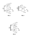
- FIGS. 3, 4, and 5 illustrate transformer-based power conversion circuits utilizing one or more controllable bridge rectifier circuits.
- FIG. 6A illustrates the regulator mode of operation for a thyristor bridge rectifier circuit.
- FIG. 6B illustrates the bypass mode of operation for a thyristor bridge rectifier circuit.
- FIG. 7 is a power conversion apparatus utilizing multiple controllable bridge rectifier circuits having a bypass mode of operation.
- FIG. 8 is another power conversion apparatus utilizing multiple controllable bridge rectifier circuits having a bypass mode of operation.
- FIGS. 9A and 9B illustrate voltage control in a power conversion apparatus utilizing multiple controllable bridge rectifier circuits having a bypass mode of operation.
- FIG. 10 plots power factor versus a varying input voltage for a conventional power conversion circuit and for a power conversion apparatus utilizing multiple controllable bridge rectifier circuits having a bypass mode of operation.
- FIG. 11 is a process flow diagram illustrating an example method for controllably converting AC to DC.
- FIG. 12 illustrates an example control circuit according to some embodiments of the present invention.
- FIG. 3 One example configuration is shown in FIG. 3 , where the AC-side terminals of each of two thyristor bridge rectifier circuits 310 are connected to respective secondary windings of a transformer, while their DC-side terminals are connected so that the DC outputs of the rectifier circuits 310 are combined in series. A phase shift between the secondary windings allows for a reduction in harmonics in the input current, and also reduces ripple in the output voltage. While each of the bridge rectifier circuits 310 may have a 6-pulse configuration like the configuration shown in FIG.
- each bridge rectifier circuit 310 in FIG. 3 has multiple connections to a set of multi-phase windings; for the 3-phase case, this connection may be either in a “wye” (or “star”) configuration or a “delta” configuration. It should be noted that this assumption applies to FIGS. 4, 5, 7, 8, 9A , and 9 B, as well; thus, every AC-side connection to a bridge rectifier circuit in these figures should be understood to be a multi-phase connection.
- FIG. 3 allows a great deal of control over the output voltage, while also allowing the power-handling requirements to be distributed across two (or more) rectifier circuits.
- the circuit operates with low power factors at rated voltage, especially when both rectifier circuits are regulating their respective output voltages to levels well below their maximum possible levels, leading to poor overall system performance.
- FIG. 4 shows a thyristor bridge rectifier circuit 310 , a diode bridge rectifier circuit may be used instead, in some applications.
- the load tap changer 410 allows the transformer to output a relatively constant AC voltage to the rectifier circuit.
- the tap changer 410 has to cover an output voltage range of 30% or more. Manufacturing a transformer with such a wide range of taps is challenging.
- FIG. 5 illustrates an approach that is similar to that of FIG. 3 , but with an IGBT-based bridge rectifier circuit 510 substituted for one of the thyristor bridge rectifier circuits 310 .
- integrated gate-commutated thyristor (IGCT)-based circuits or IGBT-based circuits can be substituted for either or both thyristor circuits 310 .
- IGBT-based or IGCT-based circuits may have a 6-pulse configuration like that illustrated in FIG. 4 , they may also have other configurations. While IGBT- and IGCT-based systems offer high performance, these circuits are more costly than their thyristor-based counterparts.
- Lower-cost, but still high-performance alternatives according to several embodiments of the present invention are based on a thyristor bridge rectifier circuit that has a bypass mode of operation, in addition to its normal, or “regulator,” mode of operation.
- the regulator mode of operation for a 6-pulse, three-phase, thyristor-based bridge rectifier circuit 600 is shown in FIG. 6A .
- a pair of diodes is conducting at any given time, but the diodes in the conducting pair are in different legs.
- the conducting diodes are shown in black.
- the regulating operation of the rectifier circuit of FIG. 6A can be controlled by adjusting the firing angle ⁇ .
- the output of the circuit 600 is its maximum output voltage, i.e., the same output voltage that would be obtained if diodes were used instead of the thyristors.
- this condition where the maximum possible output voltage of the circuit is provided, is referred to as “full-output” mode.
- the rectifier circuit regulates the output voltage, producing a positive output DC voltage that varies from the maximum rectifier voltage to just above zero volts DC.
- the output voltage is at or near zero volts DC, while firing angles ⁇ between 90 and 180 degrees produce a negative output voltage from the bridge.
- the rectifier circuit can be operated in a “protection mode,” in which the output voltage is reduced to zero by switching half of the thyristor bridges in a protection mode (with a firing angle between 90 and 180 degrees) and the other half in regular mode (with a firing angle between 0 and 90 degrees).
- a bridge rectifier circuit operated with firing angles between zero and 90 degrees, such that a non-zero voltage less than the maximum possible output voltage is provided is considered to be operating in “voltage regulating mode.” Note that the same analysis applies to 12-pulse bridge rectifier circuits, while a similar analysis can be applied to bridge rectifiers having more or fewer phases.
- the thyristors are controlled (via their gate control inputs) so that only one thyristor in any given phase leg is conducting at the same time. This is true regardless of the firing angle ⁇ .
- the controllable bridge rectifier circuit has a “bypass mode,” in which both diodes in one of the phase legs are conducting at the same time. This is shown in FIG. 6B , where controllable bridge rectifier circuit 600 is operating in bypass mode, where the thyristors in both arms of the left-most phase leg are controlled so that they are conducting simultaneously. In bypass mode, the output of the rectifier circuit 600 is nominally zero volts DC, without regard to any firing angle ⁇ .
- FIG. 6B illustrates a three-phase, six-pulse rectifier bridge, a similar bypass mode can be implemented with other configurations and with differing numbers of phases.
- FIG. 7 illustrates a power conversion apparatus 700 that includes a transformer 710 having a single primary winding, connected to an AC input, and several secondary windings.
- Each of the secondary windings is connected to a controllable bridge rectifier circuit 600 supporting both a regulator mode and a bypass mode as described above, i.e., a regulator mode in which a non-zero voltage less than or equal to the maximum rectifier voltage is supplied, and a bypass mode in which the controllable bridge rectifier circuit provides negligible voltage to its DC-side terminals and draws negligible current from its AC-side terminals.
- the DC-side terminals of the controllable bridge rectifier circuits 600 are connected in cascade, i.e., so that the DC outputs of the bridge rectifier circuits 600 are connected in series.
- controllable bridge rectifier circuits As long as one or more controllable bridge rectifier circuits are also used, with those controllable bridge rectifier circuits having a total voltage regulating range that exceeds 30% of the fixed DC voltage output of the circuit 700 , then the fixed DC voltage can be maintained while the AC input voltage varies.
- FIG. 8 illustrates another transformer-based power conversion apparatus 800 , which again includes a transformer 710 having a primary winding connected to an AC input source and multiple secondary windings (two, in this case), where each secondary winding is connected to the AC-side terminals of a controllable bridge rectifier circuit 600 .
- the output (DC-side) terminals of the controllable bridge rectifier circuits 600 are connected in cascade, so that the DC outputs from the controllable bridge rectifier circuits 600 are summed together.
- the circuit 800 of FIG. 8 includes a diode bridge rectifier circuit 810 having its AC-side terminals connected to the AC input source, i.e., to the primary winding of the transformer 710 .
- FIGS. 9A and 9B illustrate how the techniques and circuits described above can be used to produce a fixed DC output voltage from a varying AC input voltage. (It should be appreciated that the same techniques and circuits can also be used to produce a variable DC output from a fixed AC input voltage, or from a varying AC input voltage.)
- five controllable bridge rectifier circuits 600 are connected to secondary windings of transformer 710 .
- a diode bridge rectifier circuit 810 is connected to yet another secondary winding. The DC terminals from all of these rectifier circuits are connected together, so that the DC outputs are combined in series.
- the input AC voltage is 0.6 times a nominal AC voltage level.
- the diode rectifier bridge circuit 810 produces a DC output voltage of 0.6 times a nominal DC voltage level.
- the three controllable bridge rectifier circuits 600 immediately above the diode bridge rectifier circuit 810 are operating in full-output mode (i.e., with a firing angle of zero degrees), and thus each produce a DC output voltage of 0.12 times the nominal DC voltage level.
- controllable bridge rectifier circuits 600 are depicted with a diode symbol, indicating that they are operating in full-output mode.
- the controllable bridge rectifier circuit 600 immediately above these three is operating in voltage regulating mode (as indicated by the thyristor symbol), and is controlled to produce a DC output voltage of 0.04 times the nominal DC voltage level.
- the controllable bridge rectifier circuit 600 at the top of the Figure is operating in bypass mode (indicated by the absence of either a diode or thyristor symbol), and is thus producing a DC output voltage of zero, while drawing no current from the corresponding secondary winding.
- the total voltage produced by the cascade combination of the bridge rectifier circuits is 1.0 times the nominal DC voltage.
- the bridge rectifier circuits operating either in full-output mode (including the diode rectifier bridge) or in bypass mode do not inject significant reactive power back to the primary side of the transformer.
- Bridge rectifier circuits operating in voltage regulating mode do inject reactive power back to the primary side.
- the overall power factor of the circuit is quite high.
- the same DC output voltage can be maintained over a wide range of input voltages.
- the same circuit is provided with an AC input voltage of 0.9 times the nominal AC voltage level.
- the diode bridge rectifier circuit 810 thus produces a DC output voltage of 0.9 times the nominal DC output level.
- the controllable bridge rectifier circuit 600 immediately above the diode bridge rectifier circuit 810 is operating in voltage regulating mode, and is controlled to produce a DC output voltage of 0.1 times the nominal DC output level.
- the remaining controllable bridge rectifier circuits 600 are all operating in bypass mode, and are thus contributing negligible DC voltage to the overall output voltage, while drawing no current from their respective secondary windings.
- the overall DC output voltage is 1.0 times the nominal DC voltage level.
- the overall power factor is relatively high, since only one controllable bridge rectifier circuit, handling only one-tenth the overall power, is operating in voltage regulating mode.
- FIG. 10 illustrates the improvement in power factor that can be realized using a circuit like the one illustrated in FIG. 9 , compared to a conventional circuit in which controllable bridge rectifier circuits having bypass modes of operation are not used.
- the minimum power factor over a wide range of regulation can set to any desired level, simply by selecting an appropriate number of cascaded controllable bridge rectifier circuits having the bypass mode described above.
- multiple bridge rectifier circuits including one or more controllable bridge rectifier circuits having a bypass mode, can be combined and operated so as to provide a low-cost, high-performance voltage converter apparatus.
- One or several of the controllable bridge rectifier circuits can be selectively operated in bypass mode, allowing for coarse steps in voltage output, while a remaining controllable bridge rectifier is operated in voltage regulating mode, so as to provide a highly controllable output voltage.
- a high input power factor over a wide range of voltage variation can be achieved.
- controllable bridge rectifier circuits having a bypass mode as described herein may be used in systems that do not include a transformer, in some cases.
- multiple bridge rectifier circuits can be combined in cascade, in the manner described above, and connected to AC sources that are galvanically isolated from one another, i.e., having no direct conduction path between them.
- a transformer is simply one way to achieve such isolation.
- One or more bridge rectifier circuits can be connected to windings of a rotating machine, as well.
- controllable bridge rectifier circuits based at least in part on controllable switching elements other than thyristors, such as integrated gate-controlled thyristors (IGCTs) and/or gate turn-off (GTO) thyristors, may also be combined according to the techniques described herein.
- IGCTs integrated gate-controlled thyristors
- GTO gate turn-off
- embodiments of the presently described circuit include power conversion apparatus for controllably converting alternating current (AC) to direct current (DC), where an example power conversion apparatus includes multiple AC sources galvanically isolated from one another, and multiple bridge rectifier circuits, including one or more controllable bridge rectifier circuits, where each bridge rectifier has respective AC-side terminals and DC-side terminals and each bridge rectifier circuit is connected to a corresponding one of the AC sources via its AC-side terminals.
- the DC-side terminals are connected so that the outputs of the bridge rectifier circuits are combined in series.
- the power conversion apparatus includes a control circuit configured to individually control each controllable bridge rectifier circuit to selectively operate in a regulator mode, whereby a non-zero voltage less than or equal to the maximum rectifier voltage is provided by the controllable bridge rectifier circuit, and a bypass mode, whereby the controllable bridge rectifier circuit provides negligible voltage to its DC-side terminals and draws negligible current from its corresponding AC source.
- a control circuit configured to individually control each controllable bridge rectifier circuit to selectively operate in a regulator mode, whereby a non-zero voltage less than or equal to the maximum rectifier voltage is provided by the controllable bridge rectifier circuit, and a bypass mode, whereby the controllable bridge rectifier circuit provides negligible voltage to its DC-side terminals and draws negligible current from its corresponding AC source.
- FIG. 12 An example configuration for such a control circuit is illustrated in FIG. 12 and described in detail below; it will be appreciated that conventional control circuits for operating controllable bridge rectifier circuits can be readily modified to control
- the power conversion apparatus described in general terms above may include a transformer having a primary winding configured for connection to an AC source and at least one output winding.
- at least one of the bridge rectifier circuits has its AC-side terminals connected across one of the output windings.
- one of the bridge rectifier circuits has its AC-side terminals connected to the primary winding; one non-limiting example of such a configuration is shown in FIG. 8 and was described in detail above.
- At least one of the bridge rectifier circuits is a diode rectifier circuit.
- the multiple bridge rectifier circuits include at least two controllable bridge rectifier circuits, where the regulator mode for each of the at least two controllable bridge rectifier comprises a voltage regulating mode and a full output mode, and where the control circuit is configured to control the at least two controllable bridge rectifier circuits so that only one of the controllable bridge rectifier circuits is operating in voltage regulating mode at any given time, while each of the remaining controllable bridge rectifier circuits is operating in either bypass mode or full output mode.
- Non-limiting examples of these embodiments were shown in FIGS.
- control circuit is configured to control the at least two controllable bridge rectifier circuits so as to successively operate a different one of the at least two controllable bridge rectifier circuits in voltage regulating mode, while each of the remaining controllable bridge rectifier circuits is operating in either bypass mode or full output mode.
- one or more of the controllable bridge rectifier circuits may be a thyristor bridge rectifier, where the control circuit is configured to control the thyristor bridge rectifier to operate in bypass mode by triggering thyristors in both arms of a single phase leg to conduct simultaneously.
- bypass mode can use any of the phase legs.
- the control circuit in these embodiments is configured to control the thyristor bridge rectifier(s) in bypass mode by successively triggering thyristors so as to rotate a bypass leg among multiple phase legs of the thyristor bridge rectifier.
- FIG. 11 is a process flow diagram illustrating an example of such embodiments, i.e., a method for controllably converting alternating current (AC) to direct current (DC).
- the illustrated method includes providing a plurality of AC sources, galvanically isolated from one another.
- a plurality of bridge rectifier circuits is also provided, including one or more controllable bridge rectifier circuits.
- Each bridge rectifier has respective AC-side terminals and DC-side terminals, and each bridge rectifier circuit is connected to a corresponding one of the AC source.
- the method further includes individually controlling each controllable bridge rectifier circuit to selectively operate in a regulator mode, whereby a non-zero voltage less than or equal to the maximum rectifier voltage is provided by the controllable bridge rectifier circuit, and a bypass mode, whereby the controllable bridge rectifier circuit provides zero voltage to its DC-side terminals and draws negligible current from its corresponding AC source.
- a first one of the bridge rectifier circuits is a diode rectifier circuit.
- the plurality of bridge rectifier circuits includes at least two controllable bridge rectifier circuits, wherein the regulator mode for each of the at least two controllable bridge rectifier comprises a voltage regulating mode and a full output mode, and the at least two controllable bridge rectifier circuits are controlled so that only one of the controllable bridge rectifier circuits is operating in voltage regulating mode at any given time, while each of the remaining controllable bridge rectifier circuits is operating in either bypass mode or full output mode.
- the at least two controllable bridge rectifier circuits are controlled so as to successively operate a different one of the at least two controllable bridge rectifier circuits in voltage regulating mode, while each of the remaining controllable bridge rectifier circuits is operating in either bypass mode or full output mode.
- a first controllable bridge rectifier circuit is a thyristor bridge rectifier, which is controlled to operate in bypass mode by triggering thyristors in both arms of a single phase leg to conduct simultaneously.
- the thyristor bridge rectifier is controlled to operate in bypass mode by successively triggering thyristors so as to rotate a bypass leg among multiple phase legs of the thyristor bridge rectifier.
- various embodiments of the present invention include a control circuit configured to individually control each controllable bridge rectifier circuit to selectively operate in a regulator mode, whereby a non-zero voltage less than or equal to the maximum rectifier voltage is provided by the controllable bridge rectifier circuit, and a bypass mode, whereby the controllable bridge rectifier circuit provides negligible voltage to its DC-side terminals and draws negligible current from its corresponding AC source.
- FIG. 12 illustrates one possible configuration for such a control circuit.
- Control circuit 1200 shown in FIG. 12 , includes a microprocessor 1210 , memory 1220 , and digital/analog hardware circuit 1230 .
- hardware circuit 1230 outputs a set of gate control voltages g1, g2, . . . , g6, which are sufficient to control a single, 6-pulse, bridge rectifier circuit.
- control circuit 1200 may be readily extended to provide control voltages for multiple 6-pulse bridge rectifiers and/or to control one or more controllable bridge rectifier circuits.
- a voltage sense line from the AC input of the power-converter circuit may also be provide—this may be used in some embodiments to assist the microprocessor in selecting which (if any) of several controllable bridge rectifier circuits to operate in full-power mode, which (if any) to operate in bypass mode, and which to operate in voltage regulating mode.
- Hardware 1230 thus includes one or more analog-to-digital (A/D) converters, in some embodiments, to convert the analog signals on the one or more voltage sense lines to digital signals suitable for use by microprocessor 1210 .
- A/D analog-to-digital
- FIG. 12 may employ a microcontroller device that incorporates not only a processor element but one or more A/D converters, in which case A/D converters need not be provided in separate hardware.
- Microprocessor 1210 is configured, using program instructions stored in memory 1220 , to control at least one controllable bridge rectifier circuit according to the techniques detailed above, i.e., to selectively operate in a regulator mode, whereby a non-zero voltage less than or equal to the maximum rectifier voltage is provided by the controllable bridge rectifier circuit, and a bypass mode, whereby the controllable bridge rectifier circuit provides negligible voltage to its DC-side terminals and draws negligible current from its corresponding AC source.
- Memory circuit 1220 may comprise one or several memory devices and/or memory types, such as flash memory or other non-volatile memory, random-access memory (RAM), read-only memory (ROM), etc.
- control circuit shown in FIG. 12 is but one example of a circuit that can be adapted to control one or more controllable bridge rectifier circuits according to the techniques described herein.
- Control circuits developed to control conventional controllable bridge rectifier circuits can be readily adapted to further support a bypass mode, for example, and adapted to include logic for determining which of multiple controllable rectifiers should be operated in bypass mode, full-output mode, or voltage regulating mode.
- Other information and/or signals supplied to the control circuit may also be used to make or refine these decisions.
- information or signaling indicating a DC fault downstream from the DC output of one of the power conversion devices described above may trigger the control circuit to reduce the output voltage, e.g., by placing some or all of the controllable bridge rectifiers in bypass mode, and/or operating one or more of the controllable bridge rectifiers in a protection mode.
- Other variants and modifications of the techniques detailed herein will be apparent to those skilled in the art of power converter and HVDC system design.
- a power-conversion circuit constructed and operated according to the techniques detailed herein can operate at a significantly higher power factor, over a wide range of voltages.
- the circuits described herein can be of lower cost than circuits that utilize higher-cost control devices such as IGBTs.
- Some of the circuits and techniques described herein can also be used to reduce the size and cost of the transformer used in a power conversion apparatus, since complicated and expensive load tap changers can be avoided.
- the use of multiple windings, rather than multiple taps, can also result in transformer-based systems that are easier to manufacture, and more reliable.
- press-pack diodes and/or thyristors are used in the described circuits, then failed modules are easily bypassed without external bypass devices (e.g., compared to modular implementations of rectifiers that use industrial IGBTs, as illustrated in FIG. 2 ), since press-pack diodes and thyristors fail short.
Abstract
Description
where Vpeak is the peak value of the phase (line-to-neutral) input voltages and a is the firing angle of the thyristors, i.e., the phase angle, relative to the zero-crossing point of the AC waveform in a given thyristor's phase leg, at which the thyristor is triggered into conduction. If the commutating inductances are considered and assumed to have an inductance of Ld, then the output voltage is a function of the DC load current Id, and is given by
where f is the AC frequency.
Claims (13)
Priority Applications (3)
| Application Number | Priority Date | Filing Date | Title |
|---|---|---|---|
| US14/057,760 US9614457B2 (en) | 2013-10-18 | 2013-10-18 | Modular thyristor-based rectifier circuits |
| EP14790462.7A EP3058649B1 (en) | 2013-10-18 | 2014-10-16 | Modular thyristor-based rectifier circuits |
| PCT/US2014/060859 WO2015057940A1 (en) | 2013-10-18 | 2014-10-16 | Modular thyristor-based rectifier circuits |
Applications Claiming Priority (1)
| Application Number | Priority Date | Filing Date | Title |
|---|---|---|---|
| US14/057,760 US9614457B2 (en) | 2013-10-18 | 2013-10-18 | Modular thyristor-based rectifier circuits |
Publications (2)
| Publication Number | Publication Date |
|---|---|
| US20150109837A1 US20150109837A1 (en) | 2015-04-23 |
| US9614457B2 true US9614457B2 (en) | 2017-04-04 |
Family
ID=51830659
Family Applications (1)
| Application Number | Title | Priority Date | Filing Date |
|---|---|---|---|
| US14/057,760 Active 2034-09-02 US9614457B2 (en) | 2013-10-18 | 2013-10-18 | Modular thyristor-based rectifier circuits |
Country Status (3)
| Country | Link |
|---|---|
| US (1) | US9614457B2 (en) |
| EP (1) | EP3058649B1 (en) |
| WO (1) | WO2015057940A1 (en) |
Families Citing this family (8)
| Publication number | Priority date | Publication date | Assignee | Title |
|---|---|---|---|---|
| US9571022B2 (en) * | 2013-08-30 | 2017-02-14 | Abb Schweiz Ag | Electrical generator with integrated hybrid rectification system comprising active and passive rectifiers connected in series |
| WO2015134494A2 (en) * | 2014-03-07 | 2015-09-11 | The Regents Of The University Of California | Method and system for dynamic intelligent load balancing |
| US10404157B2 (en) * | 2016-01-07 | 2019-09-03 | Toshiba Mitsubishi-Electric Industrial Systems Corporation | AC-DC conversion device and method for controlling same by controlling the timing of multiple switch portions |
| EP3211782A1 (en) | 2016-02-24 | 2017-08-30 | Hydrogenics Europe NV | Configurable ac dc converter |
| WO2017179127A1 (en) * | 2016-04-12 | 2017-10-19 | 東芝三菱電機産業システム株式会社 | Control device for power conversion device |
| CN107482760B (en) * | 2016-06-08 | 2020-06-30 | 光宝电子(广州)有限公司 | Switching device |
| CN110366812B (en) * | 2017-01-11 | 2021-11-26 | 日立能源瑞士股份公司 | Method and system for fault handling in DC power transmission |
| CN109873568A (en) * | 2019-02-19 | 2019-06-11 | 南京南瑞继保电气有限公司 | A kind of more DC port inverters and control method |
Citations (69)
| Publication number | Priority date | Publication date | Assignee | Title |
|---|---|---|---|---|
| US3764815A (en) | 1971-03-06 | 1973-10-09 | Siemens Ag | Start-up converter |
| US3909697A (en) * | 1973-08-04 | 1975-09-30 | Bbc Brown Boveri & Cie | Arrangement for supplying direct current to a consumer from an alternating current source with interposed transformer and rectifier establishing periodic rapid changes in transformation ratio |
| US4335424A (en) * | 1980-08-25 | 1982-06-15 | Zivan Zabar | Cycling firing method for bypass operation of bridge converters |
| US5170334A (en) | 1990-10-12 | 1992-12-08 | Kabushiki Kaisha Toshiba | Bypass-pair control apparatus for thyristor bridge |
| JPH06249828A (en) | 1993-02-24 | 1994-09-09 | Tohoku Electric Power Co Inc | Detection of carbide in low alloy steel by electrochemical polarization method |
| US5446643A (en) * | 1992-05-11 | 1995-08-29 | Electric Power Research Institute, Inc. | Harmonic blocking converter system |
| US5715151A (en) | 1995-09-12 | 1998-02-03 | Kabushiki Kaisha Toshiba | Control and protection system for AC-DC conversion system |
| WO2001025628A2 (en) | 1999-10-07 | 2001-04-12 | Vestas Wind Systems A/S | Wind power plant |
| US20020079706A1 (en) | 2000-05-23 | 2002-06-27 | Rebsdorf Anders V. | Variable speed wind turbine having a matrix converter |
| US6434020B1 (en) | 2001-04-09 | 2002-08-13 | Hydro-Quebec | Apparatus and method of operating two switches connecting respectively a load to power source terminals in response to a switch control signal |
| US6487096B1 (en) | 1997-09-08 | 2002-11-26 | Capstone Turbine Corporation | Power controller |
| US20040080164A1 (en) | 2001-12-07 | 2004-04-29 | Mckelvey Terence | Turbine generator starting method and turbine generation system |
| US6958550B2 (en) | 1998-04-02 | 2005-10-25 | Capstone Turbine Corporation | Method and system for control of turbogenerator power and temperature |
| US20060192390A1 (en) | 2003-07-15 | 2006-08-31 | Javier Juanarena Saragueta | Control and protection of a doubly-fed induction generator system |
| US7218012B1 (en) | 2006-05-31 | 2007-05-15 | General Electric Company | Emergency pitch drive power supply |
| US20070132248A1 (en) | 2005-12-08 | 2007-06-14 | General Electric Company | System and method of operating double fed induction generators |
| US20070228836A1 (en) | 2006-03-30 | 2007-10-04 | Ralph Teichmann | Power generation system and method |
| US20080001408A1 (en) | 2006-06-30 | 2008-01-03 | Yan Liu | Systems and methods for an integrated electrical sub-system powered by wind energy |
| US20080129120A1 (en) | 2006-11-30 | 2008-06-05 | Industrial Technology Research Institute | Device for controlling single-phase power conditioner for renewable energy system |
| US7397143B2 (en) | 2006-06-19 | 2008-07-08 | General Electric Company | Methods and apparatus for supplying and/or absorbing reactive power |
| US20080252267A1 (en) | 2006-10-27 | 2008-10-16 | Airbus France | Device for supplying electrical power to an aircraft and for electrically starting a jet engine on board an aircraft |
| US7449794B2 (en) | 2006-12-18 | 2008-11-11 | Industrial Technology Research Institute | Wind turbine with self-contained power system |
| US20080303489A1 (en) | 2007-06-08 | 2008-12-11 | Jung-Woo Park | Controller of doubly-fed induction generator |
| WO2009110648A1 (en) | 2008-03-06 | 2009-09-11 | Jun Sung Electronics Co., Ltd | Converter for hvdc |
| US20090230689A1 (en) | 2008-03-13 | 2009-09-17 | General Electric | Wind turbine energy storage and frequency control |
| US7602074B2 (en) | 2004-05-18 | 2009-10-13 | Nordex Energy Gmbh | Wind power installation having an auxiliary generator and method for the control thereof |
| EP2114001A1 (en) | 2008-04-30 | 2009-11-04 | TREVI ENERGY S.p.A. | A modular converter for converting the electric power produced by aerogenerators, and a wind-power plant that uses said converter |
| US20090322083A1 (en) * | 2008-06-30 | 2009-12-31 | General Electric Company | Optimizing converter protection for wind turbine generators |
| US20100045040A1 (en) | 2007-04-30 | 2010-02-25 | Bendixen Flemming Buus | Variable Speed Wind Turbine With Doubly-Fed Induction Generator Compensated For Varying Rotor Speed |
| US20100060000A1 (en) | 2008-09-08 | 2010-03-11 | Scholte-Wassink Hartmut | Wind turbine having a main power converter and an auxiliary power converter and a method for the control thereof |
| EP2166225A1 (en) | 2008-09-19 | 2010-03-24 | Vestas Wind Systems A/S | A turbine farm having an auxiliary power supply |
| US20100124087A1 (en) | 2008-11-15 | 2010-05-20 | Sma Solar Technology Ag | Power converter start-up circuit |
| US20100270864A1 (en) | 2009-04-22 | 2010-10-28 | General Electric Company | Genset system with energy storage for transient response |
| US20110013441A1 (en) | 2009-07-15 | 2011-01-20 | Rainer Gruber | Static converter and method for starting up the converter |
| US20110042965A1 (en) | 2008-02-21 | 2011-02-24 | Magnomatics Limited | Wind turbine power train |
| US20110049994A1 (en) | 2008-05-07 | 2011-03-03 | Siemens Aktiengesellschaft | Wind farm having a plurality of wind energy installations |
| US20110057631A1 (en) | 2009-09-07 | 2011-03-10 | Luca Dalessandro | Static exciter of an electric generator, method for retrofitting, and method for operating |
| US20110057443A1 (en) | 2006-03-17 | 2011-03-10 | Gregorio Rivas | Collector anti-wearing and lubrication system for variable speed wind turbine |
| WO2011058170A1 (en) | 2009-11-16 | 2011-05-19 | Vestas Wind Systems A/S | Method and device for operation of a wind power plant |
| US20110140534A1 (en) | 2010-05-28 | 2011-06-16 | Mitsubishi Heavy Industries, Ltd. | Power supply device and method |
| CN201966683U (en) | 2010-12-02 | 2011-09-07 | 中达电通股份有限公司 | Wind power generation system |
| US8018083B2 (en) | 2010-08-05 | 2011-09-13 | General Electric Company | HVDC connection of wind turbine |
| WO2011124258A1 (en) | 2010-04-08 | 2011-10-13 | Areva T&D Uk Ltd | Hybrid hvdc converter |
| US20110291479A1 (en) | 2010-06-01 | 2011-12-01 | Samsung Sdi Co., Ltd. | Energy storage system and method of controlling the same |
| WO2012026026A1 (en) | 2010-08-26 | 2012-03-01 | 三菱電機株式会社 | Vehicle control device and diesel/hybrid vehicle system |
| US8138620B2 (en) | 2009-06-12 | 2012-03-20 | General Electric Company | Methods and systems for operating a wind turbine power converter |
| CN202172281U (en) | 2011-08-16 | 2012-03-21 | 国电联合动力技术有限公司 | Grid-connected wind generating set |
| US20120139246A1 (en) | 2009-08-14 | 2012-06-07 | Suzlon Energy Gmbh | Asynchronous generator system and wind turbine having an asynchronous generator system |
| WO2012103894A2 (en) | 2011-02-04 | 2012-08-09 | Vestas Wind Systems A/S | A wind turbine arrangement with a main wind turbine and at least one secondary wind turbine |
| US20120280665A1 (en) | 2010-01-11 | 2012-11-08 | Sinovel Wind Group Co.,Ltd. | Control method for low voltage ride through |
| US20120286512A1 (en) | 2010-12-21 | 2012-11-15 | Ge Energy Products France Snc | Electricity production system |
| US8330296B2 (en) | 2008-04-15 | 2012-12-11 | Candew Scientific, Llc | Hybrid renewable energy turbine using wind and solar power |
| US20130016537A1 (en) | 2011-07-14 | 2013-01-17 | Heng Deng | Method for controlling a frequency converter and frequency converter |
| US20130027994A1 (en) | 2010-03-11 | 2013-01-31 | Siemens Aktiengesellschaft | Method and system for damping subsynchronous resonant oscillations in a power system using a wind turbine |
| EP2565443A1 (en) | 2011-09-05 | 2013-03-06 | XEMC Darwind B.V. | Generating auxiliary power for a wind turbine |
| US20130082628A1 (en) | 2011-06-13 | 2013-04-04 | Tdk Corporation | Dc-dc converter |
| US8436490B2 (en) | 2005-08-30 | 2013-05-07 | Abb Research Ltd. | Wind mill power flow control with dump load and power converter |
| US20130113212A1 (en) | 2010-06-30 | 2013-05-09 | Hitachi, Ltd. | Wind Power Generator System, and Control Method for the Same |
| US20130184884A1 (en) | 2011-07-20 | 2013-07-18 | Inventus Holdings, Llc | Dispatchable renewable energy generation, control and storage facility |
| US20130181688A1 (en) | 2010-10-06 | 2013-07-18 | Raven Energy Alternatives, Llc | System and method for variable speed generation of controlled high-voltage dc power |
| US20130193766A1 (en) | 2012-01-31 | 2013-08-01 | Atlantic Grid Operations A., Llc | Control and protection of a dc power grid |
| US20130200620A1 (en) | 2010-06-30 | 2013-08-08 | Vestas Wind Systems A/S | Wind turbine |
| US20130200617A1 (en) | 2010-04-06 | 2013-08-08 | GE Energy Power Conversion Tecnology Ltd | Power transmission systems |
| US20130208522A1 (en) | 2012-02-13 | 2013-08-15 | Ge Energy Power Conversion Technology Ltd. | Power Supply for a Charge and Electricity Production Plant |
| US20130264882A1 (en) | 2012-04-04 | 2013-10-10 | Gamesa Innovation & Technology, S.L. | Power generation and distribution system for a wind turbine |
| US20130285491A1 (en) | 2012-04-27 | 2013-10-31 | Raytheon Company | Electro-mechanical kinetic energy storage device and method of operation |
| US20130343111A1 (en) | 2012-06-20 | 2013-12-26 | Robert J. Nelson | Power generation and transmission system |
| US20140152109A1 (en) | 2012-11-30 | 2014-06-05 | General Electric Company | Medium voltage uninterruptible power supply |
| US20150001848A1 (en) | 2012-01-18 | 2015-01-01 | Hitachi, Ltd. | Wind Turbine Generation System |
-
2013
- 2013-10-18 US US14/057,760 patent/US9614457B2/en active Active
-
2014
- 2014-10-16 EP EP14790462.7A patent/EP3058649B1/en active Active
- 2014-10-16 WO PCT/US2014/060859 patent/WO2015057940A1/en active Application Filing
Patent Citations (77)
| Publication number | Priority date | Publication date | Assignee | Title |
|---|---|---|---|---|
| US3764815A (en) | 1971-03-06 | 1973-10-09 | Siemens Ag | Start-up converter |
| US3909697A (en) * | 1973-08-04 | 1975-09-30 | Bbc Brown Boveri & Cie | Arrangement for supplying direct current to a consumer from an alternating current source with interposed transformer and rectifier establishing periodic rapid changes in transformation ratio |
| US4335424A (en) * | 1980-08-25 | 1982-06-15 | Zivan Zabar | Cycling firing method for bypass operation of bridge converters |
| US5170334A (en) | 1990-10-12 | 1992-12-08 | Kabushiki Kaisha Toshiba | Bypass-pair control apparatus for thyristor bridge |
| US5446643A (en) * | 1992-05-11 | 1995-08-29 | Electric Power Research Institute, Inc. | Harmonic blocking converter system |
| JPH06249828A (en) | 1993-02-24 | 1994-09-09 | Tohoku Electric Power Co Inc | Detection of carbide in low alloy steel by electrochemical polarization method |
| US5715151A (en) | 1995-09-12 | 1998-02-03 | Kabushiki Kaisha Toshiba | Control and protection system for AC-DC conversion system |
| US6487096B1 (en) | 1997-09-08 | 2002-11-26 | Capstone Turbine Corporation | Power controller |
| US6958550B2 (en) | 1998-04-02 | 2005-10-25 | Capstone Turbine Corporation | Method and system for control of turbogenerator power and temperature |
| WO2001025628A2 (en) | 1999-10-07 | 2001-04-12 | Vestas Wind Systems A/S | Wind power plant |
| US20020079706A1 (en) | 2000-05-23 | 2002-06-27 | Rebsdorf Anders V. | Variable speed wind turbine having a matrix converter |
| US20040026929A1 (en) | 2000-05-23 | 2004-02-12 | Vestas Wind Systems A/S | Variable speed wind turbine having a matrix converter |
| US6434020B1 (en) | 2001-04-09 | 2002-08-13 | Hydro-Quebec | Apparatus and method of operating two switches connecting respectively a load to power source terminals in response to a switch control signal |
| US20040080164A1 (en) | 2001-12-07 | 2004-04-29 | Mckelvey Terence | Turbine generator starting method and turbine generation system |
| US20060192390A1 (en) | 2003-07-15 | 2006-08-31 | Javier Juanarena Saragueta | Control and protection of a doubly-fed induction generator system |
| US7602074B2 (en) | 2004-05-18 | 2009-10-13 | Nordex Energy Gmbh | Wind power installation having an auxiliary generator and method for the control thereof |
| US8436490B2 (en) | 2005-08-30 | 2013-05-07 | Abb Research Ltd. | Wind mill power flow control with dump load and power converter |
| US20070132248A1 (en) | 2005-12-08 | 2007-06-14 | General Electric Company | System and method of operating double fed induction generators |
| US20110057443A1 (en) | 2006-03-17 | 2011-03-10 | Gregorio Rivas | Collector anti-wearing and lubrication system for variable speed wind turbine |
| US20070228836A1 (en) | 2006-03-30 | 2007-10-04 | Ralph Teichmann | Power generation system and method |
| US7218012B1 (en) | 2006-05-31 | 2007-05-15 | General Electric Company | Emergency pitch drive power supply |
| US7397143B2 (en) | 2006-06-19 | 2008-07-08 | General Electric Company | Methods and apparatus for supplying and/or absorbing reactive power |
| US20080001408A1 (en) | 2006-06-30 | 2008-01-03 | Yan Liu | Systems and methods for an integrated electrical sub-system powered by wind energy |
| US20080252267A1 (en) | 2006-10-27 | 2008-10-16 | Airbus France | Device for supplying electrical power to an aircraft and for electrically starting a jet engine on board an aircraft |
| US20080129120A1 (en) | 2006-11-30 | 2008-06-05 | Industrial Technology Research Institute | Device for controlling single-phase power conditioner for renewable energy system |
| US7449794B2 (en) | 2006-12-18 | 2008-11-11 | Industrial Technology Research Institute | Wind turbine with self-contained power system |
| US20100045040A1 (en) | 2007-04-30 | 2010-02-25 | Bendixen Flemming Buus | Variable Speed Wind Turbine With Doubly-Fed Induction Generator Compensated For Varying Rotor Speed |
| US20080303489A1 (en) | 2007-06-08 | 2008-12-11 | Jung-Woo Park | Controller of doubly-fed induction generator |
| US20110042965A1 (en) | 2008-02-21 | 2011-02-24 | Magnomatics Limited | Wind turbine power train |
| WO2009110648A1 (en) | 2008-03-06 | 2009-09-11 | Jun Sung Electronics Co., Ltd | Converter for hvdc |
| US7952232B2 (en) | 2008-03-13 | 2011-05-31 | General Electric Company | Wind turbine energy storage and frequency control |
| US20090230689A1 (en) | 2008-03-13 | 2009-09-17 | General Electric | Wind turbine energy storage and frequency control |
| US8330296B2 (en) | 2008-04-15 | 2012-12-11 | Candew Scientific, Llc | Hybrid renewable energy turbine using wind and solar power |
| EP2114001A1 (en) | 2008-04-30 | 2009-11-04 | TREVI ENERGY S.p.A. | A modular converter for converting the electric power produced by aerogenerators, and a wind-power plant that uses said converter |
| US8174138B2 (en) | 2008-04-30 | 2012-05-08 | Trevi Energy S.P.A. | Modular converter for converting the electric power produced by aerogenerators, and wind-power plant that uses said converter |
| US20110049994A1 (en) | 2008-05-07 | 2011-03-03 | Siemens Aktiengesellschaft | Wind farm having a plurality of wind energy installations |
| EP2283233B1 (en) | 2008-05-07 | 2011-10-05 | Siemens Aktiengesellschaft | Wind power plant and wind farm comprising plurality of wind power plants |
| US20090322083A1 (en) * | 2008-06-30 | 2009-12-31 | General Electric Company | Optimizing converter protection for wind turbine generators |
| US20100060000A1 (en) | 2008-09-08 | 2010-03-11 | Scholte-Wassink Hartmut | Wind turbine having a main power converter and an auxiliary power converter and a method for the control thereof |
| US8188610B2 (en) | 2008-09-08 | 2012-05-29 | General Electric Company | Wind turbine having a main power converter and an auxiliary power converter and a method for the control thereof |
| EP2166225A1 (en) | 2008-09-19 | 2010-03-24 | Vestas Wind Systems A/S | A turbine farm having an auxiliary power supply |
| US20110175355A1 (en) | 2008-09-19 | 2011-07-21 | Vestas Wind Systems A/S | Turbine farm having an auxiliary power supply |
| US20100124087A1 (en) | 2008-11-15 | 2010-05-20 | Sma Solar Technology Ag | Power converter start-up circuit |
| US20100270864A1 (en) | 2009-04-22 | 2010-10-28 | General Electric Company | Genset system with energy storage for transient response |
| US8138620B2 (en) | 2009-06-12 | 2012-03-20 | General Electric Company | Methods and systems for operating a wind turbine power converter |
| US20110013441A1 (en) | 2009-07-15 | 2011-01-20 | Rainer Gruber | Static converter and method for starting up the converter |
| US20120139246A1 (en) | 2009-08-14 | 2012-06-07 | Suzlon Energy Gmbh | Asynchronous generator system and wind turbine having an asynchronous generator system |
| US20110057631A1 (en) | 2009-09-07 | 2011-03-10 | Luca Dalessandro | Static exciter of an electric generator, method for retrofitting, and method for operating |
| WO2011058170A1 (en) | 2009-11-16 | 2011-05-19 | Vestas Wind Systems A/S | Method and device for operation of a wind power plant |
| US20120280665A1 (en) | 2010-01-11 | 2012-11-08 | Sinovel Wind Group Co.,Ltd. | Control method for low voltage ride through |
| US20130027994A1 (en) | 2010-03-11 | 2013-01-31 | Siemens Aktiengesellschaft | Method and system for damping subsynchronous resonant oscillations in a power system using a wind turbine |
| US20130200617A1 (en) | 2010-04-06 | 2013-08-08 | GE Energy Power Conversion Tecnology Ltd | Power transmission systems |
| WO2011124258A1 (en) | 2010-04-08 | 2011-10-13 | Areva T&D Uk Ltd | Hybrid hvdc converter |
| US20110140534A1 (en) | 2010-05-28 | 2011-06-16 | Mitsubishi Heavy Industries, Ltd. | Power supply device and method |
| US20110291479A1 (en) | 2010-06-01 | 2011-12-01 | Samsung Sdi Co., Ltd. | Energy storage system and method of controlling the same |
| US20130200620A1 (en) | 2010-06-30 | 2013-08-08 | Vestas Wind Systems A/S | Wind turbine |
| US20130113212A1 (en) | 2010-06-30 | 2013-05-09 | Hitachi, Ltd. | Wind Power Generator System, and Control Method for the Same |
| US8018083B2 (en) | 2010-08-05 | 2011-09-13 | General Electric Company | HVDC connection of wind turbine |
| US20130154264A1 (en) | 2010-08-26 | 2013-06-20 | Mitsubishi Electric Corporation | Vehicle control device and diesel hybrid vehicle system |
| WO2012026026A1 (en) | 2010-08-26 | 2012-03-01 | 三菱電機株式会社 | Vehicle control device and diesel/hybrid vehicle system |
| US20130181688A1 (en) | 2010-10-06 | 2013-07-18 | Raven Energy Alternatives, Llc | System and method for variable speed generation of controlled high-voltage dc power |
| CN201966683U (en) | 2010-12-02 | 2011-09-07 | 中达电通股份有限公司 | Wind power generation system |
| US20120286512A1 (en) | 2010-12-21 | 2012-11-15 | Ge Energy Products France Snc | Electricity production system |
| WO2012103894A2 (en) | 2011-02-04 | 2012-08-09 | Vestas Wind Systems A/S | A wind turbine arrangement with a main wind turbine and at least one secondary wind turbine |
| US20130082628A1 (en) | 2011-06-13 | 2013-04-04 | Tdk Corporation | Dc-dc converter |
| US20130016537A1 (en) | 2011-07-14 | 2013-01-17 | Heng Deng | Method for controlling a frequency converter and frequency converter |
| US20130184884A1 (en) | 2011-07-20 | 2013-07-18 | Inventus Holdings, Llc | Dispatchable renewable energy generation, control and storage facility |
| CN202172281U (en) | 2011-08-16 | 2012-03-21 | 国电联合动力技术有限公司 | Grid-connected wind generating set |
| US20140225369A1 (en) | 2011-09-05 | 2014-08-14 | Xemc Darwind B.V. | Generating auxiliary power for a wind turbine |
| EP2565443A1 (en) | 2011-09-05 | 2013-03-06 | XEMC Darwind B.V. | Generating auxiliary power for a wind turbine |
| US20150001848A1 (en) | 2012-01-18 | 2015-01-01 | Hitachi, Ltd. | Wind Turbine Generation System |
| US20130193766A1 (en) | 2012-01-31 | 2013-08-01 | Atlantic Grid Operations A., Llc | Control and protection of a dc power grid |
| US20130208522A1 (en) | 2012-02-13 | 2013-08-15 | Ge Energy Power Conversion Technology Ltd. | Power Supply for a Charge and Electricity Production Plant |
| US20130264882A1 (en) | 2012-04-04 | 2013-10-10 | Gamesa Innovation & Technology, S.L. | Power generation and distribution system for a wind turbine |
| US20130285491A1 (en) | 2012-04-27 | 2013-10-31 | Raytheon Company | Electro-mechanical kinetic energy storage device and method of operation |
| US20130343111A1 (en) | 2012-06-20 | 2013-12-26 | Robert J. Nelson | Power generation and transmission system |
| US20140152109A1 (en) | 2012-11-30 | 2014-06-05 | General Electric Company | Medium voltage uninterruptible power supply |
Non-Patent Citations (6)
| Title |
|---|
| Chen, Z., et al., "A Review of the State of the Art of Power Electronics for Wind Turbines," IEEE Transactions on Power Electronics, Aug. 2009, pp. 1859-1875, vol. 24, No. 8, IEEE Power Electronics Society. |
| Fletcher, J., et al., "Introduction to Doubly-Fed Induction Generator for Wind Power Applications," Paths to Sustainable Energy, Dec. 30, 2010, pp. 259-278, InTech. |
| Keshavarz, S. "Design and Evaluation of an Active Rectifier for a 4.1 MW Off-Shore Wind Turbine," Master of Science Thesis, Chalmers University of Technology, 2011, pp. a-42, Göteborg, Sweden. |
| Pekarek, S., et al., "ACSL/Graphic Modeller component models for electric power education," IEEE Transactions on Education, Nov. 1998, Subsection D. "Six-pulse bride rectifier," vol. 41, No. 4, IEEE Education Society. |
| Xiang, D. et al., "Coordinated Control of an HVDC Link and Doubly Fed Induction Generators in a Large Offshore Wind Farm", IEEE Transactions on Power Delivery, vol. 21, No. 1, Jan. 2006, pp. 463-471. |
| Zargari, Navid R. et al., "A Multilevel Thyristor Rectifier with Improved Power Factor", IEEE Transactions on Industry Applications, vol. 33, No. 5, Sep./Oct. 1997, 1208-1213. |
Also Published As
| Publication number | Publication date |
|---|---|
| US20150109837A1 (en) | 2015-04-23 |
| EP3058649B1 (en) | 2020-04-15 |
| EP3058649A1 (en) | 2016-08-24 |
| WO2015057940A1 (en) | 2015-04-23 |
Similar Documents
| Publication | Publication Date | Title |
|---|---|---|
| US9614457B2 (en) | Modular thyristor-based rectifier circuits | |
| Siwakoti et al. | A novel seven-level active neutral-point-clamped converter with reduced active switching devices and DC-link voltage | |
| US9479075B2 (en) | Multilevel converter system | |
| US6747881B2 (en) | Frequency converter | |
| US7050311B2 (en) | Multilevel converter based intelligent universal transformer | |
| DK1553689T3 (en) | Rectifier circuit for generators with dynamic variable output power | |
| US9252681B2 (en) | Power converter with a first string having controllable semiconductor switches and a second string having switching modules | |
| US9577544B2 (en) | Device and method for connecting an electric power generator to an HVDC transmission system | |
| US10998829B2 (en) | True DC current source | |
| Iqbal et al. | Multiphase converters | |
| Wang et al. | A simple 36-pulse rectifier with passive pulse-tripling circuit at the DC side | |
| US9515574B2 (en) | Modular embedded multi-level converter with midpoint balancing | |
| US9837926B2 (en) | Rectifier for converting three-phase AC voltage to 12-pulse DC voltage | |
| US9325273B2 (en) | Method and system for driving electric machines | |
| Mohan et al. | A new control strategy for active and reactive power control of three-level VSC based HVDC system | |
| Lopes et al. | A high-power PWM quadrature booster phase shifter based on a multimodule AC controller | |
| Rivera et al. | Three-Phase AC-DC Converters with Passive, Active and Hybrid Current Injection Circuits-Part I | |
| RU2660131C1 (en) | Multilevel voltage rectifier | |
| JP5752580B2 (en) | Power converter | |
| Chen et al. | A solid-state synchronous voltage source with low harmonic distortion | |
| Ukil et al. | Components and Architectures of DC Grid for Various Applications | |
| Meng et al. | Two Low-Loss Large Current Rectifiers Based on Low KVA Rating Wye-Connected Autotransformers | |
| CN115706539A (en) | Bidirectional medium voltage converter topology | |
| WO2020007516A1 (en) | Improved modular multilevel converter | |
| Rohit et al. | Voltage regulation by two level 48-pulse VSCs based STATCOM |
Legal Events
| Date | Code | Title | Description |
|---|---|---|---|
| AS | Assignment |
Owner name: ABB TECHNOLOGY AG, SWITZERLAND Free format text: ASSIGNMENT OF ASSIGNORS INTEREST;ASSIGNORS:PAN, ZHIGUO;BALA, SANDEEP;REEL/FRAME:031437/0542 Effective date: 20131017 |
|
| AS | Assignment |
Owner name: ABB SCHWEIZ AG, SWITZERLAND Free format text: MERGER;ASSIGNOR:ABB TECHNOLOGY LTD.;REEL/FRAME:040622/0128 Effective date: 20160509 |
|
| FEPP | Fee payment procedure |
Free format text: PAYOR NUMBER ASSIGNED (ORIGINAL EVENT CODE: ASPN); ENTITY STATUS OF PATENT OWNER: LARGE ENTITY |
|
| STCF | Information on status: patent grant |
Free format text: PATENTED CASE |
|
| MAFP | Maintenance fee payment |
Free format text: PAYMENT OF MAINTENANCE FEE, 4TH YEAR, LARGE ENTITY (ORIGINAL EVENT CODE: M1551); ENTITY STATUS OF PATENT OWNER: LARGE ENTITY Year of fee payment: 4 |
|
| AS | Assignment |
Owner name: ABB B.V., NETHERLANDS Free format text: ASSIGNMENT OF ASSIGNORS INTEREST;ASSIGNOR:ABB SCHWEIZ AG;REEL/FRAME:062205/0860 Effective date: 20221010 |
|
| AS | Assignment |
Owner name: ABB E-MOBILITY B.V., NETHERLANDS Free format text: CHANGE OF NAME;ASSIGNOR:ABB B.V.;REEL/FRAME:062320/0490 Effective date: 20220101 |