US9488055B2 - Turbine engine and aerodynamic element of turbine engine - Google Patents

Turbine engine and aerodynamic element of turbine engine Download PDF

Info

Publication number
US9488055B2
US9488055B2 US13/492,485 US201213492485A US9488055B2 US 9488055 B2 US9488055 B2 US 9488055B2 US 201213492485 A US201213492485 A US 201213492485A US 9488055 B2 US9488055 B2 US 9488055B2
Authority
US
United States
Prior art keywords
along
annular
center body
contour features
aerodynamic element
Prior art date
Legal status (The legal status is an assumption and is not a legal conclusion. Google has not performed a legal analysis and makes no representation as to the accuracy of the status listed.)
Active, expires
Application number
US13/492,485
Other versions
US20130330183A1 (en
Inventor
Scott Matthew Sparks
Current Assignee (The listed assignees may be inaccurate. Google has not performed a legal analysis and makes no representation or warranty as to the accuracy of the list.)
GE Infrastructure Technology LLC
Original Assignee
General Electric Co
Priority date (The priority date is an assumption and is not a legal conclusion. Google has not performed a legal analysis and makes no representation as to the accuracy of the date listed.)
Filing date
Publication date
Application filed by General Electric Co filed Critical General Electric Co
Assigned to GENERAL ELECTRIC COMPANY reassignment GENERAL ELECTRIC COMPANY ASSIGNMENT OF ASSIGNORS INTEREST (SEE DOCUMENT FOR DETAILS). Assignors: SPARKS, SCOTT MATTHEW
Priority to US13/492,485 priority Critical patent/US9488055B2/en
Priority to JP2013119357A priority patent/JP6262944B2/en
Priority to EP13170779.6A priority patent/EP2672064B1/en
Priority to CN201310224780.3A priority patent/CN103485846B/en
Priority to RU2013126230/06A priority patent/RU2013126230A/en
Publication of US20130330183A1 publication Critical patent/US20130330183A1/en
Publication of US9488055B2 publication Critical patent/US9488055B2/en
Application granted granted Critical
Assigned to GE INFRASTRUCTURE TECHNOLOGY LLC reassignment GE INFRASTRUCTURE TECHNOLOGY LLC ASSIGNMENT OF ASSIGNORS INTEREST (SEE DOCUMENT FOR DETAILS). Assignors: GENERAL ELECTRIC COMPANY
Active legal-status Critical Current
Adjusted expiration legal-status Critical

Links

Images

Classifications

    • FMECHANICAL ENGINEERING; LIGHTING; HEATING; WEAPONS; BLASTING
    • F01MACHINES OR ENGINES IN GENERAL; ENGINE PLANTS IN GENERAL; STEAM ENGINES
    • F01DNON-POSITIVE DISPLACEMENT MACHINES OR ENGINES, e.g. STEAM TURBINES
    • F01D5/00Blades; Blade-carrying members; Heating, heat-insulating, cooling or antivibration means on the blades or the members
    • F01D5/12Blades
    • F01D5/14Form or construction
    • F01D5/141Shape, i.e. outer, aerodynamic form
    • F01D5/145Means for influencing boundary layers or secondary circulations
    • FMECHANICAL ENGINEERING; LIGHTING; HEATING; WEAPONS; BLASTING
    • F01MACHINES OR ENGINES IN GENERAL; ENGINE PLANTS IN GENERAL; STEAM ENGINES
    • F01DNON-POSITIVE DISPLACEMENT MACHINES OR ENGINES, e.g. STEAM TURBINES
    • F01D9/00Stators
    • F01D9/02Nozzles; Nozzle boxes; Stator blades; Guide conduits, e.g. individual nozzles
    • FMECHANICAL ENGINEERING; LIGHTING; HEATING; WEAPONS; BLASTING
    • F05INDEXING SCHEMES RELATING TO ENGINES OR PUMPS IN VARIOUS SUBCLASSES OF CLASSES F01-F04
    • F05DINDEXING SCHEME FOR ASPECTS RELATING TO NON-POSITIVE-DISPLACEMENT MACHINES OR ENGINES, GAS-TURBINES OR JET-PROPULSION PLANTS
    • F05D2240/00Components
    • F05D2240/10Stators
    • F05D2240/12Fluid guiding means, e.g. vanes
    • F05D2240/127Vortex generators, turbulators, or the like, for mixing

Definitions

  • the subject matter disclosed herein relates to turbomachines and, more particularly, to turbine engines having aerodynamic elements configured to provide for delayed flow separation.
  • a typical turbomachine such as a gas turbine engine, includes a compressor, a combustor, a turbine and a diffuser.
  • the compressor compresses inlet air and the combustor combusts the compressed inlet air along with fuel.
  • the high energy products of this combustion are directed toward the turbine where they are expanded in power generation operations.
  • the diffuser is disposed downstream from the turbine and serves to reduce the remaining energy of the combustion products before they are exhausted to the atmosphere.
  • the diffuser includes an outer wall, a center body disposed within the outer wall to define an annular pathway and one or more vanes traversing the annular pathway.
  • velocities of the combustion products flowing through the diffuser are sufficiently high and flow separation from the surfaces of the one or more vanes is not exhibited.
  • at part load operations such as gas turbine engine start-up or turn-down sequences, the combustion product velocities are reduced or high angle-of-attack conditions are in effect and flow separation tends to occur. This flow separation leads to decreased performance of the diffuser.
  • a turbine engine includes an aerodynamic element disposed to aerodynamically interact with a flow of working fluid and contour features disposed on the aerodynamic element in alignment in at least one dimension.
  • the contour features are proximate to one another and configured to encourage counter-rotating vortex flow generation oriented substantially perpendicularly with respect to a main flow direction along the aerodynamic element.
  • an aerodynamic element of a turbine engine includes an annular inner wall disposed within an annular outer wall to define an annular pathway, the annular inner wall including an angular break defining an axial location at which the annular pathway increases in area at a faster rate along an axial dimension aft of the angular break than along an axial dimension forward from the angular break and at least first and second contour features disposed on the annular inner wall.
  • the first and second contour features are proximate to the angular break and substantially aligned along the axial location.
  • an aerodynamic element of a turbine engine includes an annular inner wall disposed within an annular outer wall to define an annular pathway, the annular inner wall including an angular break defining an axial location at which the annular pathway increases in area at a faster rate along an axial dimension aft of the angular break than along an axial dimension forward from the angular break and contour features arrayed on the annular inner wall, each contour feature being proximate to the angular break and an adjacent contour feature.
  • Each of the contour features is substantially aligned along the axial location to encourage a generation of counter-rotating vortex flows oriented substantially perpendicularly with respect to a main flow direction along the annular inner wall
  • FIG. 1 is a side view of a portion of a turbine engine including an aerodynamic element
  • FIG. 2 is a radial view of the aerodynamic element of FIG. 1 during baseline operations
  • FIG. 3 is a radial view of the aerodynamic element of FIG. 1 during part load operations
  • FIG. 4 is an enlarged view of a suction side of the aerodynamic element of FIG. 1 ;
  • FIG. 5 is a radial view of the aerodynamic element of FIG. 1 in accordance with further embodiments.
  • FIG. 6 is a radial view of the aerodynamic element of FIG. 1 in accordance with alternative embodiments.
  • FIG. 7 is a side view of a diffuser of a turbine engine including an aerodynamic element in accordance with further embodiments.
  • delayed flow separation in one or more portions of a turbomachine is provided for by the creation of counter-rotating vortex flows along, for example, a low-pressure surface (i.e., a suction side) of an airfoil or vane.
  • the delayed flow separation is particularly useful during relatively high angle-of-attack conditions associated with turn-down operations of the turbomachine.
  • the delayed flow separation is facilitated through the addition of contours, such as bumps, protrusions or indentations, to the low-pressure surface of the airfoil or vane that encourage tangential counter-rotating vortex flow structures to form along lines defined perpendicularly with respect to a main flow direction through the turbomachine of a working fluid.
  • the turbomachine 10 portion may be a diffuser section 11 (see FIG. 7 ), which is disposed downstream from a turbine section to reduce a remaining energy of combustion products exiting the turbine section before they are exhausted to the atmosphere.
  • the diffuser section 11 includes an annular outer wall 12 , such as a diffuser casing, and an annular inner wall 13 , which may be provided as an exterior surface of a center body.
  • the annular inner wall 13 is disposed within the annular outer wall 12 to define an annular pathway 14 through which a working fluid, such as the combustion products, may be directed (see FIG. 7 ).
  • the diffuser section 11 further includes an aerodynamic element 20 , such as a diffuser vane, which is disposed to traverse the annular pathway 14 to thereby aerodynamically interact with the working fluid.
  • the aerodynamic element 20 includes a leading edge 21 defined with respect to a predominant direction of a flow of the working fluid through the pathway 14 and a trailing edge 22 defined at an opposite chordal end of the aerodynamic element 20 from the leading edge 21 .
  • the aerodynamic element 20 further includes a suction side 23 and a pressure side 24 , which are disposed on opposite sides of the aerodynamic element 20 and respectively extend from the leading edge 21 to the trailing edge 22 .
  • an array of contour features 30 including individual contour features 31 , is provided on the suction side 23 at a chordal location proximate to the leading edge 21 of the aerodynamic element 20 .
  • Each individual contour feature 31 is disposed relatively closely to another (i.e., adjacent) individual contour feature 31 .
  • the array of contour features 30 includes at least a first contour feature 32 and a second contour feature 33 and, in some cases, additional contour features 34 .
  • additional contour features 34 For purposes of clarity and brevity, the description below will simply describe a plurality of contour features 35 that includes the above-mentioned contour features.
  • Each one of the plurality of contour features 35 is substantially aligned with an adjacent one of the plurality of contour features 35 along a spanwise dimension, DS, of the aerodynamic element 20 .
  • This alignment and the shapes of the plurality of contour features 35 encourages the generation of tangential counter-rotating vortex flows 40 (see FIG. 4 ) along the suction side 23 relative to a base flow of the working fluid that proceeds along a substantially straight path through the turbomachine 10 in a main flow direction 50 (see FIG. 4 ).
  • the counter-rotating vortex flows 40 may be oriented substantially perpendicularly with respect to the main flow direction 50 of the working fluid.
  • the counter-rotating vortex flows 40 combine to create an enhanced jet of entrained and energized flow 60 along the suction side 23 .
  • the entrained and energized flow 60 maintains boundary layer stability along the suction side 23 and thereby delays or prevents flow separation from the suction side 23 in certain applications, such as those present during high angle-of-attack inlet conditions.
  • the counter-rotating vortex flows 40 are defined on either side of each enhanced jet of entrained and energized flow 60 .
  • the counter-rotating vortex flows 40 are provided as pairs of flow vortices.
  • working fluid flows toward a mid-line of the corresponding contour feature 35 and then away from the mid-line in an elliptical pattern.
  • the pairs of flow vortices may propagate in the aft axial direction or be fixed in the discrete axial positions.
  • FIGS. 2 and 3 a single aerodynamic element 20 and a flow of working fluid 200 are illustrated with the assumption that the illustration is reflective of baseline or design point conditions.
  • the flow of working fluid 200 has a relatively low angle-of-attack relative to the leading edge 21 and, therefore, the flow of working fluid 200 flows around the aerodynamic element 20 with relatively stable boundary layers 201 .
  • the flow of working fluid 200 will tend to have a relatively high angle-of-attack, as shown in FIG. 3 .
  • Each one of the plurality of contour features 35 may include a protrusion 70 disposed on the suction side 23 of the aerodynamic element 20 at a chordal location that is proximate to the leading edge 21 . As shown in FIG. 4 and, in accordance with embodiments, each one of the plurality of contour features 35 may have a substantially similar teardrop shape 71 with a bulbous, convex front end 710 and a narrowed, concave tail end 711 .
  • each one of the plurality of contour features 35 has a substantially similar shape as another one of the plurality of contour features 35
  • the teardrop shape 71 causes approaching flows 72 to diverge over a surface of the protrusion 70 to thereby generate pairs of converging flows 73 between adjacent protrusions 70 .
  • the pairs of converging flows 73 interact with one another and with the surrounding flows to generate the counter-rotating vortex flows 40 that propagate along the suction side 23 to thereby create the enhanced jet of entrained and energized flow 60 along the suction side 23 .
  • FIGS. 1-4 relate to embodiments in which each one of the plurality of contour features 35 has a similar shape
  • the individual contour features 31 of the plurality of contour features 35 may have steadily varying shapes or sizes along the spanwise dimension, DS, of the aerodynamic element 20 .
  • each one of the plurality of contour features 35 may be formed as a depression 80 defined in the suction side 23 .
  • the variations described above with reference to FIG. 5 apply here as well. That is, the shapes and sizes of the depressions 80 may be uniform or steadily varied along the spanwise dimension, DS, of the aerodynamic element 20 .
  • the turbomachine 10 portion is provided as a diffuser section 11 .
  • the diffuser section 11 is disposed downstream from a turbine section to reduce a remaining energy of combustion products exiting the turbine section before the combustion products are exhausted to the atmosphere.
  • the diffuser section 11 includes an annular outer wall 12 , such as a diffuser casing, and an annular inner wall 13 , which is provided as an exterior surface of center body 130 .
  • the annular inner wall 13 is disposed within the annular outer wall 12 to define an annular pathway 14 through which a working fluid, such as the combustion products, may be directed.
  • the diffuser section 11 may further include a manway 15 , which traverses the annular pathway 14 and an aerodynamic element 20 , which may be provided as the diffuser vane described above or at an axial end of the center body 130 as a center body end component 131 .
  • the center body 130 has a substantially uniform diameter while the annular outer wall 12 has an increasing diameter along an axial dimension, DA, of the diffuser section 11 .
  • This configuration results in an area of the annular pathway 14 increasing along the axial dimension, DA, which, in turn, leads to the energy reduction of the working fluid.
  • the center body end component 131 has a decreasing diameter along the axial dimension, DA, such that, along the axial length of the center body end component 131 , the area of the annular pathway 14 increases at a relatively fast rate as compared to relatively slow increases in the area of the annular pathway 14 along an axial length of the center body 130 defined forwardly from the center body end component 131 .
  • An angular break 90 is defined at an attachment location between the center body 130 and the center body end component 131 , although it is to be understood that the center body 130 and the center body end component 131 may be integrally coupled.
  • the angular break 90 defines an axial location at which the annular pathway 14 increases in area along the axial dimension, DA, at the relatively fast rate.
  • the annular inner wall 13 which is provided as the exterior surface of center body 130 and the center body end component 131 , includes an array of endwall contour features 100 .
  • the array of endwall contour features 100 includes individual endwall contour features 101 and is disposed at an axial location defined proximate to the angular break 90 . That is, the array of endwall contour features 100 may be disposed just forward or just aft of the angular break 90 .
  • the array of endwall contour features 100 may be configured substantially similarly as the array of contour features 30 described above and additional description of the same is therefore omitted.

Abstract

A turbine engine is provided and includes an aerodynamic element disposed to aerodynamically interact with a flow of working fluid and contour features disposed on the aerodynamic element in alignment in at least one dimension. The contour features are proximate to one another and configured to encourage counter-rotating vortex flow generation oriented substantially perpendicularly with respect to a main flow direction along the aerodynamic element.

Description

BACKGROUND OF THE INVENTION
The subject matter disclosed herein relates to turbomachines and, more particularly, to turbine engines having aerodynamic elements configured to provide for delayed flow separation.
A typical turbomachine, such as a gas turbine engine, includes a compressor, a combustor, a turbine and a diffuser. The compressor compresses inlet air and the combustor combusts the compressed inlet air along with fuel. The high energy products of this combustion are directed toward the turbine where they are expanded in power generation operations. The diffuser is disposed downstream from the turbine and serves to reduce the remaining energy of the combustion products before they are exhausted to the atmosphere.
Generally, the diffuser includes an outer wall, a center body disposed within the outer wall to define an annular pathway and one or more vanes traversing the annular pathway. During baseline turbomachine operations, velocities of the combustion products flowing through the diffuser are sufficiently high and flow separation from the surfaces of the one or more vanes is not exhibited. However, at part load operations, such as gas turbine engine start-up or turn-down sequences, the combustion product velocities are reduced or high angle-of-attack conditions are in effect and flow separation tends to occur. This flow separation leads to decreased performance of the diffuser.
BRIEF DESCRIPTION OF THE INVENTION
According to one aspect of the invention, a turbine engine is provided and includes an aerodynamic element disposed to aerodynamically interact with a flow of working fluid and contour features disposed on the aerodynamic element in alignment in at least one dimension. The contour features are proximate to one another and configured to encourage counter-rotating vortex flow generation oriented substantially perpendicularly with respect to a main flow direction along the aerodynamic element.
According to another aspect of the invention, an aerodynamic element of a turbine engine is provided and includes an annular inner wall disposed within an annular outer wall to define an annular pathway, the annular inner wall including an angular break defining an axial location at which the annular pathway increases in area at a faster rate along an axial dimension aft of the angular break than along an axial dimension forward from the angular break and at least first and second contour features disposed on the annular inner wall. The first and second contour features are proximate to the angular break and substantially aligned along the axial location.
According to yet another aspect of the invention, an aerodynamic element of a turbine engine is provided and includes an annular inner wall disposed within an annular outer wall to define an annular pathway, the annular inner wall including an angular break defining an axial location at which the annular pathway increases in area at a faster rate along an axial dimension aft of the angular break than along an axial dimension forward from the angular break and contour features arrayed on the annular inner wall, each contour feature being proximate to the angular break and an adjacent contour feature. Each of the contour features is substantially aligned along the axial location to encourage a generation of counter-rotating vortex flows oriented substantially perpendicularly with respect to a main flow direction along the annular inner wall
These and other advantages and features will become more apparent from the following description taken in conjunction with the drawings.
BRIEF DESCRIPTION OF THE DRAWINGS
The subject matter, which is regarded as the invention, is particularly pointed out and distinctly claimed in the claims at the conclusion of the specification. The foregoing and other features, and advantages of the invention are apparent from the following detailed description taken in conjunction with the accompanying drawings in which:
FIG. 1 is a side view of a portion of a turbine engine including an aerodynamic element;
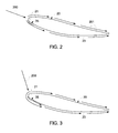
FIG. 2 is a radial view of the aerodynamic element of FIG. 1 during baseline operations;
FIG. 3 is a radial view of the aerodynamic element of FIG. 1 during part load operations;
FIG. 4 is an enlarged view of a suction side of the aerodynamic element of FIG. 1;
FIG. 5 is a radial view of the aerodynamic element of FIG. 1 in accordance with further embodiments;
FIG. 6 is a radial view of the aerodynamic element of FIG. 1 in accordance with alternative embodiments; and
FIG. 7 is a side view of a diffuser of a turbine engine including an aerodynamic element in accordance with further embodiments.
The detailed description explains embodiments of the invention, together with advantages and features, by way of example with reference to the drawings.
DETAILED DESCRIPTION OF THE INVENTION
In accordance with aspects of the invention, delayed flow separation in one or more portions of a turbomachine is provided for by the creation of counter-rotating vortex flows along, for example, a low-pressure surface (i.e., a suction side) of an airfoil or vane. The delayed flow separation is particularly useful during relatively high angle-of-attack conditions associated with turn-down operations of the turbomachine. The delayed flow separation is facilitated through the addition of contours, such as bumps, protrusions or indentations, to the low-pressure surface of the airfoil or vane that encourage tangential counter-rotating vortex flow structures to form along lines defined perpendicularly with respect to a main flow direction through the turbomachine of a working fluid.
With reference to FIGS. 1-4, one or more portions of a turbomachine 10, such as a gas turbine engine, are provided. As an example, the turbomachine 10 portion may be a diffuser section 11 (see FIG. 7), which is disposed downstream from a turbine section to reduce a remaining energy of combustion products exiting the turbine section before they are exhausted to the atmosphere. The diffuser section 11 includes an annular outer wall 12, such as a diffuser casing, and an annular inner wall 13, which may be provided as an exterior surface of a center body. The annular inner wall 13 is disposed within the annular outer wall 12 to define an annular pathway 14 through which a working fluid, such as the combustion products, may be directed (see FIG. 7).
The diffuser section 11 further includes an aerodynamic element 20, such as a diffuser vane, which is disposed to traverse the annular pathway 14 to thereby aerodynamically interact with the working fluid. The aerodynamic element 20 includes a leading edge 21 defined with respect to a predominant direction of a flow of the working fluid through the pathway 14 and a trailing edge 22 defined at an opposite chordal end of the aerodynamic element 20 from the leading edge 21. The aerodynamic element 20 further includes a suction side 23 and a pressure side 24, which are disposed on opposite sides of the aerodynamic element 20 and respectively extend from the leading edge 21 to the trailing edge 22.
In accordance with embodiments of the invention, an array of contour features 30, including individual contour features 31, is provided on the suction side 23 at a chordal location proximate to the leading edge 21 of the aerodynamic element 20. Each individual contour feature 31 is disposed relatively closely to another (i.e., adjacent) individual contour feature 31. The array of contour features 30 includes at least a first contour feature 32 and a second contour feature 33 and, in some cases, additional contour features 34. For purposes of clarity and brevity, the description below will simply describe a plurality of contour features 35 that includes the above-mentioned contour features.
Each one of the plurality of contour features 35 is substantially aligned with an adjacent one of the plurality of contour features 35 along a spanwise dimension, DS, of the aerodynamic element 20. This alignment and the shapes of the plurality of contour features 35, which will be described below, encourages the generation of tangential counter-rotating vortex flows 40 (see FIG. 4) along the suction side 23 relative to a base flow of the working fluid that proceeds along a substantially straight path through the turbomachine 10 in a main flow direction 50 (see FIG. 4). Due to the shapes of the plurality of contour features 35, the counter-rotating vortex flows 40 may be oriented substantially perpendicularly with respect to the main flow direction 50 of the working fluid. Thus, the counter-rotating vortex flows 40 combine to create an enhanced jet of entrained and energized flow 60 along the suction side 23. The entrained and energized flow 60 (see FIG. 4) maintains boundary layer stability along the suction side 23 and thereby delays or prevents flow separation from the suction side 23 in certain applications, such as those present during high angle-of-attack inlet conditions.
As shown in FIG. 4, the counter-rotating vortex flows 40 are defined on either side of each enhanced jet of entrained and energized flow 60. At various and discrete axial positions, the counter-rotating vortex flows 40 are provided as pairs of flow vortices. Within each individual flow vortex, working fluid flows toward a mid-line of the corresponding contour feature 35 and then away from the mid-line in an elliptical pattern. The pairs of flow vortices may propagate in the aft axial direction or be fixed in the discrete axial positions.
With reference to FIGS. 2 and 3, a single aerodynamic element 20 and a flow of working fluid 200 are illustrated with the assumption that the illustration is reflective of baseline or design point conditions. As shown, the flow of working fluid 200 has a relatively low angle-of-attack relative to the leading edge 21 and, therefore, the flow of working fluid 200 flows around the aerodynamic element 20 with relatively stable boundary layers 201. During part load conditions associated with, for example, turn-down operations of the turbomachine 10, the flow of working fluid 200 will tend to have a relatively high angle-of-attack, as shown in FIG. 3. Normally, this would tend to de-stabilize the boundary layers 201 and lead to flow separation but, since the suction side 23 is provided with the plurality of contour features 35, the boundary layers 201 remain relatively stable. The presence of the plurality of contour features 35 does not substantially affect the flow of working fluid 200 around the aerodynamic element 20 in the case illustrated in FIG. 2.
Each one of the plurality of contour features 35 may include a protrusion 70 disposed on the suction side 23 of the aerodynamic element 20 at a chordal location that is proximate to the leading edge 21. As shown in FIG. 4 and, in accordance with embodiments, each one of the plurality of contour features 35 may have a substantially similar teardrop shape 71 with a bulbous, convex front end 710 and a narrowed, concave tail end 711. For those cases, where each one of the plurality of contour features 35 has a substantially similar shape as another one of the plurality of contour features 35, the teardrop shape 71 causes approaching flows 72 to diverge over a surface of the protrusion 70 to thereby generate pairs of converging flows 73 between adjacent protrusions 70. With adjacent protrusions 70 being sufficiently close to one another, the pairs of converging flows 73 interact with one another and with the surrounding flows to generate the counter-rotating vortex flows 40 that propagate along the suction side 23 to thereby create the enhanced jet of entrained and energized flow 60 along the suction side 23.
While FIGS. 1-4 relate to embodiments in which each one of the plurality of contour features 35 has a similar shape, it is to be understood that this is merely exemplary and that other embodiments exist. For example, with reference to FIG. 5, the individual contour features 31 of the plurality of contour features 35 may have steadily varying shapes or sizes along the spanwise dimension, DS, of the aerodynamic element 20. This is illustrated in FIG. 5 with each dotted, dashed or solid line identifying an individual contour feature 31 having a unique size at steadily increasing, respective spanwise locations of the aerodynamic element 20.
With reference to FIG. 6 and, in accordance with alternative embodiments, each one of the plurality of contour features 35 may be formed as a depression 80 defined in the suction side 23. For these alternative embodiments, it is to be understood that the variations described above with reference to FIG. 5 apply here as well. That is, the shapes and sizes of the depressions 80 may be uniform or steadily varied along the spanwise dimension, DS, of the aerodynamic element 20.
With reference to FIG. 7, the particular case in which the turbomachine 10 portion is provided as a diffuser section 11 is shown. As noted above, the diffuser section 11 is disposed downstream from a turbine section to reduce a remaining energy of combustion products exiting the turbine section before the combustion products are exhausted to the atmosphere. The diffuser section 11 includes an annular outer wall 12, such as a diffuser casing, and an annular inner wall 13, which is provided as an exterior surface of center body 130. The annular inner wall 13 is disposed within the annular outer wall 12 to define an annular pathway 14 through which a working fluid, such as the combustion products, may be directed.
The diffuser section 11 may further include a manway 15, which traverses the annular pathway 14 and an aerodynamic element 20, which may be provided as the diffuser vane described above or at an axial end of the center body 130 as a center body end component 131. As shown in FIG. 7, the center body 130 has a substantially uniform diameter while the annular outer wall 12 has an increasing diameter along an axial dimension, DA, of the diffuser section 11. This configuration results in an area of the annular pathway 14 increasing along the axial dimension, DA, which, in turn, leads to the energy reduction of the working fluid. In contrast to the configuration of the center body 130, the center body end component 131 has a decreasing diameter along the axial dimension, DA, such that, along the axial length of the center body end component 131, the area of the annular pathway 14 increases at a relatively fast rate as compared to relatively slow increases in the area of the annular pathway 14 along an axial length of the center body 130 defined forwardly from the center body end component 131.
An angular break 90 is defined at an attachment location between the center body 130 and the center body end component 131, although it is to be understood that the center body 130 and the center body end component 131 may be integrally coupled. The angular break 90 defines an axial location at which the annular pathway 14 increases in area along the axial dimension, DA, at the relatively fast rate.
The annular inner wall 13, which is provided as the exterior surface of center body 130 and the center body end component 131, includes an array of endwall contour features 100. The array of endwall contour features 100 includes individual endwall contour features 101 and is disposed at an axial location defined proximate to the angular break 90. That is, the array of endwall contour features 100 may be disposed just forward or just aft of the angular break 90. The array of endwall contour features 100 may be configured substantially similarly as the array of contour features 30 described above and additional description of the same is therefore omitted.
While the invention has been described in detail in connection with only a limited number of embodiments, it should be readily understood that the invention is not limited to such disclosed embodiments. Rather, the invention can be modified to incorporate any number of variations, alterations, substitutions or equivalent arrangements not heretofore described, but which are commensurate with the spirit and scope of the invention. Additionally, while various embodiments of the invention have been described, it is to be understood that aspects of the invention may include only some of the described embodiments. Accordingly, the invention is not to be seen as limited by the foregoing description, but is only limited by the scope of the appended claims.

Claims (8)

The invention claimed is:
1. A turbine engine, comprising:
an aerodynamic element disposed to aerodynamically interact with a flow of working fluid; and
more than two contour features disposed on the aerodynamic element in alignment in at least one dimension,
the contour features being proximate to one another and configured to encourage counter-rotating vortex flow generation oriented substantially perpendicularly with respect to a main flow direction along the aerodynamic element,
wherein the aerodynamic element comprises an annular inner wall of a diffuser, the diffuser comprising a center body having a substantially uniform diameter and a center body end component having a decreasing diameter along an axial dimension thus defining an annular pathway, wherein, along an axial length of the center body end component, an area of an annular pathway increases at a relatively fast rate as compared to relatively slow increases in the area of the annular pathway along an axial length of the center body defined forwardly from the center body end component;
and the contour features each have a same teardrop shape, are all oriented in parallel with one another and are aligned at an angular break defined along the annular inner wall, wherein each teardrop shaped contour feature comprises a bulbous front end and a narrowed tail end; and
wherein the bulbous front end has a convex shape and the narrowed tail end has a concave shape and thereby causes approaching flows to diverge over a surface of the protrusion to thereby generate pairs of converging flows between adjacent protrusions.
2. The turbine engine according to claim 1, wherein each of the contour features comprises a protrusion.
3. The turbine engine according to claim 1, wherein each of the contour features comprises a depression.
4. An aerodynamic element of a turbine engine, comprising:
an annular inner diffuser wall disposed within an annular outer wall to define an annular pathway,
the annular inner diffuser wall including an angular break defining an axial location at which the annular pathway increases in area at a faster rate along an axial dimension aft of the angular break than along an axial dimension forward from the angular break; and
more than two contour features disposed on the annular inner diffuser wall,
the diffuser comprising a center body having a substantially uniform diameter and a center body end component having a decreasing diameter along an axial dimension thus defining an annular pathway, wherein, along an axial length of the center body end component, an area of an annular pathway increases at a relatively fast rate as compared to relatively slow increases in the area of the annular pathway along an axial length of the center body defined forwardly from the center body end component; and
each of the more than two contour features having a same teardrop shape, being all oriented in parallel with one another and being proximate to the angular break and substantially aligned along the axial location, wherein each teardrop shaped contour feature comprises a bulbous front end and a narrowed tail end; and
wherein the bulbous front end has a convex shape and the narrowed tail end has a concave shape and thereby causes approaching flows to diverge over a surface of the protrusion to thereby generate pairs of converging flows between adjacent protrusions.
5. The aerodynamic element of the turbine engine according to claim 4, wherein each of the more than two contour features comprises one of a protrusion or a depression.
6. The aerodynamic element of the turbine engine according to claim 4, wherein each of the more than two contour features have substantially similar shapes.
7. An aerodynamic element of a turbine engine, comprising:
an annular inner diffuser wall disposed within an annular outer wall to define an annular pathway,
the annular inner diffuser wall including an angular break defining an axial location at which the annular pathway increases in area at a faster rate along an axial dimension aft of the angular break than along an axial dimension forward from the angular break; and
more than two contour features arrayed on the annular inner diffuser wall, each of the contour features having a same teardrop shape, being all oriented in parallel with one another and being proximate to the angular break and an adjacent contour feature,
the diffuser comprising a center body having a substantially uniform diameter and a center body end component having a decreasing diameter along an axial dimension thus defining an annular pathway, wherein, along an axial length of the center body end component, an area of an annular pathway increases at a relatively fast rate as compared to relatively slow increases in the area of the annular pathway along an axial length of the center body defined forwardly from the center body end component, and
each of the contour features being substantially aligned along the axial location to encourage a generation of counter-rotating vortex flows oriented substantially perpendicularly with respect to a main flow direction along the annular inner diffuser wall,
wherein each teardrop shaped contour feature comprises a bulbous front end and a narrowed tail end; and wherein the bulbous front end has a convex shape and the narrowed tail end has a concave shape.
8. The aerodynamic element of the turbine engine according to claim 7, wherein each of the contour features comprises one of a protrusion or a depression.
US13/492,485 2012-06-08 2012-06-08 Turbine engine and aerodynamic element of turbine engine Active 2034-04-09 US9488055B2 (en)

Priority Applications (5)

Application Number Priority Date Filing Date Title
US13/492,485 US9488055B2 (en) 2012-06-08 2012-06-08 Turbine engine and aerodynamic element of turbine engine
JP2013119357A JP6262944B2 (en) 2012-06-08 2013-06-06 Turbine engine and aerodynamic element of turbine engine
EP13170779.6A EP2672064B1 (en) 2012-06-08 2013-06-06 Turbine engine and aerodynamic element of turbine engine
RU2013126230/06A RU2013126230A (en) 2012-06-08 2013-06-07 GAS-TURBINE ENGINE AND AERODYNAMIC ELEMENT OF A GAS-TURBINE ENGINE
CN201310224780.3A CN103485846B (en) 2012-06-08 2013-06-07 Turbogenerator and the Pneumatic assembly of turbogenerator

Applications Claiming Priority (1)

Application Number Priority Date Filing Date Title
US13/492,485 US9488055B2 (en) 2012-06-08 2012-06-08 Turbine engine and aerodynamic element of turbine engine

Publications (2)

Publication Number Publication Date
US20130330183A1 US20130330183A1 (en) 2013-12-12
US9488055B2 true US9488055B2 (en) 2016-11-08

Family

ID=48576825

Family Applications (1)

Application Number Title Priority Date Filing Date
US13/492,485 Active 2034-04-09 US9488055B2 (en) 2012-06-08 2012-06-08 Turbine engine and aerodynamic element of turbine engine

Country Status (5)

Country Link
US (1) US9488055B2 (en)
EP (1) EP2672064B1 (en)
JP (1) JP6262944B2 (en)
CN (1) CN103485846B (en)
RU (1) RU2013126230A (en)

Cited By (1)

* Cited by examiner, † Cited by third party
Publication number Priority date Publication date Assignee Title
CN112092927A (en) * 2020-10-22 2020-12-18 河北工业大学 Vortex generator based on FSAE racing car

Families Citing this family (5)

* Cited by examiner, † Cited by third party
Publication number Priority date Publication date Assignee Title
US10151325B2 (en) * 2015-04-08 2018-12-11 General Electric Company Gas turbine diffuser strut including a trailing edge flap and methods of assembling the same
WO2018124068A1 (en) * 2016-12-26 2018-07-05 三菱重工業株式会社 Turbine and gas turbine
JP6820735B2 (en) * 2016-12-26 2021-01-27 三菱重工業株式会社 Turbines and gas turbines
US10808540B2 (en) 2018-03-22 2020-10-20 Raytheon Technologies Corporation Case for gas turbine engine
JP7250438B2 (en) * 2018-05-25 2023-04-03 三菱重工サーマルシステムズ株式会社 air conditioner

Citations (24)

* Cited by examiner, † Cited by third party
Publication number Priority date Publication date Assignee Title
US3012709A (en) * 1955-05-18 1961-12-12 Daimler Benz Ag Blade for axial compressors
US4023550A (en) 1974-08-27 1977-05-17 Briggs & Stratton Corporation Engine with overspeed prevention
US4431374A (en) 1981-02-23 1984-02-14 Teledyne Industries, Inc. Vortex controlled radial diffuser for centrifugal compressor
US5099685A (en) * 1990-08-09 1992-03-31 The Boeing Company Boundary layer control diffuser for a wind tunnel or the like
US5927939A (en) 1994-12-28 1999-07-27 Ebara Corporation Turbomachine having variable angle flow guiding device
US6099248A (en) 1997-11-17 2000-08-08 Abb Alstom Power (Switzerland) Ltd Output stage for an axial-flow turbine
US6139258A (en) 1987-03-30 2000-10-31 United Technologies Corporation Airfoils with leading edge pockets for reduced heat transfer
US6431498B1 (en) 2000-06-30 2002-08-13 Philip Watts Scalloped wing leading edge
US6547524B2 (en) 2001-05-21 2003-04-15 United Technologies Corporation Film cooled article with improved temperature tolerance
US20040104309A1 (en) 2002-06-21 2004-06-03 Darko Segota Method and system for regulating external fluid flow over an object's surface, and particularly a wing and diffuser
DE102006038060A1 (en) 2006-08-16 2008-02-21 Hoffer, Otto, Dipl.-Ing. Blade for turbo machine, comprises current stumbling element, where current is applied along prospective detachment position transversely to required number of current stumbling elements
US20080121301A1 (en) * 2004-04-09 2008-05-29 Norris Thomas R Externally Mounted Vortex Generators for Flow Duct Passage
US7484937B2 (en) 2004-06-02 2009-02-03 Rolls-Royce Deutschland Ltd & Co Kg Compressor blade with reduced aerodynamic blade excitation
US20090074578A1 (en) 2004-10-18 2009-03-19 Whale-Power Corporation Turbine and compressor employing tubercle leading edge rotor design
US7614588B2 (en) * 2004-12-23 2009-11-10 David Birkenstock Apparatus system and method for drag reduction
US7914259B2 (en) 2007-03-20 2011-03-29 Vestas Wind Systems A/S Wind turbine blades with vortex generators
WO2011077424A1 (en) 2009-12-21 2011-06-30 Ramot At Tel-Aviv University Ltd. Oscillatory vorticity generator and applications thereof
US20110182746A1 (en) 2008-07-19 2011-07-28 Mtu Aero Engines Gmbh Blade for a turbo device with a vortex-generator
US20110229321A1 (en) 2008-12-02 2011-09-22 Aerovortex Mills Ltd Vortex dynamics turbine
EP2369133A1 (en) 2010-03-22 2011-09-28 Rolls-Royce Deutschland Ltd & Co KG Airfoil for a turbo-machine
US8061989B1 (en) 2008-10-20 2011-11-22 Florida Turbine Technologies, Inc. Turbine blade with near wall cooling
US8070454B1 (en) 2007-12-12 2011-12-06 Florida Turbine Technologies, Inc. Turbine airfoil with trailing edge
US8100643B2 (en) 2009-04-30 2012-01-24 Pratt & Whitney Canada Corp. Centrifugal compressor vane diffuser wall contouring
US20120018021A1 (en) 2009-09-30 2012-01-26 The Board Of Trustees Of The University Of Illinois Vortex generators to control boundary layer interactions

Family Cites Families (5)

* Cited by examiner, † Cited by third party
Publication number Priority date Publication date Assignee Title
FR1104644A (en) * 1954-02-15 1955-11-22 Thomson Houston Comp Francaise Improvements to Fluid Flow Control Systems
US4023350A (en) * 1975-11-10 1977-05-17 United Technologies Corporation Exhaust case for a turbine machine
JP4161201B2 (en) * 2003-05-23 2008-10-08 三菱自動車工業株式会社 Air resistance reduction device for automobiles
JP5550319B2 (en) * 2009-12-10 2014-07-16 三菱重工業株式会社 Multiblade centrifugal fan and air conditioner using the same
JP5449087B2 (en) * 2010-08-12 2014-03-19 三菱重工業株式会社 Wing

Patent Citations (25)

* Cited by examiner, † Cited by third party
Publication number Priority date Publication date Assignee Title
US3012709A (en) * 1955-05-18 1961-12-12 Daimler Benz Ag Blade for axial compressors
US4023550A (en) 1974-08-27 1977-05-17 Briggs & Stratton Corporation Engine with overspeed prevention
US4431374A (en) 1981-02-23 1984-02-14 Teledyne Industries, Inc. Vortex controlled radial diffuser for centrifugal compressor
US6139258A (en) 1987-03-30 2000-10-31 United Technologies Corporation Airfoils with leading edge pockets for reduced heat transfer
US5099685A (en) * 1990-08-09 1992-03-31 The Boeing Company Boundary layer control diffuser for a wind tunnel or the like
US5927939A (en) 1994-12-28 1999-07-27 Ebara Corporation Turbomachine having variable angle flow guiding device
US6099248A (en) 1997-11-17 2000-08-08 Abb Alstom Power (Switzerland) Ltd Output stage for an axial-flow turbine
US6431498B1 (en) 2000-06-30 2002-08-13 Philip Watts Scalloped wing leading edge
US6547524B2 (en) 2001-05-21 2003-04-15 United Technologies Corporation Film cooled article with improved temperature tolerance
US7475853B2 (en) 2002-06-21 2009-01-13 Darko Segota Method and system for regulating external fluid flow over an object's surface, and particularly a wing and diffuser
US20040104309A1 (en) 2002-06-21 2004-06-03 Darko Segota Method and system for regulating external fluid flow over an object's surface, and particularly a wing and diffuser
US20080121301A1 (en) * 2004-04-09 2008-05-29 Norris Thomas R Externally Mounted Vortex Generators for Flow Duct Passage
US7484937B2 (en) 2004-06-02 2009-02-03 Rolls-Royce Deutschland Ltd & Co Kg Compressor blade with reduced aerodynamic blade excitation
US20090074578A1 (en) 2004-10-18 2009-03-19 Whale-Power Corporation Turbine and compressor employing tubercle leading edge rotor design
US7614588B2 (en) * 2004-12-23 2009-11-10 David Birkenstock Apparatus system and method for drag reduction
DE102006038060A1 (en) 2006-08-16 2008-02-21 Hoffer, Otto, Dipl.-Ing. Blade for turbo machine, comprises current stumbling element, where current is applied along prospective detachment position transversely to required number of current stumbling elements
US7914259B2 (en) 2007-03-20 2011-03-29 Vestas Wind Systems A/S Wind turbine blades with vortex generators
US8070454B1 (en) 2007-12-12 2011-12-06 Florida Turbine Technologies, Inc. Turbine airfoil with trailing edge
US20110182746A1 (en) 2008-07-19 2011-07-28 Mtu Aero Engines Gmbh Blade for a turbo device with a vortex-generator
US8061989B1 (en) 2008-10-20 2011-11-22 Florida Turbine Technologies, Inc. Turbine blade with near wall cooling
US20110229321A1 (en) 2008-12-02 2011-09-22 Aerovortex Mills Ltd Vortex dynamics turbine
US8100643B2 (en) 2009-04-30 2012-01-24 Pratt & Whitney Canada Corp. Centrifugal compressor vane diffuser wall contouring
US20120018021A1 (en) 2009-09-30 2012-01-26 The Board Of Trustees Of The University Of Illinois Vortex generators to control boundary layer interactions
WO2011077424A1 (en) 2009-12-21 2011-06-30 Ramot At Tel-Aviv University Ltd. Oscillatory vorticity generator and applications thereof
EP2369133A1 (en) 2010-03-22 2011-09-28 Rolls-Royce Deutschland Ltd & Co KG Airfoil for a turbo-machine

Non-Patent Citations (1)

* Cited by examiner, † Cited by third party
Title
Search Report from EP Application No. 13170779.6 dated Sep. 12, 2013.

Cited By (1)

* Cited by examiner, † Cited by third party
Publication number Priority date Publication date Assignee Title
CN112092927A (en) * 2020-10-22 2020-12-18 河北工业大学 Vortex generator based on FSAE racing car

Also Published As

Publication number Publication date
CN103485846A (en) 2014-01-01
JP2013257137A (en) 2013-12-26
JP6262944B2 (en) 2018-01-17
RU2013126230A (en) 2014-12-20
US20130330183A1 (en) 2013-12-12
EP2672064A1 (en) 2013-12-11
EP2672064B1 (en) 2017-08-30
CN103485846B (en) 2017-03-01

Similar Documents

Publication Publication Date Title
US9488055B2 (en) Turbine engine and aerodynamic element of turbine engine
JP6025269B2 (en) Compressor airfoil with tip angle
JP6060145B2 (en) High camber compressor rotor blade
EP2631491B1 (en) Transonic blade
US7753652B2 (en) Aero-mixing of rotating blade structures
JP5300874B2 (en) Blade with non-axisymmetric platform and depression and protrusion on outer ring
US9957973B2 (en) Blade with an S-shaped profile for an axial turbomachine compressor
US10329923B2 (en) Gas turbine engine airfoil leading edge cooling
JP2017528632A (en) Endwall configuration for gas turbine engines
US20060275134A1 (en) Blade of axial flow-type rotary fluid machine
JP2008157247A (en) Turbine assembly of gas turbine engine and its manufacturing method
US20120315136A1 (en) Inner peripheral surface shape of casing of axial-flow compressor
US10060441B2 (en) Gas turbine stator with winglets
JP6173489B2 (en) Gas turbine engine with ambient air cooling system with pre-turning vanes
US20160177728A1 (en) Vane structure for axial flow turbomachine and gas turbine engine
US11175042B2 (en) Combustion equipment
JP2015081601A (en) Gas turbine nozzle trailing edge fillet
JP6624653B2 (en) Press whirl system for gas turbine
US11708762B2 (en) Film cooling structure and turbine blade for gas turbine engine
EP2672080A2 (en) Aerodynamic Element of Turbine Engine
JP2013096408A (en) Airfoil part and method of manufacturing the same
JP2020133602A (en) Blade and machine with the same
US11732591B2 (en) Film cooling structure and turbine blade for gas turbine engine
EP3334904B1 (en) Diffuser for a turbine engine and method of forming same
CN113464209A (en) Turbine rotor blade having cooling circuit with offset ribs

Legal Events

Date Code Title Description
AS Assignment

Owner name: GENERAL ELECTRIC COMPANY, NEW YORK

Free format text: ASSIGNMENT OF ASSIGNORS INTEREST;ASSIGNOR:SPARKS, SCOTT MATTHEW;REEL/FRAME:028347/0022

Effective date: 20120608

STCF Information on status: patent grant

Free format text: PATENTED CASE

MAFP Maintenance fee payment

Free format text: PAYMENT OF MAINTENANCE FEE, 4TH YEAR, LARGE ENTITY (ORIGINAL EVENT CODE: M1551); ENTITY STATUS OF PATENT OWNER: LARGE ENTITY

Year of fee payment: 4

AS Assignment

Owner name: GE INFRASTRUCTURE TECHNOLOGY LLC, SOUTH CAROLINA

Free format text: ASSIGNMENT OF ASSIGNORS INTEREST;ASSIGNOR:GENERAL ELECTRIC COMPANY;REEL/FRAME:065727/0001

Effective date: 20231110