US9482096B1 - Textured leading edge for aerospace and nautical structures - Google Patents
Textured leading edge for aerospace and nautical structures Download PDFInfo
- Publication number
- US9482096B1 US9482096B1 US14/698,334 US201514698334A US9482096B1 US 9482096 B1 US9482096 B1 US 9482096B1 US 201514698334 A US201514698334 A US 201514698334A US 9482096 B1 US9482096 B1 US 9482096B1
- Authority
- US
- United States
- Prior art keywords
- grooves
- surface area
- fluid
- flow direction
- groove
- Prior art date
- Legal status (The legal status is an assumption and is not a legal conclusion. Google has not performed a legal analysis and makes no representation as to the accuracy of the status listed.)
- Active, expires
Links
Images


Classifications
-
- B—PERFORMING OPERATIONS; TRANSPORTING
- B63—SHIPS OR OTHER WATERBORNE VESSELS; RELATED EQUIPMENT
- B63B—SHIPS OR OTHER WATERBORNE VESSELS; EQUIPMENT FOR SHIPPING
- B63B1/00—Hydrodynamic or hydrostatic features of hulls or of hydrofoils
- B63B1/32—Other means for varying the inherent hydrodynamic characteristics of hulls
- B63B1/34—Other means for varying the inherent hydrodynamic characteristics of hulls by reducing surface friction
- B63B1/36—Other means for varying the inherent hydrodynamic characteristics of hulls by reducing surface friction using mechanical means
-
- F—MECHANICAL ENGINEERING; LIGHTING; HEATING; WEAPONS; BLASTING
- F01—MACHINES OR ENGINES IN GENERAL; ENGINE PLANTS IN GENERAL; STEAM ENGINES
- F01D—NON-POSITIVE DISPLACEMENT MACHINES OR ENGINES, e.g. STEAM TURBINES
- F01D5/00—Blades; Blade-carrying members; Heating, heat-insulating, cooling or antivibration means on the blades or the members
- F01D5/12—Blades
- F01D5/14—Form or construction
- F01D5/141—Shape, i.e. outer, aerodynamic form
-
- B—PERFORMING OPERATIONS; TRANSPORTING
- B63—SHIPS OR OTHER WATERBORNE VESSELS; RELATED EQUIPMENT
- B63B—SHIPS OR OTHER WATERBORNE VESSELS; EQUIPMENT FOR SHIPPING
- B63B1/00—Hydrodynamic or hydrostatic features of hulls or of hydrofoils
- B63B1/02—Hydrodynamic or hydrostatic features of hulls or of hydrofoils deriving lift mainly from water displacement
- B63B1/04—Hydrodynamic or hydrostatic features of hulls or of hydrofoils deriving lift mainly from water displacement with single hull
- B63B1/06—Shape of fore part
-
- B—PERFORMING OPERATIONS; TRANSPORTING
- B63—SHIPS OR OTHER WATERBORNE VESSELS; RELATED EQUIPMENT
- B63H—MARINE PROPULSION OR STEERING
- B63H25/00—Steering; Slowing-down otherwise than by use of propulsive elements; Dynamic anchoring, i.e. positioning vessels by means of main or auxiliary propulsive elements
- B63H25/06—Steering by rudders
- B63H25/38—Rudders
-
- B—PERFORMING OPERATIONS; TRANSPORTING
- B64—AIRCRAFT; AVIATION; COSMONAUTICS
- B64C—AEROPLANES; HELICOPTERS
- B64C3/00—Wings
- B64C3/26—Construction, shape, or attachment of separate skins, e.g. panels
-
- F—MECHANICAL ENGINEERING; LIGHTING; HEATING; WEAPONS; BLASTING
- F15—FLUID-PRESSURE ACTUATORS; HYDRAULICS OR PNEUMATICS IN GENERAL
- F15D—FLUID DYNAMICS, i.e. METHODS OR MEANS FOR INFLUENCING THE FLOW OF GASES OR LIQUIDS
- F15D1/00—Influencing flow of fluids
- F15D1/002—Influencing flow of fluids by influencing the boundary layer
- F15D1/0025—Influencing flow of fluids by influencing the boundary layer using passive means, i.e. without external energy supply
- F15D1/003—Influencing flow of fluids by influencing the boundary layer using passive means, i.e. without external energy supply comprising surface features, e.g. indentations or protrusions
- F15D1/005—Influencing flow of fluids by influencing the boundary layer using passive means, i.e. without external energy supply comprising surface features, e.g. indentations or protrusions in the form of dimples
-
- B—PERFORMING OPERATIONS; TRANSPORTING
- B64—AIRCRAFT; AVIATION; COSMONAUTICS
- B64C—AEROPLANES; HELICOPTERS
- B64C2230/00—Boundary layer controls
- B64C2230/22—Boundary layer controls by using a surface having multiple apertures of relatively small openings other than slots
-
- F—MECHANICAL ENGINEERING; LIGHTING; HEATING; WEAPONS; BLASTING
- F05—INDEXING SCHEMES RELATING TO ENGINES OR PUMPS IN VARIOUS SUBCLASSES OF CLASSES F01-F04
- F05D—INDEXING SCHEME FOR ASPECTS RELATING TO NON-POSITIVE-DISPLACEMENT MACHINES OR ENGINES, GAS-TURBINES OR JET-PROPULSION PLANTS
- F05D2220/00—Application
- F05D2220/30—Application in turbines
- F05D2220/32—Application in turbines in gas turbines
- F05D2220/323—Application in turbines in gas turbines for aircraft propulsion, e.g. jet engines
-
- F—MECHANICAL ENGINEERING; LIGHTING; HEATING; WEAPONS; BLASTING
- F05—INDEXING SCHEMES RELATING TO ENGINES OR PUMPS IN VARIOUS SUBCLASSES OF CLASSES F01-F04
- F05D—INDEXING SCHEME FOR ASPECTS RELATING TO NON-POSITIVE-DISPLACEMENT MACHINES OR ENGINES, GAS-TURBINES OR JET-PROPULSION PLANTS
- F05D2220/00—Application
- F05D2220/30—Application in turbines
- F05D2220/36—Application in turbines specially adapted for the fan of turbofan engines
-
- F—MECHANICAL ENGINEERING; LIGHTING; HEATING; WEAPONS; BLASTING
- F05—INDEXING SCHEMES RELATING TO ENGINES OR PUMPS IN VARIOUS SUBCLASSES OF CLASSES F01-F04
- F05D—INDEXING SCHEME FOR ASPECTS RELATING TO NON-POSITIVE-DISPLACEMENT MACHINES OR ENGINES, GAS-TURBINES OR JET-PROPULSION PLANTS
- F05D2240/00—Components
- F05D2240/20—Rotors
- F05D2240/30—Characteristics of rotor blades, i.e. of any element transforming dynamic fluid energy to or from rotational energy and being attached to a rotor
-
- F—MECHANICAL ENGINEERING; LIGHTING; HEATING; WEAPONS; BLASTING
- F05—INDEXING SCHEMES RELATING TO ENGINES OR PUMPS IN VARIOUS SUBCLASSES OF CLASSES F01-F04
- F05D—INDEXING SCHEME FOR ASPECTS RELATING TO NON-POSITIVE-DISPLACEMENT MACHINES OR ENGINES, GAS-TURBINES OR JET-PROPULSION PLANTS
- F05D2250/00—Geometry
- F05D2250/60—Structure; Surface texture
- F05D2250/63—Structure; Surface texture coarse
-
- Y—GENERAL TAGGING OF NEW TECHNOLOGICAL DEVELOPMENTS; GENERAL TAGGING OF CROSS-SECTIONAL TECHNOLOGIES SPANNING OVER SEVERAL SECTIONS OF THE IPC; TECHNICAL SUBJECTS COVERED BY FORMER USPC CROSS-REFERENCE ART COLLECTIONS [XRACs] AND DIGESTS
- Y02—TECHNOLOGIES OR APPLICATIONS FOR MITIGATION OR ADAPTATION AGAINST CLIMATE CHANGE
- Y02T—CLIMATE CHANGE MITIGATION TECHNOLOGIES RELATED TO TRANSPORTATION
- Y02T50/00—Aeronautics or air transport
- Y02T50/10—Drag reduction
-
- Y—GENERAL TAGGING OF NEW TECHNOLOGICAL DEVELOPMENTS; GENERAL TAGGING OF CROSS-SECTIONAL TECHNOLOGIES SPANNING OVER SEVERAL SECTIONS OF THE IPC; TECHNICAL SUBJECTS COVERED BY FORMER USPC CROSS-REFERENCE ART COLLECTIONS [XRACs] AND DIGESTS
- Y02—TECHNOLOGIES OR APPLICATIONS FOR MITIGATION OR ADAPTATION AGAINST CLIMATE CHANGE
- Y02T—CLIMATE CHANGE MITIGATION TECHNOLOGIES RELATED TO TRANSPORTATION
- Y02T70/00—Maritime or waterways transport
- Y02T70/10—Measures concerning design or construction of watercraft hulls
Definitions
- This disclosure pertains to a surface area of a structure that has been fabricated with a textured surface that reduces the surface wear rate or erosion caused by a high speed flow of fluid containing abrasive particles over the surface area.
- fluid what is meant is a liquid, a gas or a combination thereof.
- this disclosure pertains to a leading edge surface such as a rotor leading edge surface, an aircraft airfoil leading edge surface, a propeller leading edge surface, etc. that is fabricated with a textured surface comprised of a plurality of grooves that alter or break up a high speed flow of fluid containing abrasive particles over the textured surface. The grooves are contacted by the high speed flow of fluid containing the abrasive particles and alter or break up the flow of fluid and abrasive particles and thereby reduce surface wear rate or erosion of the structure leading edge.
- leading edges of these structures experience a surface wear rate or erosion as the leading edges are moved at a high speed through fluid such as air or water during operation of the structures. This is particularly true where the leading edges of the structures are moved at high speed through a fluid containing airborne or waterborne abrasive particles, such as sand in the air or water.
- the textured surface of this disclosure is designed to minimize the erosion that sand or other airborne or waterborne abrasive particles moving at high speed, or gases moving at high speed cause on the leading edge surfaces of structures such as aircraft rotor blades, aircraft airfoil surfaces on wings, wind turbine blades, marine propellers and rudders, and other such similar structures.
- the textured surface can be formed into a surface area of a leading edge of a structure, or applied to the surface area of the leading edge of the structure.
- the textured surface is characterized by a plurality of grooves that are recessed into the surface area or formed on the surface area of the leading edge surface of the structure.
- the plurality of grooves can have a variety of shapes and combinations of shapes.
- the shapes may have a range of different orientations with respect to the leading edge area of the structure and the direction of fluid flow over the leading edge surface. Spacings between the plurality of grooves may also be varied to suit the modified leading edge surface to conditions it will encounter.
- the plurality of grooves are positioned on or near the leading edge surface area of the structure that moves at a high speed through a fluid flow containing abrasive particles in operation of the structure.
- the grooves on the leading edge surface area alter or break up the flow direction of the fluid contacting the grooves and alter or break up the flow direction of the abrasive particles contacting the grooves.
- the altered fluid flow direction and altered particle flow direction reduces surface wear rate or erosion of the structure leading edge region.
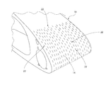
- FIG. 1 is a representation of a perspective view of a textured surface on a leading edge surface of a structure.
- FIG. 2 is a representation of a side cross-section view of the textured surface on a leading edge surface of a structure.
- FIG. 3 is a representation of a plan view of a textured surface on a surface area of a structure.
- FIG. 4 is a representation of a cross-section view of a textured surface on a surface area of a structure.
- FIG. 5 is a representation of a cross-section view of a textured surface on a surface area of a structure.
- FIG. 6 is a representation of a cross-section view of a textured surface on a surface area of a structure.
- FIG. 1 is a perspective view of a cross-section of a portion of a structure fabricated with a textured surface of this disclosure.
- the structure 10 is a portion of a propeller rotor blade.
- the textured surface is not limited to use on only rotor blade surfaces.
- a textured surface can be fabricated on structures such as aircraft rotor blades, aircraft airfoil surfaces on wings, wind turbine blades, marine propellers and rudders, and other such similar structures having a leading edge surface area that experiences a surface wear rate or erosion as the leading edge surface area is moved at high speed through a fluid such as air or water during operation of the structure.
- a helicopter rotor blade or an airplane propeller could be moving through air at least 713 km/h
- a jet engine turbine blade could be moving through air at least 2655 km/h
- a ship bow could be moving through water at least 26 knots (48 km/h).
- FIG. 2 is a representation of a cross-section view of the structure 10 of FIG. 1 .
- a textured surface is applied to a first surface area 14 on the leading edge of the structure.
- the leading edge has a u-shaped cross-section.
- the textured surface could be used on a surface area of a leading edge surface having other cross-section configurations such as triangular, semicircular, etc.
- first surface area 14 of the structure is the surface area that passes at high speed through a fluid where the fluid could contain abrasive particles such as sand, it is only necessary that the first surface area 14 be fabricated with the textured surface of this disclosure.
- a second surface area 16 and a third surface area 18 of the structure 10 that are adjacent the first surface area 14 are not directly contacted by the high speed fluid or the particles in the high speed fluid during operation of the structure.
- the second surface area 16 and the third surface area 18 be fabricated with the textured surface, its use in these areas will be dictated by operating conditions encountered in the specific application.
- the textured surface of the first surface area 14 is characterized by a plurality of grooves 22 .
- the grooves 22 can be recessed into the material of the first surface area 14 .
- the plurality of grooves 22 can have a variety of different configurations. As represented in FIG. 3 , the grooves 22 have oblong configurations with straight, parallel side edges and rounded end edges. The grooves are formed in the first surface area 14 of the structure 10 with each groove having a length dimension between a first end edge 24 and a second end edge 26 of the groove, a width dimension between a first side edge 28 and an opposite second side edge 30 of the groove, and a depth dimension between a top opening 32 of the groove and a bottom surface 34 of the groove.
- the grooves 22 represented in FIG. 3 are arranged end to end and side by side with respect to the direction of fluid flow over the leading edge first surface area 14 represented by the arrow 36 . As represented in FIG.
- the plurality of grooves 22 are arranged with the length dimensions of the plurality of grooves 22 aligned with the flow direction of fluid 36 over the first surface area 14 and with first end edges 24 of some immediately adjacent grooves 22 being spaced in the flow direction 36 from each other and with second end edges 26 of the immediately adjacent grooves 22 being spaced in the flow direction 36 from each other.
- the grooves 22 could have a range of different orientations with respect to the direction of fluid flow.
- the configurations of the grooves, the orientations of the grooves, the spacings between adjacent grooves 22 , etc. may be varied to suit the modified leading edge first surface area 14 to conditions it will encounter in use of the structure 10 .
- the grooves 22 can have a variety of different cross-section configurations across their length dimensions.
- the cross-section configurations could be rectangular or square 40 as represented in FIG. 4 , circular as semicircular 42 as represented in FIG. 5 , elliptical or parabolic 44 as represented in FIG. 6 , etc.
- the particular cross-section configuration of the grooves 22 will depend on the specific structure having the textured surface on its leading edge surface, and the service conditions in which the structure will be used.
- the plurality of grooves 22 could have variations in width to depth aspect ratio in order to minimize the abrasive wear on the leading edge surface 14 .
- the cross-section configurations of the grooves should not be limited to only the configurations shown in the drawing figures.
- An example of the dimensions of a groove 22 such as the square cross-section groove 40 represented in FIG. 4 include a depth between the top opening 32 and the bottom surface 34 of one millimeter, a width between the first side edge 28 and the second side edge 30 of one millimeter, and a length dimension between the first end edge 24 as shown in FIG. 3 and the second end edge 26 as shown in FIG. 3 of two millimeters.
- the plurality of grooves 22 are positioned on the leading edge first surface area 14 of the structure 10 that moves at a high speed through a fluid flow containing abrasive particles in operation of the structure 10 .
- the grooves 22 on the first surface area 14 alter or break up the flow direction of the fluid contacting the grooves 22 and alter or break up the flow direction of the abrasive particles contacting the grooves 22 without adding weight to the structure.
- the altered fluid flow direction and altered particle flow direction reduces the surface wear rate or erosion of the first surface area 14 of the structure 10 .
- the erosion rate can be reduced by up to 50%.
- the grooves 22 increase the service life of the structure 10 with no performance penalty, potentially doubling the service life.
- the grooves 22 of the textured first surface area 14 could be constructed or recessed into the material of the leading edge surface of the structure 10 by traditional manufacturing methods, such as laser etching, machining, chemical milling, etc. This would particularly be the case where the plurality of grooves 22 are being formed into the leading edge first surface area 14 of a structure that would be discarded when the textured first surface area 14 has worn out and the structure has lost its service performance.
- the grooves 22 of the textured surface 14 could be formed in a temporary layer that is applied to the leading first surface area 14 of the structure 10 .
- the temporary layer is not a permanent part of the structure 10 , but is removed from the structure 10 when worn out and replaced with a new temporary layer having the grooves 22 of the textured first surface area 14 . This would particularly be the case where the temporary layer could be manufactured less expensively than discarding and replacing the structure 10 when the textured first surface area 14 has worn out.
- the temporary layer having the grooves 22 of the textured surface 14 could be secured to the leading edge first surface area 14 of the structure 10 by fasteners, screws, adhesives, snap fit connections, welding or other equivalent methods.
- grooves 22 of the textured first surface area 14 could be formed into metallic material, plastics, rubbers, ceramics, composites, and a combination of these.
- the grooves 22 of the textured first surface area 14 have worn out, the grooves 22 could be renewed in place on the textured first surface area 14 by the traditional manufacturing methods mentioned earlier.
- Additional manufacturing methods such as 3D printing and other fabrication methods classified as “additive manufacturing” could be used to construct the grooves 22 on the textured first surface area 14 .
- additive manufacturing methods are characterized by the grooves 22 of the textured first surface area 14 of the structure 10 being made starting with a 3D drawing electronic file, which is converted into a set of very thin layers, which are then deposited one by one and bonded all together in one cohesive object in constructing the textured first surface area 14 of the structure 10 .
- 3D printing and any other of the above listed methods may be used to rebuild the textured first surface area 14 of the structure 10 when the first surface area 14 is worn out, without remaking the entire structure 10 . This would achieve further cost savings.
Abstract
Description
Claims (27)
Priority Applications (2)
| Application Number | Priority Date | Filing Date | Title |
|---|---|---|---|
| US14/698,334 US9482096B1 (en) | 2015-04-28 | 2015-04-28 | Textured leading edge for aerospace and nautical structures |
| EP16153900.2A EP3088290B1 (en) | 2015-04-28 | 2016-02-02 | A textured leading edge for aerospace and nautical structures |
Applications Claiming Priority (1)
| Application Number | Priority Date | Filing Date | Title |
|---|---|---|---|
| US14/698,334 US9482096B1 (en) | 2015-04-28 | 2015-04-28 | Textured leading edge for aerospace and nautical structures |
Publications (2)
| Publication Number | Publication Date |
|---|---|
| US9482096B1 true US9482096B1 (en) | 2016-11-01 |
| US20160319668A1 US20160319668A1 (en) | 2016-11-03 |
Family
ID=55315321
Family Applications (1)
| Application Number | Title | Priority Date | Filing Date |
|---|---|---|---|
| US14/698,334 Active 2035-06-05 US9482096B1 (en) | 2015-04-28 | 2015-04-28 | Textured leading edge for aerospace and nautical structures |
Country Status (2)
| Country | Link |
|---|---|
| US (1) | US9482096B1 (en) |
| EP (1) | EP3088290B1 (en) |
Cited By (4)
| Publication number | Priority date | Publication date | Assignee | Title |
|---|---|---|---|---|
| US10377464B2 (en) * | 2016-03-14 | 2019-08-13 | Airbus Operations, S.L. | Method, injection moulding tool for manufacturing a leading edge section with hybrid laminar flow control for an aircraft, and leading edge section with hybrid laminar flow control obtained thereof |
| US20190292915A1 (en) * | 2018-03-22 | 2019-09-26 | United Technologies Corporation | Case for gas turbine engine |
| US20220154744A1 (en) * | 2020-11-17 | 2022-05-19 | Subaru Corporation | Vehicle including embossed surface for improving aerodynamic characteristics, and front bumper member |
| US11614106B2 (en) | 2019-08-21 | 2023-03-28 | Lockheed Martin Corporation | Partially submerged periodic riblets |
Families Citing this family (5)
| Publication number | Priority date | Publication date | Assignee | Title |
|---|---|---|---|---|
| EP3489128A1 (en) * | 2017-11-28 | 2019-05-29 | Becker Marine Systems GmbH | Blade of an oar with modular structure, segment for a blade of an oar for a device for improving propulsion and method for producing a blade of an oar |
| US11719440B2 (en) * | 2018-12-19 | 2023-08-08 | Doosan Enerbility Co., Ltd. | Pre-swirler having dimples |
| GB2602354A (en) * | 2020-12-24 | 2022-06-29 | Thales Holdings Uk Plc | A barrier component and a method of manufacturing a barrier component |
| IT202100000296A1 (en) * | 2021-01-08 | 2022-07-08 | Gen Electric | TURBINE ENGINE WITH VANE HAVING A SET OF DIMPLES |
| FR3133551A1 (en) * | 2022-03-18 | 2023-09-22 | Safran Aircraft Engines | Process for manufacturing a turbomachine blade |
Citations (13)
| Publication number | Priority date | Publication date | Assignee | Title |
|---|---|---|---|---|
| US4907765A (en) * | 1985-09-26 | 1990-03-13 | Messerschmitt-Boelkow-Blohm Gmbh | Wall with a drag reducing surface and method for making such a wall |
| US5114099A (en) * | 1990-06-04 | 1992-05-19 | W. L. Chow | Surface for low drag in turbulent flow |
| US5133516A (en) * | 1985-05-31 | 1992-07-28 | Minnesota Mining And Manufacturing Co. | Drag reduction article |
| US6805325B1 (en) * | 2003-04-03 | 2004-10-19 | Rockwell Scientific Licensing, Llc. | Surface plasma discharge for controlling leading edge contamination and crossflow instabilities for laminar flow |
| US20080159870A1 (en) * | 2006-12-14 | 2008-07-03 | Hontek Corporation | Method and coating for protecting and repairing an airfoil surface using molded boots, sheet or tape |
| US20090126838A1 (en) * | 2007-11-16 | 2009-05-21 | General Electric Company | Uniform heat treatment process for hardening steel |
| US20100127125A1 (en) * | 2008-08-05 | 2010-05-27 | Ming Li | Metal sheets and plates having friction-reducing textured surfaces and methods of manufacturing same |
| US20100242996A1 (en) | 2009-03-30 | 2010-09-30 | Airbus Operations Limited | Aircraft component with aerodynamic surface coating |
| US20110186685A1 (en) * | 2010-02-02 | 2011-08-04 | The Boeing Company | Thin-Film Composite Having Drag-Reducing Riblets and Method of Making the Same |
| US20120049008A1 (en) * | 2010-08-24 | 2012-03-01 | Lockheed Martin Corporation | Passive Robust Flow Control Micro Device |
| US20130071252A1 (en) * | 2011-09-21 | 2013-03-21 | Bell Helicopter Textron Inc. | Rotor Blade Erosion Protection System |
| US8678316B2 (en) * | 2009-01-29 | 2014-03-25 | The Boeing Company | Amorphous metal riblets |
| US20140093378A1 (en) * | 2012-02-22 | 2014-04-03 | Patrick Louis Clavette | Erosion and fatigue resistant blade and blade coating |
Family Cites Families (5)
| Publication number | Priority date | Publication date | Assignee | Title |
|---|---|---|---|---|
| US3578264A (en) * | 1968-07-09 | 1971-05-11 | Battelle Development Corp | Boundary layer control of flow separation and heat exchange |
| JP2551048B2 (en) * | 1986-11-19 | 1996-11-06 | ブリヂストンスポーツ株式会社 | Golf ball |
| DE19821449A1 (en) * | 1998-05-13 | 1999-11-18 | Loegel Charles | High pressure jet nozzle to generate high pressure fluid jet |
| UA89470C2 (en) * | 2002-04-18 | 2010-02-10 | Эйрбас Дойчланд Гмбх | device for Control of laminar flow and aircraft using said device |
| DE102008059536A1 (en) * | 2008-11-29 | 2010-06-02 | Eugen Radtke | Surface structure i.e. flat golf ball structure, has shallow recesses distributed on upper boundary surface, where edge sections of recesses pass over spherical convex transition area in upper boundary surface |
-
2015
- 2015-04-28 US US14/698,334 patent/US9482096B1/en active Active
-
2016
- 2016-02-02 EP EP16153900.2A patent/EP3088290B1/en active Active
Patent Citations (13)
| Publication number | Priority date | Publication date | Assignee | Title |
|---|---|---|---|---|
| US5133516A (en) * | 1985-05-31 | 1992-07-28 | Minnesota Mining And Manufacturing Co. | Drag reduction article |
| US4907765A (en) * | 1985-09-26 | 1990-03-13 | Messerschmitt-Boelkow-Blohm Gmbh | Wall with a drag reducing surface and method for making such a wall |
| US5114099A (en) * | 1990-06-04 | 1992-05-19 | W. L. Chow | Surface for low drag in turbulent flow |
| US6805325B1 (en) * | 2003-04-03 | 2004-10-19 | Rockwell Scientific Licensing, Llc. | Surface plasma discharge for controlling leading edge contamination and crossflow instabilities for laminar flow |
| US20080159870A1 (en) * | 2006-12-14 | 2008-07-03 | Hontek Corporation | Method and coating for protecting and repairing an airfoil surface using molded boots, sheet or tape |
| US20090126838A1 (en) * | 2007-11-16 | 2009-05-21 | General Electric Company | Uniform heat treatment process for hardening steel |
| US20100127125A1 (en) * | 2008-08-05 | 2010-05-27 | Ming Li | Metal sheets and plates having friction-reducing textured surfaces and methods of manufacturing same |
| US8678316B2 (en) * | 2009-01-29 | 2014-03-25 | The Boeing Company | Amorphous metal riblets |
| US20100242996A1 (en) | 2009-03-30 | 2010-09-30 | Airbus Operations Limited | Aircraft component with aerodynamic surface coating |
| US20110186685A1 (en) * | 2010-02-02 | 2011-08-04 | The Boeing Company | Thin-Film Composite Having Drag-Reducing Riblets and Method of Making the Same |
| US20120049008A1 (en) * | 2010-08-24 | 2012-03-01 | Lockheed Martin Corporation | Passive Robust Flow Control Micro Device |
| US20130071252A1 (en) * | 2011-09-21 | 2013-03-21 | Bell Helicopter Textron Inc. | Rotor Blade Erosion Protection System |
| US20140093378A1 (en) * | 2012-02-22 | 2014-04-03 | Patrick Louis Clavette | Erosion and fatigue resistant blade and blade coating |
Cited By (6)
| Publication number | Priority date | Publication date | Assignee | Title |
|---|---|---|---|---|
| US10377464B2 (en) * | 2016-03-14 | 2019-08-13 | Airbus Operations, S.L. | Method, injection moulding tool for manufacturing a leading edge section with hybrid laminar flow control for an aircraft, and leading edge section with hybrid laminar flow control obtained thereof |
| US20190292915A1 (en) * | 2018-03-22 | 2019-09-26 | United Technologies Corporation | Case for gas turbine engine |
| US10808540B2 (en) * | 2018-03-22 | 2020-10-20 | Raytheon Technologies Corporation | Case for gas turbine engine |
| US11614106B2 (en) | 2019-08-21 | 2023-03-28 | Lockheed Martin Corporation | Partially submerged periodic riblets |
| US20220154744A1 (en) * | 2020-11-17 | 2022-05-19 | Subaru Corporation | Vehicle including embossed surface for improving aerodynamic characteristics, and front bumper member |
| US11859645B2 (en) * | 2020-11-17 | 2024-01-02 | Subaru Corporation | Vehicle including embossed surface for improving aerodynamic characteristics, and front bumper member |
Also Published As
| Publication number | Publication date |
|---|---|
| EP3088290B1 (en) | 2021-10-13 |
| EP3088290A1 (en) | 2016-11-02 |
| US20160319668A1 (en) | 2016-11-03 |
Similar Documents
| Publication | Publication Date | Title |
|---|---|---|
| US9482096B1 (en) | Textured leading edge for aerospace and nautical structures | |
| CN107757879B (en) | Wingtip device for a wing of an aircraft, aircraft and use | |
| US7832689B2 (en) | Element for generating a fluid dynamic force | |
| CA2974992C (en) | Airframe-integrated propeller-driven propulsion systems | |
| RU2611857C2 (en) | Aircraft tail unit surface with front edge section of wavy shape | |
| US3625459A (en) | Airfoil design | |
| US10252789B2 (en) | Fluid systems that include a co-flow jet | |
| US8763959B2 (en) | Two-element airfoil configured for minimizing accretion of contaminant | |
| US20190389588A1 (en) | Fluid Systems That Prevent the Formation of Ice | |
| US10384766B2 (en) | Aircraft wing roughness strip and method | |
| EP2863194B1 (en) | Total air temperature sensors | |
| Graff et al. | Sweeping jet actuators-a new design tool for high lift generation | |
| US20160009364A1 (en) | Fluid Boundary Layer Control | |
| US20200339255A1 (en) | Method of drag reduction on vehicle with internal rotors | |
| US20160152324A1 (en) | Fluidic fence for performance enhancement | |
| EP3002210B1 (en) | Engine nacelle | |
| US11148787B2 (en) | Aircraft propulsion system comprising a member covered with a grooved structure | |
| WO2012112408A1 (en) | Laminar flow wing optimized for transonic cruise aircraft | |
| WO2014178205A1 (en) | Surface flow control system and surface flow control method | |
| WO2005081701A2 (en) | Blade and wing configuration | |
| KR20140015954A (en) | Marine propeller apparatus | |
| US20200198763A9 (en) | Aerodynamic Regulation of Airscrew-, Fan- and Wind Turbine Blades with Bores and/or Cutting and/or Notching | |
| US10538313B2 (en) | Active flow control system | |
| KR20150132922A (en) | Preswirl Stator of Ship Stem | |
| KR20140015912A (en) | Marine propeller apparatus |
Legal Events
| Date | Code | Title | Description |
|---|---|---|---|
| AS | Assignment |
Owner name: THE BOEING COMPANY, ILLINOIS Free format text: ASSIGNMENT OF ASSIGNORS INTEREST;ASSIGNORS:PAESANO, ANTONIO;THOMPSON, ROBERT B.;REEL/FRAME:035517/0829 Effective date: 20150428 |
|
| STCF | Information on status: patent grant |
Free format text: PATENTED CASE |
|
| FEPP | Fee payment procedure |
Free format text: PAYOR NUMBER ASSIGNED (ORIGINAL EVENT CODE: ASPN); ENTITY STATUS OF PATENT OWNER: LARGE ENTITY |
|
| MAFP | Maintenance fee payment |
Free format text: PAYMENT OF MAINTENANCE FEE, 4TH YEAR, LARGE ENTITY (ORIGINAL EVENT CODE: M1551); ENTITY STATUS OF PATENT OWNER: LARGE ENTITY Year of fee payment: 4 |