US9270150B2 - Axial gap rotating electrical machine - Google Patents
Axial gap rotating electrical machine Download PDFInfo
- Publication number
- US9270150B2 US9270150B2 US13/743,187 US201313743187A US9270150B2 US 9270150 B2 US9270150 B2 US 9270150B2 US 201313743187 A US201313743187 A US 201313743187A US 9270150 B2 US9270150 B2 US 9270150B2
- Authority
- US
- United States
- Prior art keywords
- generator
- stator
- sets
- ring
- rotor
- Prior art date
- Legal status (The legal status is an assumption and is not a legal conclusion. Google has not performed a legal analysis and makes no representation as to the accuracy of the status listed.)
- Active, expires
Links
- 238000005096 rolling process Methods 0.000 claims abstract description 52
- 230000005291 magnetic effect Effects 0.000 claims description 38
- 230000002093 peripheral effect Effects 0.000 claims description 36
- 238000004804 winding Methods 0.000 claims description 9
- 230000000295 complement effect Effects 0.000 claims description 3
- 230000008878 coupling Effects 0.000 claims description 2
- 238000010168 coupling process Methods 0.000 claims description 2
- 238000005859 coupling reaction Methods 0.000 claims description 2
- 238000000034 method Methods 0.000 abstract 1
- 238000007667 floating Methods 0.000 description 6
- 239000002131 composite material Substances 0.000 description 5
- 229910052751 metal Inorganic materials 0.000 description 5
- 239000002184 metal Substances 0.000 description 5
- 239000007787 solid Substances 0.000 description 5
- XEEYBQQBJWHFJM-UHFFFAOYSA-N Iron Chemical compound [Fe] XEEYBQQBJWHFJM-UHFFFAOYSA-N 0.000 description 4
- 230000001133 acceleration Effects 0.000 description 4
- 238000002955 isolation Methods 0.000 description 4
- 239000000463 material Substances 0.000 description 4
- 238000005452 bending Methods 0.000 description 3
- 230000008901 benefit Effects 0.000 description 3
- 229910001220 stainless steel Inorganic materials 0.000 description 3
- 239000010935 stainless steel Substances 0.000 description 3
- 229920000049 Carbon (fiber) Polymers 0.000 description 2
- 229910000831 Steel Inorganic materials 0.000 description 2
- 239000004917 carbon fiber Substances 0.000 description 2
- 230000008859 change Effects 0.000 description 2
- 230000005611 electricity Effects 0.000 description 2
- 239000003365 glass fiber Substances 0.000 description 2
- 229910052742 iron Inorganic materials 0.000 description 2
- 235000000396 iron Nutrition 0.000 description 2
- 239000000696 magnetic material Substances 0.000 description 2
- VNWKTOKETHGBQD-UHFFFAOYSA-N methane Chemical compound C VNWKTOKETHGBQD-UHFFFAOYSA-N 0.000 description 2
- 239000010959 steel Substances 0.000 description 2
- XLYOFNOQVPJJNP-UHFFFAOYSA-N water Substances O XLYOFNOQVPJJNP-UHFFFAOYSA-N 0.000 description 2
- 229910052782 aluminium Inorganic materials 0.000 description 1
- XAGFODPZIPBFFR-UHFFFAOYSA-N aluminium Chemical compound [Al] XAGFODPZIPBFFR-UHFFFAOYSA-N 0.000 description 1
- 230000003466 anti-cipated effect Effects 0.000 description 1
- 238000013459 approach Methods 0.000 description 1
- 230000001143 conditioned effect Effects 0.000 description 1
- 238000011109 contamination Methods 0.000 description 1
- 238000007796 conventional method Methods 0.000 description 1
- 238000005260 corrosion Methods 0.000 description 1
- 230000007797 corrosion Effects 0.000 description 1
- 238000011161 development Methods 0.000 description 1
- 230000007613 environmental effect Effects 0.000 description 1
- 239000003302 ferromagnetic material Substances 0.000 description 1
- 238000009434 installation Methods 0.000 description 1
- 230000007246 mechanism Effects 0.000 description 1
- 238000012986 modification Methods 0.000 description 1
- 230000004048 modification Effects 0.000 description 1
- 239000002245 particle Substances 0.000 description 1
- 238000011160 research Methods 0.000 description 1
- 238000007789 sealing Methods 0.000 description 1
Images


Classifications
-
- H—ELECTRICITY
- H02—GENERATION; CONVERSION OR DISTRIBUTION OF ELECTRIC POWER
- H02K—DYNAMO-ELECTRIC MACHINES
- H02K7/00—Arrangements for handling mechanical energy structurally associated with dynamo-electric machines, e.g. structural association with mechanical driving motors or auxiliary dynamo-electric machines
- H02K7/08—Structural association with bearings
- H02K7/085—Structural association with bearings radially supporting the rotary shaft at only one end of the rotor
-
- F—MECHANICAL ENGINEERING; LIGHTING; HEATING; WEAPONS; BLASTING
- F03—MACHINES OR ENGINES FOR LIQUIDS; WIND, SPRING, OR WEIGHT MOTORS; PRODUCING MECHANICAL POWER OR A REACTIVE PROPULSIVE THRUST, NOT OTHERWISE PROVIDED FOR
- F03D—WIND MOTORS
- F03D1/00—Wind motors with rotation axis substantially parallel to the air flow entering the rotor
- F03D1/06—Rotors
- F03D1/0608—Rotors characterised by their aerodynamic shape
-
- F—MECHANICAL ENGINEERING; LIGHTING; HEATING; WEAPONS; BLASTING
- F03—MACHINES OR ENGINES FOR LIQUIDS; WIND, SPRING, OR WEIGHT MOTORS; PRODUCING MECHANICAL POWER OR A REACTIVE PROPULSIVE THRUST, NOT OTHERWISE PROVIDED FOR
- F03D—WIND MOTORS
- F03D13/00—Assembly, mounting or commissioning of wind motors; Arrangements specially adapted for transporting wind motor components
- F03D13/20—Arrangements for mounting or supporting wind motors; Masts or towers for wind motors
- F03D13/25—Arrangements for mounting or supporting wind motors; Masts or towers for wind motors specially adapted for offshore installation
-
- F—MECHANICAL ENGINEERING; LIGHTING; HEATING; WEAPONS; BLASTING
- F03—MACHINES OR ENGINES FOR LIQUIDS; WIND, SPRING, OR WEIGHT MOTORS; PRODUCING MECHANICAL POWER OR A REACTIVE PROPULSIVE THRUST, NOT OTHERWISE PROVIDED FOR
- F03D—WIND MOTORS
- F03D15/00—Transmission of mechanical power
- F03D15/20—Gearless transmission, i.e. direct-drive
-
- F03D9/002—
-
- F—MECHANICAL ENGINEERING; LIGHTING; HEATING; WEAPONS; BLASTING
- F03—MACHINES OR ENGINES FOR LIQUIDS; WIND, SPRING, OR WEIGHT MOTORS; PRODUCING MECHANICAL POWER OR A REACTIVE PROPULSIVE THRUST, NOT OTHERWISE PROVIDED FOR
- F03D—WIND MOTORS
- F03D9/00—Adaptations of wind motors for special use; Combinations of wind motors with apparatus driven thereby; Wind motors specially adapted for installation in particular locations
- F03D9/20—Wind motors characterised by the driven apparatus
- F03D9/25—Wind motors characterised by the driven apparatus the apparatus being an electrical generator
-
- H—ELECTRICITY
- H02—GENERATION; CONVERSION OR DISTRIBUTION OF ELECTRIC POWER
- H02K—DYNAMO-ELECTRIC MACHINES
- H02K7/00—Arrangements for handling mechanical energy structurally associated with dynamo-electric machines, e.g. structural association with mechanical driving motors or auxiliary dynamo-electric machines
- H02K7/08—Structural association with bearings
- H02K7/086—Structural association with bearings radially supporting the rotor around a fixed spindle; radially supporting the rotor directly
- H02K7/088—Structural association with bearings radially supporting the rotor around a fixed spindle; radially supporting the rotor directly radially supporting the rotor directly
-
- H—ELECTRICITY
- H02—GENERATION; CONVERSION OR DISTRIBUTION OF ELECTRIC POWER
- H02K—DYNAMO-ELECTRIC MACHINES
- H02K7/00—Arrangements for handling mechanical energy structurally associated with dynamo-electric machines, e.g. structural association with mechanical driving motors or auxiliary dynamo-electric machines
- H02K7/18—Structural association of electric generators with mechanical driving motors, e.g. with turbines
- H02K7/1869—Linear generators; sectional generators
-
- F—MECHANICAL ENGINEERING; LIGHTING; HEATING; WEAPONS; BLASTING
- F05—INDEXING SCHEMES RELATING TO ENGINES OR PUMPS IN VARIOUS SUBCLASSES OF CLASSES F01-F04
- F05B—INDEXING SCHEME RELATING TO WIND, SPRING, WEIGHT, INERTIA OR LIKE MOTORS, TO MACHINES OR ENGINES FOR LIQUIDS COVERED BY SUBCLASSES F03B, F03D AND F03G
- F05B2220/00—Application
- F05B2220/70—Application in combination with
- F05B2220/706—Application in combination with an electrical generator
- F05B2220/7066—Application in combination with an electrical generator via a direct connection, i.e. a gearless transmission
-
- F—MECHANICAL ENGINEERING; LIGHTING; HEATING; WEAPONS; BLASTING
- F05—INDEXING SCHEMES RELATING TO ENGINES OR PUMPS IN VARIOUS SUBCLASSES OF CLASSES F01-F04
- F05B—INDEXING SCHEME RELATING TO WIND, SPRING, WEIGHT, INERTIA OR LIKE MOTORS, TO MACHINES OR ENGINES FOR LIQUIDS COVERED BY SUBCLASSES F03B, F03D AND F03G
- F05B2240/00—Components
- F05B2240/90—Mounting on supporting structures or systems
- F05B2240/93—Mounting on supporting structures or systems on a structure floating on a liquid surface
-
- Y—GENERAL TAGGING OF NEW TECHNOLOGICAL DEVELOPMENTS; GENERAL TAGGING OF CROSS-SECTIONAL TECHNOLOGIES SPANNING OVER SEVERAL SECTIONS OF THE IPC; TECHNICAL SUBJECTS COVERED BY FORMER USPC CROSS-REFERENCE ART COLLECTIONS [XRACs] AND DIGESTS
- Y02—TECHNOLOGIES OR APPLICATIONS FOR MITIGATION OR ADAPTATION AGAINST CLIMATE CHANGE
- Y02E—REDUCTION OF GREENHOUSE GAS [GHG] EMISSIONS, RELATED TO ENERGY GENERATION, TRANSMISSION OR DISTRIBUTION
- Y02E10/00—Energy generation through renewable energy sources
- Y02E10/70—Wind energy
- Y02E10/72—Wind turbines with rotation axis in wind direction
-
- Y02E10/721—
-
- Y02E10/725—
-
- Y—GENERAL TAGGING OF NEW TECHNOLOGICAL DEVELOPMENTS; GENERAL TAGGING OF CROSS-SECTIONAL TECHNOLOGIES SPANNING OVER SEVERAL SECTIONS OF THE IPC; TECHNICAL SUBJECTS COVERED BY FORMER USPC CROSS-REFERENCE ART COLLECTIONS [XRACs] AND DIGESTS
- Y02—TECHNOLOGIES OR APPLICATIONS FOR MITIGATION OR ADAPTATION AGAINST CLIMATE CHANGE
- Y02E—REDUCTION OF GREENHOUSE GAS [GHG] EMISSIONS, RELATED TO ENERGY GENERATION, TRANSMISSION OR DISTRIBUTION
- Y02E10/00—Energy generation through renewable energy sources
- Y02E10/70—Wind energy
- Y02E10/727—Offshore wind turbines
Definitions
- the invention relates generally to rotating electrical machines, such as motors and generators, and more particularly to direct drive generators with axial air gaps.
- a rotor with an array of magnetic elements such as permanent magnets
- a stationary stator which carries metallic windings.
- An air gap is maintained between the magnetic elements of the rotor and the windings of the stator.
- the mechanical force used to turn the rotor is supplied by a rotating input shaft, and a gearbox is coupled between the input shaft and the shaft on which the rotor is mounted in order to increase the angular velocity of the rotor shaft as compared with the input shaft.
- Wind turbines In a wind turbine, wind provides the mechanical force to drive an electrical generator. In a typical case, the wind drives a set of blades, which cause a hub to rotate an axle.
- the axle acts as the input shaft for the generator.
- the generator is generally coupled to the axle through a gearbox.
- direct drive generators have shown promise in use with wind turbines.
- a direct drive generator there is no gearbox; the generator rotor turns or rotates at the same rate as the blades and hub.
- a direct drive generator does not use a gearbox, it is typically much larger than a traditional generator, so that it can generate adequate electricity at the slower speed of rotation.
- Direct drive generator diameters of greater than 3 meters are common in wind turbine applications with a power rating above 2 Megawatts (MW).
- the air gap between the rotor and the stator is a radial air gap—i.e., the gap between the rotor and the stator lies along the radial edge of the rotor, and the stator faces the radial edge of the rotor on the other side of the air gap.
- a radial air gap i.e., the gap between the rotor and the stator lies along the radial edge of the rotor, and the stator faces the radial edge of the rotor on the other side of the air gap.
- a rotor ring has a peripheral channel with left and right sidewall portions and a central web portion. Opposite faces of the central web portion carry first and second sets of magnetic elements.
- a stator ring has a peripheral portion that is sized and adapted to be at least partially received in the peripheral channel of the rotor ring between the left and right sidewalls.
- the peripheral portion of the stator ring has left and right inner faces carrying respective first and second sets of stator teeth, respectively.
- Each of the stator teeth has windings or coils.
- the rotor ring is constructed and arranged to rotate relative to the stator ring.
- the positioning of the stator ring relative to the rotor ring establishes first and second axial air gaps between the magnetic elements and the stator teeth.
- One or more sets of rolling gap supports bears between the stator ring and the rotor ring so as to maintain the first and second axial air gaps.
- the sets of rolling gap supports may be essentially horizontal or axial (i.e., extending in the direction of the air gaps). In other embodiments, the sets of rolling gap supports may be inclined at an angle of up to about 45°.
- the wind turbine includes at least two blades connected to a hub for rotation about an axle, a generator, and a connector.
- the generator may have the features described above, and typically includes two axial air gaps between rotor and stator and sets of rolling gap supports that maintain the air gaps.
- the sets of rolling gap supports may be horizontal or inclined at an angle of up to about 45°.
- a connector couples the wind turbine and the generator, such that the generator is driven by the wind turbine. Depending on the embodiment, the connector may also constrain the generator's motion.
- FIG. 1 is a perspective view of a wind turbine employing an axial gap direct drive generator according to one embodiment of the invention
- FIG. 2 is an enlarged perspective view of the axial gap direct drive generator of FIG. 1 as installed in the hub of the wind turbine;
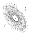
- FIG. 3 is a perspective view of the axial gap direct drive generator of FIG. 1 in isolation, illustrating its open, spoked configuration;
- FIG. 4 is a perspective view of another embodiment of a rotor of an axial gap direct drive generator, illustrating a solid disk configuration
- FIG. 5 is a cross-sectional view of the perimeter of the axial gap direct drive generator of FIG. 1 , illustrating its gap-maintaining rolling supports;
- FIG. 6 is a cross-sectional view similar to the view of FIG. 5 , illustrating another embodiment of an axial gap direct drive generator with two sets of gap-maintaining rolling supports;
- FIG. 7 is a cross-sectional view of the arrangement of yet another embodiment of an axial gap direct drive generator that includes two axial air gaps and a single set of gap-maintaining rolling supports;
- FIG. 8 is a cross-sectional view of the arrangement of yet another embodiment of an axial gap direct drive generator, taken through Line 8 - 8 of FIG. 3 , that includes two axial air gaps and two sets of gap-maintaining rolling supports;
- FIG. 9 is a perspective view of another embodiment of a joint between a hub and a rotor
- FIG. 10 is a perspective view of a generator according to another embodiment of the invention carried by and coupled to a wind turbine;
- FIG. 11 is an exploded perspective view of the generator of FIG. 10 , illustrating the coupling or connection between the wind turbine and the generator;
- FIG. 12 is a cross-sectional view of a portion of the generator, taken through Line 12 - 12 of FIG. 10 ;
- FIG. 13 is a cross-sectional view of a generator that employs two sets of angled gap-maintaining rolling supports according to yet another embodiment of the invention.
- FIG. 14 is a perspective view of a generator-wind turbine connector for the generator of FIG. 13 .
- FIG. 1 is a perspective view of a direct drive generator, generally indicated at 10 , according to one embodiment of the invention, shown as installed in a wind turbine 12 .
- the direct drive generator 10 is illustrated as being installed in a wind turbine 12 , as those of skill in the art will realize, direct drive generators 10 according to embodiments of the invention may be used in other contexts and as parts of other types of systems.
- wind turbines 12 may be configured and adapted to function synergistically with direct drive generators 10 according to embodiments of the invention. For that reason, a description of certain features of the wind turbine 12 is provided.
- the wind turbine 12 of FIG. 1 is installed on a floating underwater support structure 14 , although the wind turbine 12 may be installed on any type of land- or sea-based structure.
- the particular details of the illustrated floating underwater support structure 14 are disclosed in commonly-assigned U.S. Pat. No. 8,197,208, the contents of which are incorporated by reference herein in their entirety.
- the floating underwater support structure 14 of FIG. 1 comprises a truss structure 15 in the shape of an inverted pyramid or frustum that can sustain tensile and compressive loads and bending moments.
- the bottom of the truss structure 15 is connected to a joint 17 that allows pitch, roll, and yaw rotation.
- a buoyant member 19 At the top of the truss structure 15 , typically a few meters below the level of the water, a buoyant member 19 provides a buoyant force that is at least equal to the weight of the floating underwater support structure 14 and any structure, such as the wind turbine 12 , that is mounted on it.
- the floating underwater support structure 14 is particularly suited for structures that need to remain upright or substantially upright in water, but that can tolerate some degree of acceleration and changes in angular position.
- the generator 10 may be used in essentially any application, there are certain advantages to using it with the underwater support structure 14 .
- the wind turbine 12 has a primary support member or tower 16 and two secondary support members 18 that join the primary support member 16 at approximately its halfway point. At its top, the primary support member 16 supports an axle 20 , on which a hub 22 is mounted for rotation. Two blades 24 extend from the hub 22 , although a wind turbine 12 may have any number of blades. The blades 24 may be mounted to the hub 22 using pitch bearings, which would allow the wind turbine 12 to change the angle of attack of its blades 24 . Other conventional techniques for controlling the angle of attack, shape, and other characteristics of the blades 24 may be used in order to control the manner in which the wind turbine 12 governs the amount of power generated.
- the wind turbine 12 may use stall control, in which the blades 24 are shaped such that at extremely high speeds, the shape of the blades 24 causes them to stall and moderate the power generated.
- the blades 24 may include control surfaces that extend, retract, and actively change the shape of the blades 24 in order to control their speed and power output.
- a set of tension cable supports 26 provide additional support to the primary support member 16 by counteracting those bending moments.
- FIG. 1 the direct drive generator 10 is directly integrated into the hub 22 .
- FIG. 2 is an enlarged perspective view of the direct drive generator 10 and the hub 22 in isolation.
- the direct drive generator 10 is carried within an elongate slot or opening 28 in the hub 22 , although it may be attached to the hub 22 in other ways.
- the hub 22 itself may be made of a metal, such as steel or aluminum; a composite material, such as a glass fiber or carbon fiber composite; or any other suitable material. In some embodiments, parts of the hub 22 may be made of different materials, for example, with one part of the hub made of a metal while another is made of a composite. Moreover, as shown in FIG. 2 , the hub 22 is fully symmetrical front-to-back. However, in other embodiments, the hub 22 may not be symmetrical. Instead, the front of the hub 22 may be thinner than the rear, or the rear may be thinner than the front, depending on the anticipated loads and other conventional factors.
- the hub 22 and blades 24 may be advantageous to construct the hub 22 and blades 24 as a single piece, as a single-piece hub and blades combination may be lighter than a comparable hub 22 and blades 24 made in multiple pieces. In this case some form of control other than pitch control would need to be utilized to control the power.
- the direct drive generator 10 may be mounted to the hub 22 in a number of ways. As was noted briefly above, in the embodiment illustrated in FIG. 2 , the hub 22 has a large, central longitudinal opening 28 . Channels 30 are secured at the top and bottom of the longitudinal central opening 28 . The rotor 32 of the direct drive generator 10 is mounted to the hub 22 via the channels 30 . The hub 22 also has a round axial opening 34 through which the axle 20 passes, thereby mounting the hub 22 on the axle 20 . Conventional bearings, not shown in FIG. 2 , would generally be used between the hub 22 and the axle 20 to facilitate rotation.
- FIG. 3 is a perspective view of the generator 10 in isolation.
- the rotor 32 is generally circular in overall shape and includes its own central opening 36 to allow it to fit over the axle 20 .
- the rotor 32 is carried entirely by the hub 22 , and thus, it need not bear on or against or be directly connected to the axle 20 .
- the central opening 36 of the rotor 32 need not be round and need not be particularly shaped to fit over the axle 20 .
- the rotor may be mounted to the axle 20 , or to any conventional shaft, by a conventional bearing. In those cases, the central opening 36 of the rotor 32 would be sized and shaped for the shaft on which it is mounted.
- the stator 38 of the direct drive generator 10 also has a central opening 40 through which the axle 20 passes, mounting the stator 38 fixedly on the axle 20 .
- Both the rotor 32 and the stator 38 have an open, spoked configuration in which the circular perimeter 42 of the rotor 32 and the corresponding circular perimeter 44 of the stator 38 , when assembled, are solid, contiguous metal channels or shapes, as will be described below, and a number of spokes 46 extend through the middle of the rotor 32 and stator 38 to support the perimeters or peripheral portions 42 , 44 .
- the rotor 32 and stator 38 may be made in segments that are assembled prior to installation.
- the peripheral portion 42 of the rotor 32 and the peripheral portion 44 of the stator 38 are configured as a rotor ring and a stator ring, respectively.
- the spokes 46 are arranged in the general shape of a six-pointed star; they extend from one part of the rotor's periphery or perimeter 42 to another without crossing through its center, leaving an opening 36 of sufficient dimension for the axle 20 to pass through.
- the spokes 46 connect the perimeter 44 with a central ring 48 that mounts the stator 38 on the axle 20 .
- the rotor 32 may also have a central ring to which the spokes 46 connect, and its spokes may be arranged in the same way as those of the stator 38 .
- radial refers to a direction along the radius or diameter of the rotor 32 or stator 38 .
- axial refers to a direction orthogonal to the radial direction along the axis of rotation.
- FIG. 4 is a perspective view of another embodiment of a rotor 300 of a direct drive generator.
- the perimeter 302 is connected to a central ring 304 that defines an opening 306 by a solid portion 308 .
- the solid portion 308 may have openings or open areas.
- the mechanical energy of the blades 24 can be transferred directly to the generator 10 .
- the blades 24 and hub 22 drive a shaft, and the generator may be installed elsewhere on that shaft.
- FIG. 5 is a sectional view of the perimeters of a rotor and a stator according to one embodiment of the invention. It should be understood that the rotor and stator depicted in FIG. 5 are slightly different than the rotor and stator depicted in FIGS. 2 and 3 , insofar as the generator 10 illustrated in FIGS. 2 and 3 has a rotor with a perimeter or peripheral portion that fully extends around and encloses the perimeter or peripheral portion of the stator. Those kinds of embodiments will be described below with respect to FIGS. 7 and 8 . However, for the sake of convenience in description, FIGS. 5 and 6 use the same reference numerals used in FIGS. 2 and 3 to identify the rotor 32 , the stator 38 , and certain of their components.
- the perimeter or peripheral portion 42 of the rotor 32 comprises a Z-channel.
- the rotor 32 On an inner face 50 of the Z-channel, mounted on a back iron (not shown), the rotor 32 includes a plurality of magnetic elements 52 , each evenly spaced from one another, and each positioned facing the stator 38 .
- the perimeter or peripheral portion 44 of the stator 38 which is positioned in close proximity to the rotor 32 , comprises a C-channel in the illustrated embodiment.
- the rotor 32 and stator 38 would be made of a metal, such as steel.
- the stator 38 carries a plurality of stator teeth 54 on a back iron (not shown), evenly spaced around its perimeter, arranged facing the rotor 32 .
- Each stator tooth 54 has windings/coils 56 either wound around each tooth or wound around several teeth in distributed fashion with each coil extending approximately a magnetic pole pitch in the circumferential direction.
- An air gap 58 is maintained between the magnetic elements 52 of the rotor 32 and the stator teeth 54 of the stator 38 .
- the air gap 58 extends in the axial direction, and for this reason, is referred to in this description as an “axial air gap.”
- the magnetic elements 52 and stator teeth 54 may be arranged in any conventional pattern relative to one another, and they may be wired electrically in any conventional fashion. For example, they may be in an A-B-C pattern with three stator teeth 54 for each pole-pair of magnets.
- the rotor 32 and stator 38 may or may not be electrically divided into two or more segments.
- the direct drive generator 10 may be divided into four segments, with 122 magnetic poles per segment and a total of 488 magnetic poles. In other embodiments, 480 , 640 , or some other number of poles may be used, depending on the diameter of the generator 10 and other factors.
- the generator 10 as a whole may generate 5-10 MW and run at 690 V, although higher voltages of 1.38 kV, 2.4 kV, 3.3 kV or 4.6 kV may be used. Any other known or compatible electrical configurations may also be used.
- the air gap 58 would be on the order of a few millimeters, such as 5-10 mm, while the overall generator 10 would have a diameter on the order of 3 to 20 m.
- the generator 10 includes gap-maintaining elements, which in this case are sets of rolling supports 60 , 62 that bear between the rotor 32 and the stator 38 , as well as between the stator 38 and an external channel 64 that rotates with the hub 22 .
- these sets of rolling supports 60 , 62 are trains of wheels that are arranged around the perimeters 42 , 44 of the rotor 32 and stator 38 along with the magnetic elements 52 and the stator teeth 54 .
- the first set of rolling supports 60 are mounted on respective axles 64 for rotation within a bracket 66 provided at the top of the rotor 32 , above (i.e., radially outward of) the air gap 58 .
- the first set of rolling supports 60 bears against a race or track 68 provided along the inward face of the stator 38 .
- the second set of rolling supports 62 is also mounted for rotation on an axle 70 within a bracket 65 that is mounted to the hub 22 and extended only for the width of the hub 22 , bear against a race or track 72 that lies on the opposite face of the stator 38 .
- both sets of rolling supports 60 , 62 are positioned above (i.e., radially outward of) the air gap 58 .
- the sets of rolling supports 60 , 62 and the tracks 68 , 72 against which they bear, and any other structures prone to wear may be made of a non-magnetic material, such as stainless steel. If those structures are made of stainless steel or other non-magnetic materials, any shavings or particles that may be created by wear will not be attracted to and attach to the magnets.
- the individual support wheels 60 , 62 may be on the order of 100-200 mm in diameter.
- the rotor 32 and stator 38 may also include seals to seal and isolate the magnetic components from the other components and to prevent them from being fouled by debris and environmental conditions.
- the seal may be pressure-tight and conditioned air or another gas may be pumped into the sealed area.
- FIGS. 6-8 illustrate a number of embodiments that are variations on the basic concepts illustrated in FIG. 5 .
- FIG. 6 is a cross-sectional view similar to the view of FIG. 5 , illustrating another embodiment of the invention.
- the sets of rolling supports 60 , 62 are positioned above (i.e., radially outward of) the air gap 58 .
- a set of rolling supports 74 is mounted within a bracket 78 attached to a lower portion of the Z-channel that defines the perimeter 42 of the rotor 32 , such that the set of rolling supports 74 is below (i.e., radially inward of) the air gap 58 .
- the lower set of rolling supports 74 bears against a track 80 provided on the inward face of the stator 38 .
- the lower set of rolling supports 74 may be offset in angular position from the other rolling supports 60 , 62 .
- one of the rolling supports 74 and its bracket 78 are seen in elevation, rather than cross-section, because they are behind the plane through which the cross-section of FIG. 6 is taken.
- a second air gap may be provided, axially opposite the location of the first air gap.
- FIG. 7 is a cross-sectional view similar to the views of FIGS. 5-6 illustrating a generator 100 that includes two air gaps. More particularly, the generator 100 includes a rotor 102 that, along its outer radial edge, forms a channel that extends around and over the top of the stator 104 , thus enclosing the stator 104 on three sides. The left and right inwardly-facing sides 106 , 108 of the rotor 102 carry respective sets of magnetic elements 110 , 112 .
- the stator 104 has a central, radially-extending portion 114 . Each face of the radially-extending portion 114 carries a set of stator teeth 116 , 118 and associated windings/coils 120 , 122 .
- the generator 100 of FIG. 5 includes two air gaps 124 , 126 , one air gap 124 , 126 between each pair of magnetic elements 110 , 112 and stator teeth 116 , 118 .
- the two opposing sets of magnetic elements 110 , 112 and stator teeth 116 , 118 serve to balance the mechanical forces on the rotor 102 and stator 104 .
- the sets of magnetic elements 110 , 112 and stator teeth 116 , 118 may be sized so as to produce equal amounts of axially directed force.
- a pair of seals 128 , 130 extending between the inward walls 106 , 108 of the rotor 102 and the stator 104 seals the compartment created by the rotor 102 , thus isolating the electrical generating structure from other components.
- a single set of rotating supports 130 is mounted on corresponding sets of brackets to bear between the inner face 106 of the rotor 102 and a radially inwardly projecting portion 134 of the stator 104 .
- a track 136 is provided on the face of the stator portion 134 against which the set of rotating supports 130 bear.
- FIG. 8 is a cross-sectional view of another embodiment of an axial gap direct drive generator, generally indicated at 200 .
- the perimeter of the rotor 202 forms a generally square or rectangular tube, extending around all four sides.
- An opening 204 admits the perimeter of the stator 206 .
- the perimeter of the stator 206 has the general shape of an inverted “T.”
- An axial portion 208 serves to connect to the spokes or disk that connect the perimeter of the stator 206 to its center support.
- a radially-extending portion 210 connects to and extends from the axial portion 208 .
- the left and right inwardly-facing sides 212 , 214 of the rotor 202 carry respective sets of magnetic elements 216 , 218 .
- the magnetic elements 216 , 218 face the radially-extending portion 210 of the stator 206 .
- the radially-extending portion 210 of the stator 206 carries stator teeth and backiron 220 , 222 with associated windings 224 , 226 that face the magnetic elements 216 , 218 , thereby defining two air gaps 228 , 230 .
- the magnetic elements 216 and corresponding stator teeth 220 are radially larger than the pair of magnetic elements and stator teeth 218 , 222 on the other side of the stator 206 , thus embodying the 55%/45% split explained above.
- the pairs of magnetic elements 216 , 218 and stator teeth and backiron 220 , 222 may be of the same size so as to generate the same amount of magnetic force.
- a pair of seals 232 , 234 provides isolation for the electrical and magnetic elements of the generator.
- a pair of seals 232 , 234 arranged symmetrically to bear between the left and right inwardly-facing sides 212 , 214 of the rotor 202 and the respective faces of the radially-extending portion 210 of the stator 206 are two sets of rotating elements 236 , 238 .
- Each of the rotating elements 236 , 238 is mounted on an axle 240 , 242 that is held by a bracket 244 , 246 , and each bears against a track 248 , 250 on a face of the radially-extending portion 210 of the stator 206 .
- the sets of rotating elements 130 , 236 , 238 may not need to be made of a non-ferromagnetic material such as stainless steel. Instead, any material that can resist corrosion and/or other operating conditions may be used. It should be understood that most, if not all, embodiments would have some sort of sealing structure, although for the sake of simplicity, seals are not shown in the views of FIGS. 5 and 6 .
- the gap-maintaining rolling supports are sets or trains of wheels.
- rotational bearings of various sorts may be used instead of wheels.
- any element that can bear between the rotor and the stator to maintain the axial air gap without undue wear may be used in embodiments of the invention.
- Axial gap direct drive generators 10 , 100 , 200 may be used in wind turbines 12 and in other applications. As was noted briefly above, when used in various applications, the generators 10 , 100 , 200 may be mounted in various ways. The mounting of the generator 10 described above with respect to FIGS. 1 and 2 allows the hub 22 to transmit both torque and axial loads to the generator 10 .
- FIG. 9 is a perspective view of a portion of a hub 400 with a portion of a generator 402 .
- the hub 400 has an elongate central slot 403 in which a hinging connector 404 is mounted.
- the hinging connector 404 may be mounted to a channel connected to the slot 403 ; in other embodiments, the hinging connector 404 may be secured directly to the slot 403 .
- the hinging connector 404 has a rounded cylindrical upper portion 406 , a rounded cylindrical lower portion 408 , and a web or strip of material 410 between the upper and lower portions 406 , 408 .
- the upper and lower portions 406 , 408 each have a pair of endcaps 414 , 416 , 418 , 420 that attach to the generator 402 and the hub 400 , respectively.
- the endcaps 414 , 416 , 418 , 420 also mount the upper and lower portions 406 , 408 for rotation, by means of axle portions 422 , 424 , 426 , 428 that extend from the respective endcaps 414 , 416 , 418 , 420 into corresponding openings 430 , 432 , 436 , 438 provided within the ends of the upper and lower portions 406 , 408 .
- the hinging connector 404 can rotate about both of its upper and lower portions 406 , 408 , providing for movement in the axial direction, but can still transmit torques.
- a second hinging connector 404 would be installed at the bottom of the hub 400 as well.
- the hub 400 of a wind turbine may deflect or move on the order of an inch (2.54 cm) or more in the axial direction as wind on the blades creates axial loads.
- the presence of the hinging connector 404 allows the hub 400 to move in the axial direction, as indicated by the arrows in FIG. 9 , so that the loads are not transferred to the generator 402 .
- FIG. 10 is a perspective view of a wind turbine and generator assembly, generally indicated at 450 .
- a wind turbine 452 is supported on a tower or vertical support 454 .
- the turbine 452 itself includes a number of blades 456 that are driven by the wind to rotate about an axle 458 .
- the generator 460 is carried on the axle 458 and is coupled to the rotating blades 456 of the wind turbine 452 by two connectors 462 , which support and transmit force to the generator 460 .
- FIG. 11 is an exploded perspective view of a portion of the assembly 450 of FIG. 10 , illustrating a connector 462 and the manner in which the turbine 452 and generator 460 are coupled together.
- the rotor 464 of the generator 460 has a radially outwardly extending projection 466 with two generally cylindrical engaging prongs 468 at its furthest extent.
- An engaging piece 470 attached to the blade 456 has cavities 472 and a general shape designed to mate with and engage the projections 466 on the generator 460 .
- the generator 460 is supported by the axle 458 and coupled to the turbine 452 by the two connectors 462 .
- the connectors 462 transmit rotational force and induce rotational motion of the generator 460 .
- the connectors 462 will not transmit axial force or motion to the generator 460 .
- This may be helpful because the blades 456 of the turbine 452 are often buffeted by the wind while in use, causing them to flex, e.g., in the plane orthogonal to the plane of FIGS. 10 and 11 , which is the axial direction with respect to the generator 460 .
- the two complementary pieces of the connector 466 , 470 may simply slip relative to each other, rather than transmitting the force or motion of the blade 456 .
- the generator 460 itself is similar in many respects to the generators 10 , 100 , 200 described above. It is a “direct drive” or “ring” generator, with the rotor and stator arranged together in a circumferential “ring” supported by spokes.
- the generator 460 may be assembled from a plurality of segments. In the illustrated embodiment, the generator 460 is assembled from 48 straight segments, meaning that the generator 460 is actually polygonal, rather than circular, although it may be fully or substantially circular in other embodiments, and portions of the following description may assume that the generator 460 is circular.
- spokes 474 from the stator of the generator 460 extend radially and connect with the axle 458 ; spokes 476 from the rotor 464 are arranged as chords in a circle—those spokes 476 extend between and support various points around the circumference of the generator 460 without transiting the center or connecting to the axle 458 .
- FIG. 12 is a cross-sectional view of the generator 460 , taken through Line 12 - 12 of FIG. 10 .
- the arrangement of the generator 460 is somewhat similar to the arrangement of the generator 200 described above; however, the “sense” of some of the components is reversed.
- the rotor 464 is essentially T-shaped, and carries trains of magnetic elements 478 and their respective back irons 480 on both sides of its central web 482 .
- Corresponding sets of stator teeth 482 with coils 484 are carried on inner faces of a generally Y-shaped stator 486 , defining a pair of air gaps 488 between respective sets of magnetic elements 478 and stator teeth 482 .
- the two sets of magnetic elements 478 and stator teeth 482 are of the same or approximately the same size, although they may be of different sizes as set forth above with respect to generator 200 . While the rotor 464 and the stator 486 may be made of a metal, as was described above, in the illustrated embodiment, these components 464 , 486 are made of composite materials, such as glass fiber or carbon fiber composite.
- two sets of rolling gap supports 490 are carried by the stator 486 and bear between the rotor 464 and the stator 486 .
- the sets of rolling gap supports 490 are held by brackets 492 on the stator 486 to bear against wear plates 494 arranged on either side of the central web 482 of the rotor 464 , near its bottom.
- the rolling gap supports 490 rotate about essentially vertical axles 496 and extend essentially horizontally between the rotor 464 and the stator 486 .
- the shape of the two connectors 462 helps to ensure that the rotor 464 and stator 486 remain in alignment with one another.
- the generator 460 forms an essentially entirely sealed enclosure, with seals 498 extending between inner faces of the rotor 464 and outer faces of the stator 486 .
- FIG. 12 also illustrates more of the details of how the rotor 464 and stator 486 are assembled into the generator 460 .
- FIG. 12 illustrates the rotor spokes 476 and stator spokes 474 .
- the stator 486 is generally Y-shaped, it actually has two halves 500 , 502 that meet at a ring-shaped bar 503 which in turn is connected to the spokes 474 .
- the two halves 500 , 502 are bolted to the ring-shaped bar 503 with one or more bolts 504 .
- the entire stator 486 can be disassembled from the rotor 464 .
- FIG. 13 is a cross-sectional view of generator, generally indicated at 550 , according to another embodiment of the invention.
- the generator 550 is very similar to the generator 460 of FIG. 12 , except that in the generator 550 , the sets of rolling gap supports 554 that help to maintain the two air gaps 556 are not horizontal; rather, they are angled toward the vertical, as will be described below in more detail.
- the peripheral portion of the rotor ring 552 of generator 550 is generally T-shaped with a central web 558 that carries magnetic elements 560 and their back irons 562 .
- the central web 558 of the peripheral portion of the rotor ring 552 terminates at its lowest point with a generally trapezoidal bearing block 564 .
- a set of wear plates 566 are provided on the angled faces of the bearing block 564 , such that the angled rolling gap supports 554 bear against the wear plates 566 .
- the peripheral portion of the stator ring 568 is generally W-shaped and carries sets of stator teeth 570 with windings 572 on respective left and right inner faces 577 , 579 in proximity to the magnetic elements 560 to form the air gaps 556 .
- Angled brackets 569 below (i.e., radially inward of) the air gaps 556 hold the sets of rolling gap supports 554 at an angle toward the vertical, as was noted briefly above.
- the rolling gap supports 554 will be more horizontal than vertical, i.e., in most embodiments, they will be positioned at an angle between about 0° and about 45°.
- the peripheral portion of the stator ring 568 includes downwardly-extending portions 571 , 573 that mate with a ring-shaped central bar 503 .
- the generator 550 is comprised of two halves that meet and attach at the ring-shaped bar 503 .
- the ring-shaped bar 503 is, in turn, attached to the spokes 474 .
- the peripheral portion of the rotor ring 552 and the peripheral portion of the stator ring 568 of the generator 550 form a sealed enclosure. Seals 498 between respective left and right sidewall portions 581 , 583 of the peripheral portion of the rotor ring 552 and the peripheral portion of the stator ring 568 seal the enclosure against weather and other forms of contamination.
- FIG. 14 is a perspective view of another embodiment of a connector 600 that is particularly suited for use with generator 550 of FIG. 13 , illustrating how generator 550 may be connected to a wind turbine so as to be driven by it.
- the angle of the sets of rolling supports 554 may make the generator 550 better able to maintain the magnetic elements 560 and the sets of stator teeth 570 in alignment with each other if the generator 550 is subjected to loads and thrusts in the radial direction. For that reason, there may be less need for a connector like connector 462 , which constrains motion in the radial direction and helps to maintain the components in alignment.
- a tapering projection 602 is attached to the wind turbine.
- the projection 602 is received between two raised projections 604 on the generator 550 that extend transversely to the projection 602 from the generator 550 and essentially define a slot for the projection 602 .
- the projections 604 from the generator 550 have a generally round shape at the surfaces where they engage the projection 602 from the wind turbine.
- the wind turbine can transmit force in the direction of arrow F 1 , i.e., in the circumferential direction to drive the generator 550 , but does not transmit force in the direction of arrow F 2 .
- the connector 600 allows the wind turbine to drive the generator 550 without transmitting any forces that might be created by wind buffeting of the turbine blades. Additionally, the connector 600 does not support or “hold up” the rotor.
- generators 10 , 100 , 200 , 460 , 550 may be used in essentially any application, they may be particularly suited for sea-based applications or other applications in which accelerations and changes in angular position are likely. That is because the gap-maintaining rolling supports, and the arrangement of the axial air gap or gaps in general, make the generators 10 , 100 , 200 , 460 , 550 more robust, in that they are less sensitive to accelerations and changes in position.
- generators 10 , 100 , 200 , 460 , 550 being used in a vertical orientation
- generators 10 , 100 , 200 , 460 , 550 according to embodiments of the invention could be used vertically, horizontally, or at any angular position between vertical and horizontal.
- generators 10 , 100 , 200 , 460 , 550 according to embodiments of the invention are particularly suitable for use with floating underwater support structures 14 that allow some degree of acceleration and changes in angular position.
Abstract
Description
Claims (20)
Priority Applications (1)
| Application Number | Priority Date | Filing Date | Title |
|---|---|---|---|
| US13/743,187 US9270150B2 (en) | 2009-12-16 | 2013-01-16 | Axial gap rotating electrical machine |
Applications Claiming Priority (4)
| Application Number | Priority Date | Filing Date | Title |
|---|---|---|---|
| US28715709P | 2009-12-16 | 2009-12-16 | |
| US31414610P | 2010-03-15 | 2010-03-15 | |
| US12/968,670 US8373299B2 (en) | 2009-12-16 | 2010-12-15 | Axial gap rotating electrical machine |
| US13/743,187 US9270150B2 (en) | 2009-12-16 | 2013-01-16 | Axial gap rotating electrical machine |
Related Parent Applications (1)
| Application Number | Title | Priority Date | Filing Date |
|---|---|---|---|
| US12/968,670 Continuation-In-Part US8373299B2 (en) | 2009-12-16 | 2010-12-15 | Axial gap rotating electrical machine |
Publications (2)
| Publication Number | Publication Date |
|---|---|
| US20130200630A1 US20130200630A1 (en) | 2013-08-08 |
| US9270150B2 true US9270150B2 (en) | 2016-02-23 |
Family
ID=48902250
Family Applications (1)
| Application Number | Title | Priority Date | Filing Date |
|---|---|---|---|
| US13/743,187 Active 2032-07-16 US9270150B2 (en) | 2009-12-16 | 2013-01-16 | Axial gap rotating electrical machine |
Country Status (1)
| Country | Link |
|---|---|
| US (1) | US9270150B2 (en) |
Cited By (3)
| Publication number | Priority date | Publication date | Assignee | Title |
|---|---|---|---|---|
| US20160061192A1 (en) * | 2013-04-18 | 2016-03-03 | Marc Guyot | Floating wind turbine structure |
| US20170342957A1 (en) * | 2014-07-02 | 2017-11-30 | Energy Technologies Institute Llp | Support structure for tidal energy converter system |
| US11891979B2 (en) | 2018-09-20 | 2024-02-06 | Eolink S.A.S. | Floating wind turbine with controllable yaw position |
Families Citing this family (6)
| Publication number | Priority date | Publication date | Assignee | Title |
|---|---|---|---|---|
| KR102229658B1 (en) | 2015-04-30 | 2021-03-17 | 구글 엘엘씨 | Type-agnostic rf signal representations |
| DE102017119530A1 (en) * | 2017-08-25 | 2019-02-28 | Wobben Properties Gmbh | Generator rotor and generator stator and generator and wind turbine and method for transporting a generator |
| EP3477820B1 (en) | 2017-10-26 | 2021-02-24 | Jan-Dirk Reimers | Electrical ring machine for inverter operation |
| EP3503358A1 (en) | 2017-12-21 | 2019-06-26 | Jan-Dirk Reimers | Construction kit for an electric ring machine |
| WO2020088724A1 (en) * | 2018-11-02 | 2020-05-07 | Vestas Wind Systems A/S | A self-aligning interface |
| CN110943555A (en) * | 2019-11-21 | 2020-03-31 | 新疆金风科技股份有限公司 | Device with stator and rotor and wind generating set |
Citations (54)
| Publication number | Priority date | Publication date | Assignee | Title |
|---|---|---|---|---|
| US2177801A (en) | 1937-02-04 | 1939-10-31 | Erren Rudolf Arnold | Electric generator |
| US3789252A (en) | 1971-02-24 | 1974-01-29 | Bbc Brown Boveri & Cie | Two-part stator for large rotating electrical machines |
| US4449889A (en) | 1983-01-20 | 1984-05-22 | Belden Ralph A | Windmill |
| US5057726A (en) | 1990-10-10 | 1991-10-15 | Westinghouse Electric Corp. | Structureborne vibration-compensated motor arrangement having back-to-back twin AC motors |
| USRE34268E (en) | 1980-05-10 | 1993-06-01 | Papst-Motoren Gmbh & Co. Kg | Brushless direct current motor system |
| US5315159A (en) * | 1989-10-12 | 1994-05-24 | Holec Projects B.V. | Wind turbine |
| US5599168A (en) | 1995-08-23 | 1997-02-04 | Lund; Arnold M. | Wind turbine adaptable to wind direction and velocity |
| US6064123A (en) * | 1995-10-13 | 2000-05-16 | Gislason; Nils Erik | Horizontal axis wind turbine |
| US6177735B1 (en) | 1996-10-30 | 2001-01-23 | Jamie C. Chapman | Integrated rotor-generator |
| US6492756B1 (en) | 2000-04-05 | 2002-12-10 | Wavecrest Laboratories, Llc | Rotary electric motor having magnetically isolated stator and rotor groups |
| US6664655B2 (en) | 2001-12-31 | 2003-12-16 | Charles S. Vann | Multaxel windmill |
| US20040041409A1 (en) * | 2002-08-30 | 2004-03-04 | Gabrys Christopher W. | Wind turbine |
| US6727600B1 (en) | 2002-11-18 | 2004-04-27 | Ilich Abdurachmanov | Small underwater generator with self-adjusting axial gap |
| US6759758B2 (en) | 2002-06-13 | 2004-07-06 | Manuel Torres Martinez | Wind turbines for electrical power generation |
| US20040169376A1 (en) | 2001-07-06 | 2004-09-02 | Jacques Ruer | Offshore wind turbine and method for making same |
| US6791222B1 (en) | 2002-04-30 | 2004-09-14 | Wavecrest Laboratories, Llc | Rotary electric motor having at least two axially air gaps separating stator and rotor segments |
| US6836028B2 (en) * | 2001-10-29 | 2004-12-28 | Frontier Engineer Products | Segmented arc generator |
| US20050155346A1 (en) | 2001-09-25 | 2005-07-21 | Thomas Nikolaus | Wind power machine |
| US20060062676A1 (en) | 2002-12-17 | 2006-03-23 | Martin Jakubowski | Method for realising a submerged floating foundation with blocked vertical thrust for the coordinated production of mariculture and electrical energy using wind in open sea conditions and submergeable floating foundation for carrying loads to be used in said method |
| US20060071575A1 (en) | 2004-09-27 | 2006-04-06 | General Electric Company | Electrical machine with double-sided stator |
| US7075189B2 (en) | 2002-03-08 | 2006-07-11 | Ocean Wind Energy Systems | Offshore wind turbine with multiple wind rotors and floating system |
| US20060158055A1 (en) | 2005-01-14 | 2006-07-20 | Gennadii Ivtsenkov | Tangential induction dynamoelectric machines |
| US7119453B2 (en) | 2004-04-19 | 2006-10-10 | Northern Power Systems, Inc. | Direct drive wind turbine |
| US20060269362A1 (en) | 2003-05-21 | 2006-11-30 | Henriksen Svein D | Arrangement for anchoring a floating structure |
| US7154191B2 (en) | 2004-06-30 | 2006-12-26 | General Electric Company | Electrical machine with double-sided rotor |
| US7156586B2 (en) | 2003-01-06 | 2007-01-02 | Vestas Wind Systems A/S | Wind turbine with floating foundation |
| US7156037B2 (en) | 2002-05-22 | 2007-01-02 | Sway As | Device for a wind power station placed in deep water |
| US20070036657A1 (en) | 2003-04-28 | 2007-02-15 | Aloys Wobben | Rotor blade for a wind power system |
| US7180204B2 (en) | 2005-01-07 | 2007-02-20 | General Electric Company | Method and apparatus for wind turbine air gap control |
| US7186083B2 (en) * | 2002-06-06 | 2007-03-06 | Elliott Bayly | Wind energy conversion device |
| US20070075548A1 (en) | 2005-10-05 | 2007-04-05 | General Electric Company | Removable bearing arrangement for a wind turbine generator |
| US7202584B2 (en) | 2004-05-21 | 2007-04-10 | Nippon Thompson Co. Ltd. | Position-control stage system |
| US7204673B2 (en) | 2000-11-23 | 2007-04-17 | Aloys Wobben | Method of controlling a wind power installation |
| US20070200349A1 (en) | 2005-07-26 | 2007-08-30 | Bacon C R | Wind wheel and electricity generator using same |
| US20070207028A1 (en) | 2004-04-22 | 2007-09-06 | Peter Nicholas | Water current turbine |
| US20070214632A1 (en) | 2006-03-15 | 2007-09-20 | Fujitsu General Limited | Method for manufacturing a stator core for an axial air-gap electronic motor |
| US7293960B2 (en) | 2003-10-23 | 2007-11-13 | Shigeyuki Yamamoto | Power generation assemblies, and apparatus for use therewith |
| US7315102B2 (en) | 2003-12-15 | 2008-01-01 | Nissan Motor Co., Ltd. | Axial gap motor |
| US20080012346A1 (en) | 2006-07-11 | 2008-01-17 | Hamilton Sundstrand | Wind-turbine with load-carrying skin |
| US7355309B2 (en) | 2004-08-06 | 2008-04-08 | Northern Power Systems, Inc. | Permanent magnet rotor for a direct drive generator or a low speed motor |
| JP2008099344A (en) | 2006-10-05 | 2008-04-24 | Kayaba Ind Co Ltd | Axial air gap type motor |
| US20080161189A1 (en) | 2004-08-09 | 2008-07-03 | Clive Lewis | Superconducting Electrical Machines |
| US20080272602A1 (en) | 2006-03-24 | 2008-11-06 | Unison Co., Ltd. | Wind Turbine |
| US7456515B2 (en) | 2003-08-27 | 2008-11-25 | Norsk Hydro Asa | Wind turbine for use offshore |
| US7456534B2 (en) * | 2003-01-27 | 2008-11-25 | Newgen Generator Ab | Rotating electrical machine |
| US7482720B2 (en) | 2001-06-06 | 2009-01-27 | Evolving Generation Limited | Rotor and electrical generator |
| WO2009016372A2 (en) | 2007-07-30 | 2009-02-05 | Subsea Energy (Scotland) Limited | Wind energy generation apparatus |
| US7579744B2 (en) | 2004-12-14 | 2009-08-25 | Nissan Motor Co., Ltd. | Rotor structure of an axial gap rotating electrical device |
| US20090243301A1 (en) | 2008-03-25 | 2009-10-01 | General Electric Company | Wind turbine direct drive airgap control method and system |
| US7612462B2 (en) | 2007-10-08 | 2009-11-03 | Viterna Larry A | Floating wind turbine system |
| US7646132B2 (en) | 2007-05-02 | 2010-01-12 | Empire Magnetics Inc. | Arcuate coil winding and assembly for axial gap electro-dynamo machines (EDM) |
| US7687932B2 (en) | 2001-09-13 | 2010-03-30 | High Technology Investments B.V. | Wind power generator and bearing structure therefor |
| US7709971B2 (en) | 2007-08-13 | 2010-05-04 | Shrikrishna Sane | Linear wind-powered electric generator |
| US20100133838A1 (en) | 2007-04-12 | 2010-06-03 | Sway As | Turbine rotor and power plant |
-
2013
- 2013-01-16 US US13/743,187 patent/US9270150B2/en active Active
Patent Citations (58)
| Publication number | Priority date | Publication date | Assignee | Title |
|---|---|---|---|---|
| US2177801A (en) | 1937-02-04 | 1939-10-31 | Erren Rudolf Arnold | Electric generator |
| US3789252A (en) | 1971-02-24 | 1974-01-29 | Bbc Brown Boveri & Cie | Two-part stator for large rotating electrical machines |
| USRE34268E (en) | 1980-05-10 | 1993-06-01 | Papst-Motoren Gmbh & Co. Kg | Brushless direct current motor system |
| US4449889A (en) | 1983-01-20 | 1984-05-22 | Belden Ralph A | Windmill |
| US5315159A (en) * | 1989-10-12 | 1994-05-24 | Holec Projects B.V. | Wind turbine |
| US5057726A (en) | 1990-10-10 | 1991-10-15 | Westinghouse Electric Corp. | Structureborne vibration-compensated motor arrangement having back-to-back twin AC motors |
| US5599168A (en) | 1995-08-23 | 1997-02-04 | Lund; Arnold M. | Wind turbine adaptable to wind direction and velocity |
| US6064123A (en) * | 1995-10-13 | 2000-05-16 | Gislason; Nils Erik | Horizontal axis wind turbine |
| US6177735B1 (en) | 1996-10-30 | 2001-01-23 | Jamie C. Chapman | Integrated rotor-generator |
| US6492756B1 (en) | 2000-04-05 | 2002-12-10 | Wavecrest Laboratories, Llc | Rotary electric motor having magnetically isolated stator and rotor groups |
| US7204673B2 (en) | 2000-11-23 | 2007-04-17 | Aloys Wobben | Method of controlling a wind power installation |
| US7482720B2 (en) | 2001-06-06 | 2009-01-27 | Evolving Generation Limited | Rotor and electrical generator |
| US20040169376A1 (en) | 2001-07-06 | 2004-09-02 | Jacques Ruer | Offshore wind turbine and method for making same |
| US7687932B2 (en) | 2001-09-13 | 2010-03-30 | High Technology Investments B.V. | Wind power generator and bearing structure therefor |
| US20050155346A1 (en) | 2001-09-25 | 2005-07-21 | Thomas Nikolaus | Wind power machine |
| US6836028B2 (en) * | 2001-10-29 | 2004-12-28 | Frontier Engineer Products | Segmented arc generator |
| US6664655B2 (en) | 2001-12-31 | 2003-12-16 | Charles S. Vann | Multaxel windmill |
| US7075189B2 (en) | 2002-03-08 | 2006-07-11 | Ocean Wind Energy Systems | Offshore wind turbine with multiple wind rotors and floating system |
| US6791222B1 (en) | 2002-04-30 | 2004-09-14 | Wavecrest Laboratories, Llc | Rotary electric motor having at least two axially air gaps separating stator and rotor segments |
| US7156037B2 (en) | 2002-05-22 | 2007-01-02 | Sway As | Device for a wind power station placed in deep water |
| US7186083B2 (en) * | 2002-06-06 | 2007-03-06 | Elliott Bayly | Wind energy conversion device |
| US6759758B2 (en) | 2002-06-13 | 2004-07-06 | Manuel Torres Martinez | Wind turbines for electrical power generation |
| US7042109B2 (en) | 2002-08-30 | 2006-05-09 | Gabrys Christopher W | Wind turbine |
| US20040041409A1 (en) * | 2002-08-30 | 2004-03-04 | Gabrys Christopher W. | Wind turbine |
| US6727600B1 (en) | 2002-11-18 | 2004-04-27 | Ilich Abdurachmanov | Small underwater generator with self-adjusting axial gap |
| US20060062676A1 (en) | 2002-12-17 | 2006-03-23 | Martin Jakubowski | Method for realising a submerged floating foundation with blocked vertical thrust for the coordinated production of mariculture and electrical energy using wind in open sea conditions and submergeable floating foundation for carrying loads to be used in said method |
| US7156586B2 (en) | 2003-01-06 | 2007-01-02 | Vestas Wind Systems A/S | Wind turbine with floating foundation |
| US7456534B2 (en) * | 2003-01-27 | 2008-11-25 | Newgen Generator Ab | Rotating electrical machine |
| US20070036657A1 (en) | 2003-04-28 | 2007-02-15 | Aloys Wobben | Rotor blade for a wind power system |
| US20060269362A1 (en) | 2003-05-21 | 2006-11-30 | Henriksen Svein D | Arrangement for anchoring a floating structure |
| US7456515B2 (en) | 2003-08-27 | 2008-11-25 | Norsk Hydro Asa | Wind turbine for use offshore |
| US7293960B2 (en) | 2003-10-23 | 2007-11-13 | Shigeyuki Yamamoto | Power generation assemblies, and apparatus for use therewith |
| US7315102B2 (en) | 2003-12-15 | 2008-01-01 | Nissan Motor Co., Ltd. | Axial gap motor |
| US7183665B2 (en) | 2004-04-19 | 2007-02-27 | Northern Power Systems, Inc. | Direct drive wind turbine |
| US7119453B2 (en) | 2004-04-19 | 2006-10-10 | Northern Power Systems, Inc. | Direct drive wind turbine |
| US20070207028A1 (en) | 2004-04-22 | 2007-09-06 | Peter Nicholas | Water current turbine |
| US7202584B2 (en) | 2004-05-21 | 2007-04-10 | Nippon Thompson Co. Ltd. | Position-control stage system |
| US7154191B2 (en) | 2004-06-30 | 2006-12-26 | General Electric Company | Electrical machine with double-sided rotor |
| US7355309B2 (en) | 2004-08-06 | 2008-04-08 | Northern Power Systems, Inc. | Permanent magnet rotor for a direct drive generator or a low speed motor |
| US20080161189A1 (en) | 2004-08-09 | 2008-07-03 | Clive Lewis | Superconducting Electrical Machines |
| US20060071575A1 (en) | 2004-09-27 | 2006-04-06 | General Electric Company | Electrical machine with double-sided stator |
| US7579744B2 (en) | 2004-12-14 | 2009-08-25 | Nissan Motor Co., Ltd. | Rotor structure of an axial gap rotating electrical device |
| US7180204B2 (en) | 2005-01-07 | 2007-02-20 | General Electric Company | Method and apparatus for wind turbine air gap control |
| US20060158055A1 (en) | 2005-01-14 | 2006-07-20 | Gennadii Ivtsenkov | Tangential induction dynamoelectric machines |
| US20070200349A1 (en) | 2005-07-26 | 2007-08-30 | Bacon C R | Wind wheel and electricity generator using same |
| US20080199309A1 (en) | 2005-10-05 | 2008-08-21 | General Electric Company | Removable bearing arrangement for a wind turbine generator |
| US20070075548A1 (en) | 2005-10-05 | 2007-04-05 | General Electric Company | Removable bearing arrangement for a wind turbine generator |
| US20070214632A1 (en) | 2006-03-15 | 2007-09-20 | Fujitsu General Limited | Method for manufacturing a stator core for an axial air-gap electronic motor |
| US20080272602A1 (en) | 2006-03-24 | 2008-11-06 | Unison Co., Ltd. | Wind Turbine |
| US20080012346A1 (en) | 2006-07-11 | 2008-01-17 | Hamilton Sundstrand | Wind-turbine with load-carrying skin |
| JP2008099344A (en) | 2006-10-05 | 2008-04-24 | Kayaba Ind Co Ltd | Axial air gap type motor |
| US20100133838A1 (en) | 2007-04-12 | 2010-06-03 | Sway As | Turbine rotor and power plant |
| US7646132B2 (en) | 2007-05-02 | 2010-01-12 | Empire Magnetics Inc. | Arcuate coil winding and assembly for axial gap electro-dynamo machines (EDM) |
| WO2009016372A2 (en) | 2007-07-30 | 2009-02-05 | Subsea Energy (Scotland) Limited | Wind energy generation apparatus |
| US7709971B2 (en) | 2007-08-13 | 2010-05-04 | Shrikrishna Sane | Linear wind-powered electric generator |
| US7612462B2 (en) | 2007-10-08 | 2009-11-03 | Viterna Larry A | Floating wind turbine system |
| US20090243301A1 (en) | 2008-03-25 | 2009-10-01 | General Electric Company | Wind turbine direct drive airgap control method and system |
| US7944074B2 (en) | 2008-03-25 | 2011-05-17 | General Electric Company | Wind turbine direct drive airgap control method and system |
Non-Patent Citations (3)
| Title |
|---|
| History: MOD-2/MOD-5B Wind Turbines, Internet. Available at http://www.boeing.com/history/boeing/windturbine. html. Last visited Dec. 14, 2010. |
| International Search Report and Written Opinion of the ISA for PCT/US2010/060614, filed Dec. 15, 2010. |
| The Most Amazing Windmills in the World, Internet. Available at http://www.mywindpowersystem.com/2009/05/the-most-amazing-wind-turbines-designs/. May 2009. Last visited Oct. 6, 2010. |
Cited By (4)
| Publication number | Priority date | Publication date | Assignee | Title |
|---|---|---|---|---|
| US20160061192A1 (en) * | 2013-04-18 | 2016-03-03 | Marc Guyot | Floating wind turbine structure |
| US9976540B2 (en) * | 2013-04-18 | 2018-05-22 | Marc Guyot | Floating wind turbine structure |
| US20170342957A1 (en) * | 2014-07-02 | 2017-11-30 | Energy Technologies Institute Llp | Support structure for tidal energy converter system |
| US11891979B2 (en) | 2018-09-20 | 2024-02-06 | Eolink S.A.S. | Floating wind turbine with controllable yaw position |
Also Published As
| Publication number | Publication date |
|---|---|
| US20130200630A1 (en) | 2013-08-08 |
Similar Documents
| Publication | Publication Date | Title |
|---|---|---|
| US8373299B2 (en) | Axial gap rotating electrical machine | |
| US9270150B2 (en) | Axial gap rotating electrical machine | |
| AU2009301109C1 (en) | Wind turbine rotor and wind turbine | |
| AU2006300003B2 (en) | Direct-drive generator/motor for a windmill/hydropower plan /vessel where the generator/motor is configured as a hollow profile and a method to assemble such a windmill/hydropower plant | |
| US7482720B2 (en) | Rotor and electrical generator | |
| US8698336B2 (en) | Wind turbine rotor and wind turbine | |
| US7923854B1 (en) | Wind turbines direct drive alternator system with torque balancing | |
| US9709027B1 (en) | Drive system for wind turbine with contra-rotating generator | |
| US20050194790A1 (en) | Wind power generating system | |
| US9882443B2 (en) | Direct-drive wind turbines | |
| KR100942831B1 (en) | Wind power generating apparatus | |
| GB2479407A (en) | Wind turbine with bearing arrangements to transmit bending moments from blades to shaft | |
| KR102079573B1 (en) | a wind generator | |
| GB2479403A (en) | Wind turbine rotor and blade mounting arrangement for wind turbine |
Legal Events
| Date | Code | Title | Description |
|---|---|---|---|
| AS | Assignment |
Owner name: CLEAR PATH ENERGY, LLC, DELAWARE Free format text: ASSIGNMENT OF ASSIGNORS INTEREST;ASSIGNOR:SHARPLES, WILLIAM G.;REEL/FRAME:030227/0689 Effective date: 20130202 |
|
| AS | Assignment |
Owner name: CLEAR PATH ENERGY, LLC, DELAWARE Free format text: ASSIGNMENT OF ASSIGNORS INTEREST;ASSIGNOR:MCCLEER, PATRICK J.;REEL/FRAME:030236/0048 Effective date: 20130417 |
|
| AS | Assignment |
Owner name: ENERGY, UNITED STATES DEPARTMENT OF, DISTRICT OF C Free format text: CONFIRMATORY LICENSE;ASSIGNOR:CLEAR PATH ENERGY, LLC;REEL/FRAME:032817/0212 Effective date: 20131018 |
|
| STCF | Information on status: patent grant |
Free format text: PATENTED CASE |
|
| FEPP | Fee payment procedure |
Free format text: SURCHARGE FOR LATE PAYMENT, SMALL ENTITY (ORIGINAL EVENT CODE: M2554); ENTITY STATUS OF PATENT OWNER: SMALL ENTITY |
|
| MAFP | Maintenance fee payment |
Free format text: PAYMENT OF MAINTENANCE FEE, 4TH YR, SMALL ENTITY (ORIGINAL EVENT CODE: M2551); ENTITY STATUS OF PATENT OWNER: SMALL ENTITY Year of fee payment: 4 |
|
| MAFP | Maintenance fee payment |
Free format text: PAYMENT OF MAINTENANCE FEE, 8TH YR, SMALL ENTITY (ORIGINAL EVENT CODE: M2552); ENTITY STATUS OF PATENT OWNER: SMALL ENTITY Year of fee payment: 8 |