US8910446B2 - Structural shape for wind tower members - Google Patents

Structural shape for wind tower members Download PDF

Info

Publication number
US8910446B2
US8910446B2 US12/638,982 US63898209A US8910446B2 US 8910446 B2 US8910446 B2 US 8910446B2 US 63898209 A US63898209 A US 63898209A US 8910446 B2 US8910446 B2 US 8910446B2
Authority
US
United States
Prior art keywords
structural member
wind tower
cross
section
space frame
Prior art date
Legal status (The legal status is an assumption and is not a legal conclusion. Google has not performed a legal analysis and makes no representation as to the accuracy of the status listed.)
Expired - Fee Related, expires
Application number
US12/638,982
Other versions
US20100242406A1 (en
Inventor
David Oliphant
Todd Andersen
Current Assignee (The listed assignees may be inaccurate. Google has not performed a legal analysis and makes no representation or warranty as to the accuracy of the list.)
GE Wind Energy LLC
Original Assignee
Individual
Priority date (The priority date is an assumption and is not a legal conclusion. Google has not performed a legal analysis and makes no representation as to the accuracy of the date listed.)
Filing date
Publication date
Application filed by Individual filed Critical Individual
Priority to US12/638,982 priority Critical patent/US8910446B2/en
Assigned to WIND TOWER SYSTEMS, LLC reassignment WIND TOWER SYSTEMS, LLC ASSIGNMENT OF ASSIGNORS INTEREST (SEE DOCUMENT FOR DETAILS). Assignors: ANDERSON, TODD, OLIPHANT, DAVID
Publication of US20100242406A1 publication Critical patent/US20100242406A1/en
Assigned to GE WIND ENERGY, LLC reassignment GE WIND ENERGY, LLC ASSIGNMENT OF ASSIGNORS INTEREST (SEE DOCUMENT FOR DETAILS). Assignors: WIND TOWER SYSTEMS, LLC
Priority to US14/563,037 priority patent/US20150152851A1/en
Application granted granted Critical
Publication of US8910446B2 publication Critical patent/US8910446B2/en
Expired - Fee Related legal-status Critical Current
Adjusted expiration legal-status Critical

Links

Images

Classifications

    • EFIXED CONSTRUCTIONS
    • E04BUILDING
    • E04HBUILDINGS OR LIKE STRUCTURES FOR PARTICULAR PURPOSES; SWIMMING OR SPLASH BATHS OR POOLS; MASTS; FENCING; TENTS OR CANOPIES, IN GENERAL
    • E04H12/00Towers; Masts or poles; Chimney stacks; Water-towers; Methods of erecting such structures
    • E04H12/02Structures made of specified materials
    • E04H12/08Structures made of specified materials of metal
    • E04H12/085Details of flanges for tubular masts
    • EFIXED CONSTRUCTIONS
    • E04BUILDING
    • E04HBUILDINGS OR LIKE STRUCTURES FOR PARTICULAR PURPOSES; SWIMMING OR SPLASH BATHS OR POOLS; MASTS; FENCING; TENTS OR CANOPIES, IN GENERAL
    • E04H12/00Towers; Masts or poles; Chimney stacks; Water-towers; Methods of erecting such structures
    • E04H12/02Structures made of specified materials
    • E04H12/08Structures made of specified materials of metal
    • E04H12/10Truss-like structures
    • EFIXED CONSTRUCTIONS
    • E04BUILDING
    • E04HBUILDINGS OR LIKE STRUCTURES FOR PARTICULAR PURPOSES; SWIMMING OR SPLASH BATHS OR POOLS; MASTS; FENCING; TENTS OR CANOPIES, IN GENERAL
    • E04H12/00Towers; Masts or poles; Chimney stacks; Water-towers; Methods of erecting such structures
    • E04H12/24Cross arms
    • EFIXED CONSTRUCTIONS
    • E04BUILDING
    • E04HBUILDINGS OR LIKE STRUCTURES FOR PARTICULAR PURPOSES; SWIMMING OR SPLASH BATHS OR POOLS; MASTS; FENCING; TENTS OR CANOPIES, IN GENERAL
    • E04H12/00Towers; Masts or poles; Chimney stacks; Water-towers; Methods of erecting such structures
    • E04H12/34Arrangements for erecting or lowering towers, masts, poles, chimney stacks, or the like
    • F03D11/04
    • FMECHANICAL ENGINEERING; LIGHTING; HEATING; WEAPONS; BLASTING
    • F03MACHINES OR ENGINES FOR LIQUIDS; WIND, SPRING, OR WEIGHT MOTORS; PRODUCING MECHANICAL POWER OR A REACTIVE PROPULSIVE THRUST, NOT OTHERWISE PROVIDED FOR
    • F03DWIND MOTORS
    • F03D13/00Assembly, mounting or commissioning of wind motors; Arrangements specially adapted for transporting wind motor components
    • F03D13/20Arrangements for mounting or supporting wind motors; Masts or towers for wind motors
    • FMECHANICAL ENGINEERING; LIGHTING; HEATING; WEAPONS; BLASTING
    • F05INDEXING SCHEMES RELATING TO ENGINES OR PUMPS IN VARIOUS SUBCLASSES OF CLASSES F01-F04
    • F05BINDEXING SCHEME RELATING TO WIND, SPRING, WEIGHT, INERTIA OR LIKE MOTORS, TO MACHINES OR ENGINES FOR LIQUIDS COVERED BY SUBCLASSES F03B, F03D AND F03G
    • F05B2240/00Components
    • F05B2240/90Mounting on supporting structures or systems
    • F05B2240/91Mounting on supporting structures or systems on a stationary structure
    • F05B2240/912Mounting on supporting structures or systems on a stationary structure on a tower
    • F05B2240/9121Mounting on supporting structures or systems on a stationary structure on a tower on a lattice tower
    • YGENERAL TAGGING OF NEW TECHNOLOGICAL DEVELOPMENTS; GENERAL TAGGING OF CROSS-SECTIONAL TECHNOLOGIES SPANNING OVER SEVERAL SECTIONS OF THE IPC; TECHNICAL SUBJECTS COVERED BY FORMER USPC CROSS-REFERENCE ART COLLECTIONS [XRACs] AND DIGESTS
    • Y02TECHNOLOGIES OR APPLICATIONS FOR MITIGATION OR ADAPTATION AGAINST CLIMATE CHANGE
    • Y02EREDUCTION OF GREENHOUSE GAS [GHG] EMISSIONS, RELATED TO ENERGY GENERATION, TRANSMISSION OR DISTRIBUTION
    • Y02E10/00Energy generation through renewable energy sources
    • Y02E10/70Wind energy
    • Y02E10/72Wind turbines with rotation axis in wind direction
    • YGENERAL TAGGING OF NEW TECHNOLOGICAL DEVELOPMENTS; GENERAL TAGGING OF CROSS-SECTIONAL TECHNOLOGIES SPANNING OVER SEVERAL SECTIONS OF THE IPC; TECHNICAL SUBJECTS COVERED BY FORMER USPC CROSS-REFERENCE ART COLLECTIONS [XRACs] AND DIGESTS
    • Y02TECHNOLOGIES OR APPLICATIONS FOR MITIGATION OR ADAPTATION AGAINST CLIMATE CHANGE
    • Y02EREDUCTION OF GREENHOUSE GAS [GHG] EMISSIONS, RELATED TO ENERGY GENERATION, TRANSMISSION OR DISTRIBUTION
    • Y02E10/00Energy generation through renewable energy sources
    • Y02E10/70Wind energy
    • Y02E10/728Onshore wind turbines
    • YGENERAL TAGGING OF NEW TECHNOLOGICAL DEVELOPMENTS; GENERAL TAGGING OF CROSS-SECTIONAL TECHNOLOGIES SPANNING OVER SEVERAL SECTIONS OF THE IPC; TECHNICAL SUBJECTS COVERED BY FORMER USPC CROSS-REFERENCE ART COLLECTIONS [XRACs] AND DIGESTS
    • Y10TECHNICAL SUBJECTS COVERED BY FORMER USPC
    • Y10TTECHNICAL SUBJECTS COVERED BY FORMER US CLASSIFICATION
    • Y10T29/00Metal working
    • Y10T29/49Method of mechanical manufacture
    • Y10T29/49826Assembling or joining
    • Y10T29/49895Associating parts by use of aligning means [e.g., use of a drift pin or a "fixture"]

Definitions

  • This invention was made with State of California support under California Energy Commission grant number PIR-04-012.
  • the Energy Commission has certain rights in this invention.
  • the present disclosure relates generally to the shape of wind tower structural members.
  • a space frame wind tower 10 may include a plurality of tower legs, known as space frame tower legs 13 .
  • Space frame tower legs are currently made using existing structural shapes.
  • existing structural tower legs may be made from angle iron, H-beams, pipe, and other structure comprising cross sectional shapes that are readily available.
  • the two most common shapes used as tower legs are the angle iron and the pipe.
  • the pipe 20 does not have sufficient structure that can be used as additional connection points, which are needed up and down the length of the leg.
  • additional connection points an example would be for joining the bracing to the leg member
  • members or gusset plates 22 are welded at 26 to the side of the pipe 20 .
  • Welding while not largely problematic in other industries, is a serious weak point in a tower used for supporting a wind turbine, and to overcome the induced fatigue weakness due to the weld, the wall thickness of the structural member is increased, which increases the cost of the design.
  • a leg 13 can be created where welding is not required.
  • a single angle iron 40 is not sufficient or ideal for a tower leg, so a “built” structural shape is needed or created for the leg 13 by bolting multiple angle irons 40 together to create a new shape as illustrated in FIG. 4 .
  • Such a design adds cost and complexity to the structure, but also avoids the need for welds, which can create a weak point in a wind tower.
  • leg One of the major structural components in a space frame tower is the leg. Normally a tower would need to have at least three legs. The cross section of the leg would depend on a number of factors like the expected functionality of the towers and the expected requirements. There are many designs which are implemented in the industry for lattice towers. An advantages of the present disclosure over existing leg cross sections in the industry as well as the parameters to be considered to maximize such advantages will be provided herein.
  • the leg design in existing towers is tubular. Gussets are welded to the tubular pipe and the pipes are connected in the gussets through cross bracing.
  • the disadvantage of this design is that the gussets must be welded to the tower leg and this might cause fatigue problems in the leg.
  • FIG. 2 shows that the gussets are not continuous along the length of the pipe and there is a gap between them because the gussets were designed just to support the cross bracing and they do not transfer the axial loads and the bending loads therethrough. So it is the pipe which supports all the axial and bending loads. This increases the overall weight of the tower. So there is a need to eliminate the welds in the gussets and at the same time bring down the weight of the tower. This has given rise to this disclosure as further discussed below.
  • next generation cross section was designed keeping in mind that the limitations in the existing tower cross sections have to be overcome.
  • the next generation leg may be designed in such a way that flanges from the structure act as support for cross bracing and also assists in transferring the axial and the bending loads. In other words, this desirable feature eliminates the need for gussets to be welded to the tower leg.
  • One desirable attribute of the present disclosure is to eliminate welded joints in the tower leg. As the flanges of the tower serve as load path for axial and bending loads, the cross sectional area can be reduced which in turn lowers the mass of the tower.
  • An embodiment may include a structural member for use in the leg of a wind tower structure having a cross section comprising: two flange portions for attaching said structural member into said wind tower, a framed portion having a plurality of concave portions and a convex portion, and wherein said concave portions and said convex portion are disposed between said flange portions, and wherein said flange portions and said framed portion are extended substantially normal to the cross section thereby forming said structural member.
  • An embodiment may include a structural member for use in the leg of a wind tower structure having a cross section comprising: two flange portions for attaching said structural member into said wind tower, a framed portion having a plurality of concave portions and a convex portion, wherein said concave portions and said convex portion are disposed between said flange portions, and wherein said flange portions and said framed portion are extended substantially normal to the cross section thereby forming said structural member and further comprising a flat portion.
  • An embodiment may include a structural member for use in the leg of a wind tower structure having a cross section comprising: two flange portions for attaching said structural member into said wind tower, a framed portion having a plurality of concave portions and a convex portion, wherein said concave portions and said convex portion are disposed between said flange portions, and wherein said flange portions and said framed portion are extended substantially normal to the cross section thereby forming said structural member and further comprising a flat portion wherein said flat portion is disposed between said convex portion and said concave portion.
  • An embodiment may include a structural member for use in the leg of a wind tower structure having a cross section comprising: two flange portions for attaching said structural member into said wind tower, a framed portion having a plurality of concave portions and a convex portion, wherein said concave portions and said convex portion are disposed between said flange portions, and wherein said flange portions and said framed portion are extended substantially normal to the cross section thereby forming said structural member and further comprising a flat portion wherein said flat portion is disposed between said flange portions.
  • An embodiment may include a structural member for use in the leg of a wind tower structure having a cross section comprising: two flange portions for attaching said structural member into said wind tower, a framed portion having a plurality of concave portions and a convex portion, wherein said concave portions and said convex portion are disposed between said flange portions, and wherein said flange portions and said framed portion are extended substantially normal to the cross section thereby forming said structural member and further comprising a flat portion further comprising a plurality of flat portions.
  • An embodiment may include a structural member for use in the leg of a wind tower structure having a cross section comprising: two flange portions for attaching said structural member into said wind tower, a framed portion having a plurality of concave portions and a convex portion, wherein said concave portions and said convex portion are disposed between said flange portions, and wherein said flange portions and said framed portion are extended substantially normal to the cross section thereby forming said structural member and further comprising a flat portion wherein said concave portions are adjacent to the flanges.
  • An embodiment may include a structural member for use in the leg of a wind tower structure having a cross section comprising: two flange portions for attaching said structural member into said wind tower, a framed portion having a plurality of concave portions and a convex portion, wherein said concave portions and said convex portion are disposed between said flange portions, and wherein said flange portions and said framed portion are extended substantially normal to the cross section thereby forming said structural member and further comprising a flat portion wherein the ratio between moment of inertia and the area of the cross section is in the range from about 25 to about 300 in 2 .
  • An embodiment may include a structural member for use in the leg of a wind tower structure having a cross section comprising: two flange portions for attaching said structural member into said wind tower, a framed portion having a plurality of concave portions and a convex portion, wherein said concave portions and said convex portion are disposed between said flange portions, and wherein said flange portions and said framed portion are extended substantially normal to the cross section thereby forming said structural member and further comprising a flat portion wherein the moment of inertia is in the range from about 800 to about 10000 in 4 .
  • An embodiment may include a structural member for use in the leg of a wind tower structure having a cross section comprising: two flange portions for attaching said structural member into said wind tower, a framed portion having a plurality of concave portions and a convex portion, wherein said concave portions and said convex portion are disposed between said flange portions, and wherein said flange portions and said framed portion are extended substantially normal to the cross section thereby forming said structural member and further comprising a flat portion wherein the moment of inertia is in the range from about 1500 to about 4500 in 4 .
  • An embodiment may include a structural member for use in the leg of a wind tower structure having a cross section comprising: two flange portions for attaching said structural member into said wind tower, a framed portion having a plurality of concave portions and a convex portion, wherein said concave portions and said convex portion are disposed between said flange portions, and wherein said flange portions and said framed portion are extended substantially normal to the cross section thereby forming said structural member and further comprising a flat portion wherein the area of the cross section is in the range from about 30 to about 210 in 2 .
  • An embodiment may include a structural member for use in the leg of a wind tower structure having a cross section comprising: two flange portions for attaching said structural member into said wind tower, a framed portion having a plurality of concave portions and a convex portion, wherein said concave portions and said convex portion are disposed between said flange portions, and wherein said flange portions and said framed portion are extended substantially normal to the cross section thereby forming said structural member and further comprising a flat portion wherein the area of the cross section is in the range from about 50 to about 110 in 2 .
  • An embodiment may include a structural member for use in the leg of a wind tower structure having a cross section comprising: two flange portions for attaching said structural member into said wind tower, a framed portion having a plurality of concave portions and a convex portion, wherein said concave portions and said convex portion are disposed between said flange portions, and wherein said flange portions and said framed portion are extended substantially normal to the cross section thereby forming said structural member and further comprising a flat portion wherein the cross section is asymmetric.
  • An embodiment may include a structural member for use in the leg of a wind tower structure having a cross section comprising: two flange portions for attaching said structural member into said wind tower, a framed portion having a plurality of concave portions and a convex portion, wherein said concave portions and said convex portion are disposed between said flange portions, and wherein said flange portions and said framed portion are extended substantially normal to the cross section thereby forming said structural member and further comprising a flat portion wherein the cross section is symmetric about an axis.
  • An embodiment may include a structural member for use in the leg of a wind tower structure having a cross section comprising: two flange portions for attaching said structural member into said wind tower, a framed portion having a plurality of concave portions and a convex portion, wherein said concave portions and said convex portion are disposed between said flange portions, and wherein said flange portions and said framed portion are extended substantially normal to the cross section thereby forming said structural member and further comprising a flat portion wherein it is formed by more than one segment bonded together by a fastener across the length of the cross section.
  • An embodiment may include a structural member for use in the leg of a wind tower structure having a cross section comprising: two flange portions for attaching said structural member into said wind tower, a framed portion having a plurality of concave portions and a convex portion, wherein said concave portions and said convex portion are disposed between said flange portions, and wherein said flange portions and said framed portion are extended substantially normal to the cross section thereby forming said structural member and further comprising a flat portion wherein it is formed by just one continuous piece of material.
  • An embodiment may include a structural member for use in the leg of a wind tower structure having a cross section comprising: two flange portions for attaching said structural member into said wind tower, a framed portion having a plurality of concave portions and a convex portion, wherein said concave portions and said convex portion are disposed between said flange portions, and wherein said flange portions and said framed portion are extended substantially normal to the cross section thereby forming said structural member and further comprising a flat portion wherein the length of the flange portions is in the range from about 5% to about 25% of the total perimeter of the cross section.
  • An embodiment may include a structural member for use in the leg of a wind tower structure having a cross section comprising: two flange portions for attaching said structural member into said wind tower, a framed portion having a plurality of concave portions and a convex portion, wherein said concave portions and said convex portion are disposed between said flange portions, and wherein said flange portions and said framed portion are extended substantially normal to the cross section thereby forming said structural member and further comprising a flat portion wherein the length of the flange portions is substantially about 10% to 15% of the total perimeter of the cross section.
  • An embodiment may include a structural member for use in the leg of a wind tower structure having a cross section comprising: two flange portions for attaching said structural member into said wind tower, a framed portion having a plurality of concave portions and a convex portion, wherein said concave portions and said convex portion are disposed between said flange portions, and wherein said flange portions and said framed portion are extended substantially normal to the cross section thereby forming said structural member and further comprising a flat portion wherein the angle between the flanges is dependant on the number of legs to be used in the wind tower structure.
  • An embodiment may include a structural member for use in the leg of a wind tower structure having a cross section comprising: two flange portions for attaching said structural member into said wind tower, a framed portion having a plurality of concave portions and a convex portion, wherein said concave portions and said convex portion are disposed between said flange portions, and wherein said flange portions and said framed portion are extended substantially normal to the cross section thereby forming said structural member and further comprising a flat portion wherein the angle between the flanges is the product of 180 degrees multiplied by the number of legs to be in the final tower structure minus two, and wherein the product is then divided by two multiplied by the number of legs to be in the final tower.
  • An embodiment may include a structural member for use in the leg of a wind tower structure having a cross section comprising: two flange portions for attaching said structural member into said wind tower, a framed portion having a plurality of concave portions and a convex portion, wherein said concave portions and said convex portion are disposed between said flange portions, and wherein said flange portions and said framed portion are extended substantially normal to the cross section thereby forming said structural member and further comprising a flat portion wherein the ratio between the width of the cross section and the perimeter of the frame portion is within the range from about 0.8 to about 0.15.
  • An embodiment may include a structural member for use in the leg of a wind tower structure having a cross section comprising: two flange portions for attaching said structural member into said wind tower, a framed portion having a plurality of concave portions and a convex portion, wherein said portions and said convex portion are disposed between said flange portions, and wherein said flange portions and said framed portion are extended substantially normal to the cross section thereby forming said structural member and further comprising a flat portion wherein the ratio between the width of the cross section and the perimeter of the frame portion is substantially about 0.02 to 0.35.
  • An embodiment may include a structural member for use in the leg of a wind tower structure having a cross section comprising: two flange portions for attaching said structural member into said wind tower, a framed portion having a plurality of concave portions and a convex portion, wherein said concave portions and said convex portion are disposed between said flange portions, and wherein said flange portions and said framed portion are extended substantially normal to the cross section thereby forming said structural member and further comprising a flat portion wherein the concave portion has a radius of curvature that is less than five times but greater than a thickness of any portion of the cross section.
  • An embodiment may include a structural member for use in the leg of a wind tower structure having a cross section comprising: two flange portions for attaching said structural member into said wind tower, a framed portion having a plurality of concave portions and a convex portion, wherein said concave portions and said convex portion are disposed between said flange portions, and wherein said flange portions and said framed portion are extended substantially normal to the cross section thereby forming said structural member and further comprising a flat portion wherein the convex portion has a radius of curvature that is equal to or greater than a thickness of any portion of the cross section.
  • An embodiment may include a structural member for use in the leg of a wind tower structure having a cross section comprising: two flange portions for attaching said structural member into said wind tower, a framed portion having a plurality of concave portions and a convex portion, wherein said concave portions and said convex portion are disposed between said flange portions, and wherein said flange portions and said framed portion are extended substantially normal to the cross section thereby forming said structural member and further comprising a flat portion wherein the thickness of the cross section is in the range from about 0.25 to about 1.125 in.
  • An embodiment may include a structural member for use in the leg of a wind tower structure having a cross section comprising: two flange portions for attaching said structural member into said wind tower, a framed portion having a plurality of concave portions and a convex portion, wherein said concave portions and said convex portion are disposed between said flange portions, and wherein said flange portions and said framed portion are extended substantially normal to the cross section thereby forming said structural member and further comprising a flat portion wherein the thickness of the cross section is in the range from about 0.375 to about 1 in.
  • An embodiment may include a structural member for use in the leg of a wind tower structure having a cross section comprising: two flange portions for attaching said structural member into said wind tower, a framed portion having a plurality of concave portions and a convex portion, wherein said concave portions and said convex portion are disposed between said flange portions, and wherein said flange portions and said framed portion are extended substantially normal to the cross section thereby forming said structural member and further comprising a flat portion wherein the thickness of the cross section is in the range from about 0.4375 to about 0.875 in.
  • An embodiment may include a structural member for use in the leg of a wind tower structure having a cross section comprising: two flange portions for attaching said structural member into said wind tower, a framed portion having a plurality of concave portions and a convex portion, wherein said concave portions and said convex portion are disposed between said flange portions, and wherein said flange portions and said framed portion are extended substantially normal to the cross section thereby forming said structural member and further comprising a flat portion wherein the ratio of the thickness and the perimeter of cross section is in the range from about 0.003 to about 0.02.
  • An embodiment may include a structural member for use in the leg of a wind tower structure having a cross section comprising: two flange portions for attaching said structural member into said wind tower, a framed portion having a plurality of concave portions and a convex portion, wherein said concave portions and said convex portion are disposed between said flange portions, and wherein said flange portions and said framed portion are extended substantially normal to the cross section thereby forming said structural member and further comprising a flat portion wherein the ratio of the thickness and the perimeter of cross section is in the range from about 0.005 to about 0.01.
  • An embodiment may include a structural member for use in the leg of a wind tower structure having a cross section comprising: two flange portions for attaching said structural member into said wind tower, a framed portion having a plurality of concave portions and a convex portion, wherein said concave portions and said convex portion are disposed between said flange portions, and wherein said flange portions and said framed portion are extended substantially normal to the cross section thereby forming said structural member and further comprising a flat portion wherein the thickness of the cross section is constant along the length of the leg.
  • An embodiment may include a structural member for use in the leg of a wind tower structure having a cross section comprising: two flange portions for attaching said structural member into said wind tower, a framed portion having a plurality of concave portions and a convex portion, wherein said concave portions and said convex portion are disposed between said flange portions, and wherein said flange portions and said framed portion are extended substantially normal to the cross section thereby forming said structural member and further comprising a flat portion wherein the thickness of the cross section varies along the length of the leg.
  • An embodiment may include a structural member for use in the leg of a wind tower structure having a cross section comprising: two flange portions for attaching said structural member into said wind tower, a framed portion having a plurality of concave portions and a convex portion, wherein said concave portions and said convex portion are disposed between said flange portions, and wherein said flange portions and said framed portion are extended substantially normal to the cross section thereby forming said structural member and further comprising a flat portion wherein an angle formed between said flange portion and said frame portion ranges between about 160 degrees and about the inverse tangent of one over half of the width of the cross section of the box portion.
  • An embodiment may include a structural member for use in the leg of a wind tower structure having a cross section comprising: two flange portions for attaching said structural member into said wind tower, a framed portion having a plurality of concave portions and a convex portion, wherein said concave portions and said convex portion are disposed between said flange portions, and wherein said flange portions and said framed portion are extended substantially normal to the cross section thereby forming said structural member and further comprising a flat portion wherein an angle formed between said flange portion and said frame portion ranges between about 110 degrees and about 70 degrees
  • An embodiment may include a structural member for use in the leg of a wind tower structure having a cross section comprising: two flange portions for attaching said structural member into said wind tower, a framed portion having a plurality of concave portions and a convex portion, wherein said concave portions and said convex portion are disposed between said flange portions, and wherein said flange portions and said framed portion are extended substantially normal to the cross section thereby forming said structural member and further comprising a flat portion wherein an angle formed between said flange portion and said frame portion is approximately 90 degrees.
  • An embodiment may include a structural member for use in the leg of a wind tower structure having a cross section comprising: two flange portions for attaching said structural member into said wind tower, a framed portion having a plurality of concave portions and a convex portion, wherein said concave portions and said convex portion are disposed between said flange portions, and wherein said flange portions and said framed portion are extended substantially normal to the cross section thereby forming said structural member and further comprising a flat portion that has the ratio between about the depth dimension, length (l), of the shape and about the perimeter of the box shaped frame as 0.5>(l/box perimeter)>0.2.
  • An embodiment may include a structural member for use in the leg of a wind tower structure having a cross section comprising: two flange portions for attaching said structural member into said wind tower, a framed portion having a plurality of concave portions and a convex portion, wherein said concave portions and said convex portion are disposed between said flange portions, and wherein said flange portions and said framed portion are extended substantially normal to the cross section thereby forming said structural member and further comprising a flat portion most preferably around 0.33.
  • An embodiment may include a structural member for use in the leg of a wind tower structure having a cross section comprising: two flange portions for attaching said structural member into said wind tower, a framed portion having a plurality of concave portions and a convex portion, wherein said concave portions and said convex portion are disposed between said flange portions, and wherein said flange portions and said framed portion are extended substantially normal to the cross section thereby forming said structural member and further comprising a flat portion wherein the outer perimeter of the cross section is in the range from about 50 in. to about 130 in.
  • An embodiment may include a structural member for use in the leg of a wind tower structure having a cross section comprising: two flange portions for attaching said structural member into said wind tower, a framed portion having a plurality of concave portions and a convex portion, wherein said concave portions and said convex portion are disposed between said flange portions, and wherein said flange portions and said framed portion are extended substantially normal to the cross section thereby forming said structural member and further comprising a flat portion wherein the outer perimeter of the cross section is in the range from about from about 60 in. to about 100 in.
  • An embodiment may include a structural member for use in the leg of a wind tower structure having a cross section comprising: two flange portions for attaching said structural member into said wind tower, a framed portion having a plurality of concave portions and a convex portion, wherein said concave portions and said convex portion are disposed between said flange portions, and wherein said flange portions and said framed portion are extended substantially normal to the cross section thereby forming said structural member and further comprising a flat portion made of a metal.
  • An embodiment may include a structural member for use in the leg of a wind tower structure having a cross section comprising: two flange portions for attaching said structural member into said wind tower, a framed portion having a plurality of concave portions and a convex portion, wherein said concave portions and said convex portion are disposed between said flange portions, and wherein said flange portions and said framed portion are extended substantially normal to the cross section thereby forming said structural member and further comprising a flat portion fabricated by metal forming process.
  • An embodiment may include a structural member for use in the leg of a wind tower structure having a cross section comprising: two flange portions for attaching said structural member into said wind tower, a framed portion having a plurality of concave portions and a convex portion, wherein said concave portions and said convex portion are disposed between said flange portions, and wherein said flange portions and said framed portion are extended substantially normal to the cross section thereby forming said structural member and further comprising a flat portion fabricated out of steel plate using a break press forming process.
  • An embodiment may include a structural member for use in the leg of a wind tower structure having a cross section comprising: two flange portions for attaching said structural member into said wind tower, a framed portion having a plurality of concave portions and a convex portion, wherein said concave portions and said convex portion are disposed between said flange portions, and wherein said flange portions and said framed portion are extended substantially normal to the cross section thereby forming said structural member and further comprising a flat portion which is fabricated out of coil using a break press forming process.
  • An embodiment may include a structural member for use in the leg of a wind tower structure having a cross section comprising: two flange portions for attaching said structural member into said wind tower, a framed portion having a plurality of concave portions and a convex portion, wherein said concave portions and said convex portion are disposed between said flange portions, and wherein said flange portions and said framed portion are extended substantially normal to the cross section thereby forming said structural member and further comprising a flat portion fabricated out of steel plate using a cold roll forming process.
  • An embodiment may include a structural member for use in the leg of a wind tower structure having a cross section comprising: two flange portions for attaching said structural member into said wind tower, a framed portion having a plurality of concave portions and a convex portion, wherein said concave portions and said convex portion are disposed between said flange portions, and wherein said flange portions and said framed portion are extended substantially normal to the cross section thereby forming said structural member and further comprising a flat portion fabricated out of coil using a cold roll forming process.
  • a wind tower having a structural member having a cross section comprising: two flange portions for attaching said structural member into said wind tower, a framed portion having a plurality of concave portions and a convex portion, wherein said concave portions and said convex portion are disposed between said flange portions, and wherein said flange portions and said framed portion are extended substantially normal to the cross section thereby forming said structural member.
  • a wind tower having a structural member having a cross section comprising: two flange portions for attaching said structural member into said wind tower, a framed portion having a plurality of concave portions and a convex portion, wherein said concave portions and said convex portion are disposed between said flange portions, and having at least three legs comprising said structural members.
  • a wind tower having a structural member having a cross section comprising: two flange portions for attaching said structural member into said wind tower, a framed portion having a plurality of concave portions and a convex portion, wherein said concave portions and said convex portion are disposed between said flange portions, and having five legs comprising said structural members.
  • a wind tower having a structural member having a cross section comprising: two flange portions for attaching said structural member into said wind tower, a framed portion having a plurality of concave portions and a convex portion, wherein said concave portions and said convex portion are disposed between said flange portions, and wherein said structural members further comprising a joining structure disposed thereon for joining.
  • a wind tower having a structural member having a cross section comprising: two flange portions for attaching said structural member into said wind tower, a framed portion having a plurality of concave portions and a convex portion, wherein said concave portions and said convex portion are disposed between said flange portions, and wherein said flange portions and said framed portion are extended substantially normal to the cross section thereby forming said structural member.
  • a wind tower having a structural member having a cross section comprising: a plurality of legs and a plurality of joints and wherein the joint between legs comprises angle irons which have one face parallel to the leg and that face is bolted to the end/top of the structural leg with the other face perpendicular to the leg and bolted to the parallel face in the other angle iron from the adjacent leg.
  • a wind tower having a structural member having a cross section comprising: two flange portions for attaching said structural member into said wind tower, a framed portion having a plurality of concave portions and a convex portion, wherein said concave portions and said convex portion are disposed between said flange portions, and wherein said flange portions and said framed portion are extended substantially normal to the cross section thereby forming said structural member.
  • a wind tower having a plurality of legs wherein the joint between the leg in the highest section and the tower top uses angle irons which have one face parallel to the leg and that face is bolted to the top of structural leg and the other face which is perpendicular to the leg is bolted to the parallel face in the bottom of the tower top directly or with a plate there between.
  • a wind tower having a structural member having a cross section comprising: two flange portions for attaching said structural member into said wind tower, a framed portion having a plurality of concave portions and a convex portion, wherein said concave portions and said convex portion are disposed between said flange portions, and wherein said flange portions and said framed portion are extended substantially normal to the cross section thereby forming said structural member.
  • a structural tower wherein the foundation joint between the leg in the lowest section and the ground is created using L brackets which have one face parallel to the leg and are bolted to the bottom of the structural leg and the other face is perpendicular to the leg and is bolted to the ground through struts directly or with a plate therebetween.
  • a wind tower having a structural member having a cross section comprising: a plurality of flanged strait portions wherein the structural member shape may be controlled by parameters, as described above, and 2 flanges, 3 curved surfaces.
  • the ratio between moment of inertia and area is between about 50 and about 400 in 2 and more preferably in the range from about 60 to about 200 in 2 .
  • the cross section may look like a U-shape with two flanges.
  • the ratio between moment of inertia and area may be in the range from about 50 and about 400 in 2 and may also be in the range from about 60 to about 200 in 2 .
  • the cross section looks like a C-shape with two flanges.
  • the ratio between moment of inertia and area is in the range from about 50 to about 400 in 2 and may also be in the range from about 60 to about 200 in 2 .
  • a structural shape to be used for the main support leg members in a structural tower wherein the structural shape comprises: a structural shape having two side flanges, one to either side with an interior angle between the planes of the side flanges of from about about 105 degrees to about 120 degrees, the structural shape is not a built up or built shape but is one continuous piece of material such that a line drawn parallel to a side flange and tangent to the outermost point of the shape such that anything on the side of the tangent line closest to the flange would come in contact with the structural shape and anything on the side of the tangent line opposite from the flange would have no contact or interference with the structural shape, where the perpendicular distance separating the tangent line from the plane of the side flange is larger than the width of the cross sectional area of the side flange, and wherein the geometrical shape of the structural shape can be defined by five primary variables and both the cross sectional area and the moment of inertia can be adjusted and optimized through the use of adjustments in these five
  • a structural shape comprising five flat panel regions including left side flange, right side flange, left channel wall, right channel wall, channel bottom.
  • a structural shape where the perpendicular distance separating the tangent line from the plane of the side flange is in the range from about 140% to about 150% greater than the width of flat plane of the side flange.
  • a structural shape where the inner bend radius of the angles between the channel bottom flat panel and the side channel walls is from about two times to about four times the thickness of the structural shape.
  • a structural shape including a structural tower which can be used for supporting wind turbine systems wherein the tower comprises: five vertical structural legs and the vertical structural legs are fabricated according to the structural shape.
  • a structural tower where the vertical height of the tower is fabricated in sections and the sections are joined together at each of the structural legs utilizing three to five of the flat panel regions of the structural shape.
  • a structural tower where the joint between the legs is created through the use of an outer joint plate, the structural leg, and an inner joint plate, with the three plates joined together with an interference bolt and the interference bolt is in double shear and the translational movement between the plates is arrested because of the interference fit.
  • a structural tower as defined above where the ability to level the tower as sections are assembled to each other is created through the use of both interference fit joints combined with friction joints, with the friction joints designed into the tower at selected joints between legs allowing for an adjustment of the relative alignment of each of the tower legs with relationship to each other.
  • a structural tower as defined above where the ability to level the tower as sections are assembled to each other is created through the use of sets of joint plates where each set has an incremental difference in the distance between the holes for joining to a first structural leg and the holes for joining to a second structural leg.
  • FIG. 1 is illustrative of a space frame wind tower
  • FIG. 2 is illustrative of a pipe gusset leg member
  • FIG. 3 is illustrative of a pipe gusset leg member
  • FIG. 4 is illustrative of an angle iron cross section
  • FIG. 5 is illustrative of a built up leg member
  • FIG. 6 is illustrative of a cross section of a structural member
  • FIG. 7 is illustrative of a cross section of a structural member formed from single material
  • FIG. 8 is illustrative of a cross section of a structural member having a circular frame portion
  • FIG. 9 is illustrative of a cross section of a structural member
  • FIG. 10 is illustrative of a cross section of a structural member
  • FIG. 11 is illustrative of a cross section of a structural member
  • FIG. 12 is illustrative of a cross section of a structural member
  • FIG. 13 is illustrative of a cross section of a structural member
  • FIG. 14 is illustrative of a cross section of a structural member
  • FIG. 15 is illustrative of a cross section of a structural wind tower
  • FIG. 16 is a schematic illustrating the calculation of the angle dimensions
  • FIG. 17 is illustrative of a cross section of a structural member
  • FIG. 18 is illustrative of a cross section of a structural member
  • FIG. 19 is illustrative of splicing structural members
  • FIG. 20 is illustrative of splicing structural members
  • FIG. 21 is illustrative of splicing structural members
  • FIG. 22 is illustrative of splicing structural members
  • FIG. 23 is a graphical representation of cross sectional study results
  • FIG. 24 is a graphical representation of cross sectional study results
  • FIG. 25 is illustrative of a method for splicing structural members
  • FIG. 26 is illustrative of a method for splicing and shimming structural members
  • FIG. 27 is illustrative of splicing structural members
  • FIG. 28 is illustrative of splicing structural members
  • FIG. 29 is illustrative of splicing structural members
  • FIG. 30 is illustrative of splicing structural members
  • FIG. 31 is illustrative of splicing structural members
  • FIG. 32 is illustrative of connecting a top ring on to a wind tower
  • FIG. 33 is illustrative of an improved structural member
  • FIG. 34 is illustrative of an improved structural member
  • FIG. 35 is illustrative of an improved structural member
  • FIG. 36 is illustrative of an improved structural member
  • FIG. 37 is illustrative of an improved structural member
  • FIG. 38 is illustrative of an improved structural member.
  • the structural member 60 may be designed from a cross section for distributing the mass making up the structural member 60 further from the centroid of cross section.
  • the structural member 60 as illustrated in cross sectional form in the figure may comprise a framed portion 62 and flange portions 64 .
  • the flange portion 64 may be configured with various attachment enabling structures that allow other structures to be attached thereto and thereby be supported by said box portion 62 .
  • the actual structural member 60 is formed by extending material substantially normal to the disclosed and discussed cross section illustrated in the figure.
  • the flange portion may be continuous along the length of the extended framed portion 62 , or may be formed of smaller segments that are affixed to a framed portion along its lengths.
  • One of the benefits from the design of the embodiment of the structural member for use in a tower leg is to maximize the moment of inertia while minimizing the cross sectional area.
  • the cross sectional area determines the amount of material that must be used to form the shape over a length in the 3 rd dimension.
  • the total stress in a leg is the summation of the axial stress due to substantially normal forces and the bending stress due to a large moment force. Since the bending moment is normally higher the design may be governed by the bending loads.
  • the shape of an embodiment of a structural member 70 cross section illustrated in FIG. 7 is broadly divided into two regions; flanges or flange portions 74 and box shaped frame portions 72 .
  • the box shaped frame 72 may further divided into flat surfaces 76 and concave & convex surfaces 78 and 79 respectively.
  • the box shaped frame 72 may be the central structure for providing the primary support for the structural member 70 .
  • a flange 74 which extends to form the flanges may look like “wings” attached to the structural member and allow for increased attachment options without the use of welds which can weaken the structural member.
  • a continuous flange 74 may also provide supportive structure within the structural member at the greatest distance from the centroid or center of mass. In other words, the flange portions may provide attaching means and structural integrity.
  • the total number of flat surfaces 76 can be from 2 to n, and the total number of curved surfaces 78 and 79 can be from 1 to m, wherein n and m are variables representing a count of their respective objects.
  • the curved surfaces 79 adjacent to the flanges are concave shaped surfaces or in other words the concave surfaces act as a connector between the framed shaped portion 72 and the flanges 74 .
  • the remainder of the curved surfaces can be convex.
  • the area of the cross section may be such that the structure does not undergo buckling or fail due to global axial loading, and the moment of inertia of the cross section has to be such that the structure does not fail due to a global bending moment.
  • the parameters controlling the shape should be optimized so that the cross sectional area is a minimum while the the moment of inertia is at a maximum relative to the material available.
  • n of the shape there are no limitations on the number of surfaces n of the shape. As the number of surfaces n is increased more variations are possible. At the same time it will be appreciated that the complexity of the part is proportional to increases the cost of fabrication.
  • a tower leg with the proposed shaped structural members may be manufactured by metal forming processes with the appropriate raw material. Some of these processes include roll forming and brake press forming. It is within the scope of this disclosure to consider forming processes having a plurality of processes for manufacture and quality control.
  • the parameters are illustrated in the Table 1 below.
  • Table 3 bellow illustrates the relationship of shapes as n increases, thus allowing a cross sectional shape to be fine tuned for desirable characteristics.
  • features of the present disclosure may optimize the cross sectional area.
  • a design approach one would determine what would be the required moment of inertia along the horizontal and vertical axis of the cross section.
  • Such a methodology may be used to determine dimensional aspects of the design depending on the global loads it must be designed to withstand.
  • Another process might be to determine the desired thickness (t) of the cross section and thereby provide a dependent variable for the process. Thickness (t) may generally be governed by the bearing loads in the bolted connections and buckling likelihood under suspected loads.
  • the radius of curvature in the curved portions 78 and 79 may have a lower limit with dealing with forces because it may depend on the thickness (t).
  • the width (w) of the shape has a lower limit which depends on the minimum gap required to work within the boundary of the shape with tools used to tighten the bolted connections between structural members forming a leg.
  • a sensitivity analysis has been carried to find out which parameter may bring out the maximum change in the moment of inertia while there is a minimum increase in the area overall area of the cross section.
  • Each of the parameters were varied while keeping the other remaining five parameters constant.
  • FIG. 24 the moment of inertia along H-axis (in 4 ) is plotted with the area (in 2 ).
  • FIG. 23 the ratio between moment of inertia along H-axis and area (in 2 ) is plotted with area (in 2 ). It is observed in both the plots that the contribution towards moment of inertia per unit area (along H-axis) may be the maximum when the length (l) of the cross section is increased. In a separate study it is observed that the moment of inertia per unit area is the maximum when the width (w) of the cross section is increased.
  • the moment of inertia along the horizontal and vertical axes may be controlled by the respective parameters and all other design parameters f, theta, rce/rcx, t may be kept at a minimum so that they do not contribute towards an increase in area and thus the mass of the structural member.
  • a wind tower is subjected to bending, substantially normal and torsional loads.
  • the bending loads are high and they govern the design of the leg.
  • the structural shape of the present disclosure is designed so that the two side flanges from the structure act as support for cross bracing and also function as part of the full structural shape in transferring the axial and the bending loads.
  • the side flanges as part of the structural shape the need for separate welded/bolted gussets to the structural leg for attaching bracing is eliminated. This feature reduces the total amount of steel required in a wind tower structure design. In prior leg designs the gussets transfer loads from cross bracing only, and therefore predominantly only utilized for the torsional loads in the tower.
  • the weld process creates stress foci by changing the nature of the material, usually steel, into a harder but less resilient form.
  • This change in nature can cause laminar force distribution that is typically evenly distributed throughout a structure to concentrate in focused areas as the force refracts due to changes in the nature of the material the force is being transmitted through. Accordingly, a greater amount of homogeny in the the material results in more predictable force distribution, thereby prolonging the life of the structure.
  • An embodiment may place an emphasis on the length of the side flanges.
  • the side flanges of the present structural shape function as both a structural part of the leg shape and also as the attachment area for the bracing in the tower.
  • the length of the side flanges should be sufficient to allow enough interface area for the bracing members to bolt or connect.
  • the angle that the bracing approaches the leg may influence the interface area needed on the side flanges but generally the combined cross sectional area of both side flanges should represent about 10%—about 40% or about 20%—about 28% of the total cross sectional area of the present leg structural shape.
  • An embodiment of a method of design may concentrate on the Constant thickness throughout the cross section.
  • the present structural shape has a constant thickness to allow for multiple fabrication methods that may include cold forming through rolling or break pressing.
  • FIG. 8 illustrates circular cross section of the framed portion 88 having width w.
  • Flanges 84 may be disposed on either side of the framed portion 88 and may comprise radiused convex or concave portions 89 connecting said flanges 84 with said framed portion 88 .
  • the flanges may have length configured to receive various attaching members.
  • the structural member cross sections may be defined by thickness, wherein it may be constant or variable across the cross section.
  • FIG. 9 illustrates a structural member cross section 90 having a framed portion comprising alternating flat 92 and curved 98 portions. Also illustrated in the cross sectional view are flanges 94 disposed on opposite ends of the framed portion.
  • FIG. 10 illustrates a structural member cross section 100 having convex portion 106 disposed between concave portions 108 . The illustrated embodiment may also comprise flanges 104 disposed on opposing ends of the cross section.
  • FIG. 11 illustrates a structural member cross section comprising assembly of more easily formed shapes, or shaped members that are common in the industry.
  • the embodiment may comprise angular pieces 114 , flat pieces 116 , and a “c” channel piece forming a framed portion.
  • the components may be assembled in to a structural member on site while erecting a wind tower.
  • the components may also aid in the repair of a wind tower wherein the repair portion of the wind tower may need an unassembled structural member to fit a constrained space.
  • FIG. 12 illustrates a structural member cross section 120 wherein the radius of the framed portion is defined by “a”, and the flange portion is defined by “b”, and the thickness of the cross section is defined by “t” such that major components of the structural member 120 are defined having an adjustable ratio for fine tuning the structural member 120 for specific loads and applications.
  • FIG. 13 illustrates a structural member cross section comprising a circular framed portion 138 having flanged portions 134 connected thereto by brackets 136 thereby forming the structural shape 130 comprised of individual components.
  • the embodiment may be defined by separate flange portions 134 such that the flange portions are not made of continuous material but of separate materials.
  • An embodiment may call for different material selections for the components in order to provide flexibility in fine tuning the characteristics of the structural shape 130 .
  • FIG. 14 illustrates an embodiment of a structural member cross section 140 wherein a framed portion 148 and any flanged portions 144 are fabricated from a single kind of material.
  • single kind of material may have homogeneous properties that transfers forces readily there through.
  • FIG. 15 illustrates a top down cross sectional view of an embodiment of a wind tower 150 showing how a tower comprising five leg members 152 designed a consistent with the structural shape members discussed above.
  • the leg members are joined by cross members 153 one to another thereby forming a rigid structure with improved structural members having better distribution of forces therein.
  • the angles formed by the components may dictate the number of leg members available for use in the structure. For example, in an embodiment it may be desirable to have a structural tower under a biased load thereby providing increased rigidity within a structural tower.
  • FIG. 16 Illustrates an embodiment of a profile of cross section of a structural member wherein an angle 162 formed by opposing flanges 164 is determined, such that the number of legs to be used in constructing a wind tower is constrained by the angle 126 formed by the flanges.
  • the equation 180 (N-2)/N may be employed to design the structural members and their characteristics in responding to loads where N is the number of legs in a wind tower design. In the illustrated embodiment for example wherein the desired number of legs is six (6) the equation would be:
  • FIG. 17 illustrates an embodiment of cross section of a structural member 170 having a varying thickness 179 of material throughout the cross section.
  • a variable thickness may provide the advantage of fine tuning structural members to respond to a specific loading within a tower structure. Additionally, variable thickness may provide low manufacturing costs by allowing or accommodating deformation of the material during the forming process. For example: during roll forming, cold or thermal aided, uniformity of composition of the material being worked may be imperfect thereby resulting in some inconsistent thickness along the cross section 170 as illustrated in the figure.
  • An embodiment of a structural member may have a cross sectional shape designed to compensate for the short comings of some forming processes. In other words, a structural member may be designed wherein inconsistencies are allowed to form is less tolerance critical portions so that more tolerance critical portions of the structural shape may be preserved with tighter tolerances.
  • a second forming process may be employed to provide a more precise tolerance wherein after a first process has been performed such as roll forming, a second process employing a press brake may be performed on the structural member to further and more precisely shape the structural member.
  • the embodiment may further allow non-uniformity at various cross sections along the length of the structural member in a predictable manner such that the refining process of the press break can be employed in a more uniform fashion from one structural member to the next structural member.
  • multiple press brake processes may be employed in succession or assembly line fashion to form a structural member.
  • a first press brake process may form a first deformation or bend in a material
  • the deformed piece is then changed in orientation relative to the press brake
  • a second press brake process may then be performed causing a second deformation of the piece.
  • An embodiment of a structural member having n number of flat portions separated by m number of curved portions may require n+m processes to fully form a structural member.
  • flat material stock may only require m number of processes as the flat portions plus flanges are derived from the original flatness of the raw material.
  • FIG. 18 illustrates an embodiment of cross section of a structural member 180 wherein opposing flanges 184 form an angle A in the range of 100 degrees to 130 degrees. Also illustrated in the embodiment is dimension “a” that represents the allowable width of any connecting members thereby allowing cladding to be placed around the tower.
  • the inertia of the different shapes is kept as a constant to compare the different areas of different cross sections. This feature enables quantification of the proportionate increase in area.
  • I 1 along axis 1 and inertia 12 along axis 2 for area A for the present disclosure leg the areas for other cross sections are illustrated in Table A below.
  • Shape Area Present Disclosure 1 A Current (prior art) 1.56 A Leg Semi circular 1.32 A V-shape 2.43 A Angle cross section 1.81 A
  • FIG. 12 The dimensions that are needed to define the different cross sections are illustrated in FIG. 12 .
  • a main difference between the present disclosure structure and other cross sections is that the present disclosure structure provides more control in distributing the material away from the centroid providing a larger number of parameters or options for defining the shape of the cross section.
  • the moment of inertia of each shape is arrived by dividing the cross section into regular shapes which have pre-defined moment of inertia values. Table B below illustrates the number of regions and the number of dimensions for each shape. Of the shapes explored, the present disclosure cross section has the maximum number of regions and dimensions to define.
  • Shape Dimensions No. Regions Structural Member 5 3 Current (Prior Art) Leg 3 1 Semi circular 3 3 V-shape 2 2 Angle cross section 3 4
  • the disclosed structural member provides increased options for providing a structural member having a cross sectional shape and area that can be fine tuned for any given application by simply varying the appropriate variable or dimension that characterizes the structural member.
  • FIG. 19 illustrates the joining or splicing of two structural members in the formation of a wind tower leg in a space frame wind tower.
  • Splicing allows for the connection of a first structural member 191 to be placed upon a second structural member 192 thereby forming a leg or leg segment 190 .
  • splicing or connecting plates 195 may be used to splice the structural members together.
  • the connecting plates 195 may be paired so as to provide a pressure fit such that the spliced ends of the structural members are sandwiched between the connecting plates 195 .
  • a fastener 197 having a secondary component 196 may be used to provide the fastening of the spliced components.
  • the fasteners 197 may be of interference fit type.
  • a standard bolt nut combination may also be used.
  • a user may first use a common bolt and nut combination to first align the splicing components and then replace said bolt and nut combination with interference fit fasteners that are more wear resistant.
  • FIG. 20 illustrates the joining or splicing of two structural members in the formation of a leg in a space frame wind tower. Splicing allows for the connection of a first structural member 201 to be placed upon a second structural member 202 thereby forming leg portion 200 . After aligning the first and second structural members splicing or connection plates 204 and 206 may be used to splice the structural members together. The connection plates 204 and 206 may be paired so as to provide a pressure fit such that the spliced ends of the structural members sandwiched between the connecting plates 204 and 206 .
  • the present embodiment illustrates a connecting plate having a profile similar to the profile of the structural members.
  • a fastener 208 having a secondary component 209 may be used to provide the fastening of the spliced components.
  • the fastener 208 may be of interference fit type.
  • a standard bolt and nut combination may also be used.
  • a user may first use a common bolt and nut combination to first align the splicing components and then replace said bolt and nut combination with interference fit fasteners that are more wear resistant.
  • FIG. 21 illustrates the joining or splicing of two structural members in the formations of a leg in a space frame wind tower. Splicing allows for the connection of first structural member 211 to be placed upon second structural member 212 thereby forming a leg portion 210 . After aligning the first and second structural members, splicing or connecting end plates 214 and 213 may be fitted and attached to the facing end portions of the first and second structural members and are then used to splice the structural members together. The connecting end plates 213 and 214 may be paired so as to provide pressure fit such that the spliced ends of the structural members abut one another.
  • the present embodiment illustrates connecting end plates having a channel with profile similar to the profile of the structural members so as to receive the end of the structural members therein.
  • a fastener 216 having a secondary component 217 may be used to provide the fastening of the splicing components.
  • a fastener 219 and a secondary fastener component 218 may be used to a affix the connecting end plates to the respective structural members.
  • the fasteners may be of interference fit type.
  • a standard bolt and nut combination may also be used.
  • a shim 215 may be employed between said first and second structural member ends thereby providing some adjustability in the leg construction in order to provide alignment of the wind tower during construction.
  • the shim 215 may also be composed of a material with predetermined properties so as to reduce forces transmitted throughout the wind tower such as a dampening feature.
  • a user may first use common bolt and nut combination to first align the splicing components and then replace said bolt and nut combination with interference fit fasteners that are more wear resistant.
  • FIG. 22 illustrates the joining or splicing of two structural members in the formation of a leg in a space frame wind tower. Splicing allows for the connection of a first structural member 221 to be placed upon a second structural member 222 thereby forming a leg portion 220 .
  • the first and second structural members have ends 221 a and 222 a respectively formed thereon. After aligning the first and second structural members, ends 221 a and 222 a are affixed with fastener 225 .
  • a fastener 225 having a secondary component 224 may be used to provide the fastening of the splicing components.
  • the fasteners may be of interference fit type.
  • a standard bolt nut combination may also be used.
  • a shim 223 may be employed between the first and second structural member ends thereby providing some adjustability in the leg construction in order to provide alignment of the wind tower during construction.
  • the shim 223 may also be composed of a material with predetermined properties so as to reduce forces transmitted throughout the wind tower common bolt and nut combination to first align the splicing component and then replace said bolt and nut combination with interference fit fasteners that are more wear resistant.
  • an embodiment of the present disclosure may be formulated to optimize the cross sectional area and torsional rigidity.
  • the next step may be to determine the thickness of the cross section of a structural member. This is governed by the bearing loads in the bolted connections and the potential for buckling.
  • the radius of curvature has a lower limit which depends on the thickness.
  • the width of the shape has a lower limit which depends on the minimum gap required to work within the boundary of the shape with tools to tighten the bolted connections between leg members.
  • a sensitivity analysis was carried to find out which parameter brings out the maximum change in moment of inertia while there is minim increase in the area. Each of the parameters was varied while keeping the other five parameters held constant.
  • FIG. 23 the ratios between moment of inertia and the area are plotted along the vertical axis while the area of the cross section is plotted on the horizontal axis. It is observed in the plots that the contribution towards moment of inertia per unit area (along H axis) is the maximum when the length of the cross section is increased. In a separate study it is observed that the moment of inertia per unit area (along V axis) is the maximum when the width of the cross section is increased.
  • the moment of inertia along the horizontal (along H axis) and vertical axes (along the V axis) may be controlled by the respective parameters and all other design parameters may be kept at a minimum so that they do not contribute towards an increase in area.
  • other design parameters may also be considered. Length of the side flanges-the side flanges of the present structural shape function as both a structural part of the leg shape and also as the attachment area for the bracing in the tower. The angle that the bracing approaches the leg will influence the interface area needed on the side flanges but generally the combined cross sectional area of both side flanges should represent about 40% of the total cross sectional area of the present leg structural shape.
  • FIG. 24 represents graphically an analysis of different cross sections revealing that the present disclosure cross section has the greatest distribution of mass away from the centroid and so this is the optimum design.
  • the inertia of the different shapes is kept as a constant to compare the different areas of different cross sections. This feature enables quatinfication of the proportionate increase in area.
  • FIG. 25 illustrates a method 250 for splicing structural members together thereby forming a leg.
  • a user aligns a first structural member with a second structural member at their respective ends.
  • a user aligns a joiner such that it spans the aligned ends of the first and second structural members.
  • a user fastens the joiners to the first and second structural members with a fastener as described above.
  • Joiners may be of splicing plates and connectors described above with regard to FIGS. 19 and 20 .
  • Joiners may be a joiner structure that is affixed or a continuation of the structural member as illustrated in FIGS. 21 and 22 .
  • An embodiment of a related method may include the process of fastening the component first with common fasteners that allow for some tolerance for adjustments and then performing a second process of removing the common fasteners one at a time. Once the common fastener is removed an engineered fastener, such as an interference fit fastener may be used to provide increased wear resistance.
  • an engineered fastener such as an interference fit fastener
  • FIG. 26 illustrates a method 260 for splicing structural members together thereby forming a leg.
  • a user aligns a first structural member with a second structural member at their respective ends.
  • a user aligns the leg structural members by shimming spliced structural members.
  • a user aligns a joiner such that it spans the aligned ends of the first and second structural members and the shims.
  • a user fastens the joiner to the first and second structural members with a fastener as described above.
  • Joiners may be of the splicing plates and connectors described above with regard to FIGS. 19 and 20 .
  • Joiners may be a joiner structure that is affixed or a continuation of the structural member as illustrated in FIGS. 21 and 22 .
  • An embodiment of a related method may include the process of fastening the components first with common fasteners that allow for some tolerance for adjustment and then performing second process of removing the common fasteners one at a time. Once the common fastener is removed an engineered fastener, such as an interference fit fastener may be used to provide increased wear resistance.
  • FIG. 27 is a cross sectional view of a structural member 270 having a pair of wings or flange faces 274 , a pair of side faces 276 , and a front face 278 .
  • Illustrated in FIG. 28 is an example of a tool used to install and tighten the drive pins that may be hand held and may be pneumatic and may include a reaction arm.
  • the tool used may have a minimum rated torque capacity of 2000 ft., lbf.
  • the tooling may be subject to the dimensional constraints defined structure member dimensions as shown in the diagram.
  • Pre-assembled tower sections can be installed with crawler cranes.
  • the splice plates may generally be bolted to the section top.
  • the section may be hooked to the crane with cables and is lifted and placed on the tower.
  • the steps illustrated below apply for all the legs in the tower.
  • a foundational structural member 310 will be discussed.
  • Foundation splice plates 312 and 313 may be attached to the tower leg member 310 before the leg member is set on the foundation anchors. In use a user would place an inside front splice plate 312 against the inside front face at the bottom end of the leg member 310 and align the fastening holes therein.
  • the user may then insert drive pins 314 into holes in the splice plate 312 such that the head of the drive pin 314 is on the inside of the tower leg.
  • User then may place one washer 316 over exposed thread of drive pin 314 and hand tighten a temporary heavy hex nut onto each drive pin 314 .
  • a user may tighten the temporary nut until the drive pin has been pulled into engagement with the splice plate 312 and the leg member 310 .
  • the user should then remove the temporary nuts 315 and the washers 316 .
  • the user may then place the outside front splice plate 313 over the drive spins 314 that are protruding from the front face of the tower leg 310 .
  • first structural member 320 place a splice plate on the outer side of the front face, side and wing faces inches from the structural member 320 and insert two long bolts 325 through each plate 322 .
  • the long bolts 325 go through holes in the front face, and in the side face, and in the flange face.
  • Place another set of splice plates 322 inches away front the structural member on the inner side of all the faces so that long bolts 325 pass through the corresponding bolt holes in the respective faces.
  • the head of the bolt 325 is in the outside face. Insert a nut 327 on all the bolts 325 .
  • the user may then tighten the long bolts 327 with the recommended pneumatic tool until all the splice plate 322 and 324 on the inside and outside of the front face, side and wing faces mate with the structural member surfaces as can be seen in FIG. 30 .
  • the splice plates may be used to align the structural members such that the legs can be adjusted during construction as indicated by and in the figure.
  • a user may then place drive pins 328 in any remaining holes and tighten to the specification prescribed as shown in FIG. 31 .
  • a user may attach a tower top ring 380 to the upper most portion of a structural member 370 by use of a center bracket 376 , side bracket 377 and drive pin fasteners 375 .
  • a user may first align the side bracket 377 to the bolt holes of the structural member 370 and the center bracket in the side face 276 .
  • the user may then insert drive pins 375 through the holes in the side face 276 and brackets 377 and 376 thereby attaching the brackets to the structural member 370 .
  • a user should then use a measuring device to check if there is a difference in elevation between the top surfaces of flanges from each of a plurality of the legs.
  • the user may then use shim plates to raise the top of any leg flange which is lower in elevation.
  • the difference in elevation is compared to legs whose flanges have the highest top surface.
  • a user may place the tower top ring 380 on the flanges and make sure that the bolt holes in the ring align with the bolt holes in the top surface of the flanges and the shims.
  • the user should then insert the fasteners or drive pins 375 and tighten to a specified torque thus completing the tower structure.
  • the structural member may comprise a frame portion 402 and flange portions 404 . It may be desirable to control or minimize the spring constant K of a structural member.
  • the angle indicated by D in the illustration may be between 95 degrees to 140 degrees.
  • the plane frame portion sides are put into direct conflict with the plane of deflection experienced by the structural member, thereby greatly increasing the structural rigidity and spring constant of a tower leg.
  • By modifying the angle D a structural member may be tuned for specific applications. It should be noted also that by increasing the angle, more room is provided within the member thus allowing for greater tool use options.
  • a cross section brace may be employed for providing additional support as illustrated in FIG. 34 .
  • the cross section brace 348 may be incorporated into a structural member 340 .
  • the structural member 340 will also comprise flange portions 344 that may be configured to offer additional strength and also provide attaching means for lattice structures.
  • the cross section brace 348 may span a portion of the frame portion 342 of the structural member 340 and may comprise end extensions for bracing the flange portions 344 .
  • FIG. 35 illustrates an embodiment of a structural member 350 that has been equipped with additional supports throughout.
  • the cross section brace 358 may be incorporated into a structural member 350 .
  • the structural member 350 will also comprise flange portions 354 that may be configured to offer additional strength and also provide attaching means for lattice structures.
  • the cross section brace 358 may span a portion of the frame portion 352 of the structural member 350 and may comprise end extensions for bracing the flange portions 354 .
  • the embodiment shows additional flat bracing members 359 that may be added to the structural member 350 .
  • FIG. 36 illustrates an embodiment of a structural member 360 that has been equipped with additional supports throughout.
  • the cross section brace 368 may be incorporated into a structural member 360 .
  • the cross sectional brace 368 may be formed from a C shape that spans at least a portion of the frame portion 362 of the structural member 360 .
  • the structural member 360 will also comprise flange portions 364 that may be configured to offer additional strength and also provide attaching means for lattice structures.
  • the cross section brace 368 may span a portion of the frame portion 362 of the structural member 360 and may comprise end extensions for bracing the flange portions 364 .
  • the embodiment shows additional flat bracing members 369 that may be added to the structural member 360 .
  • FIG. 37 illustrates an embodiment of a structural member 370 that has been equipped with additional supports throughout.
  • the cross section brace 378 may be incorporated into a structural member 370 .
  • the structural member 370 will also comprise flange portions 374 that may be configured to offer additional strength and also provide attaching means for lattice structures.
  • the cross section brace 378 may span a portion of the frame portion 372 of the structural member 370 and may comprise attaching means for attaching the brace to the flange portions 374 .
  • FIG. 38 illustrates and embodiment of a structural member 380 that has been equipped with additional support.
  • the cross section brace 388 may be incorporated into a structural member 380 .
  • the structural member 380 will also comprise flange portions 384 that may be configured to offer additional strength and also provide attaching means for lattice structures.
  • the cross section brace 388 may span a portion of the frame portion 382 of the structural member 380 and may comprise end extensions for bracing the flange portions 384 .
  • a cross section brace may be positioned for possible local stress and deformation reduction.
  • the cross section brace may be formed of bent steel plate that can either be the full length of the tower leg or can be localized to shorter lengths. There are multiple ways to attach the cross section brace and multiple shapes.
  • Attachment methods considered may be bolting the plate to both of the flanges or bolting the cross section brace to inner walls of the shape where interface with the flanges does not have to occur.
  • An embodiment may use welding of the cross section brace to the structural member.
  • An embodiment may utilize mechanical interface to connect one side of the cross section brace while bolting the opposite side to the opposite the other side.
  • the cross section brace may be shaped to maximize the moment of inertia of the combined shape of the structural member and the cross section brace.
  • the cross section brace which is localized may readily be applied at each of the structural member splicing points along the tower leg and can also readily be used at the tower leg to tower leg joints of a tower. At these leg-to-leg joints the cross section brace can either be utilized near the end of each leg or the cross section brace can also be used as a leg-to-leg splice plate thereby spanning from one leg to the next as it is joined to both.

Abstract

One of the major structural components in a space frame tower is the tower leg. A novel and nonobvious tower leg structure is provided which provides significant advantages and benefits over previously available structures.

Description

CROSS-REFERENCE TO RELATED APPLICATIONS
This application claims the benefit of U.S. Provisional Application No. 61/122,593, filed Dec. 15, 2008, which is hereby incorporated by reference herein in its entirety, including but not limited to those portions that specifically appear hereinafter, the incorporation by reference being made with the following exception: In the event that any portion of the above-referenced provisional application is inconsistent with this application, this application supercedes said above-referenced provisional application.
This application also claims the benefit of U.S. Provisional Application No. 61/163,857, filed Mar. 26, 2009, which is hereby incorporated by reference herein in its entirety, including but not limited to those portions that specifically appear hereinafter, the incorporation by reference being made with the following exception: In the event that any portion of the above-referenced provisional application is inconsistent with this application, this application supercedes said above-referenced provisional application.
STATEMENT REGARDING STATE OF CALIFORNIA SPONSORED RESEARCH OR DEVELOPMENT
This invention was made with State of California support under California Energy Commission grant number PIR-04-012. The Energy Commission has certain rights in this invention.
BACKGROUND
1. The Field of the Disclosure
The present disclosure relates generally to the shape of wind tower structural members.
2. Background Information
As illustrated in FIG. 1, in the wind power industry, a space frame wind tower 10 may include a plurality of tower legs, known as space frame tower legs 13. Space frame tower legs are currently made using existing structural shapes. For instance, existing structural tower legs may be made from angle iron, H-beams, pipe, and other structure comprising cross sectional shapes that are readily available. The two most common shapes used as tower legs are the angle iron and the pipe.
Referring to FIGS. 2 and 3, it will be appreciated that using a pipe 20 for the tower leg 13 allows for a single structural member, namely the pipe 20, to be used. Using a single structural member removes the complexity of having to assemble a structural leg having a shape sufficient to withstand and bear the loads that will be encountered in the wind tower.
It will be appreciated that the pipe 20 does not have sufficient structure that can be used as additional connection points, which are needed up and down the length of the leg. Typically, to create these additional connection points (an example would be for joining the bracing to the leg member) on a leg made from pipe, members or gusset plates 22 are welded at 26 to the side of the pipe 20. Welding, while not largely problematic in other industries, is a serious weak point in a tower used for supporting a wind turbine, and to overcome the induced fatigue weakness due to the weld, the wall thickness of the structural member is increased, which increases the cost of the design.
Referring now to FIGS. 4 and 5, it will be appreciated that using the angle iron design for a tower leg 13, a leg 13 can be created where welding is not required. However, in such a design a single angle iron 40 is not sufficient or ideal for a tower leg, so a “built” structural shape is needed or created for the leg 13 by bolting multiple angle irons 40 together to create a new shape as illustrated in FIG. 4. Such a design adds cost and complexity to the structure, but also avoids the need for welds, which can create a weak point in a wind tower.
With wind power demand increasing across the world, there is a need to develop a tower structure for wind turbines that is more cost efficient and that also reduces the amount of raw materials required. The present disclosure will describe structures providing such advantages as well as other advantages.
SUMMARY OF THE DISCLOSURE
One of the major structural components in a space frame tower is the leg. Normally a tower would need to have at least three legs. The cross section of the leg would depend on a number of factors like the expected functionality of the towers and the expected requirements. There are many designs which are implemented in the industry for lattice towers. An advantages of the present disclosure over existing leg cross sections in the industry as well as the parameters to be considered to maximize such advantages will be provided herein.
The leg design in existing towers is tubular. Gussets are welded to the tubular pipe and the pipes are connected in the gussets through cross bracing. The disadvantage of this design is that the gussets must be welded to the tower leg and this might cause fatigue problems in the leg. FIG. 2 shows that the gussets are not continuous along the length of the pipe and there is a gap between them because the gussets were designed just to support the cross bracing and they do not transfer the axial loads and the bending loads therethrough. So it is the pipe which supports all the axial and bending loads. This increases the overall weight of the tower. So there is a need to eliminate the welds in the gussets and at the same time bring down the weight of the tower. This has given rise to this disclosure as further discussed below.
The next generation cross section was designed keeping in mind that the limitations in the existing tower cross sections have to be overcome. The next generation leg may be designed in such a way that flanges from the structure act as support for cross bracing and also assists in transferring the axial and the bending loads. In other words, this desirable feature eliminates the need for gussets to be welded to the tower leg. One desirable attribute of the present disclosure is to eliminate welded joints in the tower leg. As the flanges of the tower serve as load path for axial and bending loads, the cross sectional area can be reduced which in turn lowers the mass of the tower.
An embodiment may include a structural member for use in the leg of a wind tower structure having a cross section comprising: two flange portions for attaching said structural member into said wind tower, a framed portion having a plurality of concave portions and a convex portion, and wherein said concave portions and said convex portion are disposed between said flange portions, and wherein said flange portions and said framed portion are extended substantially normal to the cross section thereby forming said structural member.
An embodiment may include a structural member for use in the leg of a wind tower structure having a cross section comprising: two flange portions for attaching said structural member into said wind tower, a framed portion having a plurality of concave portions and a convex portion, wherein said concave portions and said convex portion are disposed between said flange portions, and wherein said flange portions and said framed portion are extended substantially normal to the cross section thereby forming said structural member and further comprising a flat portion.
An embodiment may include a structural member for use in the leg of a wind tower structure having a cross section comprising: two flange portions for attaching said structural member into said wind tower, a framed portion having a plurality of concave portions and a convex portion, wherein said concave portions and said convex portion are disposed between said flange portions, and wherein said flange portions and said framed portion are extended substantially normal to the cross section thereby forming said structural member and further comprising a flat portion wherein said flat portion is disposed between said convex portion and said concave portion.
An embodiment may include a structural member for use in the leg of a wind tower structure having a cross section comprising: two flange portions for attaching said structural member into said wind tower, a framed portion having a plurality of concave portions and a convex portion, wherein said concave portions and said convex portion are disposed between said flange portions, and wherein said flange portions and said framed portion are extended substantially normal to the cross section thereby forming said structural member and further comprising a flat portion wherein said flat portion is disposed between said flange portions.
An embodiment may include a structural member for use in the leg of a wind tower structure having a cross section comprising: two flange portions for attaching said structural member into said wind tower, a framed portion having a plurality of concave portions and a convex portion, wherein said concave portions and said convex portion are disposed between said flange portions, and wherein said flange portions and said framed portion are extended substantially normal to the cross section thereby forming said structural member and further comprising a flat portion further comprising a plurality of flat portions.
An embodiment may include a structural member for use in the leg of a wind tower structure having a cross section comprising: two flange portions for attaching said structural member into said wind tower, a framed portion having a plurality of concave portions and a convex portion, wherein said concave portions and said convex portion are disposed between said flange portions, and wherein said flange portions and said framed portion are extended substantially normal to the cross section thereby forming said structural member and further comprising a flat portion wherein said concave portions are adjacent to the flanges.
An embodiment may include a structural member for use in the leg of a wind tower structure having a cross section comprising: two flange portions for attaching said structural member into said wind tower, a framed portion having a plurality of concave portions and a convex portion, wherein said concave portions and said convex portion are disposed between said flange portions, and wherein said flange portions and said framed portion are extended substantially normal to the cross section thereby forming said structural member and further comprising a flat portion wherein the ratio between moment of inertia and the area of the cross section is in the range from about 25 to about 300 in2.
An embodiment may include a structural member for use in the leg of a wind tower structure having a cross section comprising: two flange portions for attaching said structural member into said wind tower, a framed portion having a plurality of concave portions and a convex portion, wherein said concave portions and said convex portion are disposed between said flange portions, and wherein said flange portions and said framed portion are extended substantially normal to the cross section thereby forming said structural member and further comprising a flat portion wherein the moment of inertia is in the range from about 800 to about 10000 in4.
An embodiment may include a structural member for use in the leg of a wind tower structure having a cross section comprising: two flange portions for attaching said structural member into said wind tower, a framed portion having a plurality of concave portions and a convex portion, wherein said concave portions and said convex portion are disposed between said flange portions, and wherein said flange portions and said framed portion are extended substantially normal to the cross section thereby forming said structural member and further comprising a flat portion wherein the moment of inertia is in the range from about 1500 to about 4500 in4.
An embodiment may include a structural member for use in the leg of a wind tower structure having a cross section comprising: two flange portions for attaching said structural member into said wind tower, a framed portion having a plurality of concave portions and a convex portion, wherein said concave portions and said convex portion are disposed between said flange portions, and wherein said flange portions and said framed portion are extended substantially normal to the cross section thereby forming said structural member and further comprising a flat portion wherein the area of the cross section is in the range from about 30 to about 210 in2.
An embodiment may include a structural member for use in the leg of a wind tower structure having a cross section comprising: two flange portions for attaching said structural member into said wind tower, a framed portion having a plurality of concave portions and a convex portion, wherein said concave portions and said convex portion are disposed between said flange portions, and wherein said flange portions and said framed portion are extended substantially normal to the cross section thereby forming said structural member and further comprising a flat portion wherein the area of the cross section is in the range from about 50 to about 110 in2.
An embodiment may include a structural member for use in the leg of a wind tower structure having a cross section comprising: two flange portions for attaching said structural member into said wind tower, a framed portion having a plurality of concave portions and a convex portion, wherein said concave portions and said convex portion are disposed between said flange portions, and wherein said flange portions and said framed portion are extended substantially normal to the cross section thereby forming said structural member and further comprising a flat portion wherein the cross section is asymmetric.
An embodiment may include a structural member for use in the leg of a wind tower structure having a cross section comprising: two flange portions for attaching said structural member into said wind tower, a framed portion having a plurality of concave portions and a convex portion, wherein said concave portions and said convex portion are disposed between said flange portions, and wherein said flange portions and said framed portion are extended substantially normal to the cross section thereby forming said structural member and further comprising a flat portion wherein the cross section is symmetric about an axis.
An embodiment may include a structural member for use in the leg of a wind tower structure having a cross section comprising: two flange portions for attaching said structural member into said wind tower, a framed portion having a plurality of concave portions and a convex portion, wherein said concave portions and said convex portion are disposed between said flange portions, and wherein said flange portions and said framed portion are extended substantially normal to the cross section thereby forming said structural member and further comprising a flat portion wherein it is formed by more than one segment bonded together by a fastener across the length of the cross section.
An embodiment may include a structural member for use in the leg of a wind tower structure having a cross section comprising: two flange portions for attaching said structural member into said wind tower, a framed portion having a plurality of concave portions and a convex portion, wherein said concave portions and said convex portion are disposed between said flange portions, and wherein said flange portions and said framed portion are extended substantially normal to the cross section thereby forming said structural member and further comprising a flat portion wherein it is formed by just one continuous piece of material.
An embodiment may include a structural member for use in the leg of a wind tower structure having a cross section comprising: two flange portions for attaching said structural member into said wind tower, a framed portion having a plurality of concave portions and a convex portion, wherein said concave portions and said convex portion are disposed between said flange portions, and wherein said flange portions and said framed portion are extended substantially normal to the cross section thereby forming said structural member and further comprising a flat portion wherein the length of the flange portions is in the range from about 5% to about 25% of the total perimeter of the cross section.
An embodiment may include a structural member for use in the leg of a wind tower structure having a cross section comprising: two flange portions for attaching said structural member into said wind tower, a framed portion having a plurality of concave portions and a convex portion, wherein said concave portions and said convex portion are disposed between said flange portions, and wherein said flange portions and said framed portion are extended substantially normal to the cross section thereby forming said structural member and further comprising a flat portion wherein the length of the flange portions is substantially about 10% to 15% of the total perimeter of the cross section.
An embodiment may include a structural member for use in the leg of a wind tower structure having a cross section comprising: two flange portions for attaching said structural member into said wind tower, a framed portion having a plurality of concave portions and a convex portion, wherein said concave portions and said convex portion are disposed between said flange portions, and wherein said flange portions and said framed portion are extended substantially normal to the cross section thereby forming said structural member and further comprising a flat portion wherein the angle between the flanges is dependant on the number of legs to be used in the wind tower structure.
An embodiment may include a structural member for use in the leg of a wind tower structure having a cross section comprising: two flange portions for attaching said structural member into said wind tower, a framed portion having a plurality of concave portions and a convex portion, wherein said concave portions and said convex portion are disposed between said flange portions, and wherein said flange portions and said framed portion are extended substantially normal to the cross section thereby forming said structural member and further comprising a flat portion wherein the angle between the flanges is the product of 180 degrees multiplied by the number of legs to be in the final tower structure minus two, and wherein the product is then divided by two multiplied by the number of legs to be in the final tower. An embodiment may include a structural member for use in the leg of a wind tower structure having a cross section comprising: two flange portions for attaching said structural member into said wind tower, a framed portion having a plurality of concave portions and a convex portion, wherein said concave portions and said convex portion are disposed between said flange portions, and wherein said flange portions and said framed portion are extended substantially normal to the cross section thereby forming said structural member and further comprising a flat portion wherein the ratio between the width of the cross section and the perimeter of the frame portion is within the range from about 0.8 to about 0.15.
An embodiment may include a structural member for use in the leg of a wind tower structure having a cross section comprising: two flange portions for attaching said structural member into said wind tower, a framed portion having a plurality of concave portions and a convex portion, wherein said portions and said convex portion are disposed between said flange portions, and wherein said flange portions and said framed portion are extended substantially normal to the cross section thereby forming said structural member and further comprising a flat portion wherein the ratio between the width of the cross section and the perimeter of the frame portion is substantially about 0.02 to 0.35.
An embodiment may include a structural member for use in the leg of a wind tower structure having a cross section comprising: two flange portions for attaching said structural member into said wind tower, a framed portion having a plurality of concave portions and a convex portion, wherein said concave portions and said convex portion are disposed between said flange portions, and wherein said flange portions and said framed portion are extended substantially normal to the cross section thereby forming said structural member and further comprising a flat portion wherein the concave portion has a radius of curvature that is less than five times but greater than a thickness of any portion of the cross section.
An embodiment may include a structural member for use in the leg of a wind tower structure having a cross section comprising: two flange portions for attaching said structural member into said wind tower, a framed portion having a plurality of concave portions and a convex portion, wherein said concave portions and said convex portion are disposed between said flange portions, and wherein said flange portions and said framed portion are extended substantially normal to the cross section thereby forming said structural member and further comprising a flat portion wherein the convex portion has a radius of curvature that is equal to or greater than a thickness of any portion of the cross section.
An embodiment may include a structural member for use in the leg of a wind tower structure having a cross section comprising: two flange portions for attaching said structural member into said wind tower, a framed portion having a plurality of concave portions and a convex portion, wherein said concave portions and said convex portion are disposed between said flange portions, and wherein said flange portions and said framed portion are extended substantially normal to the cross section thereby forming said structural member and further comprising a flat portion wherein the thickness of the cross section is in the range from about 0.25 to about 1.125 in.
An embodiment may include a structural member for use in the leg of a wind tower structure having a cross section comprising: two flange portions for attaching said structural member into said wind tower, a framed portion having a plurality of concave portions and a convex portion, wherein said concave portions and said convex portion are disposed between said flange portions, and wherein said flange portions and said framed portion are extended substantially normal to the cross section thereby forming said structural member and further comprising a flat portion wherein the thickness of the cross section is in the range from about 0.375 to about 1 in.
An embodiment may include a structural member for use in the leg of a wind tower structure having a cross section comprising: two flange portions for attaching said structural member into said wind tower, a framed portion having a plurality of concave portions and a convex portion, wherein said concave portions and said convex portion are disposed between said flange portions, and wherein said flange portions and said framed portion are extended substantially normal to the cross section thereby forming said structural member and further comprising a flat portion wherein the thickness of the cross section is in the range from about 0.4375 to about 0.875 in.
An embodiment may include a structural member for use in the leg of a wind tower structure having a cross section comprising: two flange portions for attaching said structural member into said wind tower, a framed portion having a plurality of concave portions and a convex portion, wherein said concave portions and said convex portion are disposed between said flange portions, and wherein said flange portions and said framed portion are extended substantially normal to the cross section thereby forming said structural member and further comprising a flat portion wherein the ratio of the thickness and the perimeter of cross section is in the range from about 0.003 to about 0.02.
An embodiment may include a structural member for use in the leg of a wind tower structure having a cross section comprising: two flange portions for attaching said structural member into said wind tower, a framed portion having a plurality of concave portions and a convex portion, wherein said concave portions and said convex portion are disposed between said flange portions, and wherein said flange portions and said framed portion are extended substantially normal to the cross section thereby forming said structural member and further comprising a flat portion wherein the ratio of the thickness and the perimeter of cross section is in the range from about 0.005 to about 0.01.
An embodiment may include a structural member for use in the leg of a wind tower structure having a cross section comprising: two flange portions for attaching said structural member into said wind tower, a framed portion having a plurality of concave portions and a convex portion, wherein said concave portions and said convex portion are disposed between said flange portions, and wherein said flange portions and said framed portion are extended substantially normal to the cross section thereby forming said structural member and further comprising a flat portion wherein the thickness of the cross section is constant along the length of the leg.
An embodiment may include a structural member for use in the leg of a wind tower structure having a cross section comprising: two flange portions for attaching said structural member into said wind tower, a framed portion having a plurality of concave portions and a convex portion, wherein said concave portions and said convex portion are disposed between said flange portions, and wherein said flange portions and said framed portion are extended substantially normal to the cross section thereby forming said structural member and further comprising a flat portion wherein the thickness of the cross section varies along the length of the leg.
An embodiment may include a structural member for use in the leg of a wind tower structure having a cross section comprising: two flange portions for attaching said structural member into said wind tower, a framed portion having a plurality of concave portions and a convex portion, wherein said concave portions and said convex portion are disposed between said flange portions, and wherein said flange portions and said framed portion are extended substantially normal to the cross section thereby forming said structural member and further comprising a flat portion wherein an angle formed between said flange portion and said frame portion ranges between about 160 degrees and about the inverse tangent of one over half of the width of the cross section of the box portion.
An embodiment may include a structural member for use in the leg of a wind tower structure having a cross section comprising: two flange portions for attaching said structural member into said wind tower, a framed portion having a plurality of concave portions and a convex portion, wherein said concave portions and said convex portion are disposed between said flange portions, and wherein said flange portions and said framed portion are extended substantially normal to the cross section thereby forming said structural member and further comprising a flat portion wherein an angle formed between said flange portion and said frame portion ranges between about 110 degrees and about 70 degrees
An embodiment may include a structural member for use in the leg of a wind tower structure having a cross section comprising: two flange portions for attaching said structural member into said wind tower, a framed portion having a plurality of concave portions and a convex portion, wherein said concave portions and said convex portion are disposed between said flange portions, and wherein said flange portions and said framed portion are extended substantially normal to the cross section thereby forming said structural member and further comprising a flat portion wherein an angle formed between said flange portion and said frame portion is approximately 90 degrees.
An embodiment may include a structural member for use in the leg of a wind tower structure having a cross section comprising: two flange portions for attaching said structural member into said wind tower, a framed portion having a plurality of concave portions and a convex portion, wherein said concave portions and said convex portion are disposed between said flange portions, and wherein said flange portions and said framed portion are extended substantially normal to the cross section thereby forming said structural member and further comprising a flat portion that has the ratio between about the depth dimension, length (l), of the shape and about the perimeter of the box shaped frame as 0.5>(l/box perimeter)>0.2.
An embodiment may include a structural member for use in the leg of a wind tower structure having a cross section comprising: two flange portions for attaching said structural member into said wind tower, a framed portion having a plurality of concave portions and a convex portion, wherein said concave portions and said convex portion are disposed between said flange portions, and wherein said flange portions and said framed portion are extended substantially normal to the cross section thereby forming said structural member and further comprising a flat portion most preferably around 0.33.
An embodiment may include a structural member for use in the leg of a wind tower structure having a cross section comprising: two flange portions for attaching said structural member into said wind tower, a framed portion having a plurality of concave portions and a convex portion, wherein said concave portions and said convex portion are disposed between said flange portions, and wherein said flange portions and said framed portion are extended substantially normal to the cross section thereby forming said structural member and further comprising a flat portion wherein the outer perimeter of the cross section is in the range from about 50 in. to about 130 in.
An embodiment may include a structural member for use in the leg of a wind tower structure having a cross section comprising: two flange portions for attaching said structural member into said wind tower, a framed portion having a plurality of concave portions and a convex portion, wherein said concave portions and said convex portion are disposed between said flange portions, and wherein said flange portions and said framed portion are extended substantially normal to the cross section thereby forming said structural member and further comprising a flat portion wherein the outer perimeter of the cross section is in the range from about from about 60 in. to about 100 in.
An embodiment may include a structural member for use in the leg of a wind tower structure having a cross section comprising: two flange portions for attaching said structural member into said wind tower, a framed portion having a plurality of concave portions and a convex portion, wherein said concave portions and said convex portion are disposed between said flange portions, and wherein said flange portions and said framed portion are extended substantially normal to the cross section thereby forming said structural member and further comprising a flat portion made of a metal.
An embodiment may include a structural member for use in the leg of a wind tower structure having a cross section comprising: two flange portions for attaching said structural member into said wind tower, a framed portion having a plurality of concave portions and a convex portion, wherein said concave portions and said convex portion are disposed between said flange portions, and wherein said flange portions and said framed portion are extended substantially normal to the cross section thereby forming said structural member and further comprising a flat portion fabricated by metal forming process.
An embodiment may include a structural member for use in the leg of a wind tower structure having a cross section comprising: two flange portions for attaching said structural member into said wind tower, a framed portion having a plurality of concave portions and a convex portion, wherein said concave portions and said convex portion are disposed between said flange portions, and wherein said flange portions and said framed portion are extended substantially normal to the cross section thereby forming said structural member and further comprising a flat portion fabricated out of steel plate using a break press forming process.
An embodiment may include a structural member for use in the leg of a wind tower structure having a cross section comprising: two flange portions for attaching said structural member into said wind tower, a framed portion having a plurality of concave portions and a convex portion, wherein said concave portions and said convex portion are disposed between said flange portions, and wherein said flange portions and said framed portion are extended substantially normal to the cross section thereby forming said structural member and further comprising a flat portion which is fabricated out of coil using a break press forming process.
An embodiment may include a structural member for use in the leg of a wind tower structure having a cross section comprising: two flange portions for attaching said structural member into said wind tower, a framed portion having a plurality of concave portions and a convex portion, wherein said concave portions and said convex portion are disposed between said flange portions, and wherein said flange portions and said framed portion are extended substantially normal to the cross section thereby forming said structural member and further comprising a flat portion fabricated out of steel plate using a cold roll forming process.
An embodiment may include a structural member for use in the leg of a wind tower structure having a cross section comprising: two flange portions for attaching said structural member into said wind tower, a framed portion having a plurality of concave portions and a convex portion, wherein said concave portions and said convex portion are disposed between said flange portions, and wherein said flange portions and said framed portion are extended substantially normal to the cross section thereby forming said structural member and further comprising a flat portion fabricated out of coil using a cold roll forming process.
A wind tower having a structural member having a cross section comprising: two flange portions for attaching said structural member into said wind tower, a framed portion having a plurality of concave portions and a convex portion, wherein said concave portions and said convex portion are disposed between said flange portions, and wherein said flange portions and said framed portion are extended substantially normal to the cross section thereby forming said structural member.
A wind tower having a structural member having a cross section comprising: two flange portions for attaching said structural member into said wind tower, a framed portion having a plurality of concave portions and a convex portion, wherein said concave portions and said convex portion are disposed between said flange portions, and having at least three legs comprising said structural members.
A wind tower having a structural member having a cross section comprising: two flange portions for attaching said structural member into said wind tower, a framed portion having a plurality of concave portions and a convex portion, wherein said concave portions and said convex portion are disposed between said flange portions, and having five legs comprising said structural members.
A wind tower having a structural member having a cross section comprising: two flange portions for attaching said structural member into said wind tower, a framed portion having a plurality of concave portions and a convex portion, wherein said concave portions and said convex portion are disposed between said flange portions, and wherein said structural members further comprising a joining structure disposed thereon for joining.
Method of assembling a wind tower wherein the vertical height of the tower is fabricated in sections and the sections are joined together at each of the structural legs using bolts or welded joints.
A wind tower having a structural member having a cross section comprising: two flange portions for attaching said structural member into said wind tower, a framed portion having a plurality of concave portions and a convex portion, wherein said concave portions and said convex portion are disposed between said flange portions, and wherein said flange portions and said framed portion are extended substantially normal to the cross section thereby forming said structural member.
A wind tower having a structural member having a cross section comprising: a plurality of legs and a plurality of joints and wherein the joint between legs comprises angle irons which have one face parallel to the leg and that face is bolted to the end/top of the structural leg with the other face perpendicular to the leg and bolted to the parallel face in the other angle iron from the adjacent leg.
A wind tower having a structural member having a cross section comprising: two flange portions for attaching said structural member into said wind tower, a framed portion having a plurality of concave portions and a convex portion, wherein said concave portions and said convex portion are disposed between said flange portions, and wherein said flange portions and said framed portion are extended substantially normal to the cross section thereby forming said structural member.
A wind tower having a plurality of legs wherein the joint between the leg in the highest section and the tower top uses angle irons which have one face parallel to the leg and that face is bolted to the top of structural leg and the other face which is perpendicular to the leg is bolted to the parallel face in the bottom of the tower top directly or with a plate there between.
A wind tower having a structural member having a cross section comprising: two flange portions for attaching said structural member into said wind tower, a framed portion having a plurality of concave portions and a convex portion, wherein said concave portions and said convex portion are disposed between said flange portions, and wherein said flange portions and said framed portion are extended substantially normal to the cross section thereby forming said structural member.
A structural tower wherein the foundation joint between the leg in the lowest section and the ground is created using L brackets which have one face parallel to the leg and are bolted to the bottom of the structural leg and the other face is perpendicular to the leg and is bolted to the ground through struts directly or with a plate therebetween.
A wind tower having a structural member having a cross section comprising: a plurality of flanged strait portions wherein the structural member shape may be controlled by parameters, as described above, and 2 flanges, 3 curved surfaces. The ratio between moment of inertia and area is between about 50 and about 400 in2 and more preferably in the range from about 60 to about 200 in2. A structural shape as defined above with n=3, controlled by parameters discussed above and may comprise 2 flanges, 4-6 curved surfaces and 1 flat surfaces. The cross section may look like a U-shape with two flanges. The ratio between moment of inertia and area may be in the range from about 50 and about 400 in2 and may also be in the range from about 60 to about 200 in2. A structural shape as defined above with n=5 controlled by parameters above comprises 2 flanges, 4 curved surfaces and 3 flat surfaces. The cross section looks like a C-shape with two flanges. The ratio between moment of inertia and area is in the range from about 50 to about 400 in2 and may also be in the range from about 60 to about 200 in2.
A structural shape to be used for the main support leg members in a structural tower wherein the structural shape comprises: a structural shape having two side flanges, one to either side with an interior angle between the planes of the side flanges of from about about 105 degrees to about 120 degrees, the structural shape is not a built up or built shape but is one continuous piece of material such that a line drawn parallel to a side flange and tangent to the outermost point of the shape such that anything on the side of the tangent line closest to the flange would come in contact with the structural shape and anything on the side of the tangent line opposite from the flange would have no contact or interference with the structural shape, where the perpendicular distance separating the tangent line from the plane of the side flange is larger than the width of the cross sectional area of the side flange, and wherein the geometrical shape of the structural shape can be defined by five primary variables and both the cross sectional area and the moment of inertia can be adjusted and optimized through the use of adjustments in these five variables.
A structural shape comprising five flat panel regions including left side flange, right side flange, left channel wall, right channel wall, channel bottom.
A structural shape where the perpendicular distance separating the tangent line from the plane of the side flange is in the range from about 140% to about 150% greater than the width of flat plane of the side flange.
A structural shape where the side flanges have a flat plane width of in the range from about 10% and about 17% of the total flat panel width of the full structural shape.
A structural shape where the inner bend radius of the angles between the channel bottom flat panel and the side channel walls is from about two times to about four times the thickness of the structural shape.
A structural shape including a structural tower which can be used for supporting wind turbine systems wherein the tower comprises: five vertical structural legs and the vertical structural legs are fabricated according to the structural shape.
A structural tower where the vertical height of the tower is fabricated in sections and the sections are joined together at each of the structural legs utilizing three to five of the flat panel regions of the structural shape.
A structural tower as defined above where the joint between legs is created through the use of a slip critical friction joint with the joint created between an outer joint plate and the structural leg, and a second friction interface between the structural leg and an inner joint plate with the friction being created through the use of tension bolts.
A structural tower where the joint between the legs is created through the use of an outer joint plate, the structural leg, and an inner joint plate, with the three plates joined together with an interference bolt and the interference bolt is in double shear and the translational movement between the plates is arrested because of the interference fit.
A structural tower as defined above where the ability to level the tower as sections are assembled to each other is created through the use of both interference fit joints combined with friction joints, with the friction joints designed into the tower at selected joints between legs allowing for an adjustment of the relative alignment of each of the tower legs with relationship to each other.
A structural tower as defined above where the ability to level the tower as sections are assembled to each other is created through the use of sets of joint plates where each set has an incremental difference in the distance between the holes for joining to a first structural leg and the holes for joining to a second structural leg.
A structural tower as defined above where there is a flange welded to the end of the structural legs where the flange is perpendicular to the axis of the leg and the flanges from adjoining legs are parallel and bolted together through use of a tension bolt joint design.
A structural tower as defined above where there is a flange bolted to the end of the structural legs where the flange face is perpendicular to the axis of the leg and flanges from adjoining legs are parallel and bolted together through use of a tension bolt joint design.
BRIEF DESCRIPTION OF THE DRAWINGS
The features and advantages of the disclosure will become apparent from a consideration of the subsequent detailed description presented in connection with the accompanying drawings in which:
FIG. 1 is illustrative of a space frame wind tower;
FIG. 2 is illustrative of a pipe gusset leg member;
FIG. 3 is illustrative of a pipe gusset leg member;
FIG. 4 is illustrative of an angle iron cross section;
FIG. 5 is illustrative of a built up leg member;
FIG. 6 is illustrative of a cross section of a structural member;
FIG. 7 is illustrative of a cross section of a structural member formed from single material;
FIG. 8 is illustrative of a cross section of a structural member having a circular frame portion;
FIG. 9 is illustrative of a cross section of a structural member;
FIG. 10 is illustrative of a cross section of a structural member;
FIG. 11 is illustrative of a cross section of a structural member;
FIG. 12 is illustrative of a cross section of a structural member;
FIG. 13 is illustrative of a cross section of a structural member;
FIG. 14 is illustrative of a cross section of a structural member;
FIG. 15 is illustrative of a cross section of a structural wind tower;
FIG. 16 is a schematic illustrating the calculation of the angle dimensions;
FIG. 17 is illustrative of a cross section of a structural member;
FIG. 18 is illustrative of a cross section of a structural member;
FIG. 19 is illustrative of splicing structural members;
FIG. 20 is illustrative of splicing structural members;
FIG. 21 is illustrative of splicing structural members;
FIG. 22 is illustrative of splicing structural members;
FIG. 23 is a graphical representation of cross sectional study results;
FIG. 24 is a graphical representation of cross sectional study results;
FIG. 25 is illustrative of a method for splicing structural members;
FIG. 26 is illustrative of a method for splicing and shimming structural members;
FIG. 27 is illustrative of splicing structural members;
FIG. 28 is illustrative of splicing structural members;
FIG. 29 is illustrative of splicing structural members;
FIG. 30 is illustrative of splicing structural members;
FIG. 31 is illustrative of splicing structural members;
FIG. 32 is illustrative of connecting a top ring on to a wind tower;
FIG. 33 is illustrative of an improved structural member;
FIG. 34 is illustrative of an improved structural member;
FIG. 35 is illustrative of an improved structural member;
FIG. 36 is illustrative of an improved structural member;
FIG. 37 is illustrative of an improved structural member; and
FIG. 38 is illustrative of an improved structural member.
DETAILED DESCRIPTION
For the purposes of promoting an understanding of the principles in accordance with the disclosure, reference will now be made to the embodiments illustrated in the drawings and specific language will be used to describe the same. It will nevertheless be understood that no limitation of the scope of the disclosure is thereby intended. Any alterations and further modifications of the inventive features illustrated herein, and any additional applications of the principles of the disclosure as illustrated herein, which would normally occur to one skilled in the relevant art and having possession of this disclosure, are to be considered within the scope of the disclosure claimed.
In describing and claiming the present disclosure, the following terminology will be used in accordance with the definitions set out below. As used herein, the terms “comprising,” “including,” “containing,” “characterized by,” and grammatical equivalents thereof are inclusive or open-ended terms that do not exclude additional, unrecited elements or method steps.
Referring to FIG. 6, a structural member 60 consistent with the features and benefits of the disclosure will be discussed. The structural member 60 may be designed from a cross section for distributing the mass making up the structural member 60 further from the centroid of cross section. The structural member 60 as illustrated in cross sectional form in the figure may comprise a framed portion 62 and flange portions 64. The flange portion 64 may be configured with various attachment enabling structures that allow other structures to be attached thereto and thereby be supported by said box portion 62. The actual structural member 60 is formed by extending material substantially normal to the disclosed and discussed cross section illustrated in the figure. The flange portion may be continuous along the length of the extended framed portion 62, or may be formed of smaller segments that are affixed to a framed portion along its lengths.
One of the benefits from the design of the embodiment of the structural member for use in a tower leg is to maximize the moment of inertia while minimizing the cross sectional area. The cross sectional area determines the amount of material that must be used to form the shape over a length in the 3rd dimension. The total stress in a leg is the summation of the axial stress due to substantially normal forces and the bending stress due to a large moment force. Since the bending moment is normally higher the design may be governed by the bending loads. The stress response from the bending moment is inversely proportional to inertia and is given by the equation:
s(y)=M·y/I
Where I is the second moment of inertia; M is the bending moment; and y is the distance from the neutral axis or centroid. It may be inferred that a greater moment of inertia results in lower stresses being transmitted and propagated throughout the tower. It is a well known fact that the moment of inertia increases as the mass is distributed away from the centroid and decreases as the distribution of mass is closer to the centroid.
The shape of an embodiment of a structural member 70 cross section illustrated in FIG. 7 is broadly divided into two regions; flanges or flange portions 74 and box shaped frame portions 72. The box shaped frame 72 may further divided into flat surfaces 76 and concave & convex surfaces 78 and 79 respectively. The box shaped frame 72 may be the central structure for providing the primary support for the structural member 70. A flange 74 which extends to form the flanges may look like “wings” attached to the structural member and allow for increased attachment options without the use of welds which can weaken the structural member. A continuous flange 74 may also provide supportive structure within the structural member at the greatest distance from the centroid or center of mass. In other words, the flange portions may provide attaching means and structural integrity.
When designing a structural member the total number of flat surfaces 76 can be from 2 to n, and the total number of curved surfaces 78 and 79 can be from 1 to m, wherein n and m are variables representing a count of their respective objects. The curved surfaces 79 adjacent to the flanges are concave shaped surfaces or in other words the concave surfaces act as a connector between the framed shaped portion 72 and the flanges 74. The remainder of the curved surfaces can be convex. The area of the cross section may be such that the structure does not undergo buckling or fail due to global axial loading, and the moment of inertia of the cross section has to be such that the structure does not fail due to a global bending moment. The parameters controlling the shape should be optimized so that the cross sectional area is a minimum while the the moment of inertia is at a maximum relative to the material available.
There are no limitations on the number of surfaces n of the shape. As the number of surfaces n is increased more variations are possible. At the same time it will be appreciated that the complexity of the part is proportional to increases the cost of fabrication. Typically a tower leg with the proposed shaped structural members may be manufactured by metal forming processes with the appropriate raw material. Some of these processes include roll forming and brake press forming. It is within the scope of this disclosure to consider forming processes having a plurality of processes for manufacture and quality control.
Based on the design requirements of functionality and cost factor, a structural member for use in a leg member of a tower may be designed with five flat surfaces (n=5) for optimal performance and cost savings in an embodiment. In certain embodiments there may be a total of 6 control parameters which determine the shape of the cross section when n=5. The parameters are illustrated in the Table 1 below.
TABLE 1
Parameters for structural shape cross section
Dimension Parameter
l Maximum length of the box frame between any 2
points
w Maximum width of the box frame between any 2
points
t Thickness of the shape
theta Angle between left flat channel and the
horizontal axis H
rce/rcx Radius of curvature of concave/convex surfaces
f Length of flange
As explained above, there is no limitation to building and designing a cross sectional shape with other n values. The parameters which may control the shape are illustrated in the Table 2 below. The structural composition of each shape is illustrated in Table 3 below.
TABLE 2
Parameters controlling each structural shape design.
Shape Parameter
n = 2 f, w, t, rce/rcx
n = 3 f, w, t,
rce/rcx, l
n = 4 f, w, t,
rce/rcx, l,
theta
n = 5 f, w, t,
rce/rcx, l,
theta
Table 3 bellow illustrates the relationship of shapes as n increases, thus allowing a cross sectional shape to be fine tuned for desirable characteristics.
TABLE 3
Structural composition of each shape
Curved Flat
Shape Flanges surfaces surfaces
n = 2 2 3 0
n = 3 2 4 1
n = 4 2 3 2
n = 5 2 4 3
From Table 2 it can be observed that as the number of flat surfaces (n) increases the number of parameters required to control the shape increase or in the least remain the same due to increased complexity. From Table 3 it can be observed that the summation of flanges and flat surfaces matches with the parameter n.
Features of the present disclosure may optimize the cross sectional area. In an embodiment of a design approach one would determine what would be the required moment of inertia along the horizontal and vertical axis of the cross section. Such a methodology may be used to determine dimensional aspects of the design depending on the global loads it must be designed to withstand. Another process might be to determine the desired thickness (t) of the cross section and thereby provide a dependent variable for the process. Thickness (t) may generally be governed by the bearing loads in the bolted connections and buckling likelihood under suspected loads. The radius of curvature in the curved portions 78 and 79 may have a lower limit with dealing with forces because it may depend on the thickness (t). The width (w) of the shape has a lower limit which depends on the minimum gap required to work within the boundary of the shape with tools used to tighten the bolted connections between structural members forming a leg.
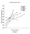
A sensitivity analysis has been carried to find out which parameter may bring out the maximum change in the moment of inertia while there is a minimum increase in the area overall area of the cross section. Each of the parameters were varied while keeping the other remaining five parameters constant. In FIG. 24 the moment of inertia along H-axis (in4) is plotted with the area (in2). In FIG. 23 the ratio between moment of inertia along H-axis and area (in2) is plotted with area (in2). It is observed in both the plots that the contribution towards moment of inertia per unit area (along H-axis) may be the maximum when the length (l) of the cross section is increased. In a separate study it is observed that the moment of inertia per unit area is the maximum when the width (w) of the cross section is increased.
From the above it will be appreciated that to have an optimized shape which has the minimum area, the moment of inertia along the horizontal and vertical axes may be controlled by the respective parameters and all other design parameters f, theta, rce/rcx, t may be kept at a minimum so that they do not contribute towards an increase in area and thus the mass of the structural member.
A wind tower is subjected to bending, substantially normal and torsional loads. The bending loads are high and they govern the design of the leg. The structural shape of the present disclosure is designed so that the two side flanges from the structure act as support for cross bracing and also function as part of the full structural shape in transferring the axial and the bending loads. By designing the side flanges as part of the structural shape the need for separate welded/bolted gussets to the structural leg for attaching bracing is eliminated. This feature reduces the total amount of steel required in a wind tower structure design. In prior leg designs the gussets transfer loads from cross bracing only, and therefore predominantly only utilized for the torsional loads in the tower. It should also be noted that the weld process creates stress foci by changing the nature of the material, usually steel, into a harder but less resilient form. This change in nature can cause laminar force distribution that is typically evenly distributed throughout a structure to concentrate in focused areas as the force refracts due to changes in the nature of the material the force is being transmitted through. Accordingly, a greater amount of homogeny in the the material results in more predictable force distribution, thereby prolonging the life of the structure.
An embodiment may place an emphasis on the length of the side flanges. The side flanges of the present structural shape function as both a structural part of the leg shape and also as the attachment area for the bracing in the tower. The length of the side flanges (dimension f in FIG. 7) should be sufficient to allow enough interface area for the bracing members to bolt or connect. The angle that the bracing approaches the leg may influence the interface area needed on the side flanges but generally the combined cross sectional area of both side flanges should represent about 10%—about 40% or about 20%—about 28% of the total cross sectional area of the present leg structural shape.
An embodiment of a method of design may concentrate on the Constant thickness throughout the cross section. The present structural shape has a constant thickness to allow for multiple fabrication methods that may include cold forming through rolling or break pressing.
An embodiment may employ a method of design focused on a recessed side flange attachments point. The present structural shape is designed so that a line running parallel to the side flange which is tangent to the further most point of the structural shape, maintains a distance equal to about 100% to about 180% or about 140% to about 150% of dimension a of FIG. 7.
Other cross section shapes are possible in addition to that illustrated in FIG. 7. These cross section shapes are illustrated in FIGS. 8-14. FIG. 8 illustrates circular cross section of the framed portion 88 having width w. Flanges 84 may be disposed on either side of the framed portion 88 and may comprise radiused convex or concave portions 89 connecting said flanges 84 with said framed portion 88. The flanges may have length configured to receive various attaching members. The structural member cross sections may be defined by thickness, wherein it may be constant or variable across the cross section.
FIG. 9 illustrates a structural member cross section 90 having a framed portion comprising alternating flat 92 and curved 98 portions. Also illustrated in the cross sectional view are flanges 94 disposed on opposite ends of the framed portion. FIG. 10 illustrates a structural member cross section 100 having convex portion 106 disposed between concave portions 108. The illustrated embodiment may also comprise flanges 104 disposed on opposing ends of the cross section.
FIG. 11 illustrates a structural member cross section comprising assembly of more easily formed shapes, or shaped members that are common in the industry. The embodiment may comprise angular pieces 114, flat pieces 116, and a “c” channel piece forming a framed portion. The components may be assembled in to a structural member on site while erecting a wind tower. The components may also aid in the repair of a wind tower wherein the repair portion of the wind tower may need an unassembled structural member to fit a constrained space.
FIG. 12 illustrates a structural member cross section 120 wherein the radius of the framed portion is defined by “a”, and the flange portion is defined by “b”, and the thickness of the cross section is defined by “t” such that major components of the structural member 120 are defined having an adjustable ratio for fine tuning the structural member 120 for specific loads and applications.
FIG. 13 illustrates a structural member cross section comprising a circular framed portion 138 having flanged portions 134 connected thereto by brackets 136 thereby forming the structural shape 130 comprised of individual components. The embodiment may be defined by separate flange portions 134 such that the flange portions are not made of continuous material but of separate materials. An embodiment may call for different material selections for the components in order to provide flexibility in fine tuning the characteristics of the structural shape 130.
FIG. 14 illustrates an embodiment of a structural member cross section 140 wherein a framed portion 148 and any flanged portions 144 are fabricated from a single kind of material. As discussed above, single kind of material may have homogeneous properties that transfers forces readily there through.
FIG. 15 illustrates a top down cross sectional view of an embodiment of a wind tower 150 showing how a tower comprising five leg members 152 designed a consistent with the structural shape members discussed above. As can be seen in the figure, the leg members are joined by cross members 153 one to another thereby forming a rigid structure with improved structural members having better distribution of forces therein. The angles formed by the components may dictate the number of leg members available for use in the structure. For example, in an embodiment it may be desirable to have a structural tower under a biased load thereby providing increased rigidity within a structural tower.
FIG. 16. Illustrates an embodiment of a profile of cross section of a structural member wherein an angle 162 formed by opposing flanges 164 is determined, such that the number of legs to be used in constructing a wind tower is constrained by the angle 126 formed by the flanges. The equation 180 (N-2)/N may be employed to design the structural members and their characteristics in responding to loads where N is the number of legs in a wind tower design. In the illustrated embodiment for example wherein the desired number of legs is six (6) the equation would be:
Angle=180 (6−2)/6=120 degree angle defined by the flange portions 164. Accordingly a tower made of six legs would comprise legs made up of structural members have 120 degree angles defined by the flanges of the structural member.
FIG. 17 illustrates an embodiment of cross section of a structural member 170 having a varying thickness 179 of material throughout the cross section. A variable thickness may provide the advantage of fine tuning structural members to respond to a specific loading within a tower structure. Additionally, variable thickness may provide low manufacturing costs by allowing or accommodating deformation of the material during the forming process. For example: during roll forming, cold or thermal aided, uniformity of composition of the material being worked may be imperfect thereby resulting in some inconsistent thickness along the cross section 170 as illustrated in the figure. An embodiment of a structural member may have a cross sectional shape designed to compensate for the short comings of some forming processes. In other words, a structural member may be designed wherein inconsistencies are allowed to form is less tolerance critical portions so that more tolerance critical portions of the structural shape may be preserved with tighter tolerances.
In an embodiment a second forming process may be employed to provide a more precise tolerance wherein after a first process has been performed such as roll forming, a second process employing a press brake may be performed on the structural member to further and more precisely shape the structural member. The embodiment may further allow non-uniformity at various cross sections along the length of the structural member in a predictable manner such that the refining process of the press break can be employed in a more uniform fashion from one structural member to the next structural member.
In an embodiment multiple press brake processes may be employed in succession or assembly line fashion to form a structural member. For example, a first press brake process may form a first deformation or bend in a material, the deformed piece is then changed in orientation relative to the press brake, a second press brake process may then be performed causing a second deformation of the piece. An embodiment of a structural member having n number of flat portions separated by m number of curved portions may require n+m processes to fully form a structural member. Alternatively, flat material stock may only require m number of processes as the flat portions plus flanges are derived from the original flatness of the raw material.
FIG. 18 illustrates an embodiment of cross section of a structural member 180 wherein opposing flanges 184 form an angle A in the range of 100 degrees to 130 degrees. Also illustrated in the embodiment is dimension “a” that represents the allowable width of any connecting members thereby allowing cladding to be placed around the tower.
It is a well known fact that inertia increases as the mass is distributed away from the centroid and decreases as the distribution of mass is closer to the centroid. An analysis of different cross sections reveals that the present disclosure cross section has the greatest distribution of mass away from the centroid and so this is the optimum design.
The inertia of the different shapes is kept as a constant to compare the different areas of different cross sections. This feature enables quantification of the proportionate increase in area. For a fixed inertia I1 along axis 1 and inertia 12 along axis 2 for area A for the present disclosure leg the areas for other cross sections are illustrated in Table A below. For each shape the following optimization rule was applied and typical design limits were set as constraints such as Minimize area while constraining the other variables to:
Ix=Iy is at least 3500 in4
Max distance from centroid=12 in.
TABLE A
Area for different shapes.
Shape Area
Present Disclosure   1 A
Current (prior art) 1.56 A
Leg
Semi circular 1.32 A
V-shape 2.43 A
Angle cross section 1.81 A
The dimensions that are needed to define the different cross sections are illustrated in FIG. 12. A main difference between the present disclosure structure and other cross sections is that the present disclosure structure provides more control in distributing the material away from the centroid providing a larger number of parameters or options for defining the shape of the cross section. Also the moment of inertia of each shape is arrived by dividing the cross section into regular shapes which have pre-defined moment of inertia values. Table B below illustrates the number of regions and the number of dimensions for each shape. Of the shapes explored, the present disclosure cross section has the maximum number of regions and dimensions to define.
TABLE B
Dimensions and number of regions in each cross
section.
Shape Dimensions No. Regions
Structural Member 5 3
Current (Prior Art) Leg 3 1
Semi circular 3 3
V-shape 2 2
Angle cross section 3 4

As can be seen in the table the disclosed structural member provides increased options for providing a structural member having a cross sectional shape and area that can be fine tuned for any given application by simply varying the appropriate variable or dimension that characterizes the structural member.
FIG. 19 illustrates the joining or splicing of two structural members in the formation of a wind tower leg in a space frame wind tower. Splicing allows for the connection of a first structural member 191 to be placed upon a second structural member 192 thereby forming a leg or leg segment 190. After aligning the first and second structural members, splicing or connecting plates 195 may be used to splice the structural members together. The connecting plates 195 may be paired so as to provide a pressure fit such that the spliced ends of the structural members are sandwiched between the connecting plates 195. A fastener 197 having a secondary component 196 may be used to provide the fastening of the spliced components. The fasteners 197 may be of interference fit type. A standard bolt nut combination may also be used. In an embodiment of an assembly method a user may first use a common bolt and nut combination to first align the splicing components and then replace said bolt and nut combination with interference fit fasteners that are more wear resistant.
FIG. 20 illustrates the joining or splicing of two structural members in the formation of a leg in a space frame wind tower. Splicing allows for the connection of a first structural member 201 to be placed upon a second structural member 202 thereby forming leg portion 200. After aligning the first and second structural members splicing or connection plates 204 and 206 may be used to splice the structural members together. The connection plates 204 and 206 may be paired so as to provide a pressure fit such that the spliced ends of the structural members sandwiched between the connecting plates 204 and 206. The present embodiment illustrates a connecting plate having a profile similar to the profile of the structural members. A fastener 208 having a secondary component 209 may be used to provide the fastening of the spliced components. The fastener 208 may be of interference fit type. A standard bolt and nut combination may also be used. In an embodiment of an assembly method a user may first use a common bolt and nut combination to first align the splicing components and then replace said bolt and nut combination with interference fit fasteners that are more wear resistant.
FIG. 21 illustrates the joining or splicing of two structural members in the formations of a leg in a space frame wind tower. Splicing allows for the connection of first structural member 211 to be placed upon second structural member 212 thereby forming a leg portion 210. After aligning the first and second structural members, splicing or connecting end plates 214 and 213 may be fitted and attached to the facing end portions of the first and second structural members and are then used to splice the structural members together. The connecting end plates 213 and 214 may be paired so as to provide pressure fit such that the spliced ends of the structural members abut one another. The present embodiment illustrates connecting end plates having a channel with profile similar to the profile of the structural members so as to receive the end of the structural members therein. A fastener 216 having a secondary component 217 may be used to provide the fastening of the splicing components. A fastener 219 and a secondary fastener component 218 may be used to a affix the connecting end plates to the respective structural members. The fasteners may be of interference fit type. A standard bolt and nut combination may also be used. A shim 215 may be employed between said first and second structural member ends thereby providing some adjustability in the leg construction in order to provide alignment of the wind tower during construction. The shim 215 may also be composed of a material with predetermined properties so as to reduce forces transmitted throughout the wind tower such as a dampening feature. In an embodiment of an assembly method a user may first use common bolt and nut combination to first align the splicing components and then replace said bolt and nut combination with interference fit fasteners that are more wear resistant.
FIG. 22 illustrates the joining or splicing of two structural members in the formation of a leg in a space frame wind tower. Splicing allows for the connection of a first structural member 221 to be placed upon a second structural member 222 thereby forming a leg portion 220. In the present embodiment the first and second structural members have ends 221 a and 222 a respectively formed thereon. After aligning the first and second structural members, ends 221 a and 222 a are affixed with fastener 225. A fastener 225 having a secondary component 224 may be used to provide the fastening of the splicing components. The fasteners may be of interference fit type. A standard bolt nut combination may also be used. A shim 223 may be employed between the first and second structural member ends thereby providing some adjustability in the leg construction in order to provide alignment of the wind tower during construction. The shim 223 may also be composed of a material with predetermined properties so as to reduce forces transmitted throughout the wind tower common bolt and nut combination to first align the splicing component and then replace said bolt and nut combination with interference fit fasteners that are more wear resistant.
Illustrated in FIGS. 23 and 24 an embodiment of the present disclosure may be formulated to optimize the cross sectional area and torsional rigidity. In the design approach, one may determine what would be the required moment of inertia along the horizontal and vertical axis of the cross section. The next step may be to determine the thickness of the cross section of a structural member. This is governed by the bearing loads in the bolted connections and the potential for buckling. The radius of curvature has a lower limit which depends on the thickness. The width of the shape has a lower limit which depends on the minimum gap required to work within the boundary of the shape with tools to tighten the bolted connections between leg members. A sensitivity analysis was carried to find out which parameter brings out the maximum change in moment of inertia while there is minim increase in the area. Each of the parameters was varied while keeping the other five parameters held constant.
In FIG. 23 the ratios between moment of inertia and the area are plotted along the vertical axis while the area of the cross section is plotted on the horizontal axis. It is observed in the plots that the contribution towards moment of inertia per unit area (along H axis) is the maximum when the length of the cross section is increased. In a separate study it is observed that the moment of inertia per unit area (along V axis) is the maximum when the width of the cross section is increased. From the above it will be appreciated to that to have an optimized shape which has the minimum area, the moment of inertia along the horizontal (along H axis) and vertical axes (along the V axis) may be controlled by the respective parameters and all other design parameters may be kept at a minimum so that they do not contribute towards an increase in area. Beyond optimizing a structural shape for inertia and cross-sectional area, other design parameters may also be considered. Length of the side flanges-the side flanges of the present structural shape function as both a structural part of the leg shape and also as the attachment area for the bracing in the tower. The angle that the bracing approaches the leg will influence the interface area needed on the side flanges but generally the combined cross sectional area of both side flanges should represent about 40% of the total cross sectional area of the present leg structural shape.
FIG. 24 represents graphically an analysis of different cross sections revealing that the present disclosure cross section has the greatest distribution of mass away from the centroid and so this is the optimum design. The inertia of the different shapes is kept as a constant to compare the different areas of different cross sections. This feature enables quatinfication of the proportionate increase in area.
FIG. 25 illustrates a method 250 for splicing structural members together thereby forming a leg. At 215 a user aligns a first structural member with a second structural member at their respective ends. At 253 a user aligns a joiner such that it spans the aligned ends of the first and second structural members. At 255 a user fastens the joiners to the first and second structural members with a fastener as described above. Joiners may be of splicing plates and connectors described above with regard to FIGS. 19 and 20. Joiners may be a joiner structure that is affixed or a continuation of the structural member as illustrated in FIGS. 21 and 22. An embodiment of a related method may include the process of fastening the component first with common fasteners that allow for some tolerance for adjustments and then performing a second process of removing the common fasteners one at a time. Once the common fastener is removed an engineered fastener, such as an interference fit fastener may be used to provide increased wear resistance.
FIG. 26 illustrates a method 260 for splicing structural members together thereby forming a leg. At 261 a user aligns a first structural member with a second structural member at their respective ends. At 253 a user aligns the leg structural members by shimming spliced structural members. At 265 a user aligns a joiner such that it spans the aligned ends of the first and second structural members and the shims. At 267 a user fastens the joiner to the first and second structural members with a fastener as described above. Joiners may be of the splicing plates and connectors described above with regard to FIGS. 19 and 20. Joiners may be a joiner structure that is affixed or a continuation of the structural member as illustrated in FIGS. 21 and 22. An embodiment of a related method may include the process of fastening the components first with common fasteners that allow for some tolerance for adjustment and then performing second process of removing the common fasteners one at a time. Once the common fastener is removed an engineered fastener, such as an interference fit fastener may be used to provide increased wear resistance.
With reference to FIGS. 27-33 a method of constructing a tower will be discussed in great detail, including structures that will be used in constructing a tower using structural members with the present disclosure. Referring to FIG. 27 the portions of a structural member will be discussed. FIG. 27 is a cross sectional view of a structural member 270 having a pair of wings or flange faces 274, a pair of side faces 276, and a front face 278.
Illustrated in FIG. 28 is an example of a tool used to install and tighten the drive pins that may be hand held and may be pneumatic and may include a reaction arm. The tool used may have a minimum rated torque capacity of 2000 ft., lbf. In addition, the tooling may be subject to the dimensional constraints defined structure member dimensions as shown in the diagram.
Pre-assembled tower sections can be installed with crawler cranes. The splice plates may generally be bolted to the section top. The section may be hooked to the crane with cables and is lifted and placed on the tower. The steps illustrated below apply for all the legs in the tower. With reference to FIG. 29 a foundational structural member 310 will be discussed. Foundation splice plates 312 and 313 may be attached to the tower leg member 310 before the leg member is set on the foundation anchors. In use a user would place an inside front splice plate 312 against the inside front face at the bottom end of the leg member 310 and align the fastening holes therein. The user may then insert drive pins 314 into holes in the splice plate 312 such that the head of the drive pin 314 is on the inside of the tower leg. User then may place one washer 316 over exposed thread of drive pin 314 and hand tighten a temporary heavy hex nut onto each drive pin 314. Using the provided pneumatic tool discussed above, a user may tighten the temporary nut until the drive pin has been pulled into engagement with the splice plate 312 and the leg member 310. The user should then remove the temporary nuts 315 and the washers 316. The user may then place the outside front splice plate 313 over the drive spins 314 that are protruding from the front face of the tower leg 310. Place one washer 316 and then read one nut 315 onto each drive pin 314 as shown in the figure. The user should then use the provided pneumatic tool to tighten the nuts. Referring now to FIG. 29 the splicing of structural members will be discussed. In a first structural member 320 place a splice plate on the outer side of the front face, side and wing faces inches from the structural member 320 and insert two long bolts 325 through each plate 322. The long bolts 325 go through holes in the front face, and in the side face, and in the flange face. Place another set of splice plates 322 inches away front the structural member on the inner side of all the faces so that long bolts 325 pass through the corresponding bolt holes in the respective faces. The head of the bolt 325 is in the outside face. Insert a nut 327 on all the bolts 325.
A second structural member 326 aligned with the first structural member 320 and splice plates 324 and 322. The user may then tighten the long bolts 327 with the recommended pneumatic tool until all the splice plate 322 and 324 on the inside and outside of the front face, side and wing faces mate with the structural member surfaces as can be seen in FIG. 30. It should be noted that the splice plates may be used to align the structural members such that the legs can be adjusted during construction as indicated by and in the figure. A user may then place drive pins 328 in any remaining holes and tighten to the specification prescribed as shown in FIG. 31.
With reference to FIG. 32 the attachment of a tower top ring 380 at the top of a structural tower will be discussed. A user may attach a tower top ring 380 to the upper most portion of a structural member 370 by use of a center bracket 376, side bracket 377 and drive pin fasteners 375. A user may first align the side bracket 377 to the bolt holes of the structural member 370 and the center bracket in the side face 276.
The user may then insert drive pins 375 through the holes in the side face 276 and brackets 377 and 376 thereby attaching the brackets to the structural member 370. A user should then use a measuring device to check if there is a difference in elevation between the top surfaces of flanges from each of a plurality of the legs. The user may then use shim plates to raise the top of any leg flange which is lower in elevation. The difference in elevation is compared to legs whose flanges have the highest top surface. Once the brackets have been leveled a user may place the tower top ring 380 on the flanges and make sure that the bolt holes in the ring align with the bolt holes in the top surface of the flanges and the shims. The user should then insert the fasteners or drive pins 375 and tighten to a specified torque thus completing the tower structure.
With a reference to FIG. 33 a cross-section of a structural member will be discussed. The structural member may comprise a frame portion 402 and flange portions 404. It may be desirable to control or minimize the spring constant K of a structural member. In an embodiment the angle indicated by D in the illustration may be between 95 degrees to 140 degrees. By increasing angle D in the framed portions 402 the plane frame portion sides are put into direct conflict with the plane of deflection experienced by the structural member, thereby greatly increasing the structural rigidity and spring constant of a tower leg. By modifying the angle D a structural member may be tuned for specific applications. It should be noted also that by increasing the angle, more room is provided within the member thus allowing for greater tool use options.
While the cross sectional shape of a structural member for use in a tower leg may be optimized with the principles of the disclosure thus far, additional stiffness or simply deformation resisting support may be desired. This deformation resisting support can be implemented in a variety of configurations several of which are disclosed herein.
If additional stiffness is desired or needed at infrequent intervals throughout a structural member, a cross section brace may be employed for providing additional support as illustrated in FIG. 34. The cross section brace 348 may be incorporated into a structural member 340. The structural member 340 will also comprise flange portions 344 that may be configured to offer additional strength and also provide attaching means for lattice structures. The cross section brace 348 may span a portion of the frame portion 342 of the structural member 340 and may comprise end extensions for bracing the flange portions 344.
FIG. 35 illustrates an embodiment of a structural member 350 that has been equipped with additional supports throughout. The cross section brace 358 may be incorporated into a structural member 350. The structural member 350 will also comprise flange portions 354 that may be configured to offer additional strength and also provide attaching means for lattice structures. The cross section brace 358 may span a portion of the frame portion 352 of the structural member 350 and may comprise end extensions for bracing the flange portions 354. The embodiment shows additional flat bracing members 359 that may be added to the structural member 350.
FIG. 36 illustrates an embodiment of a structural member 360 that has been equipped with additional supports throughout. The cross section brace 368 may be incorporated into a structural member 360. The cross sectional brace 368 may be formed from a C shape that spans at least a portion of the frame portion 362 of the structural member 360. The structural member 360 will also comprise flange portions 364 that may be configured to offer additional strength and also provide attaching means for lattice structures. The cross section brace 368 may span a portion of the frame portion 362 of the structural member 360 and may comprise end extensions for bracing the flange portions 364. The embodiment shows additional flat bracing members 369 that may be added to the structural member 360.
FIG. 37 illustrates an embodiment of a structural member 370 that has been equipped with additional supports throughout. The cross section brace 378 may be incorporated into a structural member 370. The structural member 370 will also comprise flange portions 374 that may be configured to offer additional strength and also provide attaching means for lattice structures. The cross section brace 378 may span a portion of the frame portion 372 of the structural member 370 and may comprise attaching means for attaching the brace to the flange portions 374.
FIG. 38 illustrates and embodiment of a structural member 380 that has been equipped with additional support. The cross section brace 388 may be incorporated into a structural member 380. The structural member 380 will also comprise flange portions 384 that may be configured to offer additional strength and also provide attaching means for lattice structures. The cross section brace 388 may span a portion of the frame portion 382 of the structural member 380 and may comprise end extensions for bracing the flange portions 384. A cross section brace may be positioned for possible local stress and deformation reduction. The cross section brace may be formed of bent steel plate that can either be the full length of the tower leg or can be localized to shorter lengths. There are multiple ways to attach the cross section brace and multiple shapes. Attachment methods considered may be bolting the plate to both of the flanges or bolting the cross section brace to inner walls of the shape where interface with the flanges does not have to occur. An embodiment may use welding of the cross section brace to the structural member. An embodiment may utilize mechanical interface to connect one side of the cross section brace while bolting the opposite side to the opposite the other side. The cross section brace may be shaped to maximize the moment of inertia of the combined shape of the structural member and the cross section brace. The cross section brace which is localized may readily be applied at each of the structural member splicing points along the tower leg and can also readily be used at the tower leg to tower leg joints of a tower. At these leg-to-leg joints the cross section brace can either be utilized near the end of each leg or the cross section brace can also be used as a leg-to-leg splice plate thereby spanning from one leg to the next as it is joined to both.
It is to be understood that the above-described arrangements are only illustrative of the application of the principles of the present disclosure. Numerous modifications and alternative arrangements may be devised by those skilled in the art without departing from the spirit and scope of the present disclosure and the appended claims are intended to cover such modifications and arrangements. Thus, while the present disclosure has been shown in the drawings and described above with particularity and detail, it will be apparent to those of ordinary skill in the art that numerous modifications, including, but not limited to, variations in size, materials, shape, form, function and manner of operation, assembly and use may be made without departing from the principles and concept set forth herein.
In the foregoing Detailed Description, various features of the present disclosure are grouped together into single embodiments for the purpose of streamlining the disclosure. This method of disclosure is not to be interpreted as reflecting an intention that the claimed disclosure requires more features than are expressly recited in each claim. Rather, as the following claims reflect, inventive aspects lie in less than all features of a single foregoing disclosed embodiment. Thus, the following claims are hereby incorporated into this Detailed Description by this reference, with each claim standing on its own as a separate embodiment of the present disclosure.
It is to be understood that the above-described arrangements are only illustrative of the application of the principles of the present disclosure. Numerous modifications and alternative arrangements may be devised by those skilled in the art without departing from the spirit and scope of the present disclosure and the appended claims are intended to cover such modifications and arrangements. Thus, while the present disclosure has been shown in the drawings and described above with particularity and detail, it will be apparent to those of ordinary skill in the art that numerous modifications, including, but not limited to, variations in size, materials, shape, form, function and manner of operation, assembly and use may be made without departing from the principles and concepts set forth herein.

Claims (49)

What is claimed is:
1. A wind tower comprising:
a plurality of legs, each of said plurality of legs comprising a structural member, said structural member having an open cross section defining a substantially unobstructed inner surface facing toward a midpoint of the tower, said open cross section comprising:
two flange portions for attaching said structural member into said wind tower,
a framed portion connecting said flange portions so as to define an outermost cavity of said structural member, wherein said cavity extends radially outward from the midpoint of the tower, and
wherein said flange portions and said framed portion are extended substantially normal to the open cross section thereby forming said structural member.
2. The wind tower of claim 1, at least four legs comprising said structural members.
3. The wind tower of claim 2, said structural members further comprising a joining structure disposed thereon for joining.
4. The wind tower of claim 1, five legs comprising said structural members.
5. A space frame wind tower comprising:
a plurality of legs, each of said plurality of legs comprising a structural member, said structural member having an open cross section defining a substantially unobstructed inner surface facing toward a midpoint of the tower, said open cross section comprising:
two flange portions for attaching said structural member into said wind tower,
a framed portion connecting said flange portions so as to define an outermost cavity of said structural member, wherein said cavity extends radially outward from midpoint of the tower, and
wherein said flange portions and said framed portion are extended substantially normal to the open cross section thereby forming said structural member.
6. The space frame wind tower of claim 5, wherein the structural member further comprises a flat portion.
7. The space frame wind tower of claim 6, wherein said flat portion is disposed between a convex portion and a concave portion.
8. The space frame wind tower of claim 7, wherein said concave portion is adjacent to one of the flange portions.
9. The space frame wind tower of claim 7, wherein the concave portion has a radius of curvature that is less than 5 times the thickness but greater than a thickness of any portion of the cross section.
10. The space frame wind tower of claim 7, wherein the convex portion has a radius of curvature that is equal to or greater than a thickness of any portion of the cross section.
11. The space frame wind tower of claim 6, wherein said flat portion is disposed between said flange portions.
12. The space frame wind tower of claim 5, wherein the structural member further comprises a plurality of flat portions.
13. The space frame wind tower of claim 5, wherein the ratio between moment of inertia and the area of the cross section is in the range from about 25 to about 300 in4.
14. The space frame wind tower of claim 5, wherein the moment of inertia is in the range from about 800 to about 10000 in4.
15. The space frame wind tower of claim 5, wherein the moment of inertia is in the range from about 1500 to about 4500 in4.
16. The space frame wind tower of claim 5, wherein the area of the cross section is in the range from about 30 to about 210 in2.
17. The space frame wind tower of claim 5, wherein the area of the cross section is in the range from about 50 to about 110 in2.
18. The space frame wind tower of claim 5, wherein the cross section is asymmetric.
19. The space frame wind tower of claim 5, wherein the cross section is symmetric about an axis.
20. The space frame wind tower of claim 5, wherein the structural member is formed by more than one segment bonded together by a fastener across the length of the cross section.
21. The space frame wind tower of claim 5, wherein the structural member is formed by just one continuous piece of material.
22. The space frame wind tower of claim 5, wherein the length of the flange portions is between about 15% to about 25% of the total perimeter of the cross section.
23. The space frame wind tower of claim 5, wherein the length of the flange portions is substantially about 10% to about 15% of the total perimeter of the cross section.
24. The space frame wind tower of claim 5, wherein the angle between the flanges is dependent on the number of legs to be used in the wind tower structure.
25. The space frame wind tower of claim 5, wherein the angle between the flanges is the product of 180 degrees multiplied by the number of legs to be in the final tower structure minus two; and wherein the product is then divided by two multiplied by the number of legs to be in the final tower.
26. The space frame wind tower of claim 5, wherein the ratio between the width of the cross section and the perimeter of the frame portion is within the range from about 0.8 to about 0.2.
27. The space frame wind tower of claim 5, wherein the ratio between the width of the cross section and the perimeter of the frame portion is substantially about 0.7 to about 0.35.
28. The space frame wind tower of claim 5, wherein said structural member further comprises a brace spanning at least a portion of said framed portion.
29. The space frame wind tower of claim 5, wherein the thickness of the cross section is in the range from about 0.25 to about 1.125 in.
30. The space frame wind tower of claim 5, wherein the thickness of the cross section is in the range from about 0.375 to about 1 in.
31. The space frame wind tower of claim 5, wherein the thickness of the cross section is in the range from about 0.4375 to about 0.875 in.
32. The space frame wind tower of claim 5, wherein the ratio of the thickness and the perimeter of cross section is in the range from about 0.005 to about 0.03 in.
33. The space frame wind tower of claim 5, wherein the ratio of the thickness and the perimeter of cross section is in the range from about 0.005 to about 0.02 in.
34. The space frame wind tower of claim 5, wherein the thickness of the cross section is constant along the length of the leg.
35. The space frame wind tower of claim 5, wherein the thickness of the cross section varies along the length of the leg.
36. The space frame wind tower of claim 5, wherein an angle formed between said flange portion and said frame portion ranges between about 80 degrees and about 175 degrees.
37. The space frame wind tower of claim 5, wherein the structural member further comprises a brace wherein said brace comprises a first end and a second end and wherein said first end is affixed to a flange and wherein said second end is attached to another flange.
38. The space frame wind tower of claim 37, wherein said brace is affixed to said framed portion.
39. The space frame wind tower of claim 5, wherein the structural member has the ratio between the depth dimension, length (l), of the shape and the perimeter of the box shaped frame as about 0.5>(l/box perimeter)>about 0.15.
40. The space frame wind tower of claim 5, wherein the structural member has the ratio between the depth dimension, length (l), of the shape and the perimeter of the box shaped frame as about 0.35>(l/box perimeter)>about 0.2.
41. The space frame wind tower of claim 5, wherein the outer perimeter of the cross section is in the range from about 50 to about 130 in.
42. The space frame wind tower of claim 5, wherein the outer perimeter of the cross section is in the range from about 50 to about 100 in.
43. The space frame wind tower of claim 5, wherein the structural member is made of a metal.
44. The space frame wind tower of claim 5, wherein the structural member is fabricated by a metal forming process.
45. The space frame wind tower of claim 44, wherein the structural member is fabricated out of a steel plate using a press brake forming process.
46. The space frame wind tower of claim 44, wherein the structural member is fabricated out of coil using a press brake forming process.
47. The space frame wind tower of claim 44, wherein the structural member is fabricated out of steel plate using a cold roll forming process.
48. The space frame wind tower of claim 44, wherein the structural member is fabricated out of coil using a cold roll forming process.
49. A wind tower comprising:
a structural member for use in constructing a wind tower comprising, wherein said structural member comprises an open cross section defining a substantially unobstructed inner surface facing toward a midpoint of the tower, wherein said structural member forms a framed portion and flange portions, wherein the framed portion defines an outermost cavity of said structural member, wherein said cavity extends radially outward from a midpoint of the tower, wherein the framed portion and flange portions are extended substantially normal to a cross section of said structural member:
means for attaching other structures to said structural member for constructing a lattice thereby forming said wind tower;
means for resisting compressive loading for preserving the structural integrity of said wind tower; and
means for resisting torsional loading for preserving the structural integrity of said wind tower.
US12/638,982 2008-12-15 2009-12-15 Structural shape for wind tower members Expired - Fee Related US8910446B2 (en)

Priority Applications (2)

Application Number Priority Date Filing Date Title
US12/638,982 US8910446B2 (en) 2008-12-15 2009-12-15 Structural shape for wind tower members
US14/563,037 US20150152851A1 (en) 2008-12-15 2014-12-08 Structural shape for wind tower members

Applications Claiming Priority (3)

Application Number Priority Date Filing Date Title
US12259308P 2008-12-15 2008-12-15
US16385709P 2009-03-26 2009-03-26
US12/638,982 US8910446B2 (en) 2008-12-15 2009-12-15 Structural shape for wind tower members

Related Child Applications (1)

Application Number Title Priority Date Filing Date
US14/563,037 Division US20150152851A1 (en) 2008-12-15 2014-12-08 Structural shape for wind tower members

Publications (2)

Publication Number Publication Date
US20100242406A1 US20100242406A1 (en) 2010-09-30
US8910446B2 true US8910446B2 (en) 2014-12-16

Family

ID=42288090

Family Applications (2)

Application Number Title Priority Date Filing Date
US12/638,982 Expired - Fee Related US8910446B2 (en) 2008-12-15 2009-12-15 Structural shape for wind tower members
US14/563,037 Abandoned US20150152851A1 (en) 2008-12-15 2014-12-08 Structural shape for wind tower members

Family Applications After (1)

Application Number Title Priority Date Filing Date
US14/563,037 Abandoned US20150152851A1 (en) 2008-12-15 2014-12-08 Structural shape for wind tower members

Country Status (8)

Country Link
US (2) US8910446B2 (en)
EP (1) EP2376726A4 (en)
CN (1) CN102369331B (en)
AU (1) AU2009330323B2 (en)
BR (1) BRPI0917769A2 (en)
CA (1) CA2746880A1 (en)
MX (1) MX337407B (en)
WO (1) WO2010075117A1 (en)

Cited By (4)

* Cited by examiner, † Cited by third party
Publication number Priority date Publication date Assignee Title
US20150316035A1 (en) * 2012-11-01 2015-11-05 Marmen Inc. Wind turbine tower assembly
CN106294917A (en) * 2015-06-10 2017-01-04 中国电力科学研究院 A kind of adjustment method of the column foot plate of power transmission tower
US20170248126A1 (en) * 2014-10-06 2017-08-31 Vestas Wind Systems A/S Hinged tower segments and transport method
US10167634B2 (en) * 2016-06-10 2019-01-01 Christie Lites Enterprises Canada Inc. Truss section connection apparatus

Families Citing this family (17)

* Cited by examiner, † Cited by third party
Publication number Priority date Publication date Assignee Title
DE102007039957A1 (en) * 2007-08-23 2009-02-26 Seeba Technik Gmbh triangular profile
US20110133475A1 (en) * 2010-04-23 2011-06-09 Danian Zheng Support tower for use with a wind turbine and system for designing support tower
US8196358B2 (en) * 2010-08-25 2012-06-12 Mitsubishi Heavy Industries, Ltd. Wind turbine generator tower
US8209913B2 (en) * 2011-02-01 2012-07-03 Mitsubishi Heavy Industries, Ltd. Tubular structure and wind turbine generator
US8881485B2 (en) * 2011-05-23 2014-11-11 Iowa State University Research Foundation, Inc. Wind turbine tower system
US8915043B2 (en) 2011-05-25 2014-12-23 General Electric Company Bolt connection for a wind tower lattice structure
DK2551519T3 (en) * 2011-07-27 2015-11-16 Siemens Ag Optimization of a wind power plant
US8393118B2 (en) 2011-12-22 2013-03-12 General Electric Company Friction damping bolt connection for a wind tower lattice structure
CN105121759B (en) * 2013-02-01 2018-03-27 赛克圣诺巴西有限公司 Truss-like tower
ES2799349T3 (en) * 2014-03-04 2020-12-16 Nabrawind Sl Connection between lattice tower and gondola
EP2944810A1 (en) * 2014-05-15 2015-11-18 Rambøll Danmark A/S A wind turbine tower part and use of a wind turbine tower part
MX2019003207A (en) 2016-09-21 2020-07-21 Skyrise Global Llc Structure and method of making the same.
BR112019027895B1 (en) * 2017-06-30 2023-11-07 Arcelormittal MAST SECTION FOR A WIND TURBINE, WIND TURBINE MAST AND METHOD FOR MOUNTING A MAST SECTION
CN107386759A (en) * 2017-07-11 2017-11-24 深圳带路科技有限公司 A kind of bamboo shape steel tower bracing means
CN110761954B (en) * 2019-11-19 2024-01-19 中国电建集团西北勘测设计研究院有限公司 Precast concrete fan tower barrel with spiral line connecting seam and connecting method
CN112922785B (en) * 2021-01-08 2022-08-02 张家口大金风电装备有限公司 Truss type tower and wind generating set
US20230139715A1 (en) * 2021-05-22 2023-05-04 Ashraf Radi Reinforcing of Solid Round Legs in Telecom Towers

Citations (131)

* Cited by examiner, † Cited by third party
Publication number Priority date Publication date Assignee Title
US877587A (en) 1906-07-20 1908-01-28 La Verne W Noyes Skeleton tower.
US889395A (en) 1905-07-13 1908-06-02 La Verne W Noyes Tower.
US1506984A (en) 1921-04-07 1924-09-02 Blaw Knox Co Tower and other similar structure
US1626393A (en) 1924-03-10 1927-04-26 William H Cater Frame structure
US1870914A (en) 1929-02-11 1932-08-09 Lane Frank Sheet metal structure
GB408828A (en) 1932-06-27 1934-04-19 Heinrich Toussaint Improved profiled iron
US2014784A (en) 1933-07-11 1935-09-17 Int Stacey Corp Wave antenna
US2135631A (en) 1936-12-21 1938-11-08 Ernest G Amesbury Portable apparatus for transferring loads
US2145232A (en) 1937-06-24 1939-01-31 Missouri Rolling Mill Corp Steel tower member
US2246151A (en) 1939-05-24 1941-06-17 Locke Insulator Corp Tower antenna
US2756952A (en) 1952-06-21 1956-07-31 Cleveland Pneumatic Tool Co Omni-directional shock and vibration isolating device
US2945231A (en) 1958-05-12 1960-07-12 Andrew Corp Communication antenna
US2950576A (en) 1956-04-25 1960-08-30 Rubenstein David Shock absorbing connections for building constructions
US3079277A (en) 1959-11-16 1963-02-26 Lord Mfg Co Damped structure
US3100555A (en) 1961-10-16 1963-08-13 Youngstown Sheet And Tube Co Plastic tower
US3119471A (en) 1959-04-02 1964-01-28 Rohn Mfg Co Tower structure
GB1008782A (en) 1961-07-15 1965-11-03 Liebig Heinrich Cylindrical-spread anchor-bolt
US3219214A (en) 1962-05-02 1965-11-23 Bucyrus Erie Co Excavator dipper door mounting
US3276762A (en) 1964-10-28 1966-10-04 Edward V Thomas Omnidirectional damped support member
US3277614A (en) 1962-10-08 1966-10-11 Pierre Georges Robert Pneumatic girders and frameworks
US3353854A (en) 1965-04-09 1967-11-21 Gen Electric Structural corner assembly
US3371458A (en) 1966-06-30 1968-03-05 Atlantic Res Corp Structural unit
US3456972A (en) 1967-02-27 1969-07-22 Ford Motor Co Fastened assembly having a high resistance to varying shear loads
US3485005A (en) 1966-10-10 1969-12-23 Jacob H Kutchai Structural assembly
US3561711A (en) 1969-07-02 1971-02-09 Dwight V Dodge Portable tower
US3574982A (en) 1967-12-19 1971-04-13 Waagner Biro Ag Installation for one or more stacks
US3618928A (en) 1969-08-14 1971-11-09 Paul H Taylor Resilient cylinder liquid spring
US3634989A (en) 1970-01-19 1972-01-18 Cyril B Rogers Modular tower
US3650078A (en) 1970-09-15 1972-03-21 Economy Forms Corp Shore tower assembly
US3650081A (en) 1970-09-17 1972-03-21 Economy Forms Corp Shore tower assembly
US3659490A (en) 1969-08-27 1972-05-02 Harold G Buck Fastening device
US3710674A (en) 1970-12-18 1973-01-16 Meteor Res Ltd Expandable fastener
US3742662A (en) 1971-08-05 1973-07-03 Hursh Jack E Millbrae Shoring frame system
US3747695A (en) 1971-04-06 1973-07-24 Pyramid Derick And Equipment C High floor pivoted mast drilling rig
US3763617A (en) 1972-04-03 1973-10-09 C M H Inc Tieback apparatus
US3812771A (en) 1971-12-21 1974-05-28 Mitsubishi Heavy Ind Ltd Steel-tower chimney
US3892398A (en) 1972-06-14 1975-07-01 Firestone Tire & Rubber Co Compression spring
US3924056A (en) 1973-12-13 1975-12-02 James T Locicero Slotted masonry wall structure and metal stud therefor
US3939988A (en) 1969-04-09 1976-02-24 General Crane Industries Limited Tower crane
US4039050A (en) 1969-05-13 1977-08-02 Monsanto Company Damping system
US4226554A (en) 1978-05-23 1980-10-07 Massachusetts Institute Of Technology Method and apparatus for absorbing dynamic forces on structures
US4254847A (en) 1978-07-24 1981-03-10 Houdaille Industries, Inc. Rubber viscous torsional dampers and method of making same
US4261441A (en) 1979-05-07 1981-04-14 Daf Indal Ltd. Wind turbine damper
US4272929A (en) 1979-08-23 1981-06-16 Hanson Bror H Tower and method of construction
US4278726A (en) 1978-09-28 1981-07-14 N. V. Bekaert S.A. Energy absorbing elements comprising rigid non-elastomeric layer and visco-elastic layer with twisted fiber bundles embedded therein
US4297076A (en) 1979-06-08 1981-10-27 Lockheed Corporation Wind turbine
US4311434A (en) 1980-04-07 1982-01-19 Agency Of Industrial Science & Technology Wind turbine
US4312162A (en) 1979-08-15 1982-01-26 Jonas Medney Reinforced pole
US4320602A (en) 1979-01-17 1982-03-23 Richardson John R Stabilizing structures against oscillation
US4403916A (en) 1980-09-02 1983-09-13 Chicago Province Of The Society Of Jesus Wind turbines
US4406558A (en) 1979-12-22 1983-09-27 Richard Kochendorfer Gudgeon pin
US4411114A (en) 1980-12-29 1983-10-25 M.A.N. Maschinenfabrik Augsburg-Nurnberg Aktiengesellschaft Compression-tension strut
US4420692A (en) 1982-04-02 1983-12-13 United Technologies Corporation Motion responsive wind turbine tower damping
US4435647A (en) 1982-04-02 1984-03-06 United Technologies Corporation Predicted motion wind turbine tower damping
US4457500A (en) 1981-05-19 1984-07-03 Messerschmitt-Boelkow-Blohm Gesellschaft Mit Beschraenkter Haftung Bending spring made of fiber compound material
US4515525A (en) 1982-11-08 1985-05-07 United Technologies Corporation Minimization of the effects of yaw oscillations in wind turbines
US4565929A (en) 1983-09-29 1986-01-21 The Boeing Company Wind powered system for generating electricity
FR2500555B1 (en) 1981-02-20 1986-09-05 Hutchinson Mapa IMPROVEMENTS TO HYDRAULIC SHOCK ABSORBERS
DE8704779U1 (en) 1987-03-31 1987-05-27 Moeller, Karl-Friedrich, 6054 Rodgau, De
US4674954A (en) 1986-02-04 1987-06-23 Her Majesty The Queen In Right Of The Province Of Alberta As Represented By The Minister Of Energy And Natural Resources Wind turbine with damper
US4694630A (en) 1986-02-03 1987-09-22 Mcginnis Henry J Tower and method of constructing a tower
US4743141A (en) 1984-09-19 1988-05-10 Saga Petroleum A.S. Offshore truss work type tower structure
SU1421959A1 (en) 1987-01-29 1988-09-07 Центральный научно-исследовательский автомобильный и автомоторный институт Hydraulic elastic elements
US4783937A (en) 1986-08-06 1988-11-15 Shimizu Construction Co., Ltd. Device for suppressing vibration of structure
US4807840A (en) 1985-10-18 1989-02-28 Baker George S Tuned mass damping system and method
US4856662A (en) 1987-12-09 1989-08-15 Cbi Research Corporation Pedestal crane and method of assembling and erecting it
US4921224A (en) 1986-01-30 1990-05-01 Nhk Spring Co., Ltd. Car suspension system
US4987711A (en) 1987-12-01 1991-01-29 Mitsui Kensetsu Kabushiki Kaisha Damping device in a structure and damping construction and damping method using those devices
US5070663A (en) 1988-09-08 1991-12-10 Kawasaki Jukogyo Kabushiki Kaisha Damping device for tower-like structure
US5203435A (en) 1990-08-31 1993-04-20 The United States Of America As Represented By The Administrator Of The National Aeronautics And Space Administration Composite passive damping struts for large precision structures
US5213470A (en) 1991-08-16 1993-05-25 Robert E. Lundquist Wind turbine
US5219051A (en) 1991-10-25 1993-06-15 Honeywell Inc. Folded viscous damper
US5239789A (en) 1988-10-06 1993-08-31 Ishikawajima-Harima Heavy Industries Co., Ltd. Vibration damping system
US5327700A (en) 1991-12-05 1994-07-12 Skyline Displays, Inc. Collapsible modular display tower assembly
US5347771A (en) 1991-06-20 1994-09-20 Kajima Corporation High damping device for seismic response controlled structure
WO1996010130A1 (en) 1994-09-26 1996-04-04 Gerald Hehenberger Load-raising device on a wind power arrangement
WO1997021621A1 (en) 1995-12-08 1997-06-19 Tymon Corporation Limited A method and apparatus for raising a load onto a tower
US5775049A (en) 1995-06-14 1998-07-07 Fricke; J. Robert Method and apparatus for damping structural vibrations
JPH10205430A (en) 1997-01-27 1998-08-04 Nkk Corp Construction method for wind power generator
US5820348A (en) 1996-09-17 1998-10-13 Fricke; J. Robert Damping system for vibrating members
US5832688A (en) 1996-08-28 1998-11-10 Crissey; Merrill E. Lightweight, prestressed tower
DE19741988A1 (en) 1997-09-23 1999-04-01 Karin Peiter Construction method for wind power plant
US5905771A (en) 1994-09-23 1999-05-18 General Electric Company Reactor core shroud repair using splice plate to bridge weld seam
US5946866A (en) 1995-07-21 1999-09-07 Minnesota Mining And Manufacturing Company Modular damper
US5956915A (en) 1996-06-28 1999-09-28 Bucyrus International, Inc. Tubular drill mast
US6048426A (en) 1996-11-15 2000-04-11 Brigham Young University Method of making damped composite structures with fiber wave patterns
WO2000077394A1 (en) 1999-06-16 2000-12-21 Neg Micon A/S Damping of oscillations in wind turbines
US6173945B1 (en) 1998-08-03 2001-01-16 Master-Halco, Inc. Metal fence post
US6287664B1 (en) 1997-11-14 2001-09-11 William F. Pratt Continuous wave composite viscoelastic elements and structures
US6354576B1 (en) 1999-10-22 2002-03-12 Honeywell International Inc. Hybrid passive and active vibration isolator architecture
US6397528B1 (en) 1997-09-10 2002-06-04 The Cantor Seinuk Group, P.C. Coupled truss systems with damping for seismic protection of buildings
US6408587B2 (en) 1999-12-24 2002-06-25 Total Fabrications Limited Structural members and associated parts
US20020084142A1 (en) 1999-06-03 2002-07-04 Brennan Donald D. Guide rail climbing lifting platform and method
US6438905B2 (en) 2000-03-29 2002-08-27 The Research Foundation Of Suny At Buffalo Highly effective seismic energy dissipation apparatus
US6453962B1 (en) 1997-11-14 2002-09-24 William F. Pratt Dual-axis method and machine for producing pre-preg
US6463709B2 (en) 1994-09-28 2002-10-15 Nippon Telegraph And Telephone Corporation Modular deployable antenna
US6522025B2 (en) 2000-05-02 2003-02-18 Valmont Industries, Inc. Method and means for mounting a wind turbine on a tower
EP1284365A2 (en) 2001-08-14 2003-02-19 Liebherr-Werk Biberach GmbH Hoisting installation for a wind turbine
US20030071468A1 (en) 2001-10-17 2003-04-17 Platt Steve Anderson Wind powered generator
US6578339B1 (en) 2000-03-31 2003-06-17 Mcginnis Henry J. Sectional tower with intermediate legs
US6614125B2 (en) 2000-05-02 2003-09-02 Valmont Industries, Inc. Method and means for mounting a wind turbine on a tower
US6626642B1 (en) 1998-07-28 2003-09-30 Neg Micon A/S Wind turbine blade with u-shaped oscillation damping means
US20030183594A1 (en) 2002-03-26 2003-10-02 Manuel Torres Martinez Crane for the assembly of wind turbines and assembly procedure
US6672837B1 (en) 1998-05-29 2004-01-06 Neg Micon A/S Wind turbine with oscillation damping means
US6701680B2 (en) 2000-10-23 2004-03-09 Kazak Composites, Incorporated Low cost, light weight, energy-absorbing earthquake brace
US6745539B1 (en) 2003-03-14 2004-06-08 Fred F. Heim Lattice tower
US6784566B2 (en) 2001-01-25 2004-08-31 Robert Nason Thomas Coupled vortex vertical axis wind turbine
US6782667B2 (en) 2000-12-05 2004-08-31 Z-Tek, Llc Tilt-up and telescopic support tower for large structures
US6789309B2 (en) 2000-02-22 2004-09-14 Newfrey Llc Self-piercing robotic rivet setting system
US6837010B2 (en) 2002-12-05 2005-01-04 Star Seismic, Llc Pin and collar connection apparatus for use with seismic braces, seismic braces including the pin and collar connection, and methods
US20050001131A1 (en) 2003-07-03 2005-01-06 Stevens James A. Method and apparatus for tower reinforcement system
US6840016B1 (en) 1999-08-03 2005-01-11 Imad H. Mualla Device for damping movements of structural elements and a bracing system
US20050166521A1 (en) 2002-04-03 2005-08-04 Meir Silber Lattice tower disguised as a monopole
US20050186076A1 (en) 2003-09-10 2005-08-25 Christoph Hessel Wind turbine with outer noise shell
US7015872B1 (en) 2004-07-13 2006-03-21 Little Carl H Mast assembly
US20060090571A1 (en) 2004-10-29 2006-05-04 Scott Krampitz Starter motor holding apparatus and method for starter motor testing
US7040583B1 (en) 1997-12-17 2006-05-09 Holland Edward W Support stand for holding display items
US20060120809A1 (en) 2002-05-28 2006-06-08 James Ingram Method and crane for installing, maintaining and decommissioning wind turbines
WO2006062390A1 (en) 2004-11-10 2006-06-15 Mecal B.V. Damping of wind turbine
US7062883B1 (en) 2001-03-16 2006-06-20 Alltech Communications, L.L.C. Self guying communication tower
EP1677006A2 (en) 2004-12-15 2006-07-05 Gamesa Eolica, S.A. (Sociedad Unipersonal) Wind turbine with detachable crane
US20060147306A1 (en) 2004-12-30 2006-07-06 General Electric Company Vibration reduction system for a wind turbine
US7075189B2 (en) 2002-03-08 2006-07-11 Ocean Wind Energy Systems Offshore wind turbine with multiple wind rotors and floating system
DE102005012817A1 (en) 2005-03-17 2006-09-21 Seeba Technik Gmbh Mast construction for towers has corner shafts with separation joints that form different angles for tower with four and eight corner shafts
US20060213145A1 (en) 2005-03-22 2006-09-28 Haller Mark E Lattice-skin hybrid tower
US20060236648A1 (en) 2005-04-12 2006-10-26 Grundman Curtis M Means for securing the lower end of a wind turbine tower to a foundation
US20060277843A1 (en) 2005-05-13 2006-12-14 Tracy Livingston Structural tower
US20070243063A1 (en) 2006-03-17 2007-10-18 Schellstede Herman J Offshore wind turbine structures and methods therefor
US7392624B2 (en) 2003-02-05 2008-07-01 Dwight Eric Kinzer Modular load-bearing structural column
DE102007039957A1 (en) * 2007-08-23 2009-02-26 Seeba Technik Gmbh triangular profile
DE19647515B4 (en) 1996-11-16 2010-04-15 Gerd-Albrecht Otto Wind converter mounting device

Family Cites Families (4)

* Cited by examiner, † Cited by third party
Publication number Priority date Publication date Assignee Title
FR2422014A1 (en) * 1978-04-06 1979-11-02 Dirickx Sa Channel section fence post - has flange holes with diametrically opposed notches allowing fixing of stays by bayonet type connection
DE3504480A1 (en) * 1985-02-09 1986-08-14 Bayer Ag, 5090 Leverkusen NEW CYCLOACETALS, METHOD FOR THE PRODUCTION THEREOF AND THEIR USE FOR THE PRODUCTION OF AZALACTONES
US20070294955A1 (en) * 2004-02-04 2007-12-27 Corus Staal Bv Tower for a Wind Turbine, Prefabricated Metal Wall Part for Use in a Tower for a Wind Turbine and Method for Constructing a Tower for a Wind Turbine
DE102006053480A1 (en) * 2006-11-14 2008-05-15 Oehme, Hermann R. Hollow profile, in particular for a truss tower, method for producing a hollow profile, truss tower with at least three corner posts

Patent Citations (135)

* Cited by examiner, † Cited by third party
Publication number Priority date Publication date Assignee Title
US889395A (en) 1905-07-13 1908-06-02 La Verne W Noyes Tower.
US877587A (en) 1906-07-20 1908-01-28 La Verne W Noyes Skeleton tower.
US1506984A (en) 1921-04-07 1924-09-02 Blaw Knox Co Tower and other similar structure
US1626393A (en) 1924-03-10 1927-04-26 William H Cater Frame structure
US1870914A (en) 1929-02-11 1932-08-09 Lane Frank Sheet metal structure
GB408828A (en) 1932-06-27 1934-04-19 Heinrich Toussaint Improved profiled iron
US2014784A (en) 1933-07-11 1935-09-17 Int Stacey Corp Wave antenna
US2135631A (en) 1936-12-21 1938-11-08 Ernest G Amesbury Portable apparatus for transferring loads
US2145232A (en) 1937-06-24 1939-01-31 Missouri Rolling Mill Corp Steel tower member
US2246151A (en) 1939-05-24 1941-06-17 Locke Insulator Corp Tower antenna
US2756952A (en) 1952-06-21 1956-07-31 Cleveland Pneumatic Tool Co Omni-directional shock and vibration isolating device
US2950576A (en) 1956-04-25 1960-08-30 Rubenstein David Shock absorbing connections for building constructions
US2945231A (en) 1958-05-12 1960-07-12 Andrew Corp Communication antenna
US3119471A (en) 1959-04-02 1964-01-28 Rohn Mfg Co Tower structure
US3079277A (en) 1959-11-16 1963-02-26 Lord Mfg Co Damped structure
GB1008782A (en) 1961-07-15 1965-11-03 Liebig Heinrich Cylindrical-spread anchor-bolt
US3100555A (en) 1961-10-16 1963-08-13 Youngstown Sheet And Tube Co Plastic tower
US3219214A (en) 1962-05-02 1965-11-23 Bucyrus Erie Co Excavator dipper door mounting
US3277614A (en) 1962-10-08 1966-10-11 Pierre Georges Robert Pneumatic girders and frameworks
US3276762A (en) 1964-10-28 1966-10-04 Edward V Thomas Omnidirectional damped support member
US3353854A (en) 1965-04-09 1967-11-21 Gen Electric Structural corner assembly
US3371458A (en) 1966-06-30 1968-03-05 Atlantic Res Corp Structural unit
US3485005A (en) 1966-10-10 1969-12-23 Jacob H Kutchai Structural assembly
US3456972A (en) 1967-02-27 1969-07-22 Ford Motor Co Fastened assembly having a high resistance to varying shear loads
US3574982A (en) 1967-12-19 1971-04-13 Waagner Biro Ag Installation for one or more stacks
US3939988A (en) 1969-04-09 1976-02-24 General Crane Industries Limited Tower crane
US4039050A (en) 1969-05-13 1977-08-02 Monsanto Company Damping system
US3561711A (en) 1969-07-02 1971-02-09 Dwight V Dodge Portable tower
US3618928A (en) 1969-08-14 1971-11-09 Paul H Taylor Resilient cylinder liquid spring
US3659490A (en) 1969-08-27 1972-05-02 Harold G Buck Fastening device
US3634989A (en) 1970-01-19 1972-01-18 Cyril B Rogers Modular tower
US3650078A (en) 1970-09-15 1972-03-21 Economy Forms Corp Shore tower assembly
US3650081A (en) 1970-09-17 1972-03-21 Economy Forms Corp Shore tower assembly
US3710674A (en) 1970-12-18 1973-01-16 Meteor Res Ltd Expandable fastener
US3747695A (en) 1971-04-06 1973-07-24 Pyramid Derick And Equipment C High floor pivoted mast drilling rig
US3742662A (en) 1971-08-05 1973-07-03 Hursh Jack E Millbrae Shoring frame system
US3812771A (en) 1971-12-21 1974-05-28 Mitsubishi Heavy Ind Ltd Steel-tower chimney
US3763617A (en) 1972-04-03 1973-10-09 C M H Inc Tieback apparatus
US3892398A (en) 1972-06-14 1975-07-01 Firestone Tire & Rubber Co Compression spring
US3924056A (en) 1973-12-13 1975-12-02 James T Locicero Slotted masonry wall structure and metal stud therefor
US4226554A (en) 1978-05-23 1980-10-07 Massachusetts Institute Of Technology Method and apparatus for absorbing dynamic forces on structures
US4254847A (en) 1978-07-24 1981-03-10 Houdaille Industries, Inc. Rubber viscous torsional dampers and method of making same
US4278726A (en) 1978-09-28 1981-07-14 N. V. Bekaert S.A. Energy absorbing elements comprising rigid non-elastomeric layer and visco-elastic layer with twisted fiber bundles embedded therein
US4320602A (en) 1979-01-17 1982-03-23 Richardson John R Stabilizing structures against oscillation
US4261441A (en) 1979-05-07 1981-04-14 Daf Indal Ltd. Wind turbine damper
US4297076A (en) 1979-06-08 1981-10-27 Lockheed Corporation Wind turbine
US4312162A (en) 1979-08-15 1982-01-26 Jonas Medney Reinforced pole
US4272929A (en) 1979-08-23 1981-06-16 Hanson Bror H Tower and method of construction
US4406558A (en) 1979-12-22 1983-09-27 Richard Kochendorfer Gudgeon pin
US4311434A (en) 1980-04-07 1982-01-19 Agency Of Industrial Science & Technology Wind turbine
US4403916A (en) 1980-09-02 1983-09-13 Chicago Province Of The Society Of Jesus Wind turbines
US4411114A (en) 1980-12-29 1983-10-25 M.A.N. Maschinenfabrik Augsburg-Nurnberg Aktiengesellschaft Compression-tension strut
FR2500555B1 (en) 1981-02-20 1986-09-05 Hutchinson Mapa IMPROVEMENTS TO HYDRAULIC SHOCK ABSORBERS
US4457500A (en) 1981-05-19 1984-07-03 Messerschmitt-Boelkow-Blohm Gesellschaft Mit Beschraenkter Haftung Bending spring made of fiber compound material
US4435647A (en) 1982-04-02 1984-03-06 United Technologies Corporation Predicted motion wind turbine tower damping
US4420692A (en) 1982-04-02 1983-12-13 United Technologies Corporation Motion responsive wind turbine tower damping
US4515525A (en) 1982-11-08 1985-05-07 United Technologies Corporation Minimization of the effects of yaw oscillations in wind turbines
US4565929A (en) 1983-09-29 1986-01-21 The Boeing Company Wind powered system for generating electricity
US4743141A (en) 1984-09-19 1988-05-10 Saga Petroleum A.S. Offshore truss work type tower structure
US4807840A (en) 1985-10-18 1989-02-28 Baker George S Tuned mass damping system and method
US4921224A (en) 1986-01-30 1990-05-01 Nhk Spring Co., Ltd. Car suspension system
US4694630A (en) 1986-02-03 1987-09-22 Mcginnis Henry J Tower and method of constructing a tower
US4674954A (en) 1986-02-04 1987-06-23 Her Majesty The Queen In Right Of The Province Of Alberta As Represented By The Minister Of Energy And Natural Resources Wind turbine with damper
US4783937A (en) 1986-08-06 1988-11-15 Shimizu Construction Co., Ltd. Device for suppressing vibration of structure
SU1421959A1 (en) 1987-01-29 1988-09-07 Центральный научно-исследовательский автомобильный и автомоторный институт Hydraulic elastic elements
DE8704779U1 (en) 1987-03-31 1987-05-27 Moeller, Karl-Friedrich, 6054 Rodgau, De
US4987711A (en) 1987-12-01 1991-01-29 Mitsui Kensetsu Kabushiki Kaisha Damping device in a structure and damping construction and damping method using those devices
US4856662A (en) 1987-12-09 1989-08-15 Cbi Research Corporation Pedestal crane and method of assembling and erecting it
US5070663A (en) 1988-09-08 1991-12-10 Kawasaki Jukogyo Kabushiki Kaisha Damping device for tower-like structure
US5239789A (en) 1988-10-06 1993-08-31 Ishikawajima-Harima Heavy Industries Co., Ltd. Vibration damping system
US5203435A (en) 1990-08-31 1993-04-20 The United States Of America As Represented By The Administrator Of The National Aeronautics And Space Administration Composite passive damping struts for large precision structures
US5347771A (en) 1991-06-20 1994-09-20 Kajima Corporation High damping device for seismic response controlled structure
US5213470A (en) 1991-08-16 1993-05-25 Robert E. Lundquist Wind turbine
US5219051A (en) 1991-10-25 1993-06-15 Honeywell Inc. Folded viscous damper
US5327700A (en) 1991-12-05 1994-07-12 Skyline Displays, Inc. Collapsible modular display tower assembly
US5905771A (en) 1994-09-23 1999-05-18 General Electric Company Reactor core shroud repair using splice plate to bridge weld seam
WO1996010130A1 (en) 1994-09-26 1996-04-04 Gerald Hehenberger Load-raising device on a wind power arrangement
US6463709B2 (en) 1994-09-28 2002-10-15 Nippon Telegraph And Telephone Corporation Modular deployable antenna
US5775049A (en) 1995-06-14 1998-07-07 Fricke; J. Robert Method and apparatus for damping structural vibrations
US5946866A (en) 1995-07-21 1999-09-07 Minnesota Mining And Manufacturing Company Modular damper
WO1997021621A1 (en) 1995-12-08 1997-06-19 Tymon Corporation Limited A method and apparatus for raising a load onto a tower
US5956915A (en) 1996-06-28 1999-09-28 Bucyrus International, Inc. Tubular drill mast
US5832688A (en) 1996-08-28 1998-11-10 Crissey; Merrill E. Lightweight, prestressed tower
US5820348A (en) 1996-09-17 1998-10-13 Fricke; J. Robert Damping system for vibrating members
US6048426A (en) 1996-11-15 2000-04-11 Brigham Young University Method of making damped composite structures with fiber wave patterns
US6467521B1 (en) 1996-11-15 2002-10-22 Brigham Young University Apparatus for making damped composite structures with fiber wave patterns
DE19647515B4 (en) 1996-11-16 2010-04-15 Gerd-Albrecht Otto Wind converter mounting device
JPH10205430A (en) 1997-01-27 1998-08-04 Nkk Corp Construction method for wind power generator
US6397528B1 (en) 1997-09-10 2002-06-04 The Cantor Seinuk Group, P.C. Coupled truss systems with damping for seismic protection of buildings
DE19741988A1 (en) 1997-09-23 1999-04-01 Karin Peiter Construction method for wind power plant
US6453962B1 (en) 1997-11-14 2002-09-24 William F. Pratt Dual-axis method and machine for producing pre-preg
US6287664B1 (en) 1997-11-14 2001-09-11 William F. Pratt Continuous wave composite viscoelastic elements and structures
US7040583B1 (en) 1997-12-17 2006-05-09 Holland Edward W Support stand for holding display items
US6672837B1 (en) 1998-05-29 2004-01-06 Neg Micon A/S Wind turbine with oscillation damping means
US6626642B1 (en) 1998-07-28 2003-09-30 Neg Micon A/S Wind turbine blade with u-shaped oscillation damping means
US6173945B1 (en) 1998-08-03 2001-01-16 Master-Halco, Inc. Metal fence post
US20020084142A1 (en) 1999-06-03 2002-07-04 Brennan Donald D. Guide rail climbing lifting platform and method
US6695588B1 (en) 1999-06-16 2004-02-24 Neg Micon A/S Damping of oscillations in wind turbines
WO2000077394A1 (en) 1999-06-16 2000-12-21 Neg Micon A/S Damping of oscillations in wind turbines
US6840016B1 (en) 1999-08-03 2005-01-11 Imad H. Mualla Device for damping movements of structural elements and a bracing system
US6354576B1 (en) 1999-10-22 2002-03-12 Honeywell International Inc. Hybrid passive and active vibration isolator architecture
US6408587B2 (en) 1999-12-24 2002-06-25 Total Fabrications Limited Structural members and associated parts
US6789309B2 (en) 2000-02-22 2004-09-14 Newfrey Llc Self-piercing robotic rivet setting system
US6438905B2 (en) 2000-03-29 2002-08-27 The Research Foundation Of Suny At Buffalo Highly effective seismic energy dissipation apparatus
US6578339B1 (en) 2000-03-31 2003-06-17 Mcginnis Henry J. Sectional tower with intermediate legs
US6522025B2 (en) 2000-05-02 2003-02-18 Valmont Industries, Inc. Method and means for mounting a wind turbine on a tower
US6614125B2 (en) 2000-05-02 2003-09-02 Valmont Industries, Inc. Method and means for mounting a wind turbine on a tower
US6701680B2 (en) 2000-10-23 2004-03-09 Kazak Composites, Incorporated Low cost, light weight, energy-absorbing earthquake brace
US6782667B2 (en) 2000-12-05 2004-08-31 Z-Tek, Llc Tilt-up and telescopic support tower for large structures
US6784566B2 (en) 2001-01-25 2004-08-31 Robert Nason Thomas Coupled vortex vertical axis wind turbine
US7062883B1 (en) 2001-03-16 2006-06-20 Alltech Communications, L.L.C. Self guying communication tower
EP1284365A2 (en) 2001-08-14 2003-02-19 Liebherr-Werk Biberach GmbH Hoisting installation for a wind turbine
US20030071468A1 (en) 2001-10-17 2003-04-17 Platt Steve Anderson Wind powered generator
US7075189B2 (en) 2002-03-08 2006-07-11 Ocean Wind Energy Systems Offshore wind turbine with multiple wind rotors and floating system
US20030183594A1 (en) 2002-03-26 2003-10-02 Manuel Torres Martinez Crane for the assembly of wind turbines and assembly procedure
US20050166521A1 (en) 2002-04-03 2005-08-04 Meir Silber Lattice tower disguised as a monopole
US20060120809A1 (en) 2002-05-28 2006-06-08 James Ingram Method and crane for installing, maintaining and decommissioning wind turbines
US6837010B2 (en) 2002-12-05 2005-01-04 Star Seismic, Llc Pin and collar connection apparatus for use with seismic braces, seismic braces including the pin and collar connection, and methods
US7392624B2 (en) 2003-02-05 2008-07-01 Dwight Eric Kinzer Modular load-bearing structural column
US6745539B1 (en) 2003-03-14 2004-06-08 Fred F. Heim Lattice tower
US20050001131A1 (en) 2003-07-03 2005-01-06 Stevens James A. Method and apparatus for tower reinforcement system
US20050186076A1 (en) 2003-09-10 2005-08-25 Christoph Hessel Wind turbine with outer noise shell
US7015872B1 (en) 2004-07-13 2006-03-21 Little Carl H Mast assembly
US20060090571A1 (en) 2004-10-29 2006-05-04 Scott Krampitz Starter motor holding apparatus and method for starter motor testing
WO2006062390A1 (en) 2004-11-10 2006-06-15 Mecal B.V. Damping of wind turbine
EP1677006A2 (en) 2004-12-15 2006-07-05 Gamesa Eolica, S.A. (Sociedad Unipersonal) Wind turbine with detachable crane
US20060147306A1 (en) 2004-12-30 2006-07-06 General Electric Company Vibration reduction system for a wind turbine
US7220104B2 (en) 2004-12-30 2007-05-22 General Electric Company Vibration reduction system for a wind turbine
DE102005012817A1 (en) 2005-03-17 2006-09-21 Seeba Technik Gmbh Mast construction for towers has corner shafts with separation joints that form different angles for tower with four and eight corner shafts
US20060213145A1 (en) 2005-03-22 2006-09-28 Haller Mark E Lattice-skin hybrid tower
US20060236648A1 (en) 2005-04-12 2006-10-26 Grundman Curtis M Means for securing the lower end of a wind turbine tower to a foundation
US20060277843A1 (en) 2005-05-13 2006-12-14 Tracy Livingston Structural tower
US20070243063A1 (en) 2006-03-17 2007-10-18 Schellstede Herman J Offshore wind turbine structures and methods therefor
DE102007039957A1 (en) * 2007-08-23 2009-02-26 Seeba Technik Gmbh triangular profile
US20110094180A1 (en) * 2007-08-23 2011-04-28 Klaus Huesemann Pole construction for framework towers of wind power plants

Non-Patent Citations (4)

* Cited by examiner, † Cited by third party
Title
Argyriadis et al., Determination of Fatigue Loading on a Wind Turbine with Oil Damping Device, Germanischer Lloyd WindEnergie GmbH, 2004, Hamburg, Germany.
EP Search Report, Jun. 2, 2014.
Office action issued in connection with CN Application No. 200980156883.2, Jun. 28, 2013.
PCT Search Report, May 10, 2010.

Cited By (8)

* Cited by examiner, † Cited by third party
Publication number Priority date Publication date Assignee Title
US20150316035A1 (en) * 2012-11-01 2015-11-05 Marmen Inc. Wind turbine tower assembly
US9624684B2 (en) * 2012-11-01 2017-04-18 Marmen Inc. Wind turbine tower assembly
US9726153B2 (en) 2012-11-01 2017-08-08 Marmen Inc. Wind turbine tower assembly
US20170248126A1 (en) * 2014-10-06 2017-08-31 Vestas Wind Systems A/S Hinged tower segments and transport method
US10041479B2 (en) * 2014-10-06 2018-08-07 Vestas Wind Systems A/S Hinged tower segments and transport method
CN106294917A (en) * 2015-06-10 2017-01-04 中国电力科学研究院 A kind of adjustment method of the column foot plate of power transmission tower
CN106294917B (en) * 2015-06-10 2020-09-11 中国电力科学研究院 Debugging method for tower foot plate of power transmission tower
US10167634B2 (en) * 2016-06-10 2019-01-01 Christie Lites Enterprises Canada Inc. Truss section connection apparatus

Also Published As

Publication number Publication date
EP2376726A4 (en) 2014-07-02
WO2010075117A1 (en) 2010-07-01
US20150152851A1 (en) 2015-06-04
AU2009330323A1 (en) 2011-07-07
BRPI0917769A2 (en) 2016-02-23
MX337407B (en) 2016-03-03
CN102369331B (en) 2015-03-25
MX2011006444A (en) 2012-01-20
CA2746880A1 (en) 2010-07-01
US20100242406A1 (en) 2010-09-30
EP2376726A1 (en) 2011-10-19
CN102369331A (en) 2012-03-07
AU2009330323B2 (en) 2016-03-24

Similar Documents

Publication Publication Date Title
US8910446B2 (en) Structural shape for wind tower members
US10935754B2 (en) Solar trough frame, part and method
EP2013425B1 (en) Structural connectors
US8474212B2 (en) Tower for a wind power plant
US20080127595A1 (en) Zero clearance pinned structural connection
US9514907B2 (en) Member-to-member fuse connection
EP2615226A1 (en) Steel pipe column structure and method for producing same
CA2923802A1 (en) Bearing wall and wall surface member for bearing wall
CN110306658A (en) Steel construction for assembled architecture assembles system and construction method
JP5164012B2 (en) Seismic reinforcement structure for spherical tank legs
JP7299880B2 (en) seismic yield connection
CN117514633A (en) Wind turbine tower section, wind turbine tower and method of assembly
KR102139278B1 (en) Hybrid joint apparatus and joint method for tubular steel pole
CN108222261B (en) Full-bolt-connection steel structure node and assembly method thereof
US20210381492A1 (en) Wind turbine tower section, wind turbine tower, and method for assembly
JP7426253B2 (en) truss beam
JP7295731B2 (en) Beam formation method and erection method
US20230175248A1 (en) Structural fuses configured to yield in tension and compression and structures including the same
KR101003000B1 (en) Double tee truss structure
JP2019039201A (en) Joint structure of retrofit brace
US20220316202A1 (en) Column-to-beam connection systems including a shear component
JP6949691B2 (en) Post-attached brace joint structure
JP7162457B2 (en) Joining structure of retrofitted brace
CN205806903U (en) H profile steel and pipe molectron
KR20220064287A (en) Shaft member connection structure and connection method

Legal Events

Date Code Title Description
AS Assignment

Owner name: WIND TOWER SYSTEMS, LLC, UTAH

Free format text: ASSIGNMENT OF ASSIGNORS INTEREST;ASSIGNORS:OLIPHANT, DAVID;ANDERSON, TODD;REEL/FRAME:024524/0311

Effective date: 20091218

AS Assignment

Owner name: GE WIND ENERGY, LLC, SOUTH CAROLINA

Free format text: ASSIGNMENT OF ASSIGNORS INTEREST;ASSIGNOR:WIND TOWER SYSTEMS, LLC;REEL/FRAME:026940/0494

Effective date: 20110112

STCF Information on status: patent grant

Free format text: PATENTED CASE

MAFP Maintenance fee payment

Free format text: PAYMENT OF MAINTENANCE FEE, 4TH YEAR, LARGE ENTITY (ORIGINAL EVENT CODE: M1551)

Year of fee payment: 4

FEPP Fee payment procedure

Free format text: MAINTENANCE FEE REMINDER MAILED (ORIGINAL EVENT CODE: REM.); ENTITY STATUS OF PATENT OWNER: LARGE ENTITY

LAPS Lapse for failure to pay maintenance fees

Free format text: PATENT EXPIRED FOR FAILURE TO PAY MAINTENANCE FEES (ORIGINAL EVENT CODE: EXP.); ENTITY STATUS OF PATENT OWNER: LARGE ENTITY

STCH Information on status: patent discontinuation

Free format text: PATENT EXPIRED DUE TO NONPAYMENT OF MAINTENANCE FEES UNDER 37 CFR 1.362

FP Lapsed due to failure to pay maintenance fee

Effective date: 20221216