US8851855B2 - Composite turbomachine blade - Google Patents
Composite turbomachine blade Download PDFInfo
- Publication number
- US8851855B2 US8851855B2 US13/160,028 US201113160028A US8851855B2 US 8851855 B2 US8851855 B2 US 8851855B2 US 201113160028 A US201113160028 A US 201113160028A US 8851855 B2 US8851855 B2 US 8851855B2
- Authority
- US
- United States
- Prior art keywords
- composite
- turbomachine blade
- protective member
- leading edge
- projection
- Prior art date
- Legal status (The legal status is an assumption and is not a legal conclusion. Google has not performed a legal analysis and makes no representation as to the accuracy of the status listed.)
- Active, expires
Links
Images


Classifications
-
- F—MECHANICAL ENGINEERING; LIGHTING; HEATING; WEAPONS; BLASTING
- F01—MACHINES OR ENGINES IN GENERAL; ENGINE PLANTS IN GENERAL; STEAM ENGINES
- F01D—NON-POSITIVE DISPLACEMENT MACHINES OR ENGINES, e.g. STEAM TURBINES
- F01D5/00—Blades; Blade-carrying members; Heating, heat-insulating, cooling or antivibration means on the blades or the members
- F01D5/12—Blades
- F01D5/28—Selecting particular materials; Particular measures relating thereto; Measures against erosion or corrosion
- F01D5/282—Selecting composite materials, e.g. blades with reinforcing filaments
-
- F—MECHANICAL ENGINEERING; LIGHTING; HEATING; WEAPONS; BLASTING
- F04—POSITIVE - DISPLACEMENT MACHINES FOR LIQUIDS; PUMPS FOR LIQUIDS OR ELASTIC FLUIDS
- F04D—NON-POSITIVE-DISPLACEMENT PUMPS
- F04D29/00—Details, component parts, or accessories
- F04D29/26—Rotors specially for elastic fluids
- F04D29/32—Rotors specially for elastic fluids for axial flow pumps
- F04D29/321—Rotors specially for elastic fluids for axial flow pumps for axial flow compressors
- F04D29/324—Blades
-
- F—MECHANICAL ENGINEERING; LIGHTING; HEATING; WEAPONS; BLASTING
- F05—INDEXING SCHEMES RELATING TO ENGINES OR PUMPS IN VARIOUS SUBCLASSES OF CLASSES F01-F04
- F05D—INDEXING SCHEME FOR ASPECTS RELATING TO NON-POSITIVE-DISPLACEMENT MACHINES OR ENGINES, GAS-TURBINES OR JET-PROPULSION PLANTS
- F05D2240/00—Components
- F05D2240/20—Rotors
- F05D2240/30—Characteristics of rotor blades, i.e. of any element transforming dynamic fluid energy to or from rotational energy and being attached to a rotor
- F05D2240/303—Characteristics of rotor blades, i.e. of any element transforming dynamic fluid energy to or from rotational energy and being attached to a rotor related to the leading edge of a rotor blade
-
- F—MECHANICAL ENGINEERING; LIGHTING; HEATING; WEAPONS; BLASTING
- F05—INDEXING SCHEMES RELATING TO ENGINES OR PUMPS IN VARIOUS SUBCLASSES OF CLASSES F01-F04
- F05D—INDEXING SCHEME FOR ASPECTS RELATING TO NON-POSITIVE-DISPLACEMENT MACHINES OR ENGINES, GAS-TURBINES OR JET-PROPULSION PLANTS
- F05D2260/00—Function
- F05D2260/94—Functionality given by mechanical stress related aspects such as low cycle fatigue [LCF] of high cycle fatigue [HCF]
- F05D2260/941—Functionality given by mechanical stress related aspects such as low cycle fatigue [LCF] of high cycle fatigue [HCF] particularly aimed at mechanical or thermal stress reduction
Definitions
- the present invention relates to a composite turbomachine blade and in particular to a composite gas turbine engine blade, e.g. a composite fan blade.
- Composite turbomachine blades are provided with protective strips on the leading edges of the aerofoil portions of the turbomachine blades in order to protect the leading edges from erosion due to small foreign body, e.g. grit, and to protect the leading edges from large foreign body impacts, e.g. birds.
- the protective strips are commonly metallic protective strips.
- the protective strips are generally adhesively bonded to the leading edges of the aerofoil portions of the composite turbomachine blades.
- the peel stresses at the radially inner ends of the protective strips have not been optimised, leading to premature fracture of the adhesive bonds between the protective strips and the leading edges of the aerofoil portions of the composite turbomachine blades during certain loading conditions, such as impacts from a bird, or birds.
- the high cycle fatigue strength is reduced.
- Failure of the adhesive bonds between the protective strips and the leading edges of the aerofoil portions of the composite turbomachine blades may mean that composite turbomachine blades will fail to meet certification requirements when subjected to certain loads.
- end loads from the protective strips on the leading edges of the aerofoil portions of the turbomachine blades may cause stress concentrations within the composite turbomachine blades, which may lead to failure, or damage, to the composite turbomachine blade.
- the present invention seeks to provide a novel composite turbomachine blade which reduces, preferably overcomes, the above mentioned problems.
- the present invention provides a composite turbomachine blade comprising a composite material including reinforcing fibres in a matrix material, the turbomachine blade comprising an aerofoil portion, a shank portion and a root portion, the aerofoil portion having a tip remote from the shank portion, a leading edge, a trailing edge, a pressure surface extending from the leading edge to the trailing edge and a suction surface extending from the leading edge to the trailing edge, the composite turbomachine blade also having a protective member arranged in the region of the leading edge of the aerofoil portion of the turbomachine blade, the protective member being adhesively bonded to the composite material in the region of the leading edge of the aerofoil portion of the composite turbomachine blade, the protective member having at least one projection extending from the protective member towards the root portion of the composite turbomachine blade, the at least one projection extending from an end of the protective member nearest the root portion of the composite turbomachine blade towards the root portion of the composite turbomachine blade, whereby the at least
- the at least one projection may extend onto the shank portion of the composite turbomachine blade.
- the at least one projection may extend onto the root portion of the composite turbomachine blade.
- the at least one projection may taper in thickness towards the root portion of the composite turbomachine blade.
- the at least one projection may reduce in thickness gradually or in a stepped manner towards the root portion of the composite turbomachine blade.
- the protective member may have two projections, a first one of the projections being arranged on the pressure surface of the aerofoil portion of the composite turbomachine blade and a second one of the projections being arranged on the suction surface of the aerofoil portion of the composite turbomachine blade.
- the reinforcing fibres may comprise carbon fibre and/or glass fibres.
- the matrix material may comprise a thermosetting resin.
- the protective member may be a metallic protective member and the at least one projection is a metallic projection.
- the protective member may extend the full length of the aerofoil portion from the tip to the shank portion.
- the protective member may not extend over a leading edge of the majority of the shank portion.
- the at least one projection may be flexible.
- the at least one projection may be arranged on the pressure surface of the aerofoil portion of the composite turbomachine blade or the at least one projection may be arranged on the suction surface of the aerofoil portion of the composite turbomachine blade.
- the composite turbomachine blade may be a composite gas turbine engine blade.
- the composite turbomachine blade may be a fan blade.
- a turbomachine rotor assembly comprising a turbomachine rotor and a plurality of circumferentially spaced radially extending composite turbomachine blades.
- FIG. 1 is a cross-sectional view of an upper half of turbomachine, a turbofan gas turbine engine having a composite turbomachine blade according to the present invention.
- FIG. 2 is an enlarged view of a composite turbomachine blade according to the present invention.
- FIG. 3 is a cross-sectional view in the direction of arrows A-A in FIG. 2 .
- FIG. 4 is a cross-sectional view in the direction of arrows B-B in FIG. 2 .
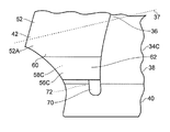
- FIG. 5 is an enlarged cross-sectional view in the direction of arrows C-C in FIG. 2 .
- FIG. 6 is a further enlarged view of a portion of the composite turbomachine blade shown in FIG. 2 .
- FIG. 7 is a further enlarged view of an alternative embodiment of a portion of the composite turbomachine blade shown in FIG. 2 .
- FIG. 8 is a further enlarged view of another embodiment of a portion of the composite turbomachine blade shown in FIG. 2 .
- a turbofan gas turbine engine 10 as shown in FIG. 1 , comprises in flow series an intake 11 , a fan 12 , an intermediate pressure compressor 13 , a high pressure compressor 14 , a combustor 15 , a high pressure turbine 16 , an intermediate pressure turbine 17 , a low pressure turbine 18 and an exhaust 19 .
- the high pressure turbine 16 is arranged to drive the high pressure compressor 14 via a first shaft 26 .
- the intermediate pressure turbine 17 is arranged to drive the intermediate pressure compressor 13 via a second shaft 28 and the low pressure turbine 19 is arranged to drive the fan 12 via a third shaft 30 .
- a first portion of the air flows through, and is compressed by, the intermediate pressure compressor 13 and the high pressure compressor 14 and is supplied to the combustor 15 .
- Fuel is injected into the combustor 15 and is burnt in the air to produce hot exhaust gases which flow through, and drive, the high pressure turbine 16 , the intermediate pressure turbine 17 and the low pressure turbine 18 .
- the hot exhaust gases leaving the low pressure turbine 18 flow through the exhaust 19 to provide propulsive thrust.
- a second portion of the air bypasses the main engine to provide propulsive thrust.
- the fan 12 comprises a fan rotor 32 carrying a plurality of circumferentially spaced radially outwardly extending fan blades 34 .
- the fan blades 34 are composite fan blades and each fan blade 34 comprises a composite material including reinforcing fibres in a matrix material.
- Each fan blade 34 comprises an aerofoil portion 36 , a shank portion 38 and a root portion 40 .
- the aerofoil portion 36 has a leading edge 42 , a trailing edge 44 , a pressure surface 46 extending from the leading edge 42 to the trailing edge 44 , a suction surface 48 extending from the leading edge 42 to the trailing edge 44 and a tip 50 remote from the root portion 40 .
- the composite fan blade 34 also has a metallic protective member 52 arranged in the region 54 of the leading edge 42 of the aerofoil portion 36 of the fan blade 34 .
- the metallic protective member 52 is adhesively bonded to the composite material in the region 54 of the leading edge 42 of the aerofoil portion 36 of the composite fan blade 34 .
- the metallic protective member 52 thus has portions 52 A and 52 B adhesively bonded to the pressure surface 46 and the suction surface 48 respectively of the aerofoil portion 36 of the composite fan blade 34 .
- the metallic protective member 52 extends the full length of the aerofoil portion 36 from the tip 50 to the shank portion 38 .
- the metallic protective member 52 also has two metallic projections 56 and 58 which extend from an end, a radially inner end, 60 of the metallic protective member 52 nearest the root portion 40 towards the root portion 40 of the composite fan blade 34 .
- the metallic projections 56 and 58 reduce the local peak stress levels in the composite material, the adhesive and the metallic protective member and increase high cycle fatigue strength of the composite material, the adhesive and the metallic protective member.
- the metallic projections 56 and 58 are adhesively bonded, as shown at 61 , to the pressure surface 46 and the suction surface 48 respectively of the aerofoil portion 36 of the composite fan blade 34 .
- the metallic protective member 52 only extends a relatively small distance onto the shank portion 38 of the fan blade 34 and does not extend onto the root portion 40 of the fan blade 34 , the metallic projections 56 and 58 extend onto the shank portion 38 and thus there is only a relatively small amount of metallic protective member 52 at the leading edge of the shank portion 38 .
- the metallic protective member 52 extends to a position radially below an annulus line 37 , the annulus line 37 defines a position radially outwardly of which a working fluid is arranged to flow over the aerofoil portion 36 of the fan blade 34 in operation and radially inwardly of which working fluid is not arranged to flow over the shank portion 38 and the root portion 40 in operation.
- the shank portion 38 and the root portion 40 do not have aerodynamic surfaces.
- a first one of the metallic projections 56 is arranged on the first surface 62 of the shank portion 38 of the composite fan blade 34 and a second one of the metallic projections 58 is arranged on a second surface 64 of the shank portion 38 of the composite fan blade 34 .
- the metallic projections 56 and 58 extend from the metallic protective member 52 onto the first surface 62 and second surface 64 of the shank portion 38 from the pressure surface 46 and suction surface 48 respectively of the aerofoil portion 36 of the composite fan blade 34 .
- the metallic projections 56 and 58 are flexible, resilient, because there is no interconnecting portion of metal extending around the leading edge of the shank portion 38 .
- the metallic projections 56 and 58 effectively extend the end 60 of the metallic protective member 52 and the change in stiffness between the root portion 40 of the composite fan blade 34 and the metallic protective member 52 is made much less severe. This has the effect of reducing local peak stresses during an impact by a bird and increasing the high cycle fatigue strength during steady operating conditions of the turbofan gas turbine engine 10 .
- the metallic projections 56 and 58 increase the area for adhesive bonding between the metallic protective member 52 and the composite fan blade 34 .
- the metallic projections 56 and 58 minimise stresses in the bond regions between the metallic protective member 52 and the composite fan blade 34 and spreads the stresses radially inwardly of the annulus line 37 .
- the metallic projections 56 and 58 taper in thickness, have chamfers, 57 and 59 towards the root portion 40 of the composite fan blade 34 .
- the metallic projections 56 and 58 may reduce in thickness towards the root portion 40 of the composite fan blade 34 , the metallic projections 56 and may reduce in thickness gradually or in a stepped manner.
- the portions 52 A and 52 B of the metallic protective member 52 taper in thickness, have chamfers, 53 A and 53 B in a direction towards the trailing edge 44 of the composite fan blade 34 .
- the chamfers 57 and 59 on the metallic projections 56 and 58 and the chamfers 53 A and 53 B on the portions 52 A and 52 B of the metallic protective member 52 also contribute to the effect of reducing local peak stresses during an impact by a bird and increasing the high cycle fatigue strength during steady operating conditions of the turbofan gas turbine engine 10 .
- FIGS. 2 , 3 and 7 An alternative arrangement of fan blade 34 B is shown in FIGS. 2 , 3 and 7 , and this is similar to that shown in FIGS. 2 , 3 and 6 and like parts are denoted by like numerals.
- the fan blade 34 B differs in that the metallic projections 56 B and 58 B extend onto, and are adhesively bonded to the root portion 40 of the composite fan blade 34 B.
- This arrangement provides an electrically conductive path for lightning from the metallic protective member 52 of the aerofoil portion 36 of the composite fan blade 34 B radially inwardly to the fan rotor 32 , the fan rotor 32 is metallic and thus conducts the lightning away from the composite fan blades 34 B in use.
- the electrically conductive path is provided by contact between the metallic projections 56 B and/or 58 B and the fan rotor 32 or by close proximity, a small gap, between the metallic projections 56 B and/or 58 B and the fan rotor 32 such that the lightning may cross the small gap during a lightning strike.
- FIGS. 2 , 3 and 8 A further arrangement of fan blade 34 C is shown in FIGS. 2 , 3 and 8 , and this is similar to that shown in FIGS. 2 , 3 and 6 and like parts are denoted by like numerals.
- the fan blade 34 C differs in that the metallic projections 56 C and 58 C have localised electrically conducting leads 70 and 72 which extend onto, and are adhesively bonded to the root portion 40 of the composite fan blade 34 C.
- This arrangement also provides an electrically conductive path for lightning from the metallic protective member 52 of the aerofoil portion 36 of the composite fan blade 34 C radially inwardly to the fan rotor 32 , the fan rotor 32 is metallic and thus conducts the lightning away from the composite fan blades 34 C.
- the electrically conducting leads 70 and 72 are electrically connected to the fan rotor 32 in use.
- the root portion 40 of the fan blade 34 may be a dovetail root, or a fir tree root, for location in a correspondingly shaped slot in the fan rotor 32 .
- the reinforcing fibres of the composite material may comprise carbon fibres and/or glass fibres and the matrix material of the composite material may comprise a thermosetting resin, e.g. an epoxy resin.
- the reinforcing fibres may comprise boron fibres, aramid fibres or polyaramid fibres, e.g. Kevler®, or any other suitable fibres.
- the matrix material may comprise thermoplastic materials, e.g. PEEK polyetheretherketone.
- the fan rotor may comprise a titanium alloy or any other suitable metal or alloy.
- the metallic protective member may comprise a titanium alloy, e.g. Ti-6-4 which consists of 6 wt % aluminium, 4 wt % vanadium and the remainder titanium plus minor additions and incidental impurities.
- the metallic protective member may comprise a nickel alloy, e.g. IN318, or steel or any other suitable metal or alloy.
- a protective member and associated projections comprising other materials may be used.
- present invention has been described with reference to a composite turbofan gas turbine engine fan blade the present invention is equally applicable to other composite gas turbine engine rotor blades, e.g. composite compressor blades.
- present invention is equally applicable to other composite turbomachine rotor blades and composite turbomachine stator vanes.
Abstract
Description
Claims (18)
Applications Claiming Priority (2)
| Application Number | Priority Date | Filing Date | Title |
|---|---|---|---|
| GBGB1011228.2A GB201011228D0 (en) | 2010-07-05 | 2010-07-05 | A composite turbomachine blade |
| GB1011228.2 | 2010-07-05 |
Publications (2)
| Publication Number | Publication Date |
|---|---|
| US20120003100A1 US20120003100A1 (en) | 2012-01-05 |
| US8851855B2 true US8851855B2 (en) | 2014-10-07 |
Family
ID=42669153
Family Applications (1)
| Application Number | Title | Priority Date | Filing Date |
|---|---|---|---|
| US13/160,028 Active 2033-06-01 US8851855B2 (en) | 2010-07-05 | 2011-06-14 | Composite turbomachine blade |
Country Status (4)
| Country | Link |
|---|---|
| US (1) | US8851855B2 (en) |
| EP (1) | EP2405101B1 (en) |
| CN (1) | CN102312682B (en) |
| GB (1) | GB201011228D0 (en) |
Cited By (11)
| Publication number | Priority date | Publication date | Assignee | Title |
|---|---|---|---|---|
| US20130156588A1 (en) * | 2011-12-14 | 2013-06-20 | James R. Murdock | Electrical grounding for fan blades |
| US20140083080A1 (en) * | 2012-09-27 | 2014-03-27 | United Technologies Corporation | Diode Electrical Ground for Fan Blades |
| US20150104324A1 (en) * | 2012-01-30 | 2015-04-16 | Ihi Corporation | Fan rotor blade of aircraft jet engine |
| US20150300176A1 (en) * | 2014-02-07 | 2015-10-22 | United Technologies Corporation | Spinner for Electrically Grounding Fan Blades |
| US20180105241A1 (en) * | 2016-10-17 | 2018-04-19 | General Electric Company | Apparatus for dovetail chord relief for marine propeller |
| US20180274375A1 (en) * | 2015-09-28 | 2018-09-27 | Safran Aircraft Engines | Blade comprising a folded leading edge shield and method of manufacturing the blade |
| US10421557B2 (en) * | 2013-09-18 | 2019-09-24 | Ihi Corporation | Electric conduction structure for jet engine |
| US10483659B1 (en) | 2018-11-19 | 2019-11-19 | United Technologies Corporation | Grounding clip for bonded vanes |
| US10703452B2 (en) | 2016-10-17 | 2020-07-07 | General Electric Company | Apparatus and system for propeller blade aft retention |
| US11053861B2 (en) | 2016-03-03 | 2021-07-06 | General Electric Company | Overspeed protection system and method |
| US20230003133A1 (en) * | 2019-12-18 | 2023-01-05 | Safran Aircraft Engines | Blade made of composite material with variable-density attached leading edge |
Families Citing this family (34)
| Publication number | Priority date | Publication date | Assignee | Title |
|---|---|---|---|---|
| CA2879954A1 (en) * | 2012-07-30 | 2014-02-06 | General Electric Company | Metal leading edge protective strips, corresponding airfoil and method of producing |
| US9212559B2 (en) | 2012-09-07 | 2015-12-15 | United Technologies Corporation | Electrical grounding for blades |
| US8876482B2 (en) | 2012-09-11 | 2014-11-04 | United Technologies Corporation | Electrical grounding for blade sheath |
| US9297272B2 (en) | 2012-10-24 | 2016-03-29 | United Technologies Corporation | Grounding for fan blades on an underblade spacer |
| US20140174098A1 (en) * | 2012-12-20 | 2014-06-26 | United Technologies Corporation | Turbine disc with reduced neck stress concentration |
| US9617860B2 (en) * | 2012-12-20 | 2017-04-11 | United Technologies Corporation | Fan blades for gas turbine engines with reduced stress concentration at leading edge |
| EP2964893B1 (en) | 2013-03-08 | 2020-10-21 | United Technologies Corporation | Fan blades with protective sheaths and galvanic shields |
| WO2014143256A1 (en) * | 2013-03-14 | 2014-09-18 | United Technologies Corporation | Frangible sheath for a fan blade of a gas turbine engine |
| US9945237B2 (en) | 2013-03-15 | 2018-04-17 | United Technologies Corporation | Lock for retaining minidisks with rotors of a gas turbine engine |
| WO2014143262A1 (en) * | 2013-03-15 | 2014-09-18 | United Technologies Corporation | Locally extended leading edge sheath for fan airfoil |
| GB201306479D0 (en) * | 2013-04-10 | 2013-05-22 | Rolls Royce Plc | A method of through-thickness reinforcing a laminated material |
| JP2016527426A (en) | 2013-05-29 | 2016-09-08 | ゼネラル・エレクトリック・カンパニイ | Composite airfoil metal patch |
| JP6150054B2 (en) * | 2013-07-02 | 2017-06-21 | 株式会社Ihi | Stator blade structure and turbofan jet engine using the same |
| US20160230774A1 (en) * | 2013-09-27 | 2016-08-11 | United Technologies Corporation | Fan blade assembly |
| WO2015108616A1 (en) | 2014-01-16 | 2015-07-23 | General Electric Company | Composite blade root stress reducing shim |
| US9745851B2 (en) * | 2015-01-15 | 2017-08-29 | General Electric Company | Metal leading edge on composite blade airfoil and shank |
| US10012238B2 (en) * | 2015-04-24 | 2018-07-03 | United Technologies Corporation | Electrostatic discharge prevention for a fan blade |
| US11149642B2 (en) | 2015-12-30 | 2021-10-19 | General Electric Company | System and method of reducing post-shutdown engine temperatures |
| US10677259B2 (en) | 2016-05-06 | 2020-06-09 | General Electric Company | Apparatus and system for composite fan blade with fused metal lead edge |
| US10337405B2 (en) | 2016-05-17 | 2019-07-02 | General Electric Company | Method and system for bowed rotor start mitigation using rotor cooling |
| US10583933B2 (en) | 2016-10-03 | 2020-03-10 | General Electric Company | Method and apparatus for undercowl flow diversion cooling |
| US10947993B2 (en) | 2017-11-27 | 2021-03-16 | General Electric Company | Thermal gradient attenuation structure to mitigate rotor bow in turbine engine |
| US10760428B2 (en) | 2018-10-16 | 2020-09-01 | General Electric Company | Frangible gas turbine engine airfoil |
| US11434781B2 (en) | 2018-10-16 | 2022-09-06 | General Electric Company | Frangible gas turbine engine airfoil including an internal cavity |
| US10837286B2 (en) | 2018-10-16 | 2020-11-17 | General Electric Company | Frangible gas turbine engine airfoil with chord reduction |
| US10746045B2 (en) | 2018-10-16 | 2020-08-18 | General Electric Company | Frangible gas turbine engine airfoil including a retaining member |
| US11111815B2 (en) | 2018-10-16 | 2021-09-07 | General Electric Company | Frangible gas turbine engine airfoil with fusion cavities |
| US11149558B2 (en) | 2018-10-16 | 2021-10-19 | General Electric Company | Frangible gas turbine engine airfoil with layup change |
| FR3087699B1 (en) * | 2018-10-30 | 2021-11-26 | Safran Aircraft Engines | HYBRIDIZATION OF THE FIBERS OF THE FIBER REINFORCEMENT OF A DAWN |
| TWI790328B (en) | 2018-12-07 | 2023-01-21 | 宏碁股份有限公司 | Fan |
| FR3095368B1 (en) * | 2019-04-26 | 2021-04-23 | Safran Aircraft Engines | PROCESS FOR REPAIRING A BLADE IN COMPOSITE MATERIAL |
| US11674399B2 (en) | 2021-07-07 | 2023-06-13 | General Electric Company | Airfoil arrangement for a gas turbine engine utilizing a shape memory alloy |
| US11668317B2 (en) | 2021-07-09 | 2023-06-06 | General Electric Company | Airfoil arrangement for a gas turbine engine utilizing a shape memory alloy |
| US11879411B2 (en) | 2022-04-07 | 2024-01-23 | General Electric Company | System and method for mitigating bowed rotor in a gas turbine engine |
Citations (20)
| Publication number | Priority date | Publication date | Assignee | Title |
|---|---|---|---|---|
| US1793775A (en) * | 1929-06-04 | 1931-02-24 | Hartzell Industries | Metal tipping for propellers |
| US2389760A (en) * | 1940-08-24 | 1945-11-27 | Rotol Ltd | Airscrew |
| US3200477A (en) | 1962-11-21 | 1965-08-17 | Enstrom Corp | Helicopter tail rotor structure and method of construction |
| GB1186486A (en) | 1968-10-22 | 1970-04-02 | Rolls Royce | Fibre Reinforced Blade |
| US3892612A (en) * | 1971-07-02 | 1975-07-01 | Gen Electric | Method for fabricating foreign object damage protection for rotar blades |
| GB1500776A (en) | 1976-04-08 | 1978-02-08 | Rolls Royce | Fibre reinforced composite structures |
| US4738594A (en) * | 1986-02-05 | 1988-04-19 | Ishikawajima-Harima Jukogyo Kabushiki Kaisha | Blades for axial fans |
| US4784575A (en) * | 1986-11-19 | 1988-11-15 | General Electric Company | Counterrotating aircraft propulsor blades |
| US5141400A (en) * | 1991-01-25 | 1992-08-25 | General Electric Company | Wide chord fan blade |
| US5449273A (en) * | 1994-03-21 | 1995-09-12 | United Technologies Corporation | Composite airfoil leading edge protection |
| GB2288441A (en) | 1994-04-05 | 1995-10-18 | Mtu Muenchen Gmbh | Composite blade with leading edge protection |
| US5800129A (en) * | 1995-11-29 | 1998-09-01 | Eurocopter France S.A. Aeroport International Marseille-Provence | Blade with shielding for enhanced protection against lightning, for rotorcraft rotor |
| US6250880B1 (en) * | 1997-09-05 | 2001-06-26 | Ventrassist Pty. Ltd | Rotary pump with exclusively hydrodynamically suspended impeller |
| US6413051B1 (en) | 2000-10-30 | 2002-07-02 | General Electric Company | Article including a composite laminated end portion with a discrete end barrier and method for making and repairing |
| EP1302562A1 (en) | 2001-10-12 | 2003-04-16 | General Electric Company | Method for removing metal cladding from airfoil substrate |
| US20080038113A1 (en) * | 2005-04-27 | 2008-02-14 | Honda Motor Co., Ltd. | Flow-guiding member unit and its production method |
| US20080075601A1 (en) * | 2006-09-26 | 2008-03-27 | Snecma | Composite turbomachine blade with metal reinforcement |
| US20090148302A1 (en) * | 2007-12-10 | 2009-06-11 | Leahy Kevin P | Main rotor blade with integral tip section |
| US7637721B2 (en) * | 2005-07-29 | 2009-12-29 | General Electric Company | Methods and apparatus for producing wind energy with reduced wind turbine noise |
| EP2159378A2 (en) | 2008-08-28 | 2010-03-03 | Rolls-Royce plc | Rotor blade |
Family Cites Families (2)
| Publication number | Priority date | Publication date | Assignee | Title |
|---|---|---|---|---|
| CN100353030C (en) * | 2003-04-19 | 2007-12-05 | 通用电气公司 | Mutti-assembly mixing turbine blade |
| FR2921099B1 (en) * | 2007-09-13 | 2013-12-06 | Snecma | DAMPING DEVICE FOR DRAWINGS OF COMPOSITE MATERIAL |
-
2010
- 2010-07-05 GB GBGB1011228.2A patent/GB201011228D0/en not_active Ceased
-
2011
- 2011-06-14 EP EP11169739.7A patent/EP2405101B1/en active Active
- 2011-06-14 US US13/160,028 patent/US8851855B2/en active Active
- 2011-07-05 CN CN201110186147.0A patent/CN102312682B/en active Active
Patent Citations (20)
| Publication number | Priority date | Publication date | Assignee | Title |
|---|---|---|---|---|
| US1793775A (en) * | 1929-06-04 | 1931-02-24 | Hartzell Industries | Metal tipping for propellers |
| US2389760A (en) * | 1940-08-24 | 1945-11-27 | Rotol Ltd | Airscrew |
| US3200477A (en) | 1962-11-21 | 1965-08-17 | Enstrom Corp | Helicopter tail rotor structure and method of construction |
| GB1186486A (en) | 1968-10-22 | 1970-04-02 | Rolls Royce | Fibre Reinforced Blade |
| US3892612A (en) * | 1971-07-02 | 1975-07-01 | Gen Electric | Method for fabricating foreign object damage protection for rotar blades |
| GB1500776A (en) | 1976-04-08 | 1978-02-08 | Rolls Royce | Fibre reinforced composite structures |
| US4738594A (en) * | 1986-02-05 | 1988-04-19 | Ishikawajima-Harima Jukogyo Kabushiki Kaisha | Blades for axial fans |
| US4784575A (en) * | 1986-11-19 | 1988-11-15 | General Electric Company | Counterrotating aircraft propulsor blades |
| US5141400A (en) * | 1991-01-25 | 1992-08-25 | General Electric Company | Wide chord fan blade |
| US5449273A (en) * | 1994-03-21 | 1995-09-12 | United Technologies Corporation | Composite airfoil leading edge protection |
| GB2288441A (en) | 1994-04-05 | 1995-10-18 | Mtu Muenchen Gmbh | Composite blade with leading edge protection |
| US5800129A (en) * | 1995-11-29 | 1998-09-01 | Eurocopter France S.A. Aeroport International Marseille-Provence | Blade with shielding for enhanced protection against lightning, for rotorcraft rotor |
| US6250880B1 (en) * | 1997-09-05 | 2001-06-26 | Ventrassist Pty. Ltd | Rotary pump with exclusively hydrodynamically suspended impeller |
| US6413051B1 (en) | 2000-10-30 | 2002-07-02 | General Electric Company | Article including a composite laminated end portion with a discrete end barrier and method for making and repairing |
| EP1302562A1 (en) | 2001-10-12 | 2003-04-16 | General Electric Company | Method for removing metal cladding from airfoil substrate |
| US20080038113A1 (en) * | 2005-04-27 | 2008-02-14 | Honda Motor Co., Ltd. | Flow-guiding member unit and its production method |
| US7637721B2 (en) * | 2005-07-29 | 2009-12-29 | General Electric Company | Methods and apparatus for producing wind energy with reduced wind turbine noise |
| US20080075601A1 (en) * | 2006-09-26 | 2008-03-27 | Snecma | Composite turbomachine blade with metal reinforcement |
| US20090148302A1 (en) * | 2007-12-10 | 2009-06-11 | Leahy Kevin P | Main rotor blade with integral tip section |
| EP2159378A2 (en) | 2008-08-28 | 2010-03-03 | Rolls-Royce plc | Rotor blade |
Non-Patent Citations (2)
| Title |
|---|
| European Search Report dated May 15, 2014 from European Patent Application No. 11 16 9739. |
| Search Report issued in British Application No. GB1011228.2 dated Oct. 13, 2010. |
Cited By (17)
| Publication number | Priority date | Publication date | Assignee | Title |
|---|---|---|---|---|
| US9376924B2 (en) * | 2011-12-14 | 2016-06-28 | United Technologies Corporation | Electrical grounding for fan blades |
| US20130156588A1 (en) * | 2011-12-14 | 2013-06-20 | James R. Murdock | Electrical grounding for fan blades |
| US10066490B2 (en) * | 2012-01-30 | 2018-09-04 | Ihi Corporation | Fan rotor blade of aircraft jet engine |
| US20150104324A1 (en) * | 2012-01-30 | 2015-04-16 | Ihi Corporation | Fan rotor blade of aircraft jet engine |
| US9394805B2 (en) * | 2012-09-27 | 2016-07-19 | United Technologies Corporation | Diode electrical ground for fan blades |
| US20140083080A1 (en) * | 2012-09-27 | 2014-03-27 | United Technologies Corporation | Diode Electrical Ground for Fan Blades |
| US10421557B2 (en) * | 2013-09-18 | 2019-09-24 | Ihi Corporation | Electric conduction structure for jet engine |
| US20150300176A1 (en) * | 2014-02-07 | 2015-10-22 | United Technologies Corporation | Spinner for Electrically Grounding Fan Blades |
| US9896936B2 (en) * | 2014-02-07 | 2018-02-20 | United Technologies Corporation | Spinner for electrically grounding fan blades |
| US20180274375A1 (en) * | 2015-09-28 | 2018-09-27 | Safran Aircraft Engines | Blade comprising a folded leading edge shield and method of manufacturing the blade |
| US10883374B2 (en) * | 2015-09-28 | 2021-01-05 | Safran Aircraft Engines | Blade comprising a folded leading edge shield and method of manufacturing the blade |
| US11053861B2 (en) | 2016-03-03 | 2021-07-06 | General Electric Company | Overspeed protection system and method |
| US20180105241A1 (en) * | 2016-10-17 | 2018-04-19 | General Electric Company | Apparatus for dovetail chord relief for marine propeller |
| US10703452B2 (en) | 2016-10-17 | 2020-07-07 | General Electric Company | Apparatus and system for propeller blade aft retention |
| US11052982B2 (en) * | 2016-10-17 | 2021-07-06 | General Electric Company | Apparatus for dovetail chord relief for marine propeller |
| US10483659B1 (en) | 2018-11-19 | 2019-11-19 | United Technologies Corporation | Grounding clip for bonded vanes |
| US20230003133A1 (en) * | 2019-12-18 | 2023-01-05 | Safran Aircraft Engines | Blade made of composite material with variable-density attached leading edge |
Also Published As
| Publication number | Publication date |
|---|---|
| CN102312682B (en) | 2015-07-29 |
| GB201011228D0 (en) | 2010-08-18 |
| CN102312682A (en) | 2012-01-11 |
| EP2405101A2 (en) | 2012-01-11 |
| US20120003100A1 (en) | 2012-01-05 |
| EP2405101A3 (en) | 2014-07-23 |
| EP2405101B1 (en) | 2015-08-12 |
Similar Documents
| Publication | Publication Date | Title |
|---|---|---|
| US8851855B2 (en) | Composite turbomachine blade | |
| EP2348192B1 (en) | Fan airfoil sheath | |
| US9657577B2 (en) | Rotor blade with bonded cover | |
| US7736130B2 (en) | Airfoil and method for protecting airfoil leading edge | |
| JP3924333B2 (en) | Composite blade | |
| US10539027B2 (en) | Gas turbine engine | |
| US8206118B2 (en) | Airfoil attachment | |
| EP2378079A2 (en) | Composite leading edge sheath and dovetail root undercut | |
| US20050118028A1 (en) | Detachable leading edge for airfoils | |
| US20140086751A1 (en) | Annulus filler for axial flow machine | |
| CN111287802A (en) | Multi-material leading edge protector | |
| US10934851B2 (en) | Leading edge shield | |
| US20160230774A1 (en) | Fan blade assembly | |
| EP3049632B1 (en) | Fan blade assembly | |
| US20140219808A1 (en) | Sheath with extended wings | |
| US20200157953A1 (en) | Composite fan blade with abrasive tip |
Legal Events
| Date | Code | Title | Description |
|---|---|---|---|
| AS | Assignment |
Owner name: ROLLS-ROYCE PLC, GREAT BRITAIN Free format text: ASSIGNMENT OF ASSIGNORS INTEREST;ASSIGNORS:JAMES, DARREN IVOR;MERRIMAN, NICHOLAS MICHAEL;REEL/FRAME:026445/0001 Effective date: 20110524 |
|
| STCF | Information on status: patent grant |
Free format text: PATENTED CASE |
|
| AS | Assignment |
Owner name: COMPOSITE TECHNOLOGY AND APPLICATIONS LIMITED, GRE Free format text: ASSIGNMENT OF ASSIGNORS INTEREST;ASSIGNOR:ROLLS-ROYCE PLC.;REEL/FRAME:035154/0566 Effective date: 20140410 |
|
| MAFP | Maintenance fee payment |
Free format text: PAYMENT OF MAINTENANCE FEE, 4TH YEAR, LARGE ENTITY (ORIGINAL EVENT CODE: M1551) Year of fee payment: 4 |
|
| AS | Assignment |
Owner name: ROLLS-ROYCE PLC, UNITED KINGDOM Free format text: ASSIGNMENT OF ASSIGNORS INTEREST;ASSIGNOR:COMPOSITE TECHNOLOGY AND APPLICATIONS LIMITED;REEL/FRAME:048379/0896 Effective date: 20171231 |
|
| MAFP | Maintenance fee payment |
Free format text: PAYMENT OF MAINTENANCE FEE, 8TH YEAR, LARGE ENTITY (ORIGINAL EVENT CODE: M1552); ENTITY STATUS OF PATENT OWNER: LARGE ENTITY Year of fee payment: 8 |