US8321062B2 - Systems and method for operating a wind turbine having active flow control - Google Patents
Systems and method for operating a wind turbine having active flow control Download PDFInfo
- Publication number
- US8321062B2 US8321062B2 US12/613,274 US61327409A US8321062B2 US 8321062 B2 US8321062 B2 US 8321062B2 US 61327409 A US61327409 A US 61327409A US 8321062 B2 US8321062 B2 US 8321062B2
- Authority
- US
- United States
- Prior art keywords
- wind turbine
- control system
- blade
- air distribution
- flow control
- Prior art date
- Legal status (The legal status is an assumption and is not a legal conclusion. Google has not performed a legal analysis and makes no representation as to the accuracy of the status listed.)
- Expired - Fee Related
Links
- 238000000034 method Methods 0.000 title claims abstract description 88
- 230000009471 action Effects 0.000 claims abstract description 39
- 238000009826 distribution Methods 0.000 claims description 108
- 238000004140 cleaning Methods 0.000 claims description 95
- 238000001514 detection method Methods 0.000 claims description 49
- 239000012530 fluid Substances 0.000 claims description 44
- 238000004891 communication Methods 0.000 claims description 41
- 238000005259 measurement Methods 0.000 claims description 31
- 230000004044 response Effects 0.000 claims description 25
- 238000002955 isolation Methods 0.000 claims description 16
- 230000007613 environmental effect Effects 0.000 claims description 11
- 238000005452 bending Methods 0.000 claims description 6
- 238000005192 partition Methods 0.000 claims description 5
- 230000005465 channeling Effects 0.000 claims description 4
- 230000003213 activating effect Effects 0.000 claims 2
- 239000003570 air Substances 0.000 description 76
- 238000012360 testing method Methods 0.000 description 16
- 230000006870 function Effects 0.000 description 15
- 239000012080 ambient air Substances 0.000 description 14
- 239000003365 glass fiber Substances 0.000 description 9
- 238000012544 monitoring process Methods 0.000 description 9
- 239000012459 cleaning agent Substances 0.000 description 7
- 241000238631 Hexapoda Species 0.000 description 6
- 230000000712 assembly Effects 0.000 description 6
- 238000000429 assembly Methods 0.000 description 6
- 238000001228 spectrum Methods 0.000 description 6
- 238000012546 transfer Methods 0.000 description 6
- 230000003247 decreasing effect Effects 0.000 description 5
- 239000010410 layer Substances 0.000 description 5
- 238000001556 precipitation Methods 0.000 description 5
- 238000007664 blowing Methods 0.000 description 4
- 230000000694 effects Effects 0.000 description 4
- 238000012423 maintenance Methods 0.000 description 4
- 230000001680 brushing effect Effects 0.000 description 3
- 239000003599 detergent Substances 0.000 description 3
- 238000004080 punching Methods 0.000 description 3
- 230000002829 reductive effect Effects 0.000 description 3
- 238000002791 soaking Methods 0.000 description 3
- 238000005507 spraying Methods 0.000 description 3
- XLYOFNOQVPJJNP-UHFFFAOYSA-N water Substances O XLYOFNOQVPJJNP-UHFFFAOYSA-N 0.000 description 3
- 230000001133 acceleration Effects 0.000 description 2
- 230000005540 biological transmission Effects 0.000 description 2
- 239000004020 conductor Substances 0.000 description 2
- 238000011217 control strategy Methods 0.000 description 2
- 230000001934 delay Effects 0.000 description 2
- 230000003111 delayed effect Effects 0.000 description 2
- 238000007599 discharging Methods 0.000 description 2
- 239000007788 liquid Substances 0.000 description 2
- 239000000463 material Substances 0.000 description 2
- 238000012806 monitoring device Methods 0.000 description 2
- 230000003287 optical effect Effects 0.000 description 2
- 230000036961 partial effect Effects 0.000 description 2
- 239000002245 particle Substances 0.000 description 2
- 238000003860 storage Methods 0.000 description 2
- 239000002344 surface layer Substances 0.000 description 2
- 230000036962 time dependent Effects 0.000 description 2
- 230000001052 transient effect Effects 0.000 description 2
- 230000001960 triggered effect Effects 0.000 description 2
- LFQSCWFLJHTTHZ-UHFFFAOYSA-N Ethanol Chemical compound CCO LFQSCWFLJHTTHZ-UHFFFAOYSA-N 0.000 description 1
- 229910000831 Steel Inorganic materials 0.000 description 1
- 238000009825 accumulation Methods 0.000 description 1
- 230000002411 adverse Effects 0.000 description 1
- 230000008859 change Effects 0.000 description 1
- 238000006243 chemical reaction Methods 0.000 description 1
- 239000003795 chemical substances by application Substances 0.000 description 1
- 239000011248 coating agent Substances 0.000 description 1
- 230000008878 coupling Effects 0.000 description 1
- 238000010168 coupling process Methods 0.000 description 1
- 238000005859 coupling reaction Methods 0.000 description 1
- 125000004122 cyclic group Chemical group 0.000 description 1
- 238000013461 design Methods 0.000 description 1
- 230000003292 diminished effect Effects 0.000 description 1
- 239000000428 dust Substances 0.000 description 1
- 238000005516 engineering process Methods 0.000 description 1
- 239000000835 fiber Substances 0.000 description 1
- 238000001914 filtration Methods 0.000 description 1
- 230000007935 neutral effect Effects 0.000 description 1
- -1 particulates Substances 0.000 description 1
- 230000002093 peripheral effect Effects 0.000 description 1
- 230000003449 preventive effect Effects 0.000 description 1
- 230000008569 process Effects 0.000 description 1
- 230000002441 reversible effect Effects 0.000 description 1
- 230000001932 seasonal effect Effects 0.000 description 1
- 239000007787 solid Substances 0.000 description 1
- 230000003068 static effect Effects 0.000 description 1
- 239000010959 steel Substances 0.000 description 1
- 239000000126 substance Substances 0.000 description 1
- 238000013519 translation Methods 0.000 description 1
- 239000013598 vector Substances 0.000 description 1
Images


Classifications
-
- F—MECHANICAL ENGINEERING; LIGHTING; HEATING; WEAPONS; BLASTING
- F03—MACHINES OR ENGINES FOR LIQUIDS; WIND, SPRING, OR WEIGHT MOTORS; PRODUCING MECHANICAL POWER OR A REACTIVE PROPULSIVE THRUST, NOT OTHERWISE PROVIDED FOR
- F03D—WIND MOTORS
- F03D7/00—Controlling wind motors
- F03D7/02—Controlling wind motors the wind motors having rotation axis substantially parallel to the air flow entering the rotor
- F03D7/022—Adjusting aerodynamic properties of the blades
-
- F—MECHANICAL ENGINEERING; LIGHTING; HEATING; WEAPONS; BLASTING
- F03—MACHINES OR ENGINES FOR LIQUIDS; WIND, SPRING, OR WEIGHT MOTORS; PRODUCING MECHANICAL POWER OR A REACTIVE PROPULSIVE THRUST, NOT OTHERWISE PROVIDED FOR
- F03D—WIND MOTORS
- F03D17/00—Monitoring or testing of wind motors, e.g. diagnostics
-
- F—MECHANICAL ENGINEERING; LIGHTING; HEATING; WEAPONS; BLASTING
- F05—INDEXING SCHEMES RELATING TO ENGINES OR PUMPS IN VARIOUS SUBCLASSES OF CLASSES F01-F04
- F05B—INDEXING SCHEME RELATING TO WIND, SPRING, WEIGHT, INERTIA OR LIKE MOTORS, TO MACHINES OR ENGINES FOR LIQUIDS COVERED BY SUBCLASSES F03B, F03D AND F03G
- F05B2260/00—Function
- F05B2260/83—Testing, e.g. methods, components or tools therefor
-
- Y—GENERAL TAGGING OF NEW TECHNOLOGICAL DEVELOPMENTS; GENERAL TAGGING OF CROSS-SECTIONAL TECHNOLOGIES SPANNING OVER SEVERAL SECTIONS OF THE IPC; TECHNICAL SUBJECTS COVERED BY FORMER USPC CROSS-REFERENCE ART COLLECTIONS [XRACs] AND DIGESTS
- Y02—TECHNOLOGIES OR APPLICATIONS FOR MITIGATION OR ADAPTATION AGAINST CLIMATE CHANGE
- Y02E—REDUCTION OF GREENHOUSE GAS [GHG] EMISSIONS, RELATED TO ENERGY GENERATION, TRANSMISSION OR DISTRIBUTION
- Y02E10/00—Energy generation through renewable energy sources
- Y02E10/70—Wind energy
- Y02E10/72—Wind turbines with rotation axis in wind direction
Definitions
- the embodiments described herein relate generally to methods and systems for operating a wind turbine having an active flow control system and, more particularly, to methods and systems for removing debris from the active flow control system and/or preventing an accumulation of debris within the active flow control system.
- AFC Active Flow Control
- airfoil refers to a turbine blade, a wing, and/or any other suitable airfoil.
- AFC systems enable flow control to be selectively applied to an airfoil.
- At least some known AFC systems use air distribution systems to manipulate a boundary layer of air flowing across a surface of an airfoil.
- Known AFC systems include actuators that can be divided in two categories, depending on their net-mass-flow.
- the first category is zero-net-mass-flow actuators, such as synthetic jet actuators
- the second category is nonzero-net-mass-flow actuators, such as air ejection actuators, which may be steady or unsteady and/or blowing and/or suction actuators.
- AFC systems are subjected to fluid flows that can contain debris, fouling of AFC perforations and/or apertures by debris is one of the obstacles for wide scale application of AFC on wind turbine blades, aircraft wings, and other airfoils.
- debris refers to dirt, dust, insects, insect remains, particles, particulates, substances, suspended liquids and/or solids, and/or any other material that may contact and accumulate in and/or on the wind turbine blades and/or other airfoils.
- perforation and “aperture” can be used interchangeably throughout this application.
- fouling of the AFC apertures by debris has an adverse effect on AFC system performance.
- components, other than the perforations, of at least some known AFC systems are susceptible to fouling as well.
- ambient air possibly polluted with debris, is drawn into the AFC system to feed the actuators.
- polluted intake air may foul the air distribution system, the actuators, and/or the perforations of the AFC system.
- Such fouling of the perforations and/or other components of known AFC systems may alter fluid flows across an airfoil such that the fluid flows deviate from clean-state fluid flows for which the blade is designed to yield. Additionally, fouling on blade surfaces and/or within AFC systems may reduce a power output of a system using airfoils and/or an AFC system, such as a wind turbine.
- manually cleaning each aperture of an AFC system is not practical because of a number of apertures in at least some known AFC systems and/or a duration of time that is required for the wind turbine to be offline for such manual cleaning.
- a method and/or system for maintaining a wind turbine by cleaning an AFC system and/or preventing fouling of an AFC system. Further, such a method and/or system preferably minimizes or eliminates the need to manually clean the AFC system and/or blade. Moreover, it is desirable for such method and/or system to automatically perform an action based on operational data acquired from the wind turbine and, more particularly, on an operational characteristic of the AFC system.
- a method of operating a wind turbine that includes a flow control system includes operating the wind turbine in a first mode, operating the wind turbine in a second mode that is different than the first mode, acquiring operational data of the wind turbine during at least the second mode, determining an effectiveness of the flow control system using the acquired operational data, and performing an action based on the effectiveness of the flow control system.
- a flow control system for use with a wind turbine.
- the flow control system includes an air distribution system at least partially defined within at least one blade of the wind turbine.
- the air distribution system includes at least one aperture defined through an outer surface of the blade.
- the flow control system further includes a control system in operational control communication with the air distribution system.
- the control system is configured to operate the wind turbine in a first mode, operate the wind turbine in a second mode that is different than the first mode, acquire operational data of the wind turbine during at least the second mode, determine an effectiveness of the flow control system using the acquired operational data, and perform an action based on the effectiveness of the flow control system.
- a wind turbine in yet another aspect, includes at least one blade and a flow control system having an air distribution system at least partially defined within the blade.
- the air distribution system includes at least one aperture defined through an outer surface of the blade.
- the wind turbine further includes a control system in operational control communication with the flow control system.
- the control system is configured to operate the wind turbine in a first mode, operate the wind turbine in a second mode that is different than the first mode, acquire operational data of the wind turbine during at least the second mode, determine an effectiveness of the flow control system using the acquired operational data, and perform an action based on the effectiveness of the flow control system.
- the systems and methods described herein are configured to automatically perform an action based on acquired data relating to an AFC system.
- the embodiments described herein can selectively monitor operations of a wind turbine and/or alter an operation of wind turbine to acquire data relevant to determining an effectiveness of the AFC system.
- FIGS. 1-12 show exemplary embodiments of the systems and methods described herein.
- FIG. 1 is a perspective view of an exemplary wind turbine.
- FIG. 2 is a schematic view of an exemplary flow control system that may be used with the wind turbine shown in FIG. 1 .
- FIG. 3 is a schematic view of an exemplary detection system that may be used with the flow control system shown in FIG. 2 .
- FIG. 4 is a schematic view of an alternative exemplary detection system that may be used with the flow control system shown in FIG. 2 .
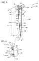
- FIG. 5 is a schematic view of a second alternative exemplary detection system that may be used with the flow control system shown in FIG. 2 .
- FIG. 6 is an enlarged cross-sectional view of a portion of the detection system shown in FIG. 5 .
- FIG. 7 is a schematic view of an exemplary alternative flow control system that may be used with the wind turbine shown in FIG. 1 .
- FIG. 8 is an enlarged cross-sectional view of a portion of the flow control system shown in FIG. 7 .
- FIG. 9 is a flowchart of an exemplary method of operating a wind turbine that may be used with the flow control systems shown in FIGS. 2 and 7 .
- FIG. 10 is a flowchart of an exemplary method of operating a wind turbine that may be used with a flow control system having the detection system shown in FIG. 3 .
- FIG. 11 is a flowchart of an exemplary method of operating a wind turbine that may be used with a flow control system having the detection system shown in FIG. 4 .
- FIG. 12 is a flowchart of an exemplary method of operating a wind turbine that may be used with a flow control system having the detection system shown in FIGS. 5 and 6 .
- the embodiments described herein provide a monitoring and control system for active flow control (AFC) system fouling.
- a control system described herein detects a state of fouling, detects opportunities for correcting and/or preventing fouling, and applies an active cleaning strategy to correct and/or prevent fouling.
- the embodiments described herein include acquiring measurements of loads in turbine structures to enable monitoring of AFC effectiveness for each blade.
- the embodiments described herein monitor a power curve to determine AFC system effectiveness; vary a level of AFC response over a period to measure performance of the AFC system; acquire measurements of loads in each blade to enable monitoring of AFC effectiveness for each blade; in parallel to determining the effectiveness of the AFC system, acquire measurements of AFC system internal quantities; acquire measurements of an amount of light that is allowed through apertures of the AFC system; and/or perform and/or switch to any suitable cleaning mode or combination of cleaning modes.
- the embodiments described herein facilitate monitoring the AFC system for fouling and/or performance. For example, by comparing how individual blades perform over one rotation, such as one rotation in a changing wind field, a state of fouling of at least one blade is determined.
- a light intensity can be transmitted as a 0-20 milliamp (mA) signal, a voltage level, a power level, and/or an artificial translation to a dimensionless scale.
- mA milliamp
- FIG. 1 is a perspective view of an exemplary wind turbine 10 .
- wind turbine 10 is a nearly horizontal-axis wind turbine.
- wind turbine 10 may have any suitable tilt angle.
- wind turbine 10 may be a vertical axis wind turbine.
- wind turbine 10 includes a tower 12 that extends from a supporting surface 14 , a nacelle 16 mounted on tower 12 , and a rotor 18 that is coupled to nacelle 16 .
- Rotor 18 includes a rotatable hub 20 and at least one blade 22 coupled to and extending outward from hub 20 .
- rotor 18 has three blades 22 .
- rotor 18 includes more or less than three blades 22 .
- tower 12 is fabricated from tubular steel such that a cavity (not shown in FIG. 1 ) is defined between supporting surface 14 and nacelle 16 .
- tower 12 is any suitable type of tower. A height of tower 12 is selected based upon factors and conditions known in the art.
- Blades 22 are spaced about hub 20 to facilitate rotating rotor 18 to enable kinetic energy to be transferred from the wind into usable mechanical energy, and subsequently, electrical energy. Blades 22 are mated to hub 20 by coupling a blade root portion 24 to hub 20 at a plurality of load transfer regions 26 . Load transfer regions 26 have a hub load transfer region and a blade load transfer region (both not shown in FIG. 1 ). Loads induced to blades 22 are transferred to hub 20 via load transfer regions 26 .
- blades 22 have a length of between approximately 30 meters (m) (99 feet (ft)) and approximately 120 (394 ft).
- blades 22 may have any length that enables wind turbine 10 to function as described herein.
- rotor 18 As wind strikes blades 22 from a direction 28 , rotor 18 is rotated about an axis of rotation 30 .
- blades 22 As blades 22 are rotated and subjected to centrifugal forces, blades 22 are also subjected to various forces and moments. As such, blades 22 may deflect and/or rotate from a neutral, or non-deflected, position to a deflected position.
- a pitch angle of blades 22 may be changed by a pitch adjustment system 32 to control power, load, and/or noise generated by wind turbine 10 by adjusting an angular position a profile of at least one blade 22 relative to wind vectors.
- Pitch axes 34 for blades 22 are illustrated.
- a pitch of each blade 22 is controlled individually by a control system 36 .
- the blade pitch for all blades may be controlled simultaneously by control system 36 .
- a yaw direction of nacelle 16 may be controlled about a yaw axis 38 to position blades 22 with respect to direction 28 .
- control system 36 is shown as being centralized with in nacelle 16 , however control system 36 may be a distributed system throughout wind turbine 10 , on supporting surface 14 , within a wind farm, and/or at a remote control center.
- Control system 36 includes a processor 40 configured to perform the methods and/or steps described herein. Further, many of the other components described herein include a processor.
- processor is not limited to integrated circuits referred to in the art as a computer, but broadly refers to a controller, a microcontroller, a microcomputer, a programmable logic controller (PLC), an application specific integrated circuit, and other programmable circuits, and these terms are used interchangeably herein. It should be understood that a processor and/or control system can also include memory, input channels, and/or output channels.
- memory may include, without limitation, a computer-readable medium, such as a random access memory (RAM), and a computer-readable non-volatile medium, such as flash memory.
- RAM random access memory
- flash memory Alternatively, a floppy disk, a compact disc-read only memory (CD-ROM), a magneto-optical disk (MOD), and/or a digital versatile disc (DVD) may also be used.
- input channels may include, without limitation, sensors and/or computer peripherals associated with an operator interface, such as a mouse and a keyboard.
- output channels may include, without limitation, a control device, an operator interface monitor and/or a display.
- Processors described herein process information transmitted from a plurality of electrical and electronic devices that may include, without limitation, sensors, actuators, compressors, control systems, and/or monitoring devices. Such processors may be physically located in, for example, a control system, a sensor, a monitoring device, a desktop computer, a laptop computer, a PLC cabinet, and/or a distributed control system (DCS) cabinet.
- RAM and storage devices store and transfer information and instructions to be executed by the processor(s). RAM and storage devices can also be used to store and provide temporary variables, static (i.e., non-changing) information and instructions, or other intermediate information to the processors during execution of instructions by the processor(s). Instructions that are executed may include, without limitation, flow control system control commands. The execution of sequences of instructions is not limited to any specific combination of hardware circuitry and software instructions.
- wind turbine 10 includes at least one environmental sensor 42 .
- Environmental sensor 42 includes at least one of a wind direction sensor, a wind speed sensor, a temperature sensor, a rain/snow/hail/precipitation sensor, a humidity sensor, an ice sensor, and/or any other suitable sensor configured to detect and/or measure ambient and/or environment conditions.
- Sensor 42 is coupled in communication with control system 36 for transmitting data to control system 36 .
- FIG. 2 is a schematic view of an exemplary flow control system 100 that may be used with wind turbine 10 .
- FIG. 3 is a schematic view of an exemplary detection system 300 that may be used with flow control system 100 .
- FIG. 4 is a schematic view of an alternative exemplary detection system 400 that may be used with flow control system 100 .
- FIG. 5 is a schematic view of a second alternative exemplary detection system 500 that may be used with flow control system 100 .
- FIG. 6 is an enlarged cross-sectional view of a portion of detection system 500 .
- Components shown in FIG. 1 are labeled with similar reference number in FIGS. 2-6 . Additional or alternative components are indicated by dashed lines.
- flow control system 100 is a nonzero-net-mass flow control system that includes an air distribution system 102 .
- Control system 36 considered to be a component of flow control system 100 and is in operational control communication with air distribution system 102 .
- operational control communication refers to a link, such as a conductor, a wire, and/or a data link, between two or more components of wind turbine 10 that enables signals, electric currents, and/or commands to be communicated between the two or more components.
- the link is configured to enable one component to control an operation of another component of wind turbine 10 using the communicated signals, electric currents, and/or commands.
- Air distribution system 102 includes at least one flow control device 104 , at least one manifold 106 , and at least one aperture 108 . At least one flow control device 104 , a respective manifold 106 , and one or more corresponding apertures 108 form an assembly 110 . Each blade 22 includes an assembly 110 at least partially defined therein. As such, air distribution system 102 includes a plurality of flow control devices 104 , a plurality of manifolds 106 , and a plurality of apertures 108 . Alternatively, at least one blade 22 includes an assembly 110 . In the exemplary embodiment, each assembly 110 is substantially similar, however, at least one assembly 110 may be different than at least one other assembly 110 . Further, although in the exemplary embodiment each assembly 110 includes a flow control device 104 , at least two assemblies 110 may share a common flow control device 104 .
- Flow control device 104 is, for example, a pump, a compressor, a fan, a blower, and/or any other suitable device for controlling a flow of a fluid.
- flow control device 104 and/or assembly 110 includes a valve (not shown) that is configured to regulate a flow within air distribution system 102 , such as a flow rate and/or a flow direction.
- flow control device 104 is reversible for changing a direction of a fluid flow 112 .
- air distribution system 102 includes one flow control device 104 for each blade 22 of wind turbine 10 , however, it should be understood that air distribution system 102 can include any suitable number of flow control devices 104 .
- Control system 36 is in operational control communication with each flow control device 104 for controlling fluid flows through air distribution system 102 .
- Control system 36 may be directly coupled in operational control communication with each flow control device 104 and/or may be coupled in operational control communication with each flow control device 104 via a communication hub and/or any other suitable communication device(s).
- Each flow control device 104 is in flow communication with at least one manifold 106 .
- flow control device 104 is in flow communication with each manifold 106 of air distribution system 102 .
- a flow control device 104 is coupled within a respective blade 22 at a root end 114 of each manifold 106 and/or a root portion 24 of each blade 22 .
- flow control device 104 may be in any suitable position within wind turbine 10 and/or on supporting surface 14 (shown in FIG. 1 ) with respect to at least one manifold 106 .
- each manifold 106 is at least partially defined along an interior surface 116 within respective blade 22 and extends generally along a respective pitch axis 34 (shown in FIG. 1 ) from root end 114 of manifold 106 to a tip end 118 of manifold 106 .
- tip end 118 is not necessarily positioned within a tip 44 of blade 22 , but rather, is positioned nearer to tip 44 than manifold root end 114 .
- apertures 108 are defined at a predetermined portion 120 of a length of blade 22 from root end 114 within tip end 118 .
- manifold 106 may have any suitable configuration, cross-sectional shape, length, and/or dimensions that enables air distribution system 102 and/or flow control system 100 to function as described herein. It should also be understood that one or more components of blade 22 can be used to form manifold 106 .
- air distribution system 102 also includes at least one aperture 108 in flow communication with respective manifold 106 . More specifically, in the exemplary embodiment, air distribution system 102 includes a plurality of apertures 108 defined along a suction side 122 of respective blade 22 . Although apertures 108 are shown as being aligned in a line along suction side 122 , it should be understood that apertures 108 may be positioned anywhere along suction side 122 of blade 22 that enables flow control system 100 to function as described herein. Alternatively or additionally, apertures 108 are defined through a pressure side 124 of blade 22 . In the exemplary embodiment, aperture 108 is defined though an outer surface 126 of blade 22 for providing flow communication between manifold 106 and ambient air 128 .
- Flow control devices 104 are, in the exemplary embodiment, in flow communication with ambient air 128 via an opening 130 defined between hub 20 and a hub cover 132 .
- wind turbine 10 does not include hub cover 132 , and ambient air 128 is drawn into air distribution system 102 through an opening 130 near hub 20 .
- flow control devices 104 are configured to draw in ambient air 128 though opening 130 and to discharge fluid flow 112 generated from ambient air 128 into respective manifold 106 .
- opening 130 may be defined at any suitable location within hub 20 , nacelle 16 , blade 22 , tower 12 , and/or auxiliary device (not shown) that enables air distribution system 102 to function as described herein.
- air distribution system 102 may include more than one opening 130 for drawing air into air distribution system 102 , such as including one opening 130 for each flow control device 104 .
- a filter is included within opening 130 for filtering air 128 entering air distribution system 102 . It should be understood that the filter referred to herein can filter particles from a fluid flow and/or separate liquid from the fluid flow.
- flow control system 100 includes detection system 300 .
- Detection system 300 includes an isolation device 302 .
- Isolation device 302 includes four bellows 304 , 306 , 308 , and 310 .
- isolation device 302 includes only two bellows 304 and 306 .
- bellows 304 , 306 , 308 , and 310 are coupled to an outer surface 312 of a conduit 314 and are configured to expand and retract.
- bellows 304 , 306 , 308 , and/or 310 when bellows 304 , 306 , 308 , and/or 310 are expanded, bellows 304 , 306 , 308 , and/or 310 contact interior surface 116 of manifold 106 to facilitate preventing fluid flow 112 through a portion 316 of manifold 106 adjacent isolation device 302 . Further, when bellows 304 , 306 , 308 , and/or 310 are expanded, isolation device 302 partitions manifold 106 into two or more chambers, such as chambers 318 , 320 , and/or 322 , shown in FIG. 3 and described in more detail below.
- Conduit 314 is configured to be inserted into manifold 106 when bellows 304 , 306 , 308 , and 310 are retracted. Between bellows 306 and 308 , at least a portion of outer surface 312 of conduit 314 is configured to be air-permeable. Conduit 314 and a portion 324 of manifold 106 between bellows 306 and bellows 308 define a testing chamber 318 when bellows 306 and 308 are expanded. In the exemplary embodiment, conduit 314 between bellows 304 and 306 and bellows 308 and 310 is also air-permeable and defines a first reference chamber 320 and a second reference chamber 322 .
- First reference chamber 320 is defined when bellows 304 and 306 are expanded, and second reference chamber 322 is defined when bellows 308 and 310 are expanded.
- isolation device 302 does not include second reference chamber 322 .
- Detection system 300 also includes, in the exemplary embodiment, a first reference pressure sensor 326 , a test pressure sensor 328 , and a second reference pressure sensor 330 .
- First reference pressure sensor 326 is positioned within first reference chamber 320
- test pressure sensor 328 is positioned within testing chamber 318
- second reference pressure sensor 330 is positioned within second reference chamber 322 .
- Sensors 326 , 328 , and 330 are coupled in communication with control system 36 for transmitting pressure data to control system 36 , as described in more detail with respect to FIG. 10 .
- a pressure (P reference ) within testing chamber 318 is a predetermined percentage and/or any suitable amount below at least a pressure (P ref1 ) within first reference chamber 320 .
- the predetermined percentage and/or other suitable amount defines a threshold (X pressure ), which is determined empirically and/or by any suitable method.
- the threshold (P threshold ) is any suitable pressure that enables detection system 300 to function as described herein. In one embodiment, the threshold (P threshold ) is equal to about 0.1*P ref1 .
- a volumetric flow rate (Q clean ) when apertures 108 within portion 324 are substantially free of debris, a volumetric flow rate (Q clean ) generates a pressure (P reference ) within testing chamber 318 that is higher than at least the pressure (P ref1 ) within first reference chamber 320 .
- a volumetric flow rate (Q fouled ) is channeled through a substantially fouled air distribution system 102 and/or flow control system 100 , which generates a pressure (P fouled ) within testing chamber 318 .
- a relationship between a pressure difference ( ⁇ P 2 ) and a volumetric flow rate in a fouled state is given by the equation: ⁇ P 2 ⁇ P fouled ( Q fouled ) ⁇ P ref1 (Eq.
- the fouling state of air distribution system 102 and/or flow control system 100 is determined by comparing the pressure difference ( ⁇ P 1 ) in the clean state to the pressure difference ( ⁇ P 2 ) in the fouled state using the following equation: ⁇ P 2 ⁇ P 1 > ⁇ P threshold , (Eq. 5) where the threshold ( ⁇ P threshold ) is any suitable pressure that enables detection system 300 to function as described herein.
- the comparison between the pressure difference ( ⁇ P 1 ) and the pressure difference ( ⁇ P 2 ) can be performed using any suitable mathematic operation(s).
- a pressure P ref2 within second reference chamber 322 can be used to perform calculations similar to the calculations performed using pressure P ref1 and/or can be used in combination with pressure P ref1 to perform the calculations described herein.
- detection device 300 can also be used to selectively clean apertures 108 and/or manifold 106 by isolating testing chamber 318 from a remaining portion 332 of manifold 106 .
- a cleaning agent is channeled through manifold 106 for cleaning apertures 108
- the cleaning agent is channeled into conduit 314 by expanded bellows 304 .
- the cleaning agent is then discharged from testing chamber 318 into manifold 106 and through apertures 108 within portion 324 .
- air is channeled through detection device 300 to particular apertures 108 for cleaning thereof.
- detection device 300 selectively channels the cleaning agent to portion 324 of manifold 106 and associated apertures 108 .
- detection device 300 applies a concentrated cleaning action to apertures 108 .
- the cleaning action applied by detection device 300 includes, but is not limited to including, soaking, brushing, vacuuming, blowing, jetting, punching, and/or spraying.
- detection device 300 is a Rovver® robotic crawler manufactured by General Electric Company that is configured to detect fouling and/or perform cleaning as described herein (Rovver is a registered trademark of Envirosight, LLC of Randolph, N.J.).
- detection device 300 is sized such that first reference chamber 320 and/or second reference chamber 322 prevents fluid flow 112 and/or the cleaning agent from being discharged from apertures 108 other than apertures 108 within portion 324 .
- a length L 1 of detection device 300 is selected such that first reference chamber 320 and second reference chamber 322 are each adjacent to at least one aperture 108 .
- flow control system 100 includes detection system 400 .
- Detection system 400 includes at least one external light sensor 402 and at least one internal light sensor 404 . Although one external light sensor 402 and two internal light sensors 404 are shown in FIG. 4 and described herein, it should be understood that detection system 400 can include any suitable number of external light sensors 402 and/or internal light sensors 404 .
- at least one sensor positioned within flow control system 100 and/or air distribution system 102 is configured to measure external light using lenses, tubes, and/or any other suitable components that enable detection system 400 to function as described herein.
- external light sensor 402 and internal light sensors 404 are coupled in communication with control system 36 for transmitting data to control system 36 , as described in more detail below.
- External light sensor 402 is positioned on outer surface 126 of blade 22 adjacent to portion 120 of blade 22 having apertures 108 defined therethrough. External light sensor 402 is configured to detect and/or measure an amount of ambient light (L amb ). Internal light sensor 404 is positioned within manifold 106 to detect and/or measure an amount of light (L manifold ) entering manifold 106 through at least one aperture 108 . When apertures 108 and/or manifold 106 is substantially free of debris, a ratio of light (L manifold ) to light (L amb ) is greater than, or equal to, a predetermined threshold (X Light1 ), which is determined empirically and/or by any suitable method. Such a relationship is represented by the following equation:
- flow control system 100 includes detection system 500 .
- Detection system 500 includes a glass fiber 502 and a light source 504 configured to emit light 506 through glass fiber 502 .
- detection system 500 includes any suitable light source and/or light conductor that enables detection system 500 to function as described herein.
- glass fiber 502 is formed from any suitable material that enables detection system 500 to function as described herein, such as fiber optic cable.
- Glass fiber 502 is embedded in a skin 510 of blade 22 at least partially adjacent to manifold 106 . More specifically, in the exemplary embodiment, glass fiber 502 includes a first cable 514 and a second cable 516 within skin 510 .
- first cable 514 is coupled to light source 504
- second cable 516 is coupled in light transmitting communication with a light receiver 512
- Light receiver 512 is positioned within root portion 24 of blade 22 and is in light transmitting communication with control system 36 .
- Light source 504 is configured to emit light 506 through first cable 514 and light receiver is configured to receive light from second cable 516 .
- control system 36 is in operational control communication with light source 504 for selectively emitting light 506 through glass fiber 502 .
- light source 504 and light receiver 512 are described as being positioned in root portion 24 of blade 22 , it should be understood that light source 504 and/or light receiver 512 may be in any suitable position within wind turbine 10 .
- Detection system 500 further includes at least one transmitter 518 and at least one receiver 520 .
- transmitter 518 and receiver 520 are each lenses.
- Transmitter 518 is coupled in communication with first cable 514 of glass fiber 502 for emission of light 506 from transmitter 518 .
- Receiver 520 is positioned to receive emitted light (L emitted ) and communicate a measurement of light received (L received ) to light receiver 512 via second cable 516 .
- receiver 520 is configured to reflect light (L reflected ) to transmitter 518
- transmitter 518 is configured to receive reflected light (L reflected ) and communicate a measurement of emitted light (L emitted ) and a measurement of reflected light (L reflected ) to control system 36 .
- a ratio of emitted light (L emitted ) to received light (L received ) is less than, or equal to, a threshold (X Light2 ), which is determined empirically and/or by any suitable method.
- X Light2 a threshold
- At least one transmitter 518 and receiver 520 pair is positioned proximate at least one aperture 108 as shown in FIG. 6 . More specifically, transmitter 518 is coupled through a wall 134 defining aperture 108 , and receiver 520 is coupled to wall 134 opposite transmitter 518 . Alternatively, a plurality of transmitter 518 and receiver 520 pairs are positioned proximate a plurality of respective apertures 108 are coupled in series or parallel such that detection system 500 includes a plurality of transmitters 518 and a plurality of receivers 520 . Additionally or alternatively, transmitter 518 and receiver 520 are positioned within manifold 106 , opening 103 (shown in FIG.
- transmitter 518 and/or receiver 520 can be embedded is a strip that is inserted into the mould of blade 22 such that transmitter 518 and/or receiver 520 are pre-fabricated into blade 22 . As such, alignment of transmitter 518 and receiver 520 is simplified.
- detection system 300 , 400 , and/or 500 can be used singly or in combination to perform the methods described herein. Further, detection systems 300 , 400 , and/or 500 can be permanently installed within flow control system 100 and/or temporarily installed within flow control system 100 .
- flow control system 100 is used to provide AFC for wind turbine 10 . More specifically, control system 36 controls air distribution system 102 to draw in ambient air 128 and discharge fluid flow 112 through at least one aperture 108 . Operation of one assembly 110 will be described herein, however, it should be understood that in one embodiment each assembly 110 functions similarly. Further, assemblies 110 can be controlled to operate in substantial synchronicity and/or each assembly 110 may be controlled separately such that a fluid flow about each blade 22 may be manipulated independently. When assemblies 110 are controlled in synchronicity, flow control system 100 can be controlled by control system 36 to maintain a predetermined load spectrum, power level, and/or noise level.
- control system 36 controls flow control device 104 to draw in ambient air 128 to generate fluid flow 112 having one or more predetermined parameters, such as a velocity, a mass flow rate, a pressure, a temperature, and/or any suitable flow parameter.
- Flow control device 104 channels fluid flow 112 through manifold 106 from root end 114 to tip end 118 .
- any suitable control methods and/or components, such as pitching blade(s) 22 can alternatively or additionally be used to control a load spectrum, a power level, and/or a noise level of wind turbine 10 .
- fluid flow 112 is discharged from air distribution system 102 and flow control system 100 through apertures 108 .
- Discharged fluid flow 112 facilitates manipulating at least a boundary layer of a fluid flow across outer surface 126 of blade 22 . More specifically, discharging fluid flow 112 at suction side 122 of blade 22 increases the lift on blade 22 , which increases the power generated by wind turbine 10 .
- flow control device 104 may be operated to draw in ambient air 128 through apertures 108 into manifold 106 for discharge from nacelle 16 , hub 20 , and/or any other suitable location. As such, ambient air 128 is drawn in from the boundary layer to manipulate the boundary layer.
- FIG. 7 is a schematic view of an exemplary alternative flow control system 200 that may be used with wind turbine 10 .
- FIG. 8 is an enlarged cross-sectional view of a portion of flow control system 200 . Components shown in FIG. 1 are labeled with similar reference numbers in FIGS. 7 and 8 .
- flow control system 200 is a zero-net-mass flow control system that includes an air distribution system 202 .
- Control system 36 may be considered as a component of flow control system 200 and is in operational control communication with air distribution system 202 .
- Air distribution system 202 includes at least one actuator 204 , at least one communication link 206 , and at least one aperture 208 .
- Actuator 204 , communication link 206 , and apertures 208 define an assembly 210 .
- each blade 22 includes a respective assembly 210 .
- air distribution system 202 includes a plurality of actuators 204 , communication links 206 , and apertures 208 .
- air distribution system 202 includes one common communication link 206 for assemblies 210 .
- at least one blade 22 includes an assembly 210 having communication link 206 .
- communication link 206 provides operational control communication between control system 36 and at least one actuator 204 .
- communication link 206 provides operational control communication between control system 36 and a plurality of actuators 204 within an assembly 210 .
- Communications links 206 may be directly coupled in communication with control system 36 and/or in communication with control system 36 via a communications hub and/or any other suitable communication device.
- actuator 204 , communication link 206 , and/or aperture 208 are at least partially defined in blade 22 .
- Actuator 204 is, in the exemplary embodiment, any known or contemplated actuator configured to form a synthetic jet 212 of fluid.
- synthetic jet refers to a jet of fluid that is created by cyclic movement of a diaphragm and/or piston 217 , where the jet flow is synthesized from the ambient fluid.
- Synthetic jet 212 may be considered a fluid flow through flow control system 200 .
- actuator 204 includes a housing 216 and a diaphragm and/or a piston 217 within housing 216 . Diaphragm and/or piston 217 can be mechanically, piezoelectrically, pneumatically, magnetically, and/or otherwise controlled to form synthetic jet 212 .
- actuator 204 is coupled to an interior surface 218 of blade 22 and is aligned with aperture 208 such that synthetic jet 212 and/or ambient air 214 flows through aperture 208 .
- Aperture 208 is defined within blade 22 , and, more specifically, through an outer surface 220 of blade 22 . Further, in the exemplary embodiment, at least one assembly 210 of air distribution system 202 includes a plurality of actuators 204 and a plurality of apertures 208 . As such, air distribution system 202 includes an array 222 of apertures 208 defined through blade 22 . In the exemplary embodiment, apertures 208 are defined along a suction side 224 of each blade 22 .
- apertures 208 and/or actuators 204 are shown as being aligned in a line along suction sides 224 , it should be understood that apertures 208 and/or actuators 204 may be positioned anywhere along suction side 224 of blade 22 that enables flow control system 200 to function as described herein. Additionally or alternatively, apertures 208 are defined through a pressure side 226 of blade 22 , and/or actuators 204 are coupled to interior surface 218 of any suitable side of blade 22 . In the exemplary embodiment, aperture 208 is configured to provide flow communication between a respective actuator housing 216 and ambient air 214 .
- flow control system 200 may include other suitable components to cleaning and/or maintaining components of wind turbine 10 depending on a configuration of wind turbine 10 .
- flow control system 200 can include a fluid distribution system configured to channel a fluid into air distribution system 202 .
- flow control system 200 is used to provide AFC for wind turbine 10 . More specifically, control system 36 controls air distribution system 202 to draw in ambient air 214 and generate synthetic jet 212 through at least one aperture 208 . Operation of one assembly 210 will be described herein, however, it should be understood that each assembly 210 functions similarly. Further, assemblies 210 can be controlled to operate in substantial synchronicity and/or each assembly 210 may be controlled separately such that a fluid flow about each blade 22 may be manipulated separately. When assemblies 210 are controlled in synchronicity, flow control system 200 can be controlled by control system 36 to maintain a predetermined load spectrum, power level, and/or noise level.
- control system 36 instructs actuator 204 to alternately draw ambient air 214 into housing 216 (also referred to herein as a “breath-in stroke”) and discharge synthetic jet 212 (also referred to herein as a “breath-out stroke”) from housing 216 using diaphragm and/or piston 217 to generate synthetic jet 212 having one or more predetermined parameters, such as a velocity, a mass flow rate, a pressure, a temperature, and/or any suitable flow parameter.
- Synthetic jets 212 facilitate manipulating at least a boundary layer of a fluid flow across outer surface 220 of blade 22 .
- discharging synthetic jets 212 at suction side 224 of blade 22 increases the lift on blade 22 , which increases the power generated by wind turbine 10 .
- any suitable control methods and/or components, such as pitching blade(s) 22 can alternatively or additionally be used to control a load spectrum, a power level, and/or a noise level of wind turbine 10 .
- FIG. 9 is a flowchart of a method 600 of operating wind turbine 10 (shown in FIG. 1 ).
- Method 600 By performing method 600 , fouling of blade 22 (shown in FIG. 1 ) and/or flow control system 100 (shown in FIG. 2 ) and/or flow control system 200 (shown in FIG. 7 ) is facilitated to be corrected and/or prevented.
- Method 600 is performed at least partially by control system 36 (shown in FIG. 1 ) sending or transmitting commands and/or instructions to components of wind turbine 10 , such as air distribution system 102 and/or 202 (shown in FIGS. 2 and 7 ), detection systems 300 , 400 , and/or 500 (shown in FIGS. 3-6 ), and/or any other suitable component.
- Processor 40 (shown in FIG.
- control system 36 within control system 36 is programmed with code segments configured to perform method 600 .
- method 600 is encoded on a computer-readable medium that is readable by control system 36 .
- control system 36 and/or processor 40 is configured to read computer-readable medium for performing method 600 .
- method 600 is performed periodically according to a predetermined corrective schedule, a predetermined preventative schedule, condition-triggered automated operation, and/or condition-triggered manual operation.
- control system 36 performs method 600 after control system 36 and/or a human operator determines optimal conditions exist, such as a low power-generating time period, a low wind speed time period, a high wind speed time period, and/or any optimal time period, for performing method 600 .
- control system 36 is configured to determine when fouling has occurred and/or will occur and perform method 600 upon making such a determination.
- method 600 is also performed to correct and/or prevent an icing condition on blade 22 by using a de-icing agent, such as an alcohol, within flow control system 100 and/or 202 . Further, method 600 is performed to prevent fouling of blade 22 and/or flow control system 100 and/or 200 by using a non-binding coating agent, such as a wax, to form a non-binding surface layer on blade 22 and/or within flow control system 100 and/or 200 .
- Method 600 used for de-icing and/or for forming a non-binding surface layer can be performed by control system 36 according to a predetermined seasonal schedule and/or selectively by an operator of control system 36 .
- method 600 includes operating 602 wind turbine 10 in a first or normal mode.
- normal mode refers to a mode of operating wind turbine 10 , flow control system 100 , and/or air distribution system 102 such that flow control system 100 and/or air distribution system 102 drives a flow 112 of fluid to increase lift on blade 22 .
- the normal mode includes normal operation over a substantially entire power curve; operating when a wind speed is too low to generate power but wind turbine 10 is prepared to generate power; using constant and variable speed-ranges; operating within a peak shaver range; operating in an above rated condition; and/or performing a storm cut out.
- Flow characteristics of fluid flow 112 during the normal mode are determined empirically and/or are predetermined to achieve optimal lift on blade 22 depending on ambient conditions, such as a wind speed and/or a wind direction, precipitation, and/or other atmospheric and/or environmental conditions. At least one flow characteristic of fluid flow 112 may be adjusted and/or varied during the normal mode, based on changing ambient conditions and/or operating characteristics of wind turbine 10 , to facilitate achieving optimal blade lift.
- Flow control system 100 and/or air distribution system 102 is operated 602 in the normal mode according to a certain schedule and/or based on wind turbine data.
- control system 36 operates 602 flow control system 100 and/or air distribution system 102 in the normal mode by: acquiring current and/or historical data measured on wind turbine 10 , such as wind speed, temperature, a rotor component position, a rotor component speed, a rotor component acceleration, forces at several points of wind turbine 10 , and/or moments at several points of wind turbine 10 ; applying algorithms, such as models and/or maps, to the acquired data; and computing a best possible actuation, such as a state of flow control device 104 .
- operation 602 of flow control system 100 is substantially terminated because increased lift on blade 22 is not desired in such wind conditions.
- active flow control is terminated, enough fluid is discharged from aperture 108 to facilitate preventing insects from flying into air distribution system 102 .
- Such termination of active flow control is considered an off mode.
- wind turbine 10 is operated 604 in a second mode that is different than the normal mode.
- the term “second mode” refers to a mode of operating wind turbine 10 , flow control system 100 , and/or air distribution system 102 to achieve an outcome in addition to or different than optimal lift on blade 22 .
- control system 36 controls flow control system 100 and/or air distribution system 102 to facilitate altering the AFC response of flow control system 100 and/or air distribution system 102 .
- the second mode is a cleaning mode and/or a preventative mode. It should be understood that wind turbine 10 can be operated in more than two modes. For example, wind turbine 10 can further be operated in an ordinary operation mode, a full flow capacity mode, a non-zero flow mode, and/or a cleaning mode.
- a level of AFC response of flow control system 100 is varied over a period of time.
- the level of AFC response is varied among an off level, a partial flow rate level, and/or a full flow rate level over the time period.
- Control system 36 may vary the AFC response of flow control system 100 depending on ambient and/or environmental conditions, such as rain, fog, and/or insect load, and/or on operational parameters, such as at low wind speed and/or at above rated wind speed, which is an above rated wind speed with flow control system 100 in the off mode. Such conditions are determined and/or measured using environmental sensor 42 included within or on wind turbine 10 .
- control system 36 can modify pitch settings according to an AFC response level desired for detection and/or cleaning.
- flow control system 100 when wind turbine 10 is operating at below rated power, flow control system 100 usually operates 602 in the normal mode. However, during the second mode, a pitch angle of at least one blade 22 is altered to determine a pitch angle at which a stall occurs. Flow control system 100 usually delays the occurrence of a stall. As such, when the occurrence of a stall is not delayed substantially as designed or as in a clean condition, it may be determined that flow control system 100 is not functioning effectively. In another example, during the second mode, flow control system 100 can be operated 604 in the off mode to analyze power output and/or other parameters of wind turbine 10 with respect to the AFC response of flow control system 100 .
- Control system 36 acquires 606 operational data of wind turbine 10 during at least the second mode and determines 608 an effectiveness of flow control system 100 using the acquired operational data.
- the operational data used to perform the determination 608 includes design data, current operational data and/or historical operational data.
- control system 36 acquires 606 power output data to generate a power curve.
- the effectiveness of flow control system 100 can be determined 608 .
- effects of ambient conditions can be substantially eliminated by repeatedly acquiring power curve measurements to eliminate short term variation in ambient conditions.
- control system 36 acquires 606 measurements of loads in each blade 22 , a shaft, and/or other suitable components, i.e. a load spectrum, to enable monitoring of an AFC effectiveness for each blade 22 , the shaft, and/or other components because flow control system 100 affects blade lift and drag.
- blade sectional load measurements across a span of each blade 22 can be acquired 606 to determine 608 a local AFC effectiveness
- blade root bending moments for each blade 22 can be acquired 606 to determine 608 the AFC effectiveness for each blade 22 .
- one or more blades 22 can be tuned and/or maintained independently to achieve optimal lift during the normal mode.
- internal quantities of flow control system 100 can be acquired 606 with respect to time.
- the internal quantities include a power required in flow control device 104 to discharge fluid flow 112 from air distribution system 102 , as a function of ambient and operational variables; pressure and flow rate of flow control device 104 ; and/or pressure and flow rate in at least one manifold 106 of air distribution system 102 .
- Data regarding the internal quantities can be used to detect and/or monitor patterns over a time period. From the time-dependent patterns, the effectiveness of flow control system 100 is determined 608 . For example, if the power needed to generate a given fluid flow 112 increases, control system 608 determines that the effectiveness of flow control system 100 has decreased.
- control system 36 determines 608 that the effectiveness of flow control system 100 has decreased.
- the determined 608 effectiveness can be used for monitoring wind turbine 10 , transmitting a warning, transmitting an alarm, controlling wind turbine 10 and/or flow control system 100 , and/or any other suitable purpose.
- control system 36 acquires 606 a noise measurement and/or acquires 606 a measurement of a light, such as a point, line, and/or other suitable configuration, emitted from tower 12 by using a camera.
- Control system 363 may also be configured to emit light from apertures 108 defined through blade 22 and photograph the emitted light to determine 608 the effectiveness of flow control system 100 .
- control system 36 can also acquire 606 operational data during the normal mode for comparison with the operational data acquired 606 during the second mode. At any time after the operational data has been acquired 606 , wind turbine 10 can return to operating 612 in the first mode.
- control system 36 Based on the effectiveness of flow control system 100 , control system 36 performs 610 an action.
- the action is at least one of continuing to acquire 606 operational data, transmitting a warning signal to an operator of wind turbine 10 , transmitting an alarm signal to the operator of wind turbine 10 , changing a mode of operation of wind turbine 10 , and/or shutting down wind turbine 10 .
- a series of actions increasing in severity level are performed over time. When such a series of actions are performed there is a time interval between each action in the series.
- any transmission to the operator is a “smart message” that includes a determination by control system 36 as to what may be causing any detected transient in wind turbine operation.
- control system 36 performs 610 a plurality of actions, such as transmitting the warning signal to an operator without changing a mode of operation of wind turbine 10 and continuing to acquire 606 operational data, when the effectiveness of flow control system 100 does not increase, performing a cleaning mode to facilitate removing debris from flow control system 100 , when the effectiveness of flow control system 100 still does not increase, transmitting an alarm signal to the operator requesting that the operator take an action.
- control system 36 detects a state of fouling, detects an opportunity to correct the fouling, such as during a period of precipitation and/or a period of low wind speed detected using sensor 42 , and operates wind turbine 10 in a cleaning mode to facilitate removing debris from flow control system 100 .
- a cleaning mode includes channeling a cleaning fluid into air distribution system 102 and/or varying an operation of flow control device 104 to dislodge debris.
- the cleaning mode can include modifying operational parameters, such as pitch settings and/or rotor speed, to facilitate cleaning flow control system 100 .
- the cleaning mode includes using a cleaning device that is internal to air distribution system 102 as described above with respect to FIG. 3 and/or using a cleaning device that is external to air distribution system 102 .
- an external cleaning device (not shown) is used during the cleaning mode, the external cleaning device travels along length L of blade 22 on outer surface 126 .
- Any suitable components such as suction cups, rails, harnesses, cords, and/or wires, may be used to couple the external cleaning device to blade 22 .
- any suitable position indicators such as striping, a grid, bar codes, and/or magnets, may be positioned on outer surface 126 of blade 22 and/or within air distribution system 102 to facilitate properly positioning a cleaning device.
- the external cleaning device is configured to apply localized cleaning to apertures 108 that were determined to be fouled. More specifically, the external cleaning device is positioned on outer surface 126 adjacent apertures 108 to be cleaned.
- the cleaning device includes a positioning device, such as a global positioning system (GPS) device, to sense its location on wind turbine 10 and/or a recognition system, such as an optical recognition system, to properly localize its cleaning action.
- GPS global positioning system
- the external cleaning device uses any suitable cleaning agent, such as air, water, and/or detergent, and/or any suitable cleaning technique, such as soaking, brushing, vacuuming, blowing, jetting, punching, and/or spraying, to perform maintenance on flow control system 100 and/or air distribution system 102 .
- method 600 includes operating 602 wind turbine 10 in a first or normal mode.
- normal mode refers to a mode of operating wind turbine 10 , flow control system 200 , and/or air distribution system 202 such that flow control system 200 and/or air distribution system 202 generates synthetic jet 212 to modify lift on blade 22 .
- the normal mode includes normal operation over a substantially entire power curve; operating when a wind speed is too low to generate power but wind turbine 10 is prepared to generate power; using constant and variable speed-ranges; operating within a peak shaver range; operating in an above rated condition; and/or performing a storm cut out.
- Flow characteristics of synthetic jet 212 during the normal mode are determined empirically and/or are predetermined to achieve optimal lift on blade 22 depending on ambient conditions, such as a wind speed and/or a wind direction, precipitation, and/or other atmospheric and/or environmental conditions. At least one flow characteristic of synthetic jet 212 may be adjusted and/or varied during the normal mode, based on changing ambient conditions and/or operating characteristics of wind turbine 10 , to facilitate achieving optimal blade lift.
- Flow control system 200 and/or air distribution system 202 is operated 602 in the normal mode according to a certain schedule and/or based on wind turbine data.
- control system 36 operates 602 flow control system 200 and/or air distribution system 202 in the normal mode by: acquiring current and/or historical data measured on wind turbine 10 , such as wind speed, temperature, a rotor component position, a rotor component speed, a rotor component acceleration, forces at several points of wind turbine 10 , and/or moments at several points of wind turbine 10 ; applying algorithms, such as models and/or maps, to the acquired data; and computing a best possible actuation, such as a state of flow control device 104 and/or pitch adjustment system 32 .
- operation 602 of flow control system 200 is substantially terminated because increased lift on blade 22 is not desired in such wind conditions.
- active flow control is terminated, enough fluid is discharged from aperture 208 to facilitate preventing insects from flying into air distribution system 202 .
- Such termination of active flow control is considered an off mode.
- wind turbine 10 is operated 604 in a second mode that is different than the normal mode.
- the term “second mode” refers to a mode of operating wind turbine 10 , flow control system 200 , and/or air distribution system 202 to achieve an outcome in addition to or different than optimal lift on blade 22 .
- control system 36 controls flow control system 200 and/or air distribution system 202 to facilitate altering the AFC response of flow control system 200 and/or air distribution system 202 .
- the second mode is a cleaning mode and/or a preventative mode. It should be understood that wind turbine 10 can be operated in more than two modes. For example, wind turbine 10 can further be operated in an ordinary operation mode, a full flow capacity mode, a zero flow mode, and/or a cleaning mode.
- a level of AFC response of flow control system 200 is varied over a period of time.
- the level of AFC response is varied among an off level, a partial flow rate level, and/or a full flow rate level over the time period.
- Control system 36 may vary the AFC response of flow control system 200 depending on ambient and/or environmental conditions, such as rain, fog, and/or insect load, and/or on operational parameters, such as at low wind and/or at above rated wind speed, which is an above rated wind speed with flow control system 200 in the off mode. Such conditions are determined and/or measured using environmental sensor 42 included within or on wind turbine 10 .
- control system 36 can modify pitch settings according to an AFC response level desired for detection and/or cleaning.
- flow control system 200 when wind turbine 10 is operating at below rated power, flow control system 200 usually operates in the normal mode. However, during the second mode, flow control system 200 can be operated in the off mode to analyze power output and/or other parameters of wind turbine 20 with respect to AFC response of flow control system 200 . In another example, during the second mode, a pitch angle of at least one blade 22 is altered to determine a pitch angle at which a stall occurs. Flow control system 200 usually delays the occurrence of a stall. As such, when the occurrence of a stall is not delayed substantially as designed, it may be determined that flow control system 200 is not functioning effectively.
- Control system 36 acquires 606 operational data of wind turbine 10 during at least the second mode and determines 608 an effectiveness of flow control system 100 using the acquired operational data.
- the operational data used to perform the determination 608 includes current operational data and/or historical operational data.
- control system 36 acquires 606 power output data to generate a power curve.
- the effectiveness of flow control system 200 can be determined 608 .
- effects of ambient conditions can be substantially eliminated by repeatedly acquiring power curve measurements to eliminate short term variation in ambient conditions.
- control system 36 acquires 606 measurements of loads in each blade 22 , a shaft, and/or other suitable components, i.e. a load spectrum, to enable monitoring of an AFC effectiveness for each blade 22 , the shaft, and/or other components because flow control system 200 affects blade lift and drag.
- blade sectional load measurements across a span of each blade 22 can be acquired 606 to determine 608 a local AFC effectiveness
- blade root bending moments for each blade 22 can be acquired 606 to determine 608 the AFC effectiveness for each blade 22 .
- one or more blades 22 can be tuned and/or maintained independently to achieve optimal lift during the normal mode.
- internal quantities of flow control system 100 can be acquired 606 with respect to time.
- the internal quantities include a power required in actuator 204 to discharge synthetic jet 212 from air distribution system 202 , as a function of ambient and operational variables; and/or pressure and flow rate of actuator 212 .
- Date regarding the internal quantities can be used to detect and/or monitor patterns over a time period. From the time-dependent patterns, the effectiveness of flow control system 200 is determined 608 . For example, if the power needed to generate a given synthetic jet 212 increases, control system 36 determines that the effectiveness of flow control system 200 has decreased. Further, if pressure flow rates within flow control system 200 decrease, control system 36 determines 608 that the effectiveness of flow control system 200 has decreased.
- control system 36 acquires 606 a noise measurement and/or acquires 606 a measurement of a light, such as a point, line, and/or other suitable configuration, emitted from tower 12 by using a camera.
- Control system 36 may further be configured to emit light from apertures 208 defined through blade 22 and photograph the emitted light to determine 608 the effectiveness of flow control system 200 .
- control system 36 can also acquire 606 operational data during the normal mode for comparison with the operational data acquired 606 during the second mode. At any time after the operational data has been acquired 606 , wind turbine 10 can return to operating 612 in the first mode.
- control system 36 Based on the effectiveness of flow control system 200 , control system 36 performs 610 an action.
- the action is at least one of continuing to acquire 606 operational data, transmitting a warning signal to an operator of wind turbine 10 , transmitting an alarm signal to the operator of wind turbine 10 , changing a mode of operation of wind turbine 10 , and/or shutting down wind turbine 10 .
- a series of actions increasing in severity level are performed over time. When such a series of actions are performed there is a time interval between each action in the series.
- any transmission to the operator is a “smart message” that includes a determination by control system 36 as to what may be causing any detected transient in wind turbine operation.
- control system 36 performs 610 a plurality of actions, such as transmitting the warning signal to an operator without changing a mode of operation of wind turbine 10 and continuing to acquire 606 operational data, when the effectiveness of flow control system 200 does not increase, performing a cleaning mode to facilitate removing debris from flow control system 200 , when the effectiveness of flow control system 200 still does not increase, transmitting an alarm signal to the operator requesting that the operator take an action.
- control system 36 detects a state of fouling, detects an opportunity to correct the fouling, such as during a period of precipitation and/or a period of low wind speed detected using sensor 42 , and operates wind turbine 10 in a cleaning mode to facilitate removing debris from flow control system 200 .
- a cleaning mode includes channeling a cleaning fluid into air distribution system 202 and/or varying an operation of actuator 204 to dislodge debris.
- the cleaning mode can include modifying operational parameters, such as pitch settings and/or rotor speed, to facilitate cleaning flow control system 200 .
- the cleaning mode includes using a cleaning device that is external to air distribution system 202 .
- a cleaning device that is external to air distribution system 202 .
- the external cleaning device travels along length L of blade 22 on outer surface 220 .
- Any suitable components such as suction cups, rails, harnesses, cords, and/or wires, may be used to couple the external cleaning device to blade 22 .
- any suitable position indicators such as striping, a grid, bar codes, and/or magnets, may be positioned on outer surface 220 of blade 22 and/or within air distribution system 202 to facilitate properly positioning a cleaning device.
- the external cleaning device is configured to apply localized cleaning to apertures 208 that were determined to be fouled.
- the external cleaning device is positioned on outer surface 220 adjacent apertures 208 to be cleaned.
- the cleaning device includes a positioning device, such as a global positioning system (GPS) device, to sense its location on wind turbine 10 and/or a recognition system, such as an optical recognition system, to properly localize its cleaning action.
- the external cleaning device uses any suitable cleaning agent, such as air, water, and/or detergent, and/or any suitable cleaning technique, such as soaking, brushing, vacuuming, blowing, jetting, punching, and/or spraying, to perform maintenance on flow control system 200 and/or air distribution system 202 .
- FIG. 10 is a flowchart of a method 700 of operating wind turbine 10 (shown in FIG. 1 ) that includes flow control system 100 (shown in FIG. 2 ) having detection system 300 (shown in FIG. 3 ).
- Method 700 includes at least some of the steps of method 600 (shown in FIG. 9 ) and, as such, similar steps are indicated with similar reference numbers.
- Processor 40 shown in FIG. 1 ) within control system 36 is programmed with code segments configured to perform method 700 .
- method 700 is encoded on a computer-readable medium that is readable by control system 36 .
- control system 36 and/or processor 40 is configured to read computer-readable medium for performing method 700 .
- method 700 includes operating 702 wind turbine 10 in the normal mode, as described above.
- wind turbine 10 is operated 604 in the second mode.
- Operation 604 in the second mode includes positioning 704 isolation device 302 within manifold 106 of flow control system 100 . More specifically, isolation device 302 is selectively positioned 704 within manifold 106 to determine fouling within a predetermined portion of flow control system 100 .
- Isolation device 302 is activated 706 to partition manifold 106 into two or more chambers, such as chambers 318 , 320 , and/or 322 .
- control system 36 activates 704 bellows 304 , 306 , 308 and/or 310 of isolation device 302 to expand to partition manifold 106 .
- Fluid flow 112 is channeled 708 into chambers 318 , 320 , and/or 322 within manifold 106 .
- Control system 36 acquires 606 operational data of wind turbine 10 during at least the second mode by determining 710 a first pressure (P ref1 , P reference , and/or P ref1 ) within one or more of first reference chamber 320 , testing chamber 318 , and/or second reference chamber 322 , and determining 712 a second pressure (P ref1 , P reference , and/or P ref2 ) within one or more of first reference chamber 320 , testing chamber 318 , and/or second reference chamber 320 .
- control system 36 determines 710 pressure (P reference ) within testing chamber 318 and determines 712 pressure (P ref1 ) within first reference chamber 320 .
- control system determines 710 pressure (P reference ) within testing chamber 318 and determines 712 pressure (P ref1 ) within first reference chamber 320 and pressure (P ref1 ) within second reference chamber 322 .
- Control system 36 compares 714 the first pressure with the second pressure to determine 608 an effectiveness of flow control system 100 .
- pressure (P reference ) is the first pressure and pressure (P ref1 ) is the second pressure
- control system 36 uses Equation 1 to compare 714 pressure (P reference ) with pressure (P ref1 ).
- control system 36 uses Equation 2 to compare 714 pressure (P reference ) and pressure (P ref1 ) to determine the pressure difference ( ⁇ P).
- control system 36 uses Equations 3-5 to compare 714 the pressure difference ( ⁇ P 1 ) to the pressure difference ( ⁇ P 2 ).
- An effectiveness of flow control system 100 is determined 716 based on the comparison 714 of the at least two pressure values. More specifically, in the exemplary embodiment, control system 36 determines 716 a ratio of pressure (P reference ) to pressure (P ref1 ) as the effectiveness of flow control system 100 . Alternatively, control system 36 uses the volumetric flow rate (Q clean ) and the volumetric flow rate (Q fouled ) to determine 716 the effectiveness of flow control system 100 . In the exemplary embodiment, when the ratio of pressure (P reference ) to pressure (P ref1 ) is greater than threshold (X pressure ), control system 36 performs 718 a cleaning mode.
- control system 36 when a difference between the pressure difference ( ⁇ P 1 ) and the pressure difference ( ⁇ P 2 ) is less than the threshold ( ⁇ P threshold ), control system 36 performs 718 a cleaning mode. Further, when the pressure difference ( ⁇ P) is less than, or equal to, the threshold (P threshold ), control system 36 performs 718 a cleaning mode.
- a third pressure such as pressure P ref2
- isolation device 302 is used during the cleaning mode to selectively channel a fluid through flow control system 100 to facilitate removing debris from manifold 106 and apertures 108 in testing chamber 318 .
- FIG. 11 is a flowchart of a method 800 of operating wind turbine 10 (shown in FIG. 1 ) that includes flow control system 100 (shown in FIG. 2 ) having detection system 400 (shown in FIG. 4 ).
- Method 800 includes at least some of the steps of method 600 (shown in FIG. 9 ) and, as such, similar steps are indicated with similar reference numbers.
- Processor 40 shown in FIG. 1 ) within control system 36 is programmed with code segments configured to perform method 800 .
- method 800 is encoded on a computer-readable medium that is readable by control system 36 .
- control system 36 and/or processor 40 is configured to read computer-readable medium for performing method 800 .
- method 800 includes operating 802 wind turbine 10 in the normal mode, as described above.
- wind turbine 10 is operated 604 in the second mode.
- Operation 604 in the second mode includes positioning 804 at least one external light sensor 402 on outer surface 126 of blade 22 , and positioning 806 at least one internal light sensor 404 within manifold 106 of flow control system 100 .
- external light sensor 402 is positioned 804 to detect ambient light (L amb )
- internal light sensor 404 is positioned 806 to detect light (L manifold ) entering manifold 106 through at least one aperture 108 .
- Positioning 804 of at least one external light sensor 402 and/or positioning 806 of at least one internal light sensor 404 can occur only once when detection system 400 is installed and/or assembled or can occur repeatedly over the life of wind turbine 10 .
- Control system 36 acquires 606 operational data of wind turbine 10 during at least the second mode by acquiring 808 first light data from external light sensor 402 , and acquiring 810 second light data from internal light sensor 404 .
- the first light data and the second light data each include an amount and/or other measurement of light (L amb ) and/or light (L manifold ).
- control system 36 compares 812 the first light data to the second light data. More specifically, control system 36 compares 812 the first light data and the second light data using, for example, Equation 6. In the exemplary embodiment, control system 36 determines 814 a ratio of light (L manifold ) to light (L amb ) as the effectiveness of flow control system 100 .
- values such as absolute values of the light, are compared 812 using other than a ratio.
- control system 36 when the ratio of (L manifold ) to light (L amb ) is less than threshold (X Light1 ), control system 36 performs 716 a cleaning mode. Alternatively, control system 36 performs 716 and action other than a cleaning mode.
- FIG. 12 is a flowchart of a method 900 of operating wind turbine 10 (shown in FIG. 1 ) that includes flow control system 100 (shown in FIG. 2 ) having detection system 500 (shown in FIGS. 5 and 6 ).
- Method 900 includes at least some of the steps of method 600 (shown in FIG. 9 ) and, as such, similar steps are indicated with similar reference numbers.
- Processor 40 shown in FIG. 1 ) within control system 36 is programmed with code segments configured to perform method 900 .
- method 900 is encoded on a computer-readable medium that is readable by control system 36 .
- control system 36 and/or processor 40 is configured to read computer-readable medium for performing method 900 .
- method 900 includes operating 902 wind turbine 10 in the normal mode, as described above.
- wind turbine 10 is operated 604 in the second mode.
- Operation 604 in the second mode includes emitting 904 light 506 through glass fiber 502 , which extends through at least a portion of flow control system 100 .
- control system 36 controls light source 504 to emit 904 light 506 through glass fiber 502 .
- Light (L emitted ) is emitted 906 from transmitter 518 within flow control system 100 to receiver 520 within flow control system 100 .
- light (L emitted ) is emitted 906 from transmitter 518 positioned along wall 134 of aperture 108 .
- light (L emitted ) is received 908 by receiver 520 .
- light (L received ) is received 908 by transmitter 581 after traveling across aperture 108 as reflected light (L reflected ).
- control system 36 acquires 606 operational data of wind turbine 10 during at least the second mode by acquiring 910 a measurement of light (L emitted ) emitted from transmitter 518 toward receiver 520 , and by acquiring 912 a measurement of light (L received ) received by receiver 520 . Measurements of light are acquired 910 and/or 912 in any suitable measurement units.
- control system 36 compares 914 the measurement of light (L emitted ) emitted with the measurement of light (L received ) received. More specifically, control system 36 compares 914 the measurement of light (L emitted ) emitted with the measurement of light (L received ) received using Equation 7.
- Control system 36 determines 916 a ratio of light (L received ) to light (L emitted ) as the effectiveness of flow control system 100 .
- values are compared 914 using other than a ratio.
- control system 36 performs 918 a cleaning mode.
- control system described herein is described as identifying the need for cleaning during the second mode, operation during the normal mode may provide sufficient indications to the control system that cleaning may be needed. For example, operation during the normal mode provides an indication of fouling, and the control system begins operating the wind turbine in to the second mode to determine the state and/or extent of fouling as indicated during the normal mode. Moreover upon determining that a cleaning mode did not achieve a level of AFC effectiveness that is substantially equal to a level of AFC effectiveness during a clean state, the control system can modify the normal mode of operation to account for the reduced level of AFC system effectiveness. In the exemplary embodiment, the control uses maps, feed-back loops, and/or feed-forward systems to modify the normal mode based on the AFC system effectiveness.
- control strategies that are not typically related to the AFC system can be modified. For example, control strategies that may have an objective to influence loads can be modified based on the comparisons and/or determinations described herein. To make such loads detectable, loads-influencing controls may have to be influenced or even cancelled in order to make comparable measurements. Further, such controls may be used to aggravate loads that AFC systems are configured to mitigate in order to enhance detectability of such loads.
- the above-described systems and methods facilitate correcting and/or preventing fouling of an airfoil and/or an active flow control (AFC) system used with the blade.
- AFC active flow control
- the embodiments described herein facilitate wide-spread use of AFC in, for example, wind turbine applications.
- the above-described systems provide an automatic and/or remote controlled method of correcting and/or preventing fouling of an AFC system by using a control system located at least partially within a wind turbine to perform the methods described herein. As such, the AFC system is not required to be only cleaned and/or maintained manually at the wind turbine.
- control system facilitates automatically taking a cleaning and/or preventive action upon determining that the effectiveness of the AFC system has decreased or will decrease. As such, human operator intervention in cleaning an AFC system is facilitated to be reduced. Further, the systems described herein allow for cleaning and/or maintenance of the AFC system and/or wind turbine during optimal operating conditions, such as low power-generating time periods, such that the wind turbine is not required to be taken offline to perform cleaning and/or maintenance. More specifically, the control system described herein automatically determines when ambient, environmental, and/or operating conditions are optimal for performing a corrective and/or preventative action. The control system described herein can further be configured to automatically select an action to perform based on the effectiveness of the AFC system and/or based on actions that have already been performed to increase AFC system effectiveness.
- the systems and methods described herein are configured to automatically select a cleaning and/or preventative action based on the acquired data relating to the AFC system, available equipment, available consumables, such as detergent and/or water, and/or expected turbine visits.
- the control system described herein can selectively monitor operations of the wind turbine and/or alter the operation of wind turbine to acquire data relevant to determining the effectiveness of the AFC system.
- the embodiments described herein are configured to continue to acquire data, transmit a smart warning message ranging from a mild message to an alarm message to an operator of a wind turbine, change a mode of operating the wind turbine to prevent and/or correct fouling, and/or shut down the wind turbine, if a severe problem persists.
- a technical effect of the systems and method described herein includes at least one of: (a) operating the wind turbine in a normal mode; (b) operating the wind turbine in a second mode that is different than the normal mode; (c) acquiring operational data of the wind turbine during at least the second mode; (d) determining an effectiveness of the flow control system of the wind turbine using the acquired operational data; and (e) performing an action based on the effectiveness of the flow control system.
- Exemplary embodiments of methods and systems of operating a wind turbine are described above in detail.
- the methods and systems are not limited to the specific embodiments described herein, but rather, components of the systems and/or steps of the methods may be utilized independently and separately from other components and/or steps described herein.
- the methods may also be used in combination with other active flow control systems, and are not limited to practice with only the wind turbine systems as described herein. Rather, the exemplary embodiment can be implemented and utilized in connection with many other active flow control applications.
Abstract
Description
Alternatively, or additionally, a differential pressure (ΔP) is measured and the differential pressure (ΔP) is compared to a threshold (Pthreshold) using the following equation:
ΔP=P ref1 −P reference ≦P threshold (Eq. 2)
The threshold (Pthreshold) is any suitable pressure that enables
ΔP 1 =P reference(Q clean)−P ref1 (Eq. 3)
Equation 3 is a function that varies with atmospheric conditions, span, operation conditions and other suitable conditions. During a testing mode of
ΔP 2 ≦P fouled(Q fouled)−P ref1 (Eq. 4)
The fouling state of
ΔP 2 −ΔP 1 >ΔP threshold, (Eq. 5)
where the threshold (ΔPthreshold) is any suitable pressure that enables
Although a ratio is referred to herein, it should be understood that the predetermined threshold (XLight1) can be compared to any suitable value, such as a differential.
As such, at interrupted or diminished light reception, fouling of
Claims (19)
Priority Applications (4)
| Application Number | Priority Date | Filing Date | Title |
|---|---|---|---|
| US12/613,274 US8321062B2 (en) | 2009-11-05 | 2009-11-05 | Systems and method for operating a wind turbine having active flow control |
| EP10189311.3A EP2320083B1 (en) | 2009-11-05 | 2010-10-28 | Systems and method for operating a wind turbine having active flow control |
| DK10189311.3T DK2320083T3 (en) | 2009-11-05 | 2010-10-28 | Systems and methods for operating a wind turbine with active flow control |
| CN201010547951.2A CN102052249B (en) | 2009-11-05 | 2010-11-05 | Systems and method for operating a wind turbine having active flow control |
Applications Claiming Priority (1)
| Application Number | Priority Date | Filing Date | Title |
|---|---|---|---|
| US12/613,274 US8321062B2 (en) | 2009-11-05 | 2009-11-05 | Systems and method for operating a wind turbine having active flow control |
Publications (2)
| Publication Number | Publication Date |
|---|---|
| US20100076614A1 US20100076614A1 (en) | 2010-03-25 |
| US8321062B2 true US8321062B2 (en) | 2012-11-27 |
Family
ID=42038482
Family Applications (1)
| Application Number | Title | Priority Date | Filing Date |
|---|---|---|---|
| US12/613,274 Expired - Fee Related US8321062B2 (en) | 2009-11-05 | 2009-11-05 | Systems and method for operating a wind turbine having active flow control |
Country Status (4)
| Country | Link |
|---|---|
| US (1) | US8321062B2 (en) |
| EP (1) | EP2320083B1 (en) |
| CN (1) | CN102052249B (en) |
| DK (1) | DK2320083T3 (en) |
Cited By (7)
| Publication number | Priority date | Publication date | Assignee | Title |
|---|---|---|---|---|
| US20110301769A1 (en) * | 2010-08-12 | 2011-12-08 | Vestas Wind Systems A/S | Control of a wind power plant |
| US20120243988A1 (en) * | 2011-03-25 | 2012-09-27 | Frontier Wind, Llc | Port purging and deicing system |
| US20120243989A1 (en) * | 2011-03-25 | 2012-09-27 | Frontier Wind, Llc | Wind turbine load mitigation device and port configuration |
| US20120265356A1 (en) * | 2011-04-14 | 2012-10-18 | Mitsubishi Heavy Industries, Ltd. | Power output leveling method and apparatus for wind turbine generating facility |
| US20130272844A1 (en) * | 2012-04-17 | 2013-10-17 | Gamesa Innovation & Technology, S.L. | System and a method for setting up, commissioning and operating a wind power plant |
| US9995277B2 (en) | 2014-07-31 | 2018-06-12 | General Electric Company | System and method for controlling the operation of wind turbines |
| US10024304B2 (en) | 2015-05-21 | 2018-07-17 | General Electric Company | System and methods for controlling noise propagation of wind turbines |
Families Citing this family (33)
| Publication number | Priority date | Publication date | Assignee | Title |
|---|---|---|---|---|
| DE10318695B4 (en) | 2003-04-24 | 2009-09-03 | Wobben, Aloys, Dipl.-Ing. | Method for operating a wind energy plant |
| US20110103950A1 (en) * | 2009-11-04 | 2011-05-05 | General Electric Company | System and method for providing a controlled flow of fluid to or from a wind turbine blade surface |
| US8321062B2 (en) | 2009-11-05 | 2012-11-27 | General Electric Company | Systems and method for operating a wind turbine having active flow control |
| US8376704B2 (en) * | 2009-11-05 | 2013-02-19 | General Electric Company | Systems and method of assembling an air distribution system for use in a rotor blade of a wind turbine |
| US8221075B2 (en) * | 2009-11-05 | 2012-07-17 | General Electric Company | Systems and method for operating a wind turbine having active flow control |
| US8092172B2 (en) * | 2009-11-05 | 2012-01-10 | General Electric Company | Method for operating a wind turbine with reduced blade fouling |
| US8047783B2 (en) * | 2009-11-05 | 2011-11-01 | General Electric Company | Systems and method for operating an active flow control system |
| US7931445B2 (en) * | 2009-11-05 | 2011-04-26 | General Electric Company | Apparatus and method for cleaning an active flow control (AFC) system of a wind turbine |
| US8058740B2 (en) * | 2009-12-10 | 2011-11-15 | General Electric Company | Wind turbine cable twist prevention |
| US8896144B2 (en) * | 2010-10-27 | 2014-11-25 | Carlos Wong | Wind turbine energy storage system and method |
| WO2012077118A2 (en) * | 2010-12-09 | 2012-06-14 | Ramot At Tel-Aviv University Ltd. | Method and system of providing fluid flow for a rotor |
| US8366389B2 (en) * | 2011-05-04 | 2013-02-05 | General Electric Company | Methods and apparatus for controlling wind turbine thrust |
| DE102011079432B4 (en) * | 2011-07-19 | 2014-10-23 | Siemens Aktiengesellschaft | Control of a wind turbine, rotor blade and wind turbine |
| US8786118B2 (en) * | 2011-07-22 | 2014-07-22 | Robert Bosch Gmbh | Energy-efficient wireless communication scheme for wind turbines |
| FR2983923B1 (en) * | 2011-12-07 | 2014-04-18 | Pascal Jean Cuzenard | DEVICE AND METHOD FOR PROTECTING A WIND TURBINE IN CASE OF EVENT OF SEVERE WINDS AND A WIND TURBINE PROVIDED WITH SUCH A DEVICE |
| US8616846B2 (en) | 2011-12-13 | 2013-12-31 | General Electric Company | Aperture control system for use with a flow control system |
| GB201121590D0 (en) * | 2011-12-15 | 2012-01-25 | Lm Wind Power As | A wind turbine blade control method |
| ES2461390B1 (en) * | 2012-11-16 | 2015-03-02 | Gamesa Innovation & Tech Sl | System and method to reinforce a weakened area of a wind turbine blade |
| US9759196B2 (en) | 2012-11-19 | 2017-09-12 | Elwha Llc | Mitigating wind turbine blade noise generation in response to an atmospheric variation |
| WO2014078770A1 (en) * | 2012-11-19 | 2014-05-22 | Elwha Llc | Mitigating wind turbine blade noise generation |
| US9435320B2 (en) | 2012-11-19 | 2016-09-06 | Elwha Llc | Mitigating wind turbine blade noise generation in view of a minimum power generation requirement |
| US9759068B2 (en) * | 2013-02-28 | 2017-09-12 | General Electric Company | System and method for controlling a wind turbine based on identified surface conditions of the rotor blades |
| US20150032283A1 (en) * | 2013-07-29 | 2015-01-29 | International Business Machines Corporation | Data center cooling |
| US9512821B2 (en) * | 2013-08-15 | 2016-12-06 | Lockheed Martin Corporation | Active bleed for airfoils |
| US10302736B2 (en) * | 2014-11-14 | 2019-05-28 | Avangrid Renewables, LLC | Moving object detection system with direction and distance prediction |
| EP3073241A1 (en) * | 2014-11-28 | 2016-09-28 | Siemens Aktiengesellschaft | Analyzing the boundary layer of a rotor blade |
| US10487804B2 (en) * | 2015-03-11 | 2019-11-26 | General Electric Company | Systems and methods for validating wind farm performance improvements |
| EP3139038B8 (en) * | 2015-09-01 | 2019-05-15 | Nidec SSB Wind Systems GmbH | A method for estimating the surface condition of a rotating blade |
| EP3545189B1 (en) | 2016-11-24 | 2021-03-24 | Vestas Wind Systems A/S | Improvements relating to wind turbines having blades equipped with boundary layer control system |
| US11157261B2 (en) | 2017-09-27 | 2021-10-26 | Vestas Wind Systems A/S | Method of evaluating a software upgrade of a wind turbine |
| EP3667060A1 (en) * | 2018-12-13 | 2020-06-17 | Siemens Gamesa Renewable Energy A/S | Blade for a wind turbine, wind turbine and method of preventing icing of the blade |
| CN110043369A (en) * | 2019-04-10 | 2019-07-23 | 南京航空航天大学 | A kind of aero-engine anti-icing equipment using synthesizing jet-flow auxiliary continuity jet stream |
| EP3798443A1 (en) | 2019-09-24 | 2021-03-31 | Wobben Properties GmbH | Wind energy system |
Citations (35)
| Publication number | Priority date | Publication date | Assignee | Title |
|---|---|---|---|---|
| US3685292A (en) | 1971-03-19 | 1972-08-22 | Westinghouse Electric Corp | System and method for determining whether drain conduits for draining condensate from the turbine casing are clogged and clearing the conduits if they are |
| GB2186033A (en) | 1986-02-28 | 1987-08-05 | Nei International Research & D | Wind turbine |
| US4692095A (en) | 1984-04-26 | 1987-09-08 | Sir Henry Lawson-Tancred, Sons & Co. Ltd. | Wind turbine blades |
| US5275643A (en) | 1992-01-28 | 1994-01-04 | Yoshio Usui | Fog water collecting device |
| US5938404A (en) | 1997-06-05 | 1999-08-17 | Mcdonnell Douglas Helicopter Company | Oscillating air jets on aerodynamic surfaces |
| US20010038798A1 (en) | 1996-11-14 | 2001-11-08 | Francis X. Foster | Portable hand operated fluid pump |
| US6629674B1 (en) * | 2002-07-24 | 2003-10-07 | General Electric Company | Method and apparatus for modulating airfoil lift |
| WO2004092577A1 (en) | 2003-04-15 | 2004-10-28 | Vestas Wind Systems A/S | Method of servicing the outer components of a wind turbine such as the wind turbine blades and the tower with a work platform and work platform |
| US20050042102A1 (en) | 2001-12-06 | 2005-02-24 | Paul Teichert | Method and apparatus for treatment of a rotor blade on a windmill |
| EP1517033A1 (en) | 2003-09-16 | 2005-03-23 | Blade Cleaner Holding ApS | Apparatus for cleaning wind turbine blades |
| US6940185B2 (en) | 2003-04-10 | 2005-09-06 | Advantek Llc | Advanced aerodynamic control system for a high output wind turbine |
| US20050242233A1 (en) * | 2002-10-17 | 2005-11-03 | Lorenzo Battisti | Anti-icing system for wind turbines |
| US6972498B2 (en) * | 2002-05-28 | 2005-12-06 | General Electric Company | Variable diameter wind turbine rotor blades |
| WO2006069575A1 (en) | 2004-12-29 | 2006-07-06 | Lm Glasfiber A/S | A wind turbine blade equipped internally with collection means |
| US20070231151A1 (en) * | 2005-10-10 | 2007-10-04 | General Electric Company | Active flow control for wind turbine blades |
| DE102006032387A1 (en) * | 2006-07-13 | 2008-01-24 | Repower Systems Ag | Wind turbine, has rotor blade with ice detection device having laser, where laser beam of laser runs within area of surface of component, and sensor provided in optical path of beam and detecting changes of physical characteristics of beam |
| US7354247B2 (en) | 2005-10-27 | 2008-04-08 | General Electric Company | Blade for a rotor of a wind energy turbine |
| US7363808B2 (en) * | 2005-12-05 | 2008-04-29 | General Electric Company | Method, system and computer program product for nacelle wind speed correction |
| US7387491B2 (en) | 2004-12-23 | 2008-06-17 | General Electric Company | Active flow modifications on wind turbine blades |
| WO2008080407A1 (en) | 2007-01-05 | 2008-07-10 | Lm Glasfiber A/S | Wind turbine blade with lift-regulating means in form of slots or holes |
| US20080181775A1 (en) | 2007-01-29 | 2008-07-31 | General Electric Company | Integrated leading edge for wind turbine blade |
| US7420289B2 (en) * | 2006-12-06 | 2008-09-02 | General Electric Company | Method for predicting a power curve for a wind turbine |
| US7435057B2 (en) | 2005-07-13 | 2008-10-14 | Jorge Parera | Blade for wind turbine |
| WO2009025548A1 (en) | 2007-08-17 | 2009-02-26 | Stichting Energieonderzoek Centrum Nederland | Wind turbine and rotor blade with reduced load fluctuations |
| US20090140862A1 (en) | 2007-11-30 | 2009-06-04 | Eric Eggleston | Wind energy system having an insect sensor |
| US20090139739A1 (en) | 2005-12-02 | 2009-06-04 | Lm Glasfiber A/S | Lightning Protection System for a Wind Turbine Blade |
| US7582977B1 (en) | 2005-02-25 | 2009-09-01 | Clipper Windpower Technology, Inc. | Extendable rotor blades for power generating wind and ocean current turbines within a module mounted atop a main blade |
| US20090304505A1 (en) | 2004-12-14 | 2009-12-10 | Aloys Wobben | Rotor blade for a wind power station |
| US20090311097A1 (en) | 2008-06-13 | 2009-12-17 | General Electric Company | Wind turbine inflow angle monitoring and control system |
| US20100076614A1 (en) | 2009-11-05 | 2010-03-25 | Jacob Johannes Nies | Systems and method for operating a wind turbine having active flow control |
| US20100135790A1 (en) * | 2009-10-14 | 2010-06-03 | Sujan Kumar Pal | Wind turbine blade with foreign matter detection devices |
| US20100135795A1 (en) | 2009-11-05 | 2010-06-03 | Jacob Johannes Nies | Systems and method for operating an active flow control system |
| US20100135794A1 (en) | 2009-11-05 | 2010-06-03 | Jacob Johannes Nies | Systems and method for operating a wind turbine having active flow control |
| GB2466433A (en) * | 2008-12-16 | 2010-06-23 | Vestas Wind Sys As | Turbulence sensor and turbine blade condition sensor system |
| US7802961B2 (en) | 2004-12-21 | 2010-09-28 | Lm Glasfiber A/S | Offshore wind turbine with device for ice prevention |
Family Cites Families (3)
| Publication number | Priority date | Publication date | Assignee | Title |
|---|---|---|---|---|
| JP2003254226A (en) * | 2002-03-05 | 2003-09-10 | Ebara Corp | Device for reducing airflow noise of windmill |
| US7909575B2 (en) * | 2007-06-25 | 2011-03-22 | General Electric Company | Power loss reduction in turbulent wind for a wind turbine using localized sensing and control |
| EP2235366B1 (en) * | 2007-12-21 | 2011-09-21 | Vestas Wind Systems A/S | Active flow control device and method for affecting a fluid boundary layer of a wind turbine blade |
-
2009
- 2009-11-05 US US12/613,274 patent/US8321062B2/en not_active Expired - Fee Related
-
2010
- 2010-10-28 DK DK10189311.3T patent/DK2320083T3/en active
- 2010-10-28 EP EP10189311.3A patent/EP2320083B1/en not_active Not-in-force
- 2010-11-05 CN CN201010547951.2A patent/CN102052249B/en not_active Expired - Fee Related
Patent Citations (36)
| Publication number | Priority date | Publication date | Assignee | Title |
|---|---|---|---|---|
| US3685292A (en) | 1971-03-19 | 1972-08-22 | Westinghouse Electric Corp | System and method for determining whether drain conduits for draining condensate from the turbine casing are clogged and clearing the conduits if they are |
| US4692095A (en) | 1984-04-26 | 1987-09-08 | Sir Henry Lawson-Tancred, Sons & Co. Ltd. | Wind turbine blades |
| GB2186033A (en) | 1986-02-28 | 1987-08-05 | Nei International Research & D | Wind turbine |
| US5275643A (en) | 1992-01-28 | 1994-01-04 | Yoshio Usui | Fog water collecting device |
| US20010038798A1 (en) | 1996-11-14 | 2001-11-08 | Francis X. Foster | Portable hand operated fluid pump |
| US5938404A (en) | 1997-06-05 | 1999-08-17 | Mcdonnell Douglas Helicopter Company | Oscillating air jets on aerodynamic surfaces |
| US20050042102A1 (en) | 2001-12-06 | 2005-02-24 | Paul Teichert | Method and apparatus for treatment of a rotor blade on a windmill |
| US6972498B2 (en) * | 2002-05-28 | 2005-12-06 | General Electric Company | Variable diameter wind turbine rotor blades |
| US6629674B1 (en) * | 2002-07-24 | 2003-10-07 | General Electric Company | Method and apparatus for modulating airfoil lift |
| US20050242233A1 (en) * | 2002-10-17 | 2005-11-03 | Lorenzo Battisti | Anti-icing system for wind turbines |
| US7637715B2 (en) | 2002-10-17 | 2009-12-29 | Lorenzo Battisti | Anti-icing system for wind turbines |
| US6940185B2 (en) | 2003-04-10 | 2005-09-06 | Advantek Llc | Advanced aerodynamic control system for a high output wind turbine |
| WO2004092577A1 (en) | 2003-04-15 | 2004-10-28 | Vestas Wind Systems A/S | Method of servicing the outer components of a wind turbine such as the wind turbine blades and the tower with a work platform and work platform |
| EP1517033A1 (en) | 2003-09-16 | 2005-03-23 | Blade Cleaner Holding ApS | Apparatus for cleaning wind turbine blades |
| US20090304505A1 (en) | 2004-12-14 | 2009-12-10 | Aloys Wobben | Rotor blade for a wind power station |
| US7802961B2 (en) | 2004-12-21 | 2010-09-28 | Lm Glasfiber A/S | Offshore wind turbine with device for ice prevention |
| US7387491B2 (en) | 2004-12-23 | 2008-06-17 | General Electric Company | Active flow modifications on wind turbine blades |
| WO2006069575A1 (en) | 2004-12-29 | 2006-07-06 | Lm Glasfiber A/S | A wind turbine blade equipped internally with collection means |
| US7582977B1 (en) | 2005-02-25 | 2009-09-01 | Clipper Windpower Technology, Inc. | Extendable rotor blades for power generating wind and ocean current turbines within a module mounted atop a main blade |
| US7435057B2 (en) | 2005-07-13 | 2008-10-14 | Jorge Parera | Blade for wind turbine |
| US20070231151A1 (en) * | 2005-10-10 | 2007-10-04 | General Electric Company | Active flow control for wind turbine blades |
| US7354247B2 (en) | 2005-10-27 | 2008-04-08 | General Electric Company | Blade for a rotor of a wind energy turbine |
| US20090139739A1 (en) | 2005-12-02 | 2009-06-04 | Lm Glasfiber A/S | Lightning Protection System for a Wind Turbine Blade |
| US7363808B2 (en) * | 2005-12-05 | 2008-04-29 | General Electric Company | Method, system and computer program product for nacelle wind speed correction |
| DE102006032387A1 (en) * | 2006-07-13 | 2008-01-24 | Repower Systems Ag | Wind turbine, has rotor blade with ice detection device having laser, where laser beam of laser runs within area of surface of component, and sensor provided in optical path of beam and detecting changes of physical characteristics of beam |
| US7420289B2 (en) * | 2006-12-06 | 2008-09-02 | General Electric Company | Method for predicting a power curve for a wind turbine |
| WO2008080407A1 (en) | 2007-01-05 | 2008-07-10 | Lm Glasfiber A/S | Wind turbine blade with lift-regulating means in form of slots or holes |
| US20080181775A1 (en) | 2007-01-29 | 2008-07-31 | General Electric Company | Integrated leading edge for wind turbine blade |
| WO2009025548A1 (en) | 2007-08-17 | 2009-02-26 | Stichting Energieonderzoek Centrum Nederland | Wind turbine and rotor blade with reduced load fluctuations |
| US20090140862A1 (en) | 2007-11-30 | 2009-06-04 | Eric Eggleston | Wind energy system having an insect sensor |
| US20090311097A1 (en) | 2008-06-13 | 2009-12-17 | General Electric Company | Wind turbine inflow angle monitoring and control system |
| GB2466433A (en) * | 2008-12-16 | 2010-06-23 | Vestas Wind Sys As | Turbulence sensor and turbine blade condition sensor system |
| US20100135790A1 (en) * | 2009-10-14 | 2010-06-03 | Sujan Kumar Pal | Wind turbine blade with foreign matter detection devices |
| US20100076614A1 (en) | 2009-11-05 | 2010-03-25 | Jacob Johannes Nies | Systems and method for operating a wind turbine having active flow control |
| US20100135795A1 (en) | 2009-11-05 | 2010-06-03 | Jacob Johannes Nies | Systems and method for operating an active flow control system |
| US20100135794A1 (en) | 2009-11-05 | 2010-06-03 | Jacob Johannes Nies | Systems and method for operating a wind turbine having active flow control |
Non-Patent Citations (11)
| Title |
|---|
| Albert L. Braslow, "A History of Suction-Type Laminar-Flow Control with Emphasis on Flight Research," Monographs in Aerospace History, No. 13, pp. 20, 21, 24 (1999). |
| David F. Fisher & Michael C. Fischer, Development Flight Tests of Jetstar LFC Leading-Edge Flight Test Experiment, (NASA, Langley Research Center ed., 1987). |
| Gustave P. Corten & Herman F. Veldkamp, "Insects Can Halve Wind-Turbine Power," 412 Nature, 42-43 (2001). |
| Hal Romanowitz, "Alternate Energy Systems Engineering," available at www.oakcreekenergy.com/reports/flash/GCI-20020401.html (last visited Mar. 2, 2009). |
| Office Action dated Aug. 19, 2010, U.S. Appl. No. 12/613,274, 17 pages. |
| Office Action dated Oct. 5, 2010, U.S. Appl. No. 12/613,170, 21 pages. |
| www.basf.com/group/corporate/en/news-and-media-relations/sc . . . ; "Science around us: Emulating nature self-cleaning effects for textiles . . . "; Copyright 2009; p. 2. |
| www.co/9.com/portal/basf/en/dt.jsp?setCursor=1-314889; EC European Coatings Show 2009"Col. 9® Anti-Aging for Facades"; Nuremberg, Germany, Mar. 31-Apr. 2, 2009; Copyright 2006 BASF Aktiengesellschaft; 1 page. |
| www.sabic-ip.com/gep/Plastics/en/ProductsAndServices/ProductLine/lexan.html; "SABIC Innovative Plastics(TM)"; Copyright 2007 SABIC Innovative Plastics Holding BV; pp. 1-3. |
| www.sabic-ip.com/gep/Plastics/en/ProductsAndServices/ProductLine/lexan.html; "SABIC Innovative Plastics™"; Copyright 2007 SABIC Innovative Plastics Holding BV; pp. 1-3. |
| www2.dupont.com/Teflon-Industrial/en-US/products/product-. . . ; "Industrial Coatings"; Copyright 2009 DuPont, p. 1. |
Cited By (11)
| Publication number | Priority date | Publication date | Assignee | Title |
|---|---|---|---|---|
| US20110301769A1 (en) * | 2010-08-12 | 2011-12-08 | Vestas Wind Systems A/S | Control of a wind power plant |
| US8694173B2 (en) * | 2010-08-12 | 2014-04-08 | Vestas Wind Systems A/S | Control of a wind power plant |
| US20120243988A1 (en) * | 2011-03-25 | 2012-09-27 | Frontier Wind, Llc | Port purging and deicing system |
| US20120243989A1 (en) * | 2011-03-25 | 2012-09-27 | Frontier Wind, Llc | Wind turbine load mitigation device and port configuration |
| US8784059B2 (en) * | 2011-03-25 | 2014-07-22 | Frontier Wind, Llc | Port purging and deicing system |
| US8864462B2 (en) * | 2011-03-25 | 2014-10-21 | Frontier Wind, Llc | Wind turbine load mitigation device and port configuration |
| US20120265356A1 (en) * | 2011-04-14 | 2012-10-18 | Mitsubishi Heavy Industries, Ltd. | Power output leveling method and apparatus for wind turbine generating facility |
| US20130272844A1 (en) * | 2012-04-17 | 2013-10-17 | Gamesa Innovation & Technology, S.L. | System and a method for setting up, commissioning and operating a wind power plant |
| US9091245B2 (en) * | 2012-04-17 | 2015-07-28 | Gamesa Innovation & Technology, S.L. | System and a method for setting up, commissioning and operating a wind power plant |
| US9995277B2 (en) | 2014-07-31 | 2018-06-12 | General Electric Company | System and method for controlling the operation of wind turbines |
| US10024304B2 (en) | 2015-05-21 | 2018-07-17 | General Electric Company | System and methods for controlling noise propagation of wind turbines |
Also Published As
| Publication number | Publication date |
|---|---|
| US20100076614A1 (en) | 2010-03-25 |
| CN102052249A (en) | 2011-05-11 |
| EP2320083B1 (en) | 2017-06-21 |
| EP2320083A3 (en) | 2014-03-26 |
| CN102052249B (en) | 2014-06-04 |
| EP2320083A2 (en) | 2011-05-11 |
| DK2320083T3 (en) | 2017-08-28 |
Similar Documents
| Publication | Publication Date | Title |
|---|---|---|
| US8321062B2 (en) | Systems and method for operating a wind turbine having active flow control | |
| US8047783B2 (en) | Systems and method for operating an active flow control system | |
| US8221075B2 (en) | Systems and method for operating a wind turbine having active flow control | |
| US8376704B2 (en) | Systems and method of assembling an air distribution system for use in a rotor blade of a wind turbine | |
| EP2080901B1 (en) | Wind turbine anemometry compensation | |
| KR101698282B1 (en) | Wind turbine and method for controlling a wind turbine or a wind farm | |
| EP2626550B1 (en) | Improved noise reduction control for wind turbines | |
| US7560823B2 (en) | Wind energy system and method of operation thereof | |
| US10184450B2 (en) | Method for operating a wind turbine based on degradation of wind turbine blade | |
| US9759068B2 (en) | System and method for controlling a wind turbine based on identified surface conditions of the rotor blades | |
| CN102052247B (en) | Reduce the method for the operation wind turbine of blade fouling | |
| US10655599B2 (en) | Wind farm, control method thereof and wind power generation unit | |
| US20120134813A1 (en) | Active flow control system and method for operating the system to reduce imbalance | |
| US20210047995A1 (en) | Airfoil Performance Monitor | |
| US8864462B2 (en) | Wind turbine load mitigation device and port configuration | |
| DK201670830A1 (en) | Method and system of yaw control of wind turbines in a wind turbine farm | |
| CN113574272A (en) | Method for detecting ice accretion on a wind energy installation | |
| EP2615301A1 (en) | Method for operating a wind energy assembly, for which the risk of icing is determined on the basis of meteorological data and wind energy assembly for implementing the method | |
| US8784059B2 (en) | Port purging and deicing system | |
| CN112392658A (en) | Method for detecting irregular turbine operation using direct and indirect wind speed measurements | |
| DK201570888A1 (en) | Method for operating a wind turbine based on degradation of wind turbine blade | |
| WO2021037458A1 (en) | Pressure measuring system for wind turbine blades |
Legal Events
| Date | Code | Title | Description |
|---|---|---|---|
| AS | Assignment |
Owner name: GE WIND ENERGY GMBH,GERMANY Free format text: ASSIGNMENT OF ASSIGNORS INTEREST;ASSIGNORS:NIES, JACOB JOHANNES;HAANS, WOUTER;REEL/FRAME:023478/0004 Effective date: 20091105 Owner name: GE WIND ENERGY GMBH, GERMANY Free format text: ASSIGNMENT OF ASSIGNORS INTEREST;ASSIGNORS:NIES, JACOB JOHANNES;HAANS, WOUTER;REEL/FRAME:023478/0004 Effective date: 20091105 |
|
| AS | Assignment |
Owner name: GENERAL ELECTRIC COMPANY,NEW YORK Free format text: ASSIGNMENT OF ASSIGNORS INTEREST;ASSIGNOR:GE WIND ENERGY GMBH;REEL/FRAME:023559/0114 Effective date: 20091120 Owner name: GENERAL ELECTRIC COMPANY, NEW YORK Free format text: ASSIGNMENT OF ASSIGNORS INTEREST;ASSIGNOR:GE WIND ENERGY GMBH;REEL/FRAME:023559/0114 Effective date: 20091120 |
|
| FEPP | Fee payment procedure |
Free format text: PAYOR NUMBER ASSIGNED (ORIGINAL EVENT CODE: ASPN); ENTITY STATUS OF PATENT OWNER: LARGE ENTITY |
|
| REMI | Maintenance fee reminder mailed | ||
| LAPS | Lapse for failure to pay maintenance fees | ||
| STCH | Information on status: patent discontinuation |
Free format text: PATENT EXPIRED DUE TO NONPAYMENT OF MAINTENANCE FEES UNDER 37 CFR 1.362 |
|
| FP | Lapsed due to failure to pay maintenance fee |
Effective date: 20161127 |