US8259416B1 - Head suspension having viscoelastic load point - Google Patents
Head suspension having viscoelastic load point Download PDFInfo
- Publication number
- US8259416B1 US8259416B1 US12/118,240 US11824008A US8259416B1 US 8259416 B1 US8259416 B1 US 8259416B1 US 11824008 A US11824008 A US 11824008A US 8259416 B1 US8259416 B1 US 8259416B1
- Authority
- US
- United States
- Prior art keywords
- load point
- load
- flexure
- point region
- region
- Prior art date
- Legal status (The legal status is an assumption and is not a legal conclusion. Google has not performed a legal analysis and makes no representation as to the accuracy of the status listed.)
- Active, expires
Links
- 239000000725 suspension Substances 0.000 title claims abstract description 28
- 239000003190 viscoelastic substance Substances 0.000 claims abstract description 15
- 238000000034 method Methods 0.000 abstract description 18
- 238000004519 manufacturing process Methods 0.000 abstract description 6
- 239000000463 material Substances 0.000 description 8
- 239000000853 adhesive Substances 0.000 description 5
- 230000001070 adhesive effect Effects 0.000 description 5
- 125000006850 spacer group Chemical group 0.000 description 4
- 229920001971 elastomer Polymers 0.000 description 3
- 238000005530 etching Methods 0.000 description 3
- 229910001220 stainless steel Inorganic materials 0.000 description 3
- 239000010935 stainless steel Substances 0.000 description 3
- 229920001169 thermoplastic Polymers 0.000 description 3
- 239000004416 thermosoftening plastic Substances 0.000 description 3
- 101100291915 Candida albicans (strain SC5314 / ATCC MYA-2876) MP65 gene Proteins 0.000 description 2
- 239000004952 Polyamide Substances 0.000 description 2
- 238000013016 damping Methods 0.000 description 2
- 239000012530 fluid Substances 0.000 description 2
- 229920001200 poly(ethylene-vinyl acetate) Polymers 0.000 description 2
- 229920000058 polyacrylate Polymers 0.000 description 2
- 229920002647 polyamide Polymers 0.000 description 2
- 229920000728 polyester Polymers 0.000 description 2
- 229920000642 polymer Polymers 0.000 description 2
- -1 polypropylenes Polymers 0.000 description 2
- 229920002635 polyurethane Polymers 0.000 description 2
- 239000004814 polyurethane Substances 0.000 description 2
- 239000005060 rubber Substances 0.000 description 2
- 229920002943 EPDM rubber Polymers 0.000 description 1
- 244000043261 Hevea brasiliensis Species 0.000 description 1
- 229920000459 Nitrile rubber Polymers 0.000 description 1
- 229920006169 Perfluoroelastomer Polymers 0.000 description 1
- 229920002614 Polyether block amide Polymers 0.000 description 1
- 239000004698 Polyethylene Substances 0.000 description 1
- 239000004743 Polypropylene Substances 0.000 description 1
- 239000004793 Polystyrene Substances 0.000 description 1
- 229920006311 Urethane elastomer Polymers 0.000 description 1
- 125000000218 acetic acid group Chemical group C(C)(=O)* 0.000 description 1
- 229920000800 acrylic rubber Polymers 0.000 description 1
- XECAHXYUAAWDEL-UHFFFAOYSA-N acrylonitrile butadiene styrene Chemical compound C=CC=C.C=CC#N.C=CC1=CC=CC=C1 XECAHXYUAAWDEL-UHFFFAOYSA-N 0.000 description 1
- 229920000122 acrylonitrile butadiene styrene Polymers 0.000 description 1
- 239000004676 acrylonitrile butadiene styrene Substances 0.000 description 1
- 230000000712 assembly Effects 0.000 description 1
- 238000000429 assembly Methods 0.000 description 1
- 229920001400 block copolymer Polymers 0.000 description 1
- DQXBYHZEEUGOBF-UHFFFAOYSA-N but-3-enoic acid;ethene Chemical compound C=C.OC(=O)CC=C DQXBYHZEEUGOBF-UHFFFAOYSA-N 0.000 description 1
- 229920005549 butyl rubber Polymers 0.000 description 1
- 239000000806 elastomer Substances 0.000 description 1
- 239000005038 ethylene vinyl acetate Substances 0.000 description 1
- 230000005284 excitation Effects 0.000 description 1
- 229920001973 fluoroelastomer Polymers 0.000 description 1
- 239000011521 glass Substances 0.000 description 1
- 238000007646 gravure printing Methods 0.000 description 1
- 229920000554 ionomer Polymers 0.000 description 1
- 238000002955 isolation Methods 0.000 description 1
- 238000000608 laser ablation Methods 0.000 description 1
- 238000000465 moulding Methods 0.000 description 1
- 229920003052 natural elastomer Polymers 0.000 description 1
- 229920001194 natural rubber Polymers 0.000 description 1
- 238000007649 pad printing Methods 0.000 description 1
- 238000007747 plating Methods 0.000 description 1
- 229920001084 poly(chloroprene) Polymers 0.000 description 1
- 229920002492 poly(sulfone) Polymers 0.000 description 1
- 239000004417 polycarbonate Substances 0.000 description 1
- 229920000515 polycarbonate Polymers 0.000 description 1
- 229920001601 polyetherimide Polymers 0.000 description 1
- 229920000573 polyethylene Polymers 0.000 description 1
- 229920006324 polyoxymethylene Polymers 0.000 description 1
- 229920001155 polypropylene Polymers 0.000 description 1
- 229920002223 polystyrene Polymers 0.000 description 1
- 229920000915 polyvinyl chloride Polymers 0.000 description 1
- KCTAWXVAICEBSD-UHFFFAOYSA-N prop-2-enoyloxy prop-2-eneperoxoate Chemical compound C=CC(=O)OOOC(=O)C=C KCTAWXVAICEBSD-UHFFFAOYSA-N 0.000 description 1
- 230000001902 propagating effect Effects 0.000 description 1
- 238000004080 punching Methods 0.000 description 1
- 238000007650 screen-printing Methods 0.000 description 1
- 238000000926 separation method Methods 0.000 description 1
- 229920002379 silicone rubber Polymers 0.000 description 1
- 238000003860 storage Methods 0.000 description 1
- 229920003048 styrene butadiene rubber Polymers 0.000 description 1
- 229920003051 synthetic elastomer Polymers 0.000 description 1
- 239000005061 synthetic rubber Substances 0.000 description 1
- 229920002725 thermoplastic elastomer Polymers 0.000 description 1
- 229920001187 thermosetting polymer Polymers 0.000 description 1
- 229920002554 vinyl polymer Polymers 0.000 description 1
Images


Classifications
-
- G—PHYSICS
- G11—INFORMATION STORAGE
- G11B—INFORMATION STORAGE BASED ON RELATIVE MOVEMENT BETWEEN RECORD CARRIER AND TRANSDUCER
- G11B5/00—Recording by magnetisation or demagnetisation of a record carrier; Reproducing by magnetic means; Record carriers therefor
- G11B5/48—Disposition or mounting of heads or head supports relative to record carriers ; arrangements of heads, e.g. for scanning the record carrier to increase the relative speed
- G11B5/4806—Disposition or mounting of heads or head supports relative to record carriers ; arrangements of heads, e.g. for scanning the record carrier to increase the relative speed specially adapted for disk drive assemblies, e.g. assembly prior to operation, hard or flexible disk drives
- G11B5/4826—Mounting, aligning or attachment of the transducer head relative to the arm assembly, e.g. slider holding members, gimbals, adhesive
Definitions
- the present invention relates generally to head suspensions for use in dynamic storage devices such as rigid disk drives. More particularly, the present invention relates to a load point dimple in a head suspension.
- Head suspensions for supporting a head over a rotating disk in hard disk drives are well known.
- Such head suspensions typically comprise a load beam having a flexure or gimbal at its distal end.
- a head slider having a read/write transducer is mounted to the flexure.
- the rotating disk creates an air bearing on which the head slider floats.
- the head suspension provides a spring force counteracting the force generated by the air bearing to position the slider at a specified “fly height”.
- the flexure is sufficiently compliant to allow the slider to pitch and roll in response to fluctuations in the air bearing created by variations in the surface of the rotating disk. In this manner, the head slider is supported and can be positioned over the disk by an actuator assembly driven by a voice coil motor to read or write information on the disk.
- dimples are used to transfer the spring force generated by the head suspension to the slider and to provide a point about which the slider can move or gimbal in pitch and roll directions at the fly height.
- Such dimples are commonly referred to as “load point dimples” or “load points” and can be formed in a load point region or “tongue” of the flexure to engage the load beam.
- load point dimples can be formed in a load point region of the load beam and engage the flexure. Since load beams and flexures are typically manufactured from stainless steel, the formed load point is also stainless steel and therefore provides a hard link between the flexure and the load beam.
- Load point dimples are typically formed by forming or etching processes or by fixing a spherical ball between the flexure and load beam. Examples of such load point structures are shown in U.S. Pat. Nos. 4,167,765 to Watrous; 5,428,490 to Hagen; and 6,181,522 to Carlson. Load points such as those described in the above references readily transfer undesirable vibration to the slider during drive operation. Undesirable vibration energy caused from excitation of the voice coil motor or “windage” from the rotating disk can also be transferred through the head suspension to the slider via the load point.
- the present invention is a disk drive head suspension having a load beam and a flexure on the load beam.
- the load beam has a load beam load point region and the flexure has a flexure load point region.
- a load point is fixedly engaged to and extends from at least one of the load beam load point region and the flexure load point region.
- the load point has a contact region substantially consisting of viscoelastic material that is engaged with the other of the load beam load point region and the flexure load point region.
- FIG. 1 is an isometric view of head suspension assembly having a load point in accordance with the present invention.
- FIG. 2 is a fragmentary isometric view of the flexure of the head suspension shown in FIG. 1 .
- FIG. 3 is a detailed cross-sectional view, taken along line 3 - 3 , of the load point shown in FIG. 2 .
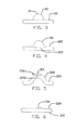
- FIG. 4 is a detailed cross-sectional view of a flexure and load point in accordance with another embodiment of the present invention.
- FIG. 5 is a detailed cross-sectional view of a flexure and load point in accordance with another embodiment of the present invention.
- FIG. 6 is a detailed cross-sectional view of a flexure and load point in accordance with another embodiment of the present invention.
- FIG. 7 is a fragmentary isometric view of a load beam in accordance with another embodiment of the present invention.
- FIG. 8 is a fragmentary isometric view of a head suspension assembly (without slider) incorporating the load beam of FIG. 7 .
- FIG. 9A-9D are detailed cross sections, taken along line 9 - 9 in FIG. 8 , illustrating sequential steps of a process for manufacturing a load point in accordance with an embodiment of the present invention.
- FIG. 10 is a detailed cross-sectional view of a load point structure in accordance with another embodiment of the present invention.
- FIG. 1 is an illustration of a head suspension 12 including a load point 10 in accordance with one embodiment of the present invention.
- suspension 12 includes a stainless steel load beam 14 with a flexure 15 welded or otherwise attached to the load beam.
- Load beams such as 14 are well known and commercially available.
- Load beam 14 includes a mounting region 16 at its proximal end, a relatively rigid region 18 , a load beam load point region 28 and a spring region 20 between the mounting and rigid regions.
- a base plate 17 is welded to the mounting region 16 .
- the flexure 15 is configured to have a slider 70 adhesively bonded or otherwise mounted on the slider mounting region 21 (shown in FIG. 2 ).
- FIG. 2 shows the distal end of flexure 15 in accordance with the present invention.
- Flexure 15 includes a mounting region 26 and gimbal region 34 .
- the mounting region 26 is configured to be attached to the rigid region 18 of the load beam.
- the gimbal region 34 includes flexure load point region 22 , load point 10 , spring arms 30 , and slider mounting region 21 .
- Load point 10 transfers the spring load from the suspension to the slider, provides a point about which the slider gimbals and provides a soft link between the flexure and load beam and serves to isolate vibration propagating from the load beam to the gimbal.
- load point 10 is a mass of viscoelastic damping adhesive such as JDC MP65 from JDC Incorporated, Mount Juliet, Tenn.
- Other materials having vibration isolation properties such as thermoplastics, thermosets, rubbers and ionomers are also contemplated for load point 10 .
- thermoplastics that can be used to form load point 10 include but are not limited to polyacrylates, polycarbonates, polyetherimides, polyesters, polysulfones, polystyrenes, acrylonitrile butadiene styrene block copolymers, polypropylenes, acetal polymers, polyvinyl acetyl polymers, polyamides, polyvinyl chlorides, polyethylenes, polyurethanes, Ethylene-Vinyl Acetate, polyether block amides, thermoplastic vulcanates, thermoplastic elastomers, styrenic elastomers and combinations thereof.
- Examples of rubbers that can be used to form load point 10 include but are not limited to urethane rubbers, silicone rubbers, nitrile rubbers, butyl rubbers, Synthetic rubber, acrylic rubbers, natural rubbers, Chloroprene rubber, Fluoroelastomers, Perfluoroelastomers, EPDM, styrene-butadiene rubbers, polyesters, polyurethanes, polyamides, ethylene-vinyl acetate copolymers, and epoxy-acrylate interpenetrating networks
- FIG. 3 is a cross-sectional view of load point 10 taken along line 3 - 3 in FIG. 2 .
- load point 10 is fixedly engaged with flexure load point region 22 and includes contact region 11 for releasably engaging load beam load point region 28 (i.e. the load point is not bonded to the load beam load point region).
- the illustrated embodiment of load point 10 has a generally circular or cylindrical shape with a generally domed contact region 11 .
- Other embodiments of load point 10 include tear-drop, frustro conical, cubical or other geometric shapes.
- Load point 10 has a diameter of approximately 0.3 mm to 0.6 mm and a height of approximately 0.025 mm to 0.100 mm in one embodiment although other embodiments can be larger or smaller.
- Load point 10 can be a viscoelastic material having a loss factor of 1 to 10 in the operating frequency range of 0 to 40,000 Hz and the operating temperature range of ⁇ 40 to 80 degrees C. Although lower loss factors can be used, a minimum loss factor of 0.1 to 1 within the above frequency and temperature ranges is also contemplated.
- FIG. 4 shows a load point 110 in accordance with another embodiment of the invention.
- flexure load point region 122 includes pocket 123 .
- Pocket 123 serves to aid in locating load point 110 and can be formed by known methods such as by partial etching, laser ablation, mechanical forming or punching.
- Load point 110 can utilize the same material and have similar size and shape to load point 10 but can have other sizes, dimensions and geometric shapes as well.
- pocket 123 has a diameter of approximately 0.3 mm to 0.6 mm although other embodiments can be larger or smaller.
- Pocket 123 can be circular, rectangular, triangular or other geometric shape and is approximately 0.0025 mm-0.010 mm deep. In some embodiments, pocket 123 is no deeper than approximately 50% of the material thickness of load point region 122 .
- FIG. 5 shows a flexure load point region 222 having a load point structure 210 in accordance with an alternate embodiment of the invention.
- Load point structure 210 includes protruded area 224 and viscoelastic contact region 211 .
- protruded area 224 is a formed, generally hemispherical, shape as is known in the art. Alternately, protruded area 224 may be cylindrical, frustro conical, rectangular or other geometric shape and may be formed by etching, stamping, plating or other methods. As shown, protruded area 224 is approximately 0.25 mm-0.90 mm in diameter although other embodiments can be larger or smaller. Protruded area 224 further includes pocket 223 , similar to pocket 123 in FIG.
- Pocket 223 is approximately 0.125 mm-0.50 mm in diameter although other embodiments can be larger or smaller.
- Viscoelastic contact region 211 can be the same material as load point 10 and has a height sufficient to extend above protruded area 224 .
- pocket 223 is approximately 0.005 mm deep and contact region 11 has a height of approximately 0.01 mm. Other embodiments can be larger or smaller.
- FIG. 6 shows load point 310 in accordance with yet another embodiment the invention.
- Load point 310 is a generally flat surface or adhesive damping ‘sheet’ having a generally rectangular, circular or other geometric shape.
- load point 310 has a rectangular shape having sides of approximately 0.3 mm to 0.6 mm and a height of approximately 0.010 mm to 0.025 mm although other embodiments can be larger or smaller.
- FIG. 7 shows a load point 410 located and fixedly engaged on load beam load point region 428 of load beam 414 .
- load point 410 will releasably engage the flexure tongue (not shown).
- load point 410 is similar in size and shape and can utilize the same material as load point 10 but can also be configured similar to load points 110 , 210 or 310 previously described.
- FIG. 8 shows the distal end of head suspension 412 having load beam 414 , flexure 415 and load point 410 .
- spacer 440 is used to space flexure load point region 422 from load beam load point region 428 .
- Dispensing system 442 applies a mass of viscoelastic adhesive material 444 in fluid or gel form to load point region 428 .
- Adhesive dispensing system 442 is removed and material 444 is cured or otherwise solidified by thermal, ultraviolet or other processing to fixedly engage load point 410 with load beam load point region 428 . As shown in FIG. 9C , material 444 may have a ‘tear drop’ shaped resulting from the dispensing process although other shapes are also contemplated. Spacer 440 is then removed and flexure 415 is welded or otherwise attached to load beam 414 as is known in the art. The above processes can also be performed after the flexure 415 is welded or otherwise attached to load beam 414 .
- Another method for manufacturing the load point structures of the present invention is to apply viscoelastic material to the load point regions of the flexure or load beam prior to the flexure-to-load beam assembly process.
- the viscoelastic material is applied in batch form using screen printing, gravure printing, pad printing, pin transfer, fluid dispensing and molding processes or the like.
- the viscoelastic material may be fully cured after application or partially cured after application and followed with a secondary cure after the flexure-to-load beam assembly process.
- Sheet-form or flat load points 310 may also be applied using ‘kiss-cut’ in combination with pick-and-place processes as are generally known.
- the viscoelastic sheet includes a second, sufficiently rigid, layer (not shown) to enable the punch and placement processes.
- Viscoelastic load point 310 is punched from a sheet of viscoelastic material and fixedly engaged to one of the load beam load point region (not shown) and flexure load point region 322 .
- the second layer may be a ‘green’ polymer or other adhesive that is cured after flexure 315 is attached to load beam (not shown) to fixedly engage load point 310 to the other of the flexure load point region 322 and load beam load point region creating a ‘pinned’ load point as described with respect to FIG. 10 below.
- the second layer is a constraint layer that does not go through a curing process after attaching flexure 315 to load beam.
- load point 310 may include multiple layers of viscoelastic material. An example of a structure of this type would be a load point 310 having two different viscoelastic materials configured into three layers.
- the multilayer structure can, for example, include 0.7-mil JDC MD15 ⁇ 0.7-mil JDC MP65 ⁇ 0.7-mil JDC MD15.
- a ‘pinned’ load point 510 is fixedly engaged to both flexure load point region 522 and load beam load point region 528 .
- the illustrated embodiment of ‘pinned’ load point 510 has a generally ‘hour glass’ shape although other shapes and configurations such as those described with respect to load points 10 , 110 , 210 , 310 and 410 are also contemplated.
- the ‘pinned’ load point 510 also helps to reduce the separation between the load beam 514 and flexure 515 during loading and unloading of the head suspension assembly 512 thereby reducing risk of damage to the head suspension assembly 512 .
- Load point 510 can be manufactured in a manner similar to that described above in connection with FIG.
- the viscoelastic material of the load point can be partially cured prior to removing the spacer and then a final cure can be applied after the spacer is removed to fixedly engage or bond the viscoelastic material to both the load beam load point region and the flexure load point region.
Abstract
Description
Claims (4)
Priority Applications (1)
| Application Number | Priority Date | Filing Date | Title |
|---|---|---|---|
| US12/118,240 US8259416B1 (en) | 2008-05-09 | 2008-05-09 | Head suspension having viscoelastic load point |
Applications Claiming Priority (1)
| Application Number | Priority Date | Filing Date | Title |
|---|---|---|---|
| US12/118,240 US8259416B1 (en) | 2008-05-09 | 2008-05-09 | Head suspension having viscoelastic load point |
Publications (1)
| Publication Number | Publication Date |
|---|---|
| US8259416B1 true US8259416B1 (en) | 2012-09-04 |
Family
ID=46726497
Family Applications (1)
| Application Number | Title | Priority Date | Filing Date |
|---|---|---|---|
| US12/118,240 Active 2031-01-04 US8259416B1 (en) | 2008-05-09 | 2008-05-09 | Head suspension having viscoelastic load point |
Country Status (1)
| Country | Link |
|---|---|
| US (1) | US8259416B1 (en) |
Cited By (20)
| Publication number | Priority date | Publication date | Assignee | Title |
|---|---|---|---|---|
| US8760814B1 (en) * | 2013-02-26 | 2014-06-24 | Western Digital Technologies, Inc. | Disk drive head suspension assembly having a DLC coating between dimple and tongue |
| US8891206B2 (en) | 2012-12-17 | 2014-11-18 | Hutchinson Technology Incorporated | Co-located gimbal-based dual stage actuation disk drive suspensions with motor stiffener |
| US8896969B1 (en) | 2013-05-23 | 2014-11-25 | Hutchinson Technology Incorporated | Two-motor co-located gimbal-based dual stage actuation disk drive suspensions with motor stiffeners |
| US8896968B2 (en) * | 2012-10-10 | 2014-11-25 | Hutchinson Technology Incorporated | Co-located gimbal-based dual stage actuation disk drive suspensions with dampers |
| US8896970B1 (en) | 2013-12-31 | 2014-11-25 | Hutchinson Technology Incorporated | Balanced co-located gimbal-based dual stage actuation disk drive suspensions |
| US8941951B2 (en) | 2012-11-28 | 2015-01-27 | Hutchinson Technology Incorporated | Head suspension flexure with integrated strain sensor and sputtered traces |
| US9001469B2 (en) | 2012-03-16 | 2015-04-07 | Hutchinson Technology Incorporated | Mid-loadbeam dual stage actuated (DSA) disk drive head suspension |
| US9001471B2 (en) | 2012-09-14 | 2015-04-07 | Hutchinson Technology Incorporated | Co-located gimbal-based dual stage actuation disk drive suspensions |
| US9007726B2 (en) | 2013-07-15 | 2015-04-14 | Hutchinson Technology Incorporated | Disk drive suspension assembly having a partially flangeless load point dimple |
| US9036302B2 (en) | 2012-08-31 | 2015-05-19 | Hutchinson Technology Incorporated | Damped dual stage actuation disk drive suspensions |
| US9042054B2 (en) | 2013-08-21 | 2015-05-26 | Hutchinson Technology Incorporated | Co-located gimbal-based dual stage actuation disk drive suspensions with offset motors |
| US20150162033A1 (en) * | 2013-12-05 | 2015-06-11 | Hutchinson Technology Incorporated | Constrained dimple pad damper for disk drive head suspension |
| US9070392B1 (en) | 2014-12-16 | 2015-06-30 | Hutchinson Technology Incorporated | Piezoelectric disk drive suspension motors having plated stiffeners |
| US9245555B2 (en) | 2010-05-24 | 2016-01-26 | Hutchinson Technology Incorporated | Low resistance ground joints for dual stage actuation disk drive suspensions |
| US9318136B1 (en) | 2014-12-22 | 2016-04-19 | Hutchinson Technology Incorporated | Multilayer disk drive motors having out-of-plane bending |
| US9431042B2 (en) | 2014-01-03 | 2016-08-30 | Hutchinson Technology Incorporated | Balanced multi-trace transmission in a hard disk drive flexure |
| US9646638B1 (en) | 2016-05-12 | 2017-05-09 | Hutchinson Technology Incorporated | Co-located gimbal-based DSA disk drive suspension with traces routed around slider pad |
| US9734852B2 (en) | 2015-06-30 | 2017-08-15 | Hutchinson Technology Incorporated | Disk drive head suspension structures having improved gold-dielectric joint reliability |
| US9824704B2 (en) | 2015-02-17 | 2017-11-21 | Hutchinson Technology Incorporated | Partial curing of a microactuator mounting adhesive in a disk drive suspension |
| US11393497B2 (en) * | 2020-11-04 | 2022-07-19 | Western Digital Technologies, Inc. | Restriction of suspension dimple contact point |
Citations (27)
| Publication number | Priority date | Publication date | Assignee | Title |
|---|---|---|---|---|
| US3968336A (en) | 1974-09-23 | 1976-07-06 | Xerox Corporation | Keyboard switch assembly having movable contact, and supporting helicline type legs disposed co-planar to common conductive sheet |
| US4167765A (en) | 1978-07-27 | 1979-09-11 | International Business Machines Corporation | Transducer suspension mount apparatus |
| US4853811A (en) * | 1987-08-03 | 1989-08-01 | International Business Machines Corporation | Magnetic disk drive with low profile head-suspension system |
| US4975795A (en) | 1987-12-04 | 1990-12-04 | Digital Equipment Corporation | Electrical connection for a self-loading head assembly for disk drives |
| US4974633A (en) | 1989-12-19 | 1990-12-04 | Hickey John J | System for controlling the flow of a fluid medium relative to an object |
| US5079660A (en) | 1988-07-05 | 1992-01-07 | Mitsubishi Denki Kabushiki Kaisha | Magnetic head suspension assembly for reducing vibration effects |
| US5321568A (en) | 1993-04-22 | 1994-06-14 | Maxtor Corporation | Head suspension assembly with improved pitch and roll characteristics |
| JPH06215511A (en) | 1992-10-07 | 1994-08-05 | Read Rite Corp | Magnetic-head suspension device assembly manufactured so as to be provided with integrated loading beam and flexure |
| US5428490A (en) | 1992-11-12 | 1995-06-27 | Seagate Technology, Inc. | One-piece flexure having an etched load point button |
| US5473488A (en) | 1994-08-03 | 1995-12-05 | Hutchinson Technology Incorporated | Static attitude adjustment via a solidified drop for a magnetic head suspension |
| US5530606A (en) | 1993-08-19 | 1996-06-25 | International Business Machines Corporation | Low profile head suspension assembly |
| US5608590A (en) | 1994-06-20 | 1997-03-04 | Hutchinson Technology Incorporated | Gimballing flexure with static compensation and load print intregal etched features |
| US5796554A (en) | 1997-04-01 | 1998-08-18 | Western Digital Corporation | Load beam assembly with separate spring and hinge functions |
| JPH11339363A (en) | 1998-05-27 | 1999-12-10 | Mitsumi Electric Co Ltd | Magnetic head |
| US6078470A (en) | 1996-06-28 | 2000-06-20 | Hutchinson Technology, Inc. | Head suspension having a modified dimple design |
| US6181522B1 (en) | 1998-12-12 | 2001-01-30 | Read-Write Corporation | Read/write head with a gimbal ball assembly |
| US6212760B1 (en) | 1999-04-28 | 2001-04-10 | Magnecomp Corp. | Alignment of sliders in head gimbal assemblies |
| US6549376B1 (en) * | 2000-03-31 | 2003-04-15 | John E. Scura | Gimbal suspension with vibration damper |
| US20030210499A1 (en) * | 2002-05-07 | 2003-11-13 | International Business Machines Corporation | Damping of vertical and offtrack dynamic modes gain at the slider in a disc drive |
| US6751062B2 (en) | 2001-07-04 | 2004-06-15 | Saesmagnetics (H.K.) Ltd. | Vibration-canceling mechanism and head gimbal assembly with the vibration-canceling mechanism |
| US6765761B2 (en) * | 2002-04-24 | 2004-07-20 | International Business Machines Corp. | Swageless mount plate or unimount arm based milliactuated suspension |
| US6781794B2 (en) | 1999-07-23 | 2004-08-24 | Fujitsu Limited | Head suspension having different hardness contact surfaces for head slider control during shock |
| US7046483B2 (en) | 2002-05-28 | 2006-05-16 | Hitachi Global Storage Technologies Netherlands B.V. | Copper gimbal and gimbal damping for integrated lead suspension |
| US7050267B2 (en) | 2003-03-27 | 2006-05-23 | Samsung Electronics Co., Ltd. | Head-gimbal assembly of hard disk drive |
| EP1691350A1 (en) | 2005-02-09 | 2006-08-16 | Fujitsu Limited | Magnetic head assembly |
| US20070293866A1 (en) | 2006-05-12 | 2007-12-20 | Dieter Stoeckel | Bone anchor system and method of use |
| US7864488B1 (en) * | 2007-03-13 | 2011-01-04 | Western Digital Technologies, Inc. | Suspension assembly including a dimple that contacts a flexure tongue dielectric layer through a hole in a flexure tongue structural layer |
-
2008
- 2008-05-09 US US12/118,240 patent/US8259416B1/en active Active
Patent Citations (28)
| Publication number | Priority date | Publication date | Assignee | Title |
|---|---|---|---|---|
| US3968336A (en) | 1974-09-23 | 1976-07-06 | Xerox Corporation | Keyboard switch assembly having movable contact, and supporting helicline type legs disposed co-planar to common conductive sheet |
| US4167765A (en) | 1978-07-27 | 1979-09-11 | International Business Machines Corporation | Transducer suspension mount apparatus |
| US4853811A (en) * | 1987-08-03 | 1989-08-01 | International Business Machines Corporation | Magnetic disk drive with low profile head-suspension system |
| US4975795A (en) | 1987-12-04 | 1990-12-04 | Digital Equipment Corporation | Electrical connection for a self-loading head assembly for disk drives |
| US5079660A (en) | 1988-07-05 | 1992-01-07 | Mitsubishi Denki Kabushiki Kaisha | Magnetic head suspension assembly for reducing vibration effects |
| US4974633A (en) | 1989-12-19 | 1990-12-04 | Hickey John J | System for controlling the flow of a fluid medium relative to an object |
| JPH06215511A (en) | 1992-10-07 | 1994-08-05 | Read Rite Corp | Magnetic-head suspension device assembly manufactured so as to be provided with integrated loading beam and flexure |
| US5428490A (en) | 1992-11-12 | 1995-06-27 | Seagate Technology, Inc. | One-piece flexure having an etched load point button |
| US5321568A (en) | 1993-04-22 | 1994-06-14 | Maxtor Corporation | Head suspension assembly with improved pitch and roll characteristics |
| US5530606A (en) | 1993-08-19 | 1996-06-25 | International Business Machines Corporation | Low profile head suspension assembly |
| US5608590A (en) | 1994-06-20 | 1997-03-04 | Hutchinson Technology Incorporated | Gimballing flexure with static compensation and load print intregal etched features |
| US5473488A (en) | 1994-08-03 | 1995-12-05 | Hutchinson Technology Incorporated | Static attitude adjustment via a solidified drop for a magnetic head suspension |
| US6078470A (en) | 1996-06-28 | 2000-06-20 | Hutchinson Technology, Inc. | Head suspension having a modified dimple design |
| US5796554A (en) | 1997-04-01 | 1998-08-18 | Western Digital Corporation | Load beam assembly with separate spring and hinge functions |
| JPH11339363A (en) | 1998-05-27 | 1999-12-10 | Mitsumi Electric Co Ltd | Magnetic head |
| US6181522B1 (en) | 1998-12-12 | 2001-01-30 | Read-Write Corporation | Read/write head with a gimbal ball assembly |
| US6212760B1 (en) | 1999-04-28 | 2001-04-10 | Magnecomp Corp. | Alignment of sliders in head gimbal assemblies |
| US6781794B2 (en) | 1999-07-23 | 2004-08-24 | Fujitsu Limited | Head suspension having different hardness contact surfaces for head slider control during shock |
| US6549376B1 (en) * | 2000-03-31 | 2003-04-15 | John E. Scura | Gimbal suspension with vibration damper |
| US6751062B2 (en) | 2001-07-04 | 2004-06-15 | Saesmagnetics (H.K.) Ltd. | Vibration-canceling mechanism and head gimbal assembly with the vibration-canceling mechanism |
| US6765761B2 (en) * | 2002-04-24 | 2004-07-20 | International Business Machines Corp. | Swageless mount plate or unimount arm based milliactuated suspension |
| US20030210499A1 (en) * | 2002-05-07 | 2003-11-13 | International Business Machines Corporation | Damping of vertical and offtrack dynamic modes gain at the slider in a disc drive |
| US7072144B2 (en) | 2002-05-07 | 2006-07-04 | Hitachi Global Storage Technologies Netherlands B.V. | Damping of vertical and offtrack dynamic modes gain at the slider in a disc drive |
| US7046483B2 (en) | 2002-05-28 | 2006-05-16 | Hitachi Global Storage Technologies Netherlands B.V. | Copper gimbal and gimbal damping for integrated lead suspension |
| US7050267B2 (en) | 2003-03-27 | 2006-05-23 | Samsung Electronics Co., Ltd. | Head-gimbal assembly of hard disk drive |
| EP1691350A1 (en) | 2005-02-09 | 2006-08-16 | Fujitsu Limited | Magnetic head assembly |
| US20070293866A1 (en) | 2006-05-12 | 2007-12-20 | Dieter Stoeckel | Bone anchor system and method of use |
| US7864488B1 (en) * | 2007-03-13 | 2011-01-04 | Western Digital Technologies, Inc. | Suspension assembly including a dimple that contacts a flexure tongue dielectric layer through a hole in a flexure tongue structural layer |
Cited By (40)
| Publication number | Priority date | Publication date | Assignee | Title |
|---|---|---|---|---|
| US9812160B2 (en) | 2010-05-24 | 2017-11-07 | Hutchinson Technology Incorporated | Low resistance ground joints for dual stage actuation disk drive suspensions |
| US9245555B2 (en) | 2010-05-24 | 2016-01-26 | Hutchinson Technology Incorporated | Low resistance ground joints for dual stage actuation disk drive suspensions |
| US9001469B2 (en) | 2012-03-16 | 2015-04-07 | Hutchinson Technology Incorporated | Mid-loadbeam dual stage actuated (DSA) disk drive head suspension |
| US9036302B2 (en) | 2012-08-31 | 2015-05-19 | Hutchinson Technology Incorporated | Damped dual stage actuation disk drive suspensions |
| US9001471B2 (en) | 2012-09-14 | 2015-04-07 | Hutchinson Technology Incorporated | Co-located gimbal-based dual stage actuation disk drive suspensions |
| US8896968B2 (en) * | 2012-10-10 | 2014-11-25 | Hutchinson Technology Incorporated | Co-located gimbal-based dual stage actuation disk drive suspensions with dampers |
| US9240203B2 (en) | 2012-10-10 | 2016-01-19 | Hutchinson Technology Incorporated | Co-located gimbal-based dual stage actuation disk drive suspensions with dampers |
| US8941951B2 (en) | 2012-11-28 | 2015-01-27 | Hutchinson Technology Incorporated | Head suspension flexure with integrated strain sensor and sputtered traces |
| US8891206B2 (en) | 2012-12-17 | 2014-11-18 | Hutchinson Technology Incorporated | Co-located gimbal-based dual stage actuation disk drive suspensions with motor stiffener |
| US9257139B2 (en) | 2012-12-17 | 2016-02-09 | Hutchinson Technology Incorporated | Co-located gimbal-based dual stage actuation disk drive suspensions with motor stiffeners |
| US8760814B1 (en) * | 2013-02-26 | 2014-06-24 | Western Digital Technologies, Inc. | Disk drive head suspension assembly having a DLC coating between dimple and tongue |
| US10629232B2 (en) | 2013-05-23 | 2020-04-21 | Hutchinson Technology Incorporated | Two-motor co-located gimbal-based dual stage actuation disk drive suspensions with motor stiffeners |
| US9997183B2 (en) | 2013-05-23 | 2018-06-12 | Hutchinson Technology Incorporated | Two-motor co-located gimbal-based dual stage actuation disk drive suspensions with motor stiffeners |
| US8896969B1 (en) | 2013-05-23 | 2014-11-25 | Hutchinson Technology Incorporated | Two-motor co-located gimbal-based dual stage actuation disk drive suspensions with motor stiffeners |
| US9613644B2 (en) | 2013-05-23 | 2017-04-04 | Hutchinson Technology Incorporated | Two-motor co-located gimbal-based dual stage actuation disk drive suspensions with motor stiffeners |
| US9524739B2 (en) | 2013-07-15 | 2016-12-20 | Hutchinson Technology Incorporated | Disk drive suspension assembly having a partially flangeless load point dimple |
| US10002629B2 (en) | 2013-07-15 | 2018-06-19 | Hutchinson Technology Incorporated | Disk drive suspension assembly having a partially flangeless load point dimple |
| US9007726B2 (en) | 2013-07-15 | 2015-04-14 | Hutchinson Technology Incorporated | Disk drive suspension assembly having a partially flangeless load point dimple |
| US9870792B2 (en) | 2013-07-15 | 2018-01-16 | Hutchinson Technology Incorporated | Disk drive suspension assembly having a partially flangeless load point dimple |
| US9042054B2 (en) | 2013-08-21 | 2015-05-26 | Hutchinson Technology Incorporated | Co-located gimbal-based dual stage actuation disk drive suspensions with offset motors |
| US20150162033A1 (en) * | 2013-12-05 | 2015-06-11 | Hutchinson Technology Incorporated | Constrained dimple pad damper for disk drive head suspension |
| US9330697B2 (en) * | 2013-12-05 | 2016-05-03 | Hutchinson Technology Incorporated | Constrained dimple pad damper for disk drive head suspension |
| US9147413B2 (en) | 2013-12-31 | 2015-09-29 | Hutchinson Technology Incorporated | Balanced co-located gimbal-based dual stage actuation disk drive suspensions |
| US8896970B1 (en) | 2013-12-31 | 2014-11-25 | Hutchinson Technology Incorporated | Balanced co-located gimbal-based dual stage actuation disk drive suspensions |
| US9431042B2 (en) | 2014-01-03 | 2016-08-30 | Hutchinson Technology Incorporated | Balanced multi-trace transmission in a hard disk drive flexure |
| US9715890B2 (en) | 2014-12-16 | 2017-07-25 | Hutchinson Technology Incorporated | Piezoelectric disk drive suspension motors having plated stiffeners |
| US9558771B2 (en) | 2014-12-16 | 2017-01-31 | Hutchinson Technology Incorporated | Piezoelectric disk drive suspension motors having plated stiffeners |
| US10002628B2 (en) | 2014-12-16 | 2018-06-19 | Hutchinson Technology Incorporated | Piezoelectric motors including a stiffener layer |
| US9070392B1 (en) | 2014-12-16 | 2015-06-30 | Hutchinson Technology Incorporated | Piezoelectric disk drive suspension motors having plated stiffeners |
| US9564154B2 (en) | 2014-12-22 | 2017-02-07 | Hutchinson Technology Incorporated | Multilayer disk drive motors having out-of-plane bending |
| US10339966B2 (en) | 2014-12-22 | 2019-07-02 | Hutchinson Technology Incorporated | Multilayer disk drive motors having out-of-plane bending |
| US9318136B1 (en) | 2014-12-22 | 2016-04-19 | Hutchinson Technology Incorporated | Multilayer disk drive motors having out-of-plane bending |
| US9824704B2 (en) | 2015-02-17 | 2017-11-21 | Hutchinson Technology Incorporated | Partial curing of a microactuator mounting adhesive in a disk drive suspension |
| US10147449B2 (en) | 2015-02-17 | 2018-12-04 | Hutchinson Technology Incorporated | Partial curing of a microactuator mounting adhesive in a disk drive suspension |
| US10290313B2 (en) | 2015-06-30 | 2019-05-14 | Hutchinson Technology Incorporated | Disk drive head suspension structures having improved gold-dielectric joint reliability |
| US9734852B2 (en) | 2015-06-30 | 2017-08-15 | Hutchinson Technology Incorporated | Disk drive head suspension structures having improved gold-dielectric joint reliability |
| US10748566B2 (en) | 2015-06-30 | 2020-08-18 | Hutchinson Technology Incorporated | Disk drive head suspension structures having improved gold-dielectric joint reliability |
| US10109305B2 (en) | 2016-05-12 | 2018-10-23 | Hutchinson Technology Incorporated | Co-located gimbal-based DSA disk drive suspension with traces routed around slider pad |
| US9646638B1 (en) | 2016-05-12 | 2017-05-09 | Hutchinson Technology Incorporated | Co-located gimbal-based DSA disk drive suspension with traces routed around slider pad |
| US11393497B2 (en) * | 2020-11-04 | 2022-07-19 | Western Digital Technologies, Inc. | Restriction of suspension dimple contact point |
Similar Documents
| Publication | Publication Date | Title |
|---|---|---|
| US8259416B1 (en) | Head suspension having viscoelastic load point | |
| US6160684A (en) | Head suspension having tabs and force isolation welds for gram load reduction during swaging | |
| US6512657B2 (en) | Head suspension having gram load change reduction and method of assembly | |
| US8120878B1 (en) | Tubular stiffening rails for head suspension components | |
| US7701675B2 (en) | Micro-actuator mounting structure capable of maintaining a substantially constant gap between a top support of a micro-actuator and a suspension during use | |
| US8885294B2 (en) | Head gimbal assembly and disk device with the same | |
| US7660079B2 (en) | Method and system of using a step plate mechanically formed in a disk drive suspension flexure to mount a micro-actuator to the flexure | |
| KR100440374B1 (en) | Low mass disc drive suspension | |
| JP2007257824A (en) | Suspension, head gimbal assembly equipped therewith and disk unit | |
| JP2001023323A (en) | Positive gram controlled suspension for disk drive | |
| US8976491B1 (en) | Disk drive head suspension distal non-op shock limiter with branched arms | |
| US9047896B1 (en) | Head assembly and disk device provided with the same | |
| US9093089B1 (en) | Suspension assembly, head suspension assembly and disk device with the same | |
| JP2001140977A (en) | Base isolation support body | |
| US9070391B1 (en) | Reduced-thickness baseplate | |
| JP4866759B2 (en) | Flexures with controlled static posture and load point contact | |
| US5973885A (en) | Swageable base for suspension assembly in hard disk drive without flange | |
| JP2007043789A (en) | Microactuator, head gimbal assembly using it, hard disc drive, its manufacturing method | |
| US20080002304A1 (en) | Micro-actuator mounting arrangement and manufacturing method thereof | |
| WO2015134325A1 (en) | Swage mount for hard disk drives | |
| US10367135B2 (en) | Method of fabricating a base plate for piezo actuation | |
| US7190554B2 (en) | Magnetic head suspension | |
| US20050190502A1 (en) | Head suspension assembly having a high damping high stiffness component | |
| JP5431024B2 (en) | Disk drive | |
| US7113370B2 (en) | Slanted mounting for preload flat suspension |
Legal Events
| Date | Code | Title | Description |
|---|---|---|---|
| AS | Assignment |
Owner name: HUTCHINSON TECHNOLOGY INCORPORATED, MINNESOTA Free format text: ASSIGNMENT OF ASSIGNORS INTEREST;ASSIGNORS:DAVIS, MICHAEL W.;KAZEMI, MOHAMMED;LOWRY, MARK G.;AND OTHERS;REEL/FRAME:020928/0015 Effective date: 20080509 |
|
| STCF | Information on status: patent grant |
Free format text: PATENTED CASE |
|
| FPAY | Fee payment |
Year of fee payment: 4 |
|
| MAFP | Maintenance fee payment |
Free format text: PAYMENT OF MAINTENANCE FEE, 8TH YEAR, LARGE ENTITY (ORIGINAL EVENT CODE: M1552); ENTITY STATUS OF PATENT OWNER: LARGE ENTITY Year of fee payment: 8 |
|
| MAFP | Maintenance fee payment |
Free format text: PAYMENT OF MAINTENANCE FEE, 12TH YEAR, LARGE ENTITY (ORIGINAL EVENT CODE: M1553); ENTITY STATUS OF PATENT OWNER: LARGE ENTITY Year of fee payment: 12 |