US8079634B2 - Sealed AFT cavity drag reducer - Google Patents
Sealed AFT cavity drag reducer Download PDFInfo
- Publication number
- US8079634B2 US8079634B2 US11/586,489 US58648906A US8079634B2 US 8079634 B2 US8079634 B2 US 8079634B2 US 58648906 A US58648906 A US 58648906A US 8079634 B2 US8079634 B2 US 8079634B2
- Authority
- US
- United States
- Prior art keywords
- panels
- panel
- vehicle
- base panel
- sealing
- Prior art date
- Legal status (The legal status is an assumption and is not a legal conclusion. Google has not performed a legal analysis and makes no representation as to the accuracy of the status listed.)
- Expired - Fee Related
Links
- 239000003638 chemical reducing agent Substances 0.000 title description 3
- 238000000034 method Methods 0.000 claims description 54
- 238000007789 sealing Methods 0.000 claims description 29
- 239000000463 material Substances 0.000 claims description 24
- 239000002131 composite material Substances 0.000 claims description 7
- 239000000835 fiber Substances 0.000 claims description 6
- 229920000049 Carbon (fiber) Polymers 0.000 claims description 5
- XAGFODPZIPBFFR-UHFFFAOYSA-N aluminium Chemical compound [Al] XAGFODPZIPBFFR-UHFFFAOYSA-N 0.000 claims description 5
- 229910052782 aluminium Inorganic materials 0.000 claims description 5
- 239000004917 carbon fiber Substances 0.000 claims description 5
- VNWKTOKETHGBQD-UHFFFAOYSA-N methane Chemical compound C VNWKTOKETHGBQD-UHFFFAOYSA-N 0.000 claims description 5
- 239000002023 wood Substances 0.000 claims description 5
- 230000008878 coupling Effects 0.000 claims 6
- 238000010168 coupling process Methods 0.000 claims 6
- 238000005859 coupling reaction Methods 0.000 claims 6
- 238000013461 design Methods 0.000 abstract description 6
- 230000000694 effects Effects 0.000 abstract description 4
- 238000000926 separation method Methods 0.000 abstract 1
- 230000009467 reduction Effects 0.000 description 16
- 239000000446 fuel Substances 0.000 description 6
- 230000007246 mechanism Effects 0.000 description 5
- 238000012360 testing method Methods 0.000 description 4
- 238000012384 transportation and delivery Methods 0.000 description 4
- 238000012986 modification Methods 0.000 description 3
- 230000004048 modification Effects 0.000 description 3
- 238000011160 research Methods 0.000 description 2
- 238000012552 review Methods 0.000 description 2
- 238000009825 accumulation Methods 0.000 description 1
- 230000002411 adverse Effects 0.000 description 1
- 238000013459 approach Methods 0.000 description 1
- 230000015572 biosynthetic process Effects 0.000 description 1
- 230000001419 dependent effect Effects 0.000 description 1
- 231100001261 hazardous Toxicity 0.000 description 1
- 239000003550 marker Substances 0.000 description 1
- 230000003071 parasitic effect Effects 0.000 description 1
- 238000007493 shaping process Methods 0.000 description 1
- 239000013585 weight reducing agent Substances 0.000 description 1
Images


Classifications
-
- B—PERFORMING OPERATIONS; TRANSPORTING
- B62—LAND VEHICLES FOR TRAVELLING OTHERWISE THAN ON RAILS
- B62D—MOTOR VEHICLES; TRAILERS
- B62D35/00—Vehicle bodies characterised by streamlining
- B62D35/001—For commercial vehicles or tractor-trailer combinations, e.g. caravans
- B62D35/004—Inflatable nose or rear cones
-
- B—PERFORMING OPERATIONS; TRANSPORTING
- B62—LAND VEHICLES FOR TRAVELLING OTHERWISE THAN ON RAILS
- B62D—MOTOR VEHICLES; TRAILERS
- B62D35/00—Vehicle bodies characterised by streamlining
- B62D35/001—For commercial vehicles or tractor-trailer combinations, e.g. caravans
Definitions
- This invention relates to drag reduction on vehicles, such as tractor trailer combinations, delivery vehicles, recreational vehicles, buses, vans or any vehicle that has an inherently blunt or flat aft face, and the attachment of aft devices and more particularly to open aft cavities used in such devices and the means to attach and stow such a device for minimum impact on loading and unloading.
- Mason and Beebe surmised that the added drag of the turning vanes outweighed any gain from increased base pressure. The only device that showed positive results was the non-ventilated cavity design. Mason and Beebe varied the depth of the panels and found an optimum panel length of 0.55 m (21.8 inches) for a conventional 14.6 m (48 foot) trailer yielding an overall drag reduction of 5 percent.
- U.S. Pat. No. 4,236,745 utilizes the concept of a retractable or collapsible device of the fully enclosed surface type.
- the present proposed device is also collapsible, but not of the fully enclosed variety.
- Lechner, U.S. Pat. No. 5,375,903 (1994) also puts forth a self inflatable concept with stiffening supports. However this is also of the enclosed variety.
- U.S. Pat. No. 4,142,755 by Keedy (1979) describes a class of aft devices that reduce the width and height of the aft end of the trailer with panels or surfaces to try to keep the flow attached to the proposed surface reducing the wake width and associated drag.
- the device of this disclosure is of the class of open-ended aft cavities.
- Mulholland in U.S. Pat. No. 4,458,936 (1984), employs rigid panels attached with hinged mechanisms to the rear of the trailer. These outer surfaces join together to form an apex behind the vehicle.
- the concept disclosed herein uses panels that can hinge if desired, but do not join together to form an enclosed exterior surface.
- U.S. Pat. No. 4,682,808 was filed by Bilanin in 1985 on a variation of the cavity design concept that inset the end panels from the trailer perimeter. His claims indicated a drag reduction on the order of 10% is claimed.
- the Bilanin device includes three or four panels oriented in a box formation. Three of the panels (top and sides) are generally inset from the perimeter of the trailer base and that the bottom panel has no inset and is in line with the bottom of the trailer. All the panels are mounted perpendicular to the trailer base, however the Bilian patent does allow for inset angled side panels. This orientation of panels produces vortex structures in the area between the panel and the perimeter of the trailer in the manner of the intent of the Mason and Beebe splitter devices.
- Bilanin claims that a 10.2% reduction in drag was achieved on a typical tractor-trailer with a base tractor-trailer C D of 0.6, however no test results have been published in the literature.
- Bilanin also specifies that the length of the plates should be between 40′′ and 56′′.
- the disclosure described herein can use angled panels in the dimensional ranges specified by Bilanin, but the panels are not inset from the edge, as per Bilanin, and in particular, the resulting cavity for the present design is not one but two separately sealed cavities that enable a viable device for real world applications.
- U.S. Pat. No. 6,485,087 in the name of Roberge (2002) depicts a three sided non-ventilated cavity formed from angled fins off the rear of the trailer, aligned with the edge of the trailer.
- the present concept also utilizes angled fins set to the trailer edge, however, a completely enclosed cavity is formed once the device is deployed, which is further subdivided using eight fins to form two separate and sealed cavities.
- the method for storage of the device by Roberge places it between the opened doors and the sides of the trailer during loading and unloading. This requires a trailer with doors configured to provide clearance for said device.
- the present device strategy does not have this constraint.
- no method of sealing the adjoining panels or of sealing the panels to the rear of the trailer is mentioned by Roberge.
- the present concept requires a sealed cavity to be effective.
- the disclosed device uses a different approach to drag reduction and attachment methods, which, to the best of the authors' knowledge, has not previously been recognized.
- the disclosed device requires the rear cavity(ies) to be completely sealed and this is crucial to the functionality of the device.
- the current device also employs a unique method of stowage which can be used with rigid sided or collapsible sided devices and requires two separately sealed cavities.
- the object of the present invention is concerned with providing an air drag-reducing device which overcomes the above-described problem. More specifically, this is achieved by providing an device which allows the panels to be moved outwardly from a drag reducing position to a position where the doors are in their fully retracted position adjacent to their associated sides of the vehicle.
- a further object of the present invention is to provide a mechanism which will enable the panels to return back to their drag reducing position whenever the doors are hingedly moved from their retracted position to their end closing position.
- the present invention therefore relates to an air drag reducing device for use with a vehicle having top and opposite lateral sides contiguous with a rear end formed of a pair of hingedly mounted rectangular doors movable from a closed position to an open position wherein the doors panels are respectively retracted adjacent to a corresponding side of the vehicle.
- the device has two sealed cavities and means associated with the cavities for positioning the cavities in a drag reducing position rearwardly of a corresponding closed door, wherein the side and top panels define an exemplary angle of about 15 degrees with the rearward projection of the cavities of the corresponding side of the vehicle while the bottom panel has an exemplary angle of approximately 7 degrees.
- Positioning means allow the cavities to be moved between the door and the vehicle side as the door is opened and moved to its retracted position.
- the disclosed invention is an aft cavity drag reduction device for a vehicle with one or more cavities facing aft when in a deployed state.
- the cavities have a hinge and latch system by which the collapsed cavity(ies) are allowed to rotate near, or at, the centerline of the vehicle body, along the opening edge of one or more rear doors, and swing open with said door to lie alongside the vehicle when open into a retracted position.
- the cavities have a base panel; an outside panel; an inside panel; two other panels; and an open area.
- the cavities have a frustum shape with the inside panel normal to said base panel and the outside panel and the two other panels mounted at an angle less than normal with respect to the base panel so as to produce a open area with a smaller foot print than the base panel.
- the base panel is fastened, hinged and sealed to the outside panel, the inside panel, and the two other panels.
- the outside panel and the inside panel are also fastened and sealed to the two other panels.
- the outside panel and the two other panels are mounted at an angle between 0 degrees and 35 degrees.
- the outside panels and a first of the two other panels are mounted at an angle of 15 degrees (exemplary value) with respect to the base panel.
- the second of two other panels are mounted at an angle of 7 degrees (exemplary value) with respect to the base panel.
- the panels are made are made of a light rigid material such as: a composite fiber, a rigid plastic material; carbon fiber; aluminum; or wood.
- the seals are generally bulb type seals.
- the side panels and other panels are unfastened and the seals are broken when the device is put into a collapsed or retracted position.
- the cavities may be fastened and sealed between the respective inside panels when device is put into a deployed position.
- the disclosed invention is also a method of drag reduction for a vehicle including: providing one or more aft facing cavities; mounting the cavities on to an aft portion of a vehicle body; and operating the cavities in a deployed position.
- the method further includes folding the cavities into a substantially flat collapsed position and operating the cavities in the collapsed position.
- the method further includes rotating the cavity(ies) in a collapsed position about a line near, or at, a centerline of the vehicle body, along the opening edge of one or more rear doors, and swinging the cavity(ies) with the doors to lie in a retracted position alongside the vehicle when open.
- Each cavity has: a base panel; an outside panel; an inside panel; two other panels; and an open area.
- the method further includes mounting the inside panel normal to the base panel; mounting the outside panel and the two other panels to the base panel at an angle less than normal with respect to the base panel so as to produce an open area with a smaller foot print than the base panel.
- the outside panel and the two other panels are mounted at an angle between 0 degrees and 35 degrees with respect to the base panel.
- the outside panels and a first of the two other panels are mounted at an angle of 15 degrees (exemplary value) with respect to the base panel.
- the second of two other panels are mounted at an angle of 7 degrees with respect to the base panel.
- the panels are made are made of a light rigid material such as: a composite fiber, a rigid plastic material; carbon fiber; aluminum; or wood.
- the method further includes: fastening and sealing the base panel to the outside panel; fastening and sealing the base panel to the inside panel; fastening and sealing the base panel to the two other panels; and fastening and sealing the outside panel and the inside panel to the two other panels.
- the method further includes unfastening the panels and breaking the seal when the device is put into the collapsed position or the retracted position.
- the method further includes fastening the panels and sealing the panels when the device is put into the deployed position.
- FIG. 1 illustrates a rear view of a truck or trailer without any drag reduction mounted hereon
- FIG. 2 illustrates the device in its deployed state for maximum drag reduction
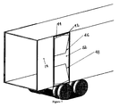
- FIG. 3 illustrates an isometric view of FIG. 2 of the device in its deployed state
- FIG. 4 illustrates a rear view of the device completely retracted wherein there is no hindrance of access to the load within the vehicle
- FIGS. 5 through 7 illustrate a sequence of views as the device moves from its deployed state as illustrated in FIG. 3 to its retracted state as illustrated in FIG. 7 ;
- FIGS. 8 a and 8 b illustrate an isometric view of FIG. 2 with detail of sealed edges.
- the invention comprises a device attached to the rear of any relatively blunt based vehicle including, but not limited to tractor trailer combinations, delivery vehicles, recreational vehicles and buses, vans or any vehicle that has any vehicle that has an inherently blunt or flat aft face.
- the aft of the vehicle is unmodified except to act an attachment point for the device.
- the device when deployed forms one or more sealed aft cavities that extend from the body of the vehicle rearward while maintaining legal length limits.
- the device When the rear doors of the vehicle are opened the device stows in such a way to have no impact on the normal operation of the vehicle. With the rear doors closed the device can be deployed or remain in a collapsed condition to facilitate parking and maneuvering.
- the device itself consists of either rigid fins constructed of traditional rigid materials, including composite materials, or of a flexible materials inflated via the trucks air system, any of which, when deployed, acts to form a sealed open cavity on the aft face and open to the aft direction. Utilizing an inflatable system eliminates majority of the work required to stow the device for loading and unloading of the trailer.
- a key aspect of the design is the framework of the device which attaches to and is hinged to the edge of each door near the centerline of the trailer.
- FIG. 1 illustrates a rear view of a trailer or truck 10 without a drag reduction device having doors 12 and 14 of rectangular shape in a closed position.
- the doors are respectfully mounted by means of hinges 16 on one side and 24 on the other side so as to move from their shown closed position to a fully retracted position where they are disposed parallel and adjacent to the opposite sides 20 and 22 of the vehicle.
- the present invention is concerned with providing, at the rear of vehicle, an air drag reducing device 24 which includes a pair of cavities 26 and 28 .
- a first cavity 26 a left hand cavity, has a generally elongated rectangular shape with an outside edge 30 and an inside edge 32 (defining the long sides of the rectangle) and a pair of opposite sides 34 (at the top of the vehicle) and 48 (at the floor level of the vehicle) (defining the short sides of the rectangle).
- the first cavity has an open area 38 and a base panel 40 . Each of these items, except the open area 38 ( 30 , 32 , 34 and 36 ) are defined as panels.
- the first cavity 26 has a frustum shape (a bath tub like structure), four sides, a base and an open face. The base of the cavity is fastened to a supporting member 15 at the intersection of the base panel 40 and the inside panel 32 .
- the other cavity 28 a right cavity, as illustrated in FIG. 2 has a generally elongated rectangular shape with an outside edge 42 and an inside edge 44 (defining the long sides of the rectangle) and a pair of opposite sides 46 (at the top of the vehicle) and 48 (at the floor level of the vehicle) (defining the short sides of the rectangle).
- the right cavity has an open area 50 and a base panel 52 .
- Each of these items, except the open area 50 ( 42 , 44 , 46 and 48 ) are defined as panels.
- the right cavity 28 has a frustum shape (a bath tub like structure), four sides, a base and an open face. The base of the cavity is fastened to a supporting member 15 at the intersection of the base panel 52 and the inside panel 56 .
- cavities are preferably made of a light rigid material, such as a fiber composite material or a rigid plastic.
- a light rigid material such as a fiber composite material or a rigid plastic.
- aerodynamic devices such as the cavities do not extend more than 5 feet beyond the vehicle and provided they do not have the strength, rigidity, or mass to damage a vehicle or injure a vehicle or in a vehicle that strikes a trailer so equipped from the rear. Additionally, such devices may not obscure tail lamps, turn signals, marker lamps, identification lamps, or any other required safety devices such as hazardous safety placards or conspicuity markings.
- the panels of are made of a light rigid material such as: a composite fiber, a rigid plastic material; carbon fiber; aluminum; or wood.
- the performance of the cavities as a drag reduction system is very dependent upon the sealing of all panel edges in cavities 26 and 28 .
- This sealing can be done by using ordinary bulb type seals, locking seals or a variety of sealing clamp strategies. The sealing needs to breakable when the cavities are moved to their storage positions, as discussed below.
- FIGS. 8 a and 8 b illustrate the nature of the sealing of the right aft cavity.
- Panel 42 is sealed to panel 46 with seal 54 .
- Panel 44 is sealed to panel 46 with seal 56 .
- Similar sealing takes place the interfaces between panel 46 and base panel 28 ; the bottom panel 48 ; and the bottom panel 48 and panels 42 and 54 .
- Similar sealing is done between the same panels in the left cavity.
- Examples of possible sealing arrangement include a seal of the form of a bulb seal 58 or inside edge seal 60 or a similar seal that prevents any air from leaking from the cavity formed by the aft extending panels to the surrounding outer surface except out the aft open end of the cavity
- FIG. 3 illustrates an isometric view of the drag reducing device 10 .
- Inside side panel 32 of left cavity 26 and inside side panel 44 of right cavity 28 are normal to the back of the vehicle and are in contact with each other.
- the base panel 40 and 52 of each cavity is fastened to a supporting member 15 .
- the outside side panels 30 and 42 of each cavity 26 and 28 and the short side panels 34 , 36 , 46 , and 48 may be angled inwardly in the range of 0 to 35 degrees, depending on the preferred geometry.
- An exemplary value for the outside panels 30 and 42 and the upper short side panels 34 and 46 is an angle of about 15 degrees.
- An exemplary value for the short side panels 36 and 48 is an angle of about 7 degrees. It is not required that all panels be angled the same amount.
- cavities 26 and 28 need to have an open area facing rearward and have the sealed panel junctions as discussed above.
- Each cavity has the base panel hinged to the inside panel, outside panel and the other two panels.
- the inside panel and the outside panel of each cavity is fastened to the two other panels.
- FIG. 4 depicts the device in the fully retracted state. Cavity 26 with its panels fold flat along the left side of the vehicle and in front of rear door 12 . Cavity 28 with its panels fold flat along the left side of the vehicle and in front of rear door 14 .
- FIG. 5 to FIG. 7 This motion is illustrated in FIG. 5 to FIG. 7 and contrasts with previous designs which tend to have hinge lines at or near the door hinge line.
- Access to the vehicle is now possible and unchanged from the original vehicle configuration. After load access is complete the rear doors are closed, the devices is placed into its original position and the panels are deployed. Additionally, there may be instances when it would be desirable to have the vehicle's doors closed, but have the drag reducing apparatus in a stowed position. Such instances include being in a crowded business district where multiple deliveries are being made and at the lower speed of travel with the inconvenience of moving the apparatus for each delivery outweighs any marginal fuel efficiency gain by use of the device. The user would use steps a. and b. of the first above described procedures. It is estimated that it takes 5 minutes to move the cavities from the deployed state and the retracted state.
Abstract
Description
D/W=0.13,G/H=0.15,D/L=G/L=0.3
where
0.1≦D/W≦0.2,0.1≦G/H≦0.2,0.2≦D/L=G/L≦0.4
-
- a. Fasteners are released and seals broken allowing the cavity to be folded together;
- b. Sides and top and base of each cavity are folded together against the respective back doors;
- c. Cavity units are released from door and swing out on hinge lines near the centerline of the vehicle;
- d. Vehicle door is opened and released from vehicle; and
- e. Entire assembly swings out of the way on the door hinge line whilst the cavity highline continues to move and then flat against the vehicle side.
-
- a. Cavity units are released from door and swing out on hinge lines near the centerline of the vehicle;
- b. Vehicle door is opened and released from vehicle; and
- c. Entire assembly swings out of the way on the door hinge line whilst the cavity highline continues to move and then against the vehicle side;
- d. Fasteners are released and seals broken allowing the cavity to be folded together;
- e. Sides and top and base of each cavity are folded together against the respective side of the vehicle.
-
- a. Air valve for each separate cavity unit is released;
- b. Cavity units are deflated;
- c. Cavity units are released from door and swing out if necessary or simply remain attached to the door and reside against the door;
- d. Vehicle door is opened and released from vehicle; and
- e. Entire assembly swings out of the way and then flat against the vehicle side.
Claims (40)
Priority Applications (3)
| Application Number | Priority Date | Filing Date | Title |
|---|---|---|---|
| US11/586,489 US8079634B2 (en) | 2005-10-26 | 2006-10-25 | Sealed AFT cavity drag reducer |
| US13/327,920 US8641126B2 (en) | 2005-10-26 | 2011-12-16 | Sealed aft cavity drag reducer |
| US13/329,311 US20120086233A1 (en) | 2005-10-26 | 2011-12-18 | Sealed aft cavity drag reducer |
Applications Claiming Priority (2)
| Application Number | Priority Date | Filing Date | Title |
|---|---|---|---|
| US73002805P | 2005-10-26 | 2005-10-26 | |
| US11/586,489 US8079634B2 (en) | 2005-10-26 | 2006-10-25 | Sealed AFT cavity drag reducer |
Related Child Applications (2)
| Application Number | Title | Priority Date | Filing Date |
|---|---|---|---|
| US13/327,225 Continuation US8879576B2 (en) | 2005-10-26 | 2011-12-15 | Method and apparatus for unlicensed band operation |
| US13/327,920 Division US8641126B2 (en) | 2005-10-26 | 2011-12-16 | Sealed aft cavity drag reducer |
Publications (2)
| Publication Number | Publication Date |
|---|---|
| US20110221231A1 US20110221231A1 (en) | 2011-09-15 |
| US8079634B2 true US8079634B2 (en) | 2011-12-20 |
Family
ID=44559265
Family Applications (3)
| Application Number | Title | Priority Date | Filing Date |
|---|---|---|---|
| US11/586,489 Expired - Fee Related US8079634B2 (en) | 2005-10-26 | 2006-10-25 | Sealed AFT cavity drag reducer |
| US13/327,920 Expired - Fee Related US8641126B2 (en) | 2005-10-26 | 2011-12-16 | Sealed aft cavity drag reducer |
| US13/329,311 Abandoned US20120086233A1 (en) | 2005-10-26 | 2011-12-18 | Sealed aft cavity drag reducer |
Family Applications After (2)
| Application Number | Title | Priority Date | Filing Date |
|---|---|---|---|
| US13/327,920 Expired - Fee Related US8641126B2 (en) | 2005-10-26 | 2011-12-16 | Sealed aft cavity drag reducer |
| US13/329,311 Abandoned US20120086233A1 (en) | 2005-10-26 | 2011-12-18 | Sealed aft cavity drag reducer |
Country Status (1)
| Country | Link |
|---|---|
| US (3) | US8079634B2 (en) |
Cited By (20)
| Publication number | Priority date | Publication date | Assignee | Title |
|---|---|---|---|---|
| US20120086234A1 (en) * | 2005-10-26 | 2012-04-12 | Clarkson University | Sealed aft cavity drag reducer |
| US20120104792A1 (en) * | 2007-05-17 | 2012-05-03 | Advanced Transit Dynamics, Inc. | Rear-mounted aerodynamic structure for truck cargo bodies |
| US20120126572A1 (en) * | 2008-11-06 | 2012-05-24 | Volvo Lastvagnar Ab | Aerodynamic device for a vehicle |
| US20120261945A1 (en) * | 2011-04-14 | 2012-10-18 | Lonnie Litchfield | Apparatus for reducing drag on a vehicle |
| US8579360B2 (en) | 2009-07-29 | 2013-11-12 | Lonnie Litchfield | Apparatus for reducing drag on a vehicle |
| US8770649B2 (en) | 2011-10-29 | 2014-07-08 | Alexander Praskovsky | Device, assembly, and system for reducing aerodynamic drag |
| US20140367993A1 (en) * | 2013-06-18 | 2014-12-18 | Thomas Scott Breidenbach | Aerodynamic drag reducing apparatus |
| US8985677B2 (en) | 2012-11-07 | 2015-03-24 | StormBlok Systems, Inc. | Vehicle fuel economy system |
| US20150274220A1 (en) * | 2012-06-19 | 2015-10-01 | Aerovolution Corporation | Apparatuses, assemblies, and methods for drag reduction of land vehicles |
| US9333993B2 (en) | 2013-06-27 | 2016-05-10 | Aerovolution Corporation | Self-deploying apparatuses, assemblies, and methods for drag reduction of land vehicles |
| US9346496B2 (en) | 2005-12-01 | 2016-05-24 | Stemco Lp | Aerodynamic drag reducing apparatus |
| US9440688B2 (en) | 2011-09-20 | 2016-09-13 | Stemco Lp | Rear-mounted retractable aerodynamic structure for cargo bodies |
| US9457847B2 (en) | 2011-10-27 | 2016-10-04 | Stemco Lp | Rear-mounted aerodynamic structures for cargo bodies |
| US9650086B1 (en) * | 2016-09-20 | 2017-05-16 | Raimund Pfaff | Drag reduction apparatus for a trailer |
| US20170176002A1 (en) * | 2015-12-18 | 2017-06-22 | Eric Williamson | Portable Chimney System |
| US9815507B2 (en) | 2005-06-29 | 2017-11-14 | Thomas Scott Breidenbach | Aerodynamic drag reducing apparatus |
| US9971356B2 (en) | 2012-07-11 | 2018-05-15 | Stemco Products, Inc. | Retractable aerodynamic structures for cargo bodies and methods of controlling positioning of the same |
| US10220889B2 (en) | 2007-05-17 | 2019-03-05 | Stemco Products, Inc. | Rear-mounted aerodynamic structure for truck cargo bodies |
| US20190202505A1 (en) * | 2016-09-05 | 2019-07-04 | OGAB Ltd. | Active drag-reduction system and a method of reducing drag experienced by a vehicle |
| US10953932B2 (en) | 2012-11-07 | 2021-03-23 | Ekostinger, Inc. | Multicomponent improved vehicle fuel economy system |
Families Citing this family (13)
| Publication number | Priority date | Publication date | Assignee | Title |
|---|---|---|---|---|
| US8196994B2 (en) * | 2009-10-26 | 2012-06-12 | Thermaflow Energy Technology, Inc. | Rotationally supporting structure of vehicle's drag-reducing apparatus |
| ES2529513B2 (en) * | 2013-07-19 | 2015-12-29 | Universidad de Córdoba | REDUCING DEVICE OF AERODYNAMIC RESISTANCE IN VEHICLES |
| US9199675B2 (en) | 2013-12-12 | 2015-12-01 | Megan Elizabeth Miller | Corner coupled vortex structures, trailers, and vehicles including the same |
| DE102014113780B4 (en) * | 2014-09-23 | 2022-06-30 | Zf Cv Systems Europe Bv | Rear spoiler device for a vehicle |
| CN113411878A (en) | 2014-10-20 | 2021-09-17 | 索尼公司 | Apparatus and method for base station side and user side of wireless communication |
| GB201510497D0 (en) * | 2015-06-16 | 2015-07-29 | Imp Innovations Ltd | Passive pressure drag reduction apparatus |
| US20180093714A1 (en) * | 2016-10-05 | 2018-04-05 | Smart Energy Inc. | Drag reducing device of car |
| CA2989605A1 (en) | 2017-02-27 | 2018-08-27 | Transtex Composite Inc. | Vehicle air drag reducing apparatus and method of use thereof |
| US10589802B2 (en) | 2017-12-20 | 2020-03-17 | Transtex Inc. | Automatically actuated rear air drag reducing system and method of use thereof |
| US11352074B2 (en) * | 2018-12-10 | 2022-06-07 | David Owen | System and apparatus for aerodynamic performance improvements to a vehicle |
| US10850780B1 (en) | 2020-01-23 | 2020-12-01 | William Leo Gross | System for reducing aerodynamic drag forces on a trailer |
| US10974772B1 (en) | 2020-01-23 | 2021-04-13 | William Leo Gross | System for reducing aerodynamic drag forces on a tractor-trailer vehicle |
| GB2613052A (en) * | 2022-09-09 | 2023-05-24 | Severn Innovation | Vehicle drag reduction |
Citations (14)
| Publication number | Priority date | Publication date | Assignee | Title |
|---|---|---|---|---|
| US4451074A (en) * | 1981-11-09 | 1984-05-29 | Barry Scanlon | Vehicular airfoils |
| US4682808A (en) * | 1985-07-24 | 1987-07-28 | Bilanin Alan J | Vehicle drag reducer |
| US4818015A (en) * | 1981-11-09 | 1989-04-04 | Scanlon Barry F | Vehicular airfoils |
| US5058945A (en) * | 1990-06-08 | 1991-10-22 | Elliott Sr Morris C | Long-haul vehicle streamline apparatus |
| US5498059A (en) * | 1994-09-28 | 1996-03-12 | Switlik; Stanley | Apparatus for reducing drag |
| US6092861A (en) * | 1999-07-26 | 2000-07-25 | Whelan; William | Air drag reduction unit for vehicles |
| US6485087B1 (en) * | 2001-11-16 | 2002-11-26 | Maka Innovation Technologique Inc. | Air drag reducing apparatus |
| US6595578B1 (en) * | 2002-09-05 | 2003-07-22 | Kyril Calsoyds | Truck after-body drag reduction device |
| US20030205913A1 (en) * | 2002-05-01 | 2003-11-06 | Leonard Ralph Liam | Drag-dropper |
| US6666498B1 (en) * | 2001-10-04 | 2003-12-23 | W. David Whitten | Deployable airfoil for trucks and trailers |
| US6799791B2 (en) * | 2002-12-19 | 2004-10-05 | Aerotail, Llc. | Deployable vehicle fairing structure |
| US6959958B2 (en) * | 2000-06-09 | 2005-11-01 | Basford William C | Aerodynamic combination for improved base drag reduction |
| US20070001481A1 (en) * | 2005-06-29 | 2007-01-04 | Breidenbach Thomas S | Aerodynamic drag reducing apparatus |
| US7207620B2 (en) * | 2005-08-23 | 2007-04-24 | Cosgrove William E | Aerodynamic drag reducing system with retrofittable, selectively removable frame |
Family Cites Families (13)
| Publication number | Priority date | Publication date | Assignee | Title |
|---|---|---|---|---|
| US6409252B1 (en) * | 2001-09-24 | 2002-06-25 | Paul Guy Andrus | Truck trailer drag reducer |
| US6854788B1 (en) * | 2003-11-03 | 2005-02-15 | Freight Wing Inc. | Device for reducing vehicle aerodynamic resistance |
| US7147270B1 (en) * | 2005-05-13 | 2006-12-12 | Paul Guy Andrus | Automatic rear airfoil for vehicle |
| US7374230B2 (en) * | 2005-12-01 | 2008-05-20 | Thomas Scott Breidenbach | Aerodynamic drag reducing apparatus |
| US8079634B2 (en) * | 2005-10-26 | 2011-12-20 | Clarkson University | Sealed AFT cavity drag reducer |
| US7618086B2 (en) * | 2005-12-01 | 2009-11-17 | Thomas Scott Breidenbach | Aerodynamic drag reducing apparatus |
| US7976096B2 (en) * | 2006-08-23 | 2011-07-12 | Robert Holubar | Air drag reduction apparatus for tractor-trailers |
| US20080048468A1 (en) * | 2006-08-23 | 2008-02-28 | Robert Holubar | Air drag reduction apparatus for tractor-trailers |
| US8287030B2 (en) * | 2007-04-05 | 2012-10-16 | Airodynamic Trailer Systems, LLC | Drag reducing apparatus for a vehicle |
| US8100461B2 (en) * | 2007-05-17 | 2012-01-24 | Advanced Transit Dynamics, Inc. | Rear-mounted aerodynamic structure for truck cargo bodies |
| US8360509B2 (en) * | 2007-05-17 | 2013-01-29 | Advanced Transit Dynamics, Inc. | Rear-mounted aerodynamic structure for truck cargo bodies |
| US7726724B2 (en) * | 2007-10-10 | 2010-06-01 | Stephen Kohls | Aerodynamic device and method of use |
| WO2009102695A2 (en) * | 2008-02-12 | 2009-08-20 | Aero Industries, Inc. | Self-deploying drag reducing device |
-
2006
- 2006-10-25 US US11/586,489 patent/US8079634B2/en not_active Expired - Fee Related
-
2011
- 2011-12-16 US US13/327,920 patent/US8641126B2/en not_active Expired - Fee Related
- 2011-12-18 US US13/329,311 patent/US20120086233A1/en not_active Abandoned
Patent Citations (14)
| Publication number | Priority date | Publication date | Assignee | Title |
|---|---|---|---|---|
| US4451074A (en) * | 1981-11-09 | 1984-05-29 | Barry Scanlon | Vehicular airfoils |
| US4818015A (en) * | 1981-11-09 | 1989-04-04 | Scanlon Barry F | Vehicular airfoils |
| US4682808A (en) * | 1985-07-24 | 1987-07-28 | Bilanin Alan J | Vehicle drag reducer |
| US5058945A (en) * | 1990-06-08 | 1991-10-22 | Elliott Sr Morris C | Long-haul vehicle streamline apparatus |
| US5498059A (en) * | 1994-09-28 | 1996-03-12 | Switlik; Stanley | Apparatus for reducing drag |
| US6092861A (en) * | 1999-07-26 | 2000-07-25 | Whelan; William | Air drag reduction unit for vehicles |
| US6959958B2 (en) * | 2000-06-09 | 2005-11-01 | Basford William C | Aerodynamic combination for improved base drag reduction |
| US6666498B1 (en) * | 2001-10-04 | 2003-12-23 | W. David Whitten | Deployable airfoil for trucks and trailers |
| US6485087B1 (en) * | 2001-11-16 | 2002-11-26 | Maka Innovation Technologique Inc. | Air drag reducing apparatus |
| US20030205913A1 (en) * | 2002-05-01 | 2003-11-06 | Leonard Ralph Liam | Drag-dropper |
| US6595578B1 (en) * | 2002-09-05 | 2003-07-22 | Kyril Calsoyds | Truck after-body drag reduction device |
| US6799791B2 (en) * | 2002-12-19 | 2004-10-05 | Aerotail, Llc. | Deployable vehicle fairing structure |
| US20070001481A1 (en) * | 2005-06-29 | 2007-01-04 | Breidenbach Thomas S | Aerodynamic drag reducing apparatus |
| US7207620B2 (en) * | 2005-08-23 | 2007-04-24 | Cosgrove William E | Aerodynamic drag reducing system with retrofittable, selectively removable frame |
Cited By (34)
| Publication number | Priority date | Publication date | Assignee | Title |
|---|---|---|---|---|
| US10370043B2 (en) | 2005-06-29 | 2019-08-06 | Thomas Scott Breidenbach | Aerodynamic drag reducing apparatus |
| US9815507B2 (en) | 2005-06-29 | 2017-11-14 | Thomas Scott Breidenbach | Aerodynamic drag reducing apparatus |
| US20120086234A1 (en) * | 2005-10-26 | 2012-04-12 | Clarkson University | Sealed aft cavity drag reducer |
| US8641126B2 (en) * | 2005-10-26 | 2014-02-04 | Clarkson University | Sealed aft cavity drag reducer |
| US9346496B2 (en) | 2005-12-01 | 2016-05-24 | Stemco Lp | Aerodynamic drag reducing apparatus |
| US8360510B2 (en) * | 2007-05-17 | 2013-01-29 | Advanced Transit Dynamics, Inc. | Rear-mounted aerodynamic structure for truck cargo bodies |
| US9545960B2 (en) | 2007-05-17 | 2017-01-17 | Stemco Lp | Rear-mounted aerodynamic structure for truck cargo bodies |
| US20120104792A1 (en) * | 2007-05-17 | 2012-05-03 | Advanced Transit Dynamics, Inc. | Rear-mounted aerodynamic structure for truck cargo bodies |
| US10220889B2 (en) | 2007-05-17 | 2019-03-05 | Stemco Products, Inc. | Rear-mounted aerodynamic structure for truck cargo bodies |
| US20120126572A1 (en) * | 2008-11-06 | 2012-05-24 | Volvo Lastvagnar Ab | Aerodynamic device for a vehicle |
| US8579360B2 (en) | 2009-07-29 | 2013-11-12 | Lonnie Litchfield | Apparatus for reducing drag on a vehicle |
| US20120261945A1 (en) * | 2011-04-14 | 2012-10-18 | Lonnie Litchfield | Apparatus for reducing drag on a vehicle |
| US8414064B2 (en) * | 2011-04-14 | 2013-04-09 | Lonnie Litchfield | Apparatus for reducing drag on a vehicle |
| US10625793B2 (en) | 2011-09-20 | 2020-04-21 | Stemco Products, Inc. | Rear-mounted retractable aerodynamic structure for cargo bodies |
| US9440688B2 (en) | 2011-09-20 | 2016-09-13 | Stemco Lp | Rear-mounted retractable aerodynamic structure for cargo bodies |
| US9457847B2 (en) | 2011-10-27 | 2016-10-04 | Stemco Lp | Rear-mounted aerodynamic structures for cargo bodies |
| US8770649B2 (en) | 2011-10-29 | 2014-07-08 | Alexander Praskovsky | Device, assembly, and system for reducing aerodynamic drag |
| US9505449B2 (en) * | 2012-06-19 | 2016-11-29 | Aerovolution Corporation | Apparatuses, assemblies, and methods for drag reduction of land vehicles |
| US20150274220A1 (en) * | 2012-06-19 | 2015-10-01 | Aerovolution Corporation | Apparatuses, assemblies, and methods for drag reduction of land vehicles |
| US9971356B2 (en) | 2012-07-11 | 2018-05-15 | Stemco Products, Inc. | Retractable aerodynamic structures for cargo bodies and methods of controlling positioning of the same |
| US8985677B2 (en) | 2012-11-07 | 2015-03-24 | StormBlok Systems, Inc. | Vehicle fuel economy system |
| US9283997B2 (en) | 2012-11-07 | 2016-03-15 | Ekostinger, Inc. | Multicomponent improved vehicle fuel economy system |
| US10953932B2 (en) | 2012-11-07 | 2021-03-23 | Ekostinger, Inc. | Multicomponent improved vehicle fuel economy system |
| US9815505B2 (en) | 2012-11-07 | 2017-11-14 | Ekostinger, Inc. | Multicomponent improved vehicle fuel economy system |
| US9764782B2 (en) * | 2013-06-18 | 2017-09-19 | Thomas Scott Breidenbach | Aerodynamic drag reducing apparatus |
| US9180919B2 (en) * | 2013-06-18 | 2015-11-10 | Thomas Scott Breidenbach | Aerodynamic drag reducing apparatus |
| US20140367993A1 (en) * | 2013-06-18 | 2014-12-18 | Thomas Scott Breidenbach | Aerodynamic drag reducing apparatus |
| US9333993B2 (en) | 2013-06-27 | 2016-05-10 | Aerovolution Corporation | Self-deploying apparatuses, assemblies, and methods for drag reduction of land vehicles |
| US10059384B2 (en) | 2013-06-27 | 2018-08-28 | Aerovolution Corporation | Self-deploying apparatuses, assemblies, and methods for drag reduction of land vehicles |
| US20170176002A1 (en) * | 2015-12-18 | 2017-06-22 | Eric Williamson | Portable Chimney System |
| US10082290B2 (en) * | 2015-12-18 | 2018-09-25 | Eric Williamson | Portable chimney system |
| US20190202505A1 (en) * | 2016-09-05 | 2019-07-04 | OGAB Ltd. | Active drag-reduction system and a method of reducing drag experienced by a vehicle |
| US10919583B2 (en) * | 2016-09-05 | 2021-02-16 | OGAB Ltd. | Active drag-reduction system and a method of reducing drag experienced by a vehicle |
| US9650086B1 (en) * | 2016-09-20 | 2017-05-16 | Raimund Pfaff | Drag reduction apparatus for a trailer |
Also Published As
| Publication number | Publication date |
|---|---|
| US20120086233A1 (en) | 2012-04-12 |
| US20110221231A1 (en) | 2011-09-15 |
| US8641126B2 (en) | 2014-02-04 |
| US20120086234A1 (en) | 2012-04-12 |
Similar Documents
| Publication | Publication Date | Title |
|---|---|---|
| US8079634B2 (en) | Sealed AFT cavity drag reducer | |
| US7404592B2 (en) | Vehicle fairing system | |
| US4682808A (en) | Vehicle drag reducer | |
| US6092861A (en) | Air drag reduction unit for vehicles | |
| US4741569A (en) | Inflatable drag reducer for land transport vehicles | |
| US8007030B2 (en) | Frame extension device for reducing the aerodynamic drag of ground vehicles | |
| US6959958B2 (en) | Aerodynamic combination for improved base drag reduction | |
| US7585015B2 (en) | Frame extension device for reducing the aerodynamic drag of ground vehicles | |
| US9855982B2 (en) | Aerodynamic rear drag reduction system for a trailer | |
| US9457847B2 (en) | Rear-mounted aerodynamic structures for cargo bodies | |
| AU2003303202B2 (en) | Deployable vehicle fairing structure | |
| US8382194B2 (en) | Outboard wake stabilization device and method for reducing the aerodynamic drag of ground vehicles | |
| US9616944B2 (en) | Aerodynamic rear drag reduction system for a trailer | |
| US8025329B1 (en) | Collapsible airfoil for trucks and trailers | |
| US5348366A (en) | Drag reducing device for land vehicles | |
| US7604284B2 (en) | Vehicle fairing structure | |
| US7748771B2 (en) | Apparatus to improve the aerodynamics, fuel economy, docking and handling of heavy trucks | |
| US20070089531A1 (en) | Wake stabilization device and method for reducing the aerodynamic drag of ground vehicles | |
| ES2336498T3 (en) | SYSTEM FOR COMPLETELY CLOSING THE SPACE BETWEEN THE CABIN AND THE SEMIRE-REMOVAL OF AN INDUSTRIAL OR CARGO VEHICLE, TO IMPROVE THE VEHICLE AERODYNAMICS. | |
| US9079622B2 (en) | Gap fairing for a tractor-trailer | |
| US20170057563A1 (en) | Landing gear aero skirt | |
| CA2662481C (en) | Vehicle fairing structure | |
| CA2221593A1 (en) | Apparatus for reducing drag |
Legal Events
| Date | Code | Title | Description |
|---|---|---|---|
| AS | Assignment |
Owner name: CLARKSON UNIVERSITY, NEW YORK Free format text: ASSIGNMENT OF ASSIGNORS INTEREST;ASSIGNORS:VISSER, KENNETH DALE, DR.;GROVER, KEVIN;MARIN, LUIS EDUARDO;SIGNING DATES FROM 20071210 TO 20110322;REEL/FRAME:026032/0372 |
|
| ZAAA | Notice of allowance and fees due |
Free format text: ORIGINAL CODE: NOA |
|
| ZAAB | Notice of allowance mailed |
Free format text: ORIGINAL CODE: MN/=. |
|
| STCF | Information on status: patent grant |
Free format text: PATENTED CASE |
|
| FEPP | Fee payment procedure |
Free format text: PATENT HOLDER CLAIMS MICRO ENTITY STATUS, ENTITY STATUS SET TO MICRO (ORIGINAL EVENT CODE: STOM); ENTITY STATUS OF PATENT OWNER: MICROENTITY |
|
| REMI | Maintenance fee reminder mailed | ||
| FPAY | Fee payment |
Year of fee payment: 4 |
|
| SULP | Surcharge for late payment | ||
| MAFP | Maintenance fee payment |
Free format text: PAYMENT OF MAINTENANCE FEE, 8TH YEAR, MICRO ENTITY (ORIGINAL EVENT CODE: M3552); ENTITY STATUS OF PATENT OWNER: MICROENTITY Year of fee payment: 8 |
|
| FEPP | Fee payment procedure |
Free format text: MAINTENANCE FEE REMINDER MAILED (ORIGINAL EVENT CODE: REM.); ENTITY STATUS OF PATENT OWNER: MICROENTITY |
|
| LAPS | Lapse for failure to pay maintenance fees |
Free format text: PATENT EXPIRED FOR FAILURE TO PAY MAINTENANCE FEES (ORIGINAL EVENT CODE: EXP.); ENTITY STATUS OF PATENT OWNER: MICROENTITY |
|
| STCH | Information on status: patent discontinuation |
Free format text: PATENT EXPIRED DUE TO NONPAYMENT OF MAINTENANCE FEES UNDER 37 CFR 1.362 |
|
| FP | Lapsed due to failure to pay maintenance fee |
Effective date: 20231220 |