US8043053B2 - Self locking trim tab - Google Patents
Self locking trim tab Download PDFInfo
- Publication number
- US8043053B2 US8043053B2 US11/962,257 US96225707A US8043053B2 US 8043053 B2 US8043053 B2 US 8043053B2 US 96225707 A US96225707 A US 96225707A US 8043053 B2 US8043053 B2 US 8043053B2
- Authority
- US
- United States
- Prior art keywords
- sma actuator
- trim tab
- sma
- actuator
- assembly
- Prior art date
- Legal status (The legal status is an assumption and is not a legal conclusion. Google has not performed a legal analysis and makes no representation as to the accuracy of the status listed.)
- Expired - Fee Related, expires
Links
- 229910001285 shape-memory alloy Inorganic materials 0.000 claims abstract description 113
- 239000000758 substrate Substances 0.000 claims abstract description 29
- 230000004913 activation Effects 0.000 claims description 7
- 230000003213 activating effect Effects 0.000 claims 5
- 230000004044 response Effects 0.000 abstract description 4
- BCCGKQFZUUQSEX-WBPXWQEISA-N (2r,3r)-2,3-dihydroxybutanedioic acid;3,4-dimethyl-2-phenylmorpholine Chemical compound OC(=O)[C@H](O)[C@@H](O)C(O)=O.OC(=O)[C@H](O)[C@@H](O)C(O)=O.O1CCN(C)C(C)C1C1=CC=CC=C1 BCCGKQFZUUQSEX-WBPXWQEISA-N 0.000 description 27
- 239000000463 material Substances 0.000 description 5
- 230000008901 benefit Effects 0.000 description 4
- 230000008859 change Effects 0.000 description 3
- 239000002131 composite material Substances 0.000 description 3
- 230000007246 mechanism Effects 0.000 description 3
- 229910052782 aluminium Inorganic materials 0.000 description 2
- XAGFODPZIPBFFR-UHFFFAOYSA-N aluminium Chemical compound [Al] XAGFODPZIPBFFR-UHFFFAOYSA-N 0.000 description 2
- 238000005452 bending Methods 0.000 description 2
- -1 copper-zinc-aluminum Chemical compound 0.000 description 2
- 238000010586 diagram Methods 0.000 description 2
- 230000004048 modification Effects 0.000 description 2
- 238000012986 modification Methods 0.000 description 2
- HZEWFHLRYVTOIW-UHFFFAOYSA-N [Ti].[Ni] Chemical compound [Ti].[Ni] HZEWFHLRYVTOIW-UHFFFAOYSA-N 0.000 description 1
- 229910045601 alloy Inorganic materials 0.000 description 1
- 239000000956 alloy Substances 0.000 description 1
- 230000002457 bidirectional effect Effects 0.000 description 1
- 150000001875 compounds Chemical class 0.000 description 1
- 230000001419 dependent effect Effects 0.000 description 1
- 230000009977 dual effect Effects 0.000 description 1
- 230000000694 effects Effects 0.000 description 1
- 230000005489 elastic deformation Effects 0.000 description 1
- 238000010438 heat treatment Methods 0.000 description 1
- 230000014759 maintenance of location Effects 0.000 description 1
- 229910052751 metal Inorganic materials 0.000 description 1
- 239000002184 metal Substances 0.000 description 1
- 230000000153 supplemental effect Effects 0.000 description 1
- 230000009466 transformation Effects 0.000 description 1
- 230000007704 transition Effects 0.000 description 1
Images


Classifications
-
- B—PERFORMING OPERATIONS; TRANSPORTING
- B64—AIRCRAFT; AVIATION; COSMONAUTICS
- B64C—AEROPLANES; HELICOPTERS
- B64C27/00—Rotorcraft; Rotors peculiar thereto
- B64C27/54—Mechanisms for controlling blade adjustment or movement relative to rotor head, e.g. lag-lead movement
- B64C27/58—Transmitting means, e.g. interrelated with initiating means or means acting on blades
- B64C27/59—Transmitting means, e.g. interrelated with initiating means or means acting on blades mechanical
- B64C27/615—Transmitting means, e.g. interrelated with initiating means or means acting on blades mechanical including flaps mounted on blades
-
- B—PERFORMING OPERATIONS; TRANSPORTING
- B64—AIRCRAFT; AVIATION; COSMONAUTICS
- B64C—AEROPLANES; HELICOPTERS
- B64C27/00—Rotorcraft; Rotors peculiar thereto
- B64C27/54—Mechanisms for controlling blade adjustment or movement relative to rotor head, e.g. lag-lead movement
- B64C27/72—Means acting on blades
- B64C2027/7205—Means acting on blades on each blade individually, e.g. individual blade control [IBC]
- B64C2027/7261—Means acting on blades on each blade individually, e.g. individual blade control [IBC] with flaps
- B64C2027/7266—Means acting on blades on each blade individually, e.g. individual blade control [IBC] with flaps actuated by actuators
- B64C2027/7288—Means acting on blades on each blade individually, e.g. individual blade control [IBC] with flaps actuated by actuators of the memory shape type
-
- Y—GENERAL TAGGING OF NEW TECHNOLOGICAL DEVELOPMENTS; GENERAL TAGGING OF CROSS-SECTIONAL TECHNOLOGIES SPANNING OVER SEVERAL SECTIONS OF THE IPC; TECHNICAL SUBJECTS COVERED BY FORMER USPC CROSS-REFERENCE ART COLLECTIONS [XRACs] AND DIGESTS
- Y02—TECHNOLOGIES OR APPLICATIONS FOR MITIGATION OR ADAPTATION AGAINST CLIMATE CHANGE
- Y02T—CLIMATE CHANGE MITIGATION TECHNOLOGIES RELATED TO TRANSPORTATION
- Y02T50/00—Aeronautics or air transport
- Y02T50/30—Wing lift efficiency
Definitions
- the present invention relates to a rotor blade trim tab, and more particularly to a self locking trim tab.
- a rotary wing aircraft typically utilizes multiple rotor blades mounted to a rotor hub.
- a trim tab extends from the trailing edge of the rotor blade.
- the trim tab can be bent along its length about a spanwise axis to change the effective airfoil shape and thus change the lift, drag, and pitching-moment coefficients of the rotor blade airfoil at the local spanwise position of the tab.
- the ability to adjust these local airfoil parameters increases the amount of adjustment available to control global blade characteristics such as pitching moment slope, track, flutter stability, vibrations, and bending mode shapes.
- trim tabs are readily adjustable in a field environment through a hand-held tool. Sections of the tab are manually bent by the operator applying force to the extending handle to set a portion of the trim tab. Each successive trim tab portion so bent is separately measured to determine the degree of bending. Other more sophisticated tools may also be utilized. Although effective, trim tab adjustment may be relatively time consuming even with the appropriate tools.
- Trim tabs must hold a set to maintain an adjusted position relative to the rotor blade, provide an acceptable aerodynamic surface, and survive the high-strain environment found at the trailing edge of a rotor blade.
- a trim tab assembly generally includes an upper and lower doubler, an upper and lower shape memory alloy (SMA) actuator and a trim tab substrate.
- SMA shape memory alloy
- the trim tab substrate alternatively or additionally further facilitates permanent set of the trim tab assembly in a desired position.
- the trim tab assembly is positioned in response to a controller which drives a power source to selectively activate the particular first SMA actuators and the second SMA actuators.
- the trim tab assembly is flexed through elastic strain and into plastic strain such that the trim tab assembly locks the desired position after some elastic spring back. That is, the trim tab assembly is flexed past the desired final position by the appropriate SMA actuators to account for elastic spring back to the desired final position.
- the particular SMA actuators are activated to adjust the trim tab assembly toward a desired flexed position.
- the unactivated SMA actuators flex with the trim tab substrate (if utilized in the particular embodiment) into a plastic deformation range and past a desired final adjusted position to an intermediate position.
- the activated SMA actuators may remain activated for a period of time then turned-off to permit the trim tab assembly to spring back to the final adjusted position.
- the present invention therefore provides a rotor blade trim tab that is readily set without tools yet will maintain the adjusted position relative to the rotor blade.
- FIG. 1 is a top plan view of an exemplary main rotor blade assembly
- FIG. 2 is a cross-sectional view of the main rotor blade of FIG. 1 taken along line 2 - 2 thereof;
- FIG. 3A is an expanded view of a trim tab assembly
- FIG. 3B is an expanded view of another trim tab assembly
- FIG. 3C is an expanded view of another trim tab assembly
- FIG. 3D is an expanded plan view of another trim tab assembly
- FIG. 4A is an expanded view of a trim tab assembly in an unactivated position
- FIG. 4B is an expanded view of a trim tab assembly in an activated position
- FIG. 4C is an expanded view of a trim tab assembly in an activated position
- FIG. 5A is a stress vs. strain graph for a trim tab assembly
- FIG. 5B is a block diagram of the trim tab assembly
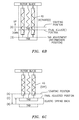
- FIGS. 6A-6C is a schematic block diagram representation of a trim tab position change.
- FIG. 1 schematically illustrates an exemplary main rotor blade 10 mounted to a rotor hub assembly (not shown) for rotation about an axis of rotation A.
- the main rotor blade 10 includes an inboard section 12 , an intermediate section 14 , and an outboard section 16 .
- the inboard, intermediate, and outboard sections 12 , 14 , 16 define a blade radius R between an axis of rotation A and a blade tip 18 .
- the main rotor blade 10 has a leading edge 20 and a trailing edge 22 , which define the chord C of the main rotor blade 10 .
- Adjustable trim tabs 24 extend rearwardly from the trailing edge 22 .
- upper and lower skins 26 , 28 define the upper and lower aerodynamic surfaces of the main rotor blade 10 .
- a honeycomb core 30 , a spar 32 , one or more counterweights 33 , and a leading-edge sheath 34 typically form the interior support for the skins 26 , 28 of the main rotor blade 10 .
- relative positional terms such as “forward,” “aft,” “upper,” “lower,” “above,” “below,” and the like are with reference to the normal operational attitude of the vehicle and should not be considered otherwise limiting.
- the trim tab assembly 24 generally includes an upper and lower doubler 34 , 36 a first and second shape memory alloy (SMA) actuator 38 , 40 and a trim tab substrate 42 between the SMA actuators 38 , 40 .
- SMA shape memory alloy
- SMA as utilized herein may include one of several induced strain actuation mechanisms such as elastic/plastic locking, piereteramic, magnetostrictive, general SMA, bi-directional SMA, induced strain actuation mechanisms that require a zero-power or power-off locking mechanism, and other induced strain actuation concepts.
- the SMA actuators 38 , 40 may be manufactured from temperature-dependent martensitic-to-austenitic phase transformation materials that transition from a low-symmetry to a high symmetry crystallographic structure in response to heating (resistive or other) such as a copper-zinc-aluminum, copper-aluminum-nickel, and nickel-titanium (NiTi) alloys.
- the trim tab substrate 42 may be manufactured of a metal such as aluminum or a composite material which exhibits elastic/plastic stress/strain characteristics, for example, a composite with a metallic layer to generally define the aerodynamic portion of the tab assembly 24 .
- the trim tab assembly 24 is positioned in response to a controller 44 which drives a power source 46 to selectively activate either or both of the first SMA actuators 38 and the second SMA actuators 40 .
- first and second SMA actuators 38 , 40 are directly adjacent each other to form the trim tab assembly 24 A without the intermediate trim tab substrate 42 ( FIG. 3B ).
- first and second SMA actuators 38 , 40 are located within the intermediate trim tab substrate 42 ( FIG. 3C ) to form the trim tab assembly 24 B.
- various materials may be utilized to form the trim tab substrate 42 as the trim tab substrate 42 may be utilized to facilitate positioning of the trim tab assembly 24 ( FIG. 3B ) and may alternatively or additionally encase the SMA actuators 38 , 40 therein ( FIG. 3C ).
- appropriate materials may be utilized therefor—typically aluminum for intermediate material and a flexible composite for encasement material.
- first SMA actuators 38 and the second SMA actuators 40 inter-digitated along the length of the trim tab assembly 24 ( FIG. 3D ) to form the trim tab assembly 24 .
- Inter-digitation provides opportunities for redundancy, fine tuning and uniform versus multi-spanwise deformation which facilitated inter-digitation operation in which only a subset of the trim tab assembly 24 are operated.
- the first SMA actuator 38 When activated, the first SMA actuator 38 generally flexes the trim tab assembly 24 in an upward direction relative the blade trailing edge 22 ( FIGS. 4A , 4 B). Conversely, the second SMA actuator 40 generally flexes the trim tab assembly 24 in a downward direction when activated ( FIGS. 4A , 4 C). It should be understood that the first SMA actuator 38 and the second SMA actuator 40 may be unidirectional or bidirectional in operation.
- the unactivated SMA actuators are flexed through an elastic deformation range and into a plastic deformation range to lock the trim tab assembly 24 in the desired position.
- the trim tab substrate 42 alternatively or additionally facilitates retention of the trim tab assembly 24 in the flexed position.
- the first SMA actuator 38 or the second SMA actuator 40 is activated to position the non-activated first SMA actuator 38 , or second SMA actuator 40 as well as the trim tab substrate 42 . That is, either the opposing SMA actuators 38 , 40 and/or the substrate 42 may undergo plastic deformation.
- the trim tab assembly 24 is flexed through elastic strain and into plastic strain ( FIG. 5A ) such that the trim tab assembly 24 is positioned to the desired position after some elastic spring back ( FIG. 5B ). That is, the trim tab assembly 24 may be flexed past the desired final position by appropriate activation of the SMA actuators 38 , 40 to account for elastic spring back to the desired final position.
- the active SMA element the passive SMA element and the passive substrate.
- the SMA effect in the active SMA element generates an induced strain or actuation strain. This actuation strain tends to deform the active SMA element and is resisted by the passive SMA and substrate. The end result is an equilibrium deformation wherein the SMA actuation is balanced by the passive SMA element and the passive substrate which are thereby plastically deformed.
- the input to the first SMA actuator 38 and the second SMA actuator 40 are provided by the controller 44 to achieve the desired final position. It should be understood that various final positions relative various starting positions are determined by the controller 44 . It should also be understood that although the first SMA actuators 38 are illustrated as being activated to flex the trim tab assembly 24 in an upward direction, and the second SMA actuators 40 are activated to flex the trim tab assembly 24 in a downward direction, this is for simplified descriptive purposes only and the reverse as well as other activation schemes, both full and proportional may likewise be utilized herewith. Desired trim tab assembly 24 position may be achieved during flight or on the ground.
- the trim tab assembly 24 is schematically illustrated for operational example.
- the second SMA actuators 40 are actuated to adjust the trim tab assembly 24 to a downwardly flexed position.
- the second SMA actuators 40 When the second SMA actuators 40 are activated ( FIG. 6B ), the second SMA actuators 40 flex the first SMA actuators 38 and the trim tab substrate 42 (if utilized in the particular embodiment) past the desired final adjusted position to an intermediate portion.
- the second SMA actuators 40 may remain actuated for a period of time then turned-off to permit the trim tab assembly 24 to spring back to the final adjusted position. That is, non-activated SMA actuator 38 and the trim tab substrate 42 (if utilized in the particular embodiment) will spring-back to some extent to achieve the desired final adjusted position.
- the intermediate portion and the time at the intermediate portion to achieve the desired final adjusted position are achieved by the controller 44 .
- power need not be provided once the new final adjusted position is achieved.
- helicopter configuration is illustrated and described in the disclosed embodiment, other configurations and/or machines, such as high speed compound rotary wing aircraft with supplemental translational thrust systems, dual contra-rotating, coaxial rotor system aircraft, turbo-props, tilt-rotors and tilt-wing aircraft, will also benefit from the present invention.
Abstract
Description
Claims (20)
Priority Applications (3)
| Application Number | Priority Date | Filing Date | Title |
|---|---|---|---|
| US11/962,257 US8043053B2 (en) | 2007-12-21 | 2007-12-21 | Self locking trim tab |
| PCT/US2008/078064 WO2009085352A1 (en) | 2007-12-21 | 2008-09-29 | Self locking trim tab |
| EP08867527.7A EP2234882B1 (en) | 2007-12-21 | 2008-09-29 | Self locking trim tab |
Applications Claiming Priority (1)
| Application Number | Priority Date | Filing Date | Title |
|---|---|---|---|
| US11/962,257 US8043053B2 (en) | 2007-12-21 | 2007-12-21 | Self locking trim tab |
Publications (2)
| Publication Number | Publication Date |
|---|---|
| US20090162199A1 US20090162199A1 (en) | 2009-06-25 |
| US8043053B2 true US8043053B2 (en) | 2011-10-25 |
Family
ID=40788855
Family Applications (1)
| Application Number | Title | Priority Date | Filing Date |
|---|---|---|---|
| US11/962,257 Expired - Fee Related US8043053B2 (en) | 2007-12-21 | 2007-12-21 | Self locking trim tab |
Country Status (3)
| Country | Link |
|---|---|
| US (1) | US8043053B2 (en) |
| EP (1) | EP2234882B1 (en) |
| WO (1) | WO2009085352A1 (en) |
Cited By (4)
| Publication number | Priority date | Publication date | Assignee | Title |
|---|---|---|---|---|
| US9440737B1 (en) * | 2012-05-11 | 2016-09-13 | The Boeing Company | Apparatus to adjust airfoils of rotor blades |
| US20170341743A1 (en) * | 2015-04-24 | 2017-11-30 | Sikorsky Aircraft Corporation | Trim tab retention system, an aircraft employing same and a method of retaining a trim tab within a blade housing |
| US11155322B2 (en) | 2018-10-01 | 2021-10-26 | Marine Canada Acquisition Inc. | Watertight electric actuator for trim tab assembly or wake gate assembly |
| US11396815B1 (en) * | 2021-07-21 | 2022-07-26 | The Boeing Company | Structure for trailing edge portion of rotor blade and method of manufacturing the structure |
Families Citing this family (9)
| Publication number | Priority date | Publication date | Assignee | Title |
|---|---|---|---|---|
| DE102007030095B4 (en) * | 2007-06-28 | 2012-12-20 | Eurocopter Deutschland Gmbh | Rotor blade for a rotary wing aircraft |
| EP2450764B1 (en) | 2010-11-05 | 2016-05-11 | Sikorsky Aircraft Corporation | Implementation of Kalman filter linear state estimator for actuator equalization |
| KR101275846B1 (en) * | 2010-11-30 | 2013-06-17 | 부산대학교 산학협력단 | Rotor blade with protruding trailing edge |
| CN103587684B (en) * | 2013-10-24 | 2016-03-02 | 中国科学院长春光学精密机械与物理研究所 | Dimensional airfoil under a kind of low reynolds number and adopt the rotor of this aerofoil profile |
| US9776705B2 (en) * | 2014-07-29 | 2017-10-03 | The Boeing Company | Shape memory alloy actuator system for composite aircraft structures |
| US10626846B2 (en) * | 2016-11-17 | 2020-04-21 | General Electric Company | System for wind turbine blade actuation |
| TR202011723A1 (en) | 2020-07-23 | 2022-02-21 | Tusaş Türk Havacilik Ve Uzay Sanayi̇i̇ Anoni̇m Şi̇rketi̇ | An actuation mechanism. |
| CN112550663B (en) * | 2020-12-08 | 2022-11-11 | 中国空气动力研究与发展中心设备设计及测试技术研究所 | Deformable wing based on intelligent driving device |
| CN113232833B (en) * | 2021-05-14 | 2022-03-25 | 南京航空航天大学 | Shape memory alloy stay wire driven variable camber wing and design method thereof |
Citations (15)
| Publication number | Priority date | Publication date | Assignee | Title |
|---|---|---|---|---|
| US4461611A (en) | 1982-05-20 | 1984-07-24 | United Technologies Corporation | Helicopter rotor with blade trailing edge tabs responsive to control system loading |
| US4806077A (en) | 1986-07-28 | 1989-02-21 | Societe Nationale Industrielle Et Aerospatiale | Composite material blade with twin longeron and twin box structure having laminated honeycomb sandwich coverings and a method of manufacturing same |
| US5111676A (en) | 1990-10-04 | 1992-05-12 | United Technologies Corporation | Tool for selectively bending the trailing edge tab of a helicopter blade while simultaneously measuring the true degree of tab bending |
| US5492448A (en) | 1993-03-13 | 1996-02-20 | Westland Helicopters Limited | Rotary blades |
| US6322324B1 (en) | 2000-03-03 | 2001-11-27 | The Boeing Company | Helicopter in-flight rotor tracking system, method, and smart actuator therefor |
| US6644081B1 (en) | 2002-02-15 | 2003-11-11 | Joseph Keith Berry | System and method for adjusting helicopter blade trim tabs |
| US20040056751A1 (en) * | 2002-09-18 | 2004-03-25 | Byong-Ho Park | Tubular compliant mechanisms for ultrasonic imaging systems and intravascular interventional devices |
| US20040261411A1 (en) * | 1999-08-12 | 2004-12-30 | Macgregor Roderick | Shape-memory alloy actuators and control methods |
| US20050150223A1 (en) * | 2000-03-03 | 2005-07-14 | United Technologies Corporation | Shape memory alloy bundles and actuators |
| US6940186B2 (en) | 2002-05-02 | 2005-09-06 | General Electric Company | Wind turbine having sensor elements mounted on rotor blades |
| US6942455B2 (en) | 2003-06-12 | 2005-09-13 | Sikorsky Aircraft Corporation | Strain isolated trim tab |
| US7083383B2 (en) | 2004-04-26 | 2006-08-01 | The Boeing Company | Segmented rotor blade trim tab |
| US7143711B1 (en) | 2005-04-07 | 2006-12-05 | Wolske James P Von | Trim tab shape control system |
| US20070016062A1 (en) * | 2005-05-04 | 2007-01-18 | Byong-Ho Park | Multiple transducers for intravascular ultrasound imaging |
| US7165746B2 (en) | 2001-06-07 | 2007-01-23 | Sagem Sa | Vibration motor primary flight control actuator |
Family Cites Families (13)
| Publication number | Priority date | Publication date | Assignee | Title |
|---|---|---|---|---|
| US3169875A (en) * | 1962-12-04 | 1965-02-16 | North Carolina State College O | Process for producing a dehydrated pumpkin product |
| US3597231A (en) * | 1968-01-02 | 1971-08-03 | Frederic J Kane | Dehydrated pumpkin mix |
| US4526799A (en) * | 1982-03-08 | 1985-07-02 | General Foods Corporation | Process for preparing a high quality, reduced-calorie cake |
| US4503083A (en) * | 1982-03-08 | 1985-03-05 | General Foods Corporation | High quality, reduced-calorie cake |
| US5234706A (en) * | 1986-01-31 | 1993-08-10 | Slimak K M | Processes for products from potatoes and other roots, seeds, and fruit |
| US5000974A (en) * | 1986-11-12 | 1991-03-19 | International Flavors & Fragrances, Inc. | Process of the preparation of fruit, vegetable or spicy aerated foods |
| US5260087A (en) * | 1992-07-28 | 1993-11-09 | Charles Stad | Fat and egg yolk substitute for use in baking and process for using substitute |
| US6235334B1 (en) * | 1992-10-13 | 2001-05-22 | Margaret Elizabeth Donovan | No fat, no cholesterol cake and process of making the same |
| US5422132A (en) * | 1993-08-12 | 1995-06-06 | Caden; Jeffrey A. | Low fat food product |
| US5752672A (en) * | 1996-05-29 | 1998-05-19 | Continuum Dynamics, Inc. | Remotely controllable actuating device |
| US5688548A (en) * | 1996-08-15 | 1997-11-18 | The J. M. Smucker Company | Non-fat baking ingredient and method of making |
| US6220550B1 (en) * | 1998-03-31 | 2001-04-24 | Continuum Dynamics, Inc. | Actuating device with multiple stable positions |
| US6284303B1 (en) * | 1998-12-10 | 2001-09-04 | Bestfoods | Vegetable based creamy food and process therefor |
-
2007
- 2007-12-21 US US11/962,257 patent/US8043053B2/en not_active Expired - Fee Related
-
2008
- 2008-09-29 WO PCT/US2008/078064 patent/WO2009085352A1/en active Application Filing
- 2008-09-29 EP EP08867527.7A patent/EP2234882B1/en active Active
Patent Citations (16)
| Publication number | Priority date | Publication date | Assignee | Title |
|---|---|---|---|---|
| US4461611A (en) | 1982-05-20 | 1984-07-24 | United Technologies Corporation | Helicopter rotor with blade trailing edge tabs responsive to control system loading |
| US4806077A (en) | 1986-07-28 | 1989-02-21 | Societe Nationale Industrielle Et Aerospatiale | Composite material blade with twin longeron and twin box structure having laminated honeycomb sandwich coverings and a method of manufacturing same |
| US5111676A (en) | 1990-10-04 | 1992-05-12 | United Technologies Corporation | Tool for selectively bending the trailing edge tab of a helicopter blade while simultaneously measuring the true degree of tab bending |
| US5492448A (en) | 1993-03-13 | 1996-02-20 | Westland Helicopters Limited | Rotary blades |
| US20040261411A1 (en) * | 1999-08-12 | 2004-12-30 | Macgregor Roderick | Shape-memory alloy actuators and control methods |
| US6322324B1 (en) | 2000-03-03 | 2001-11-27 | The Boeing Company | Helicopter in-flight rotor tracking system, method, and smart actuator therefor |
| US6453669B2 (en) | 2000-03-03 | 2002-09-24 | The Boeing Company | Helicopter in-flight rotor tracking system, method, and smart actuator therefor |
| US20050150223A1 (en) * | 2000-03-03 | 2005-07-14 | United Technologies Corporation | Shape memory alloy bundles and actuators |
| US7165746B2 (en) | 2001-06-07 | 2007-01-23 | Sagem Sa | Vibration motor primary flight control actuator |
| US6644081B1 (en) | 2002-02-15 | 2003-11-11 | Joseph Keith Berry | System and method for adjusting helicopter blade trim tabs |
| US6940186B2 (en) | 2002-05-02 | 2005-09-06 | General Electric Company | Wind turbine having sensor elements mounted on rotor blades |
| US20040056751A1 (en) * | 2002-09-18 | 2004-03-25 | Byong-Ho Park | Tubular compliant mechanisms for ultrasonic imaging systems and intravascular interventional devices |
| US6942455B2 (en) | 2003-06-12 | 2005-09-13 | Sikorsky Aircraft Corporation | Strain isolated trim tab |
| US7083383B2 (en) | 2004-04-26 | 2006-08-01 | The Boeing Company | Segmented rotor blade trim tab |
| US7143711B1 (en) | 2005-04-07 | 2006-12-05 | Wolske James P Von | Trim tab shape control system |
| US20070016062A1 (en) * | 2005-05-04 | 2007-01-18 | Byong-Ho Park | Multiple transducers for intravascular ultrasound imaging |
Non-Patent Citations (1)
| Title |
|---|
| Search Report for International Application No. PCT/US2008/078064 dated May 22, 2009. |
Cited By (5)
| Publication number | Priority date | Publication date | Assignee | Title |
|---|---|---|---|---|
| US9440737B1 (en) * | 2012-05-11 | 2016-09-13 | The Boeing Company | Apparatus to adjust airfoils of rotor blades |
| US20170341743A1 (en) * | 2015-04-24 | 2017-11-30 | Sikorsky Aircraft Corporation | Trim tab retention system, an aircraft employing same and a method of retaining a trim tab within a blade housing |
| US10589849B2 (en) * | 2015-04-24 | 2020-03-17 | Sikorsky Aircraft Corporation | Trim tab retention system, an aircraft employing same and a method of retaining a trim tab within a blade housing |
| US11155322B2 (en) | 2018-10-01 | 2021-10-26 | Marine Canada Acquisition Inc. | Watertight electric actuator for trim tab assembly or wake gate assembly |
| US11396815B1 (en) * | 2021-07-21 | 2022-07-26 | The Boeing Company | Structure for trailing edge portion of rotor blade and method of manufacturing the structure |
Also Published As
| Publication number | Publication date |
|---|---|
| WO2009085352A1 (en) | 2009-07-09 |
| EP2234882B1 (en) | 2019-09-04 |
| EP2234882A4 (en) | 2013-08-28 |
| US20090162199A1 (en) | 2009-06-25 |
| EP2234882A1 (en) | 2010-10-06 |
Similar Documents
| Publication | Publication Date | Title |
|---|---|---|
| US8043053B2 (en) | Self locking trim tab | |
| Straub | A feasibility study of using smart materials for rotor control | |
| US10507907B2 (en) | Vortex generators responsive to ambient conditions | |
| US10272987B2 (en) | Autonomous slat-cove-filler device for reduction of aeroacoustic noise associated with aircraft systems | |
| EP2562080B1 (en) | Variable camber fluid-dynamic body utilizing optimized smart materials | |
| US6345792B2 (en) | Actuating device with at least three stable positions | |
| US8882049B2 (en) | Airfoil system for cruising flight | |
| CA2772297C (en) | Active gurney flap | |
| Kudva et al. | Overview of the DARPA/AFRL/NASA smart wing phase II program | |
| EP2316732B1 (en) | Active rotor blade control effector system for a rotary-wing aircraft | |
| CN105980701A (en) | Means for alleviating strain on a wind turbine rotor blade | |
| US20130064666A1 (en) | Active twist hollow beam system | |
| CA2982999C (en) | Enhanced performance rotorcraft rotor blade | |
| US20110064579A1 (en) | Active Twist Hollow Beam System | |
| US20110236208A1 (en) | Rotary wing blade, a rotary wing including such a blade, and an aircraft | |
| JP2013227015A (en) | Shape memory alloy actuation system for flight control surface | |
| EP2514667B1 (en) | Active gurney flap | |
| US6984109B2 (en) | Rotor blade pitch control assembly | |
| JP2020500120A (en) | Operable aircraft components | |
| JP6577207B2 (en) | Aero car deformable wing and method of deforming the wing | |
| EP3988446B1 (en) | Flow control device | |
| EP2535269B1 (en) | Rotor blade with active flap | |
| Miller et al. | The application of helicopter rotor blade active control systems for noise and vibration reduction and performance improvement | |
| Simpson et al. | Application of electromechanical technologies to enhance adaptive aircraft structures |
Legal Events
| Date | Code | Title | Description |
|---|---|---|---|
| AS | Assignment |
Owner name: SIKORSKY AIRCRAFT CORPORATION,CONNECTICUT Free format text: ASSIGNMENT OF ASSIGNORS INTEREST;ASSIGNOR:BERNHARD, ANDREAS;REEL/FRAME:020782/0921 Effective date: 20080131 Owner name: SIKORSKY AIRCRAFT CORPORATION, CONNECTICUT Free format text: ASSIGNMENT OF ASSIGNORS INTEREST;ASSIGNOR:BERNHARD, ANDREAS;REEL/FRAME:020782/0921 Effective date: 20080131 |
|
| ZAAA | Notice of allowance and fees due |
Free format text: ORIGINAL CODE: NOA |
|
| ZAAB | Notice of allowance mailed |
Free format text: ORIGINAL CODE: MN/=. |
|
| STCF | Information on status: patent grant |
Free format text: PATENTED CASE |
|
| FPAY | Fee payment |
Year of fee payment: 4 |
|
| MAFP | Maintenance fee payment |
Free format text: PAYMENT OF MAINTENANCE FEE, 8TH YEAR, LARGE ENTITY (ORIGINAL EVENT CODE: M1552); ENTITY STATUS OF PATENT OWNER: LARGE ENTITY Year of fee payment: 8 |
|
| FEPP | Fee payment procedure |
Free format text: MAINTENANCE FEE REMINDER MAILED (ORIGINAL EVENT CODE: REM.); ENTITY STATUS OF PATENT OWNER: LARGE ENTITY |
|
| LAPS | Lapse for failure to pay maintenance fees |
Free format text: PATENT EXPIRED FOR FAILURE TO PAY MAINTENANCE FEES (ORIGINAL EVENT CODE: EXP.); ENTITY STATUS OF PATENT OWNER: LARGE ENTITY |
|
| STCH | Information on status: patent discontinuation |
Free format text: PATENT EXPIRED DUE TO NONPAYMENT OF MAINTENANCE FEES UNDER 37 CFR 1.362 |
|
| FP | Lapsed due to failure to pay maintenance fee |
Effective date: 20231025 |