US7993096B2 - Wind turbine with adjustable airfoils - Google Patents
Wind turbine with adjustable airfoils Download PDFInfo
- Publication number
- US7993096B2 US7993096B2 US12/509,236 US50923609A US7993096B2 US 7993096 B2 US7993096 B2 US 7993096B2 US 50923609 A US50923609 A US 50923609A US 7993096 B2 US7993096 B2 US 7993096B2
- Authority
- US
- United States
- Prior art keywords
- airfoils
- hub
- carousel
- trailing edge
- adjustment mechanism
- Prior art date
- Legal status (The legal status is an assumption and is not a legal conclusion. Google has not performed a legal analysis and makes no representation as to the accuracy of the status listed.)
- Expired - Fee Related, expires
Links
- 230000007246 mechanism Effects 0.000 claims abstract description 60
- 230000033001 locomotion Effects 0.000 claims abstract description 16
- 238000003306 harvesting Methods 0.000 claims abstract description 7
- 238000006073 displacement reaction Methods 0.000 claims 1
- 238000000926 separation method Methods 0.000 abstract description 4
- 230000009467 reduction Effects 0.000 description 3
- 238000005057 refrigeration Methods 0.000 description 3
- 230000007423 decrease Effects 0.000 description 2
- 239000012530 fluid Substances 0.000 description 2
- 239000011888 foil Substances 0.000 description 2
- 230000005428 wave function Effects 0.000 description 2
- 238000013459 approach Methods 0.000 description 1
- 230000002939 deleterious effect Effects 0.000 description 1
- 238000010586 diagram Methods 0.000 description 1
- 230000026058 directional locomotion Effects 0.000 description 1
- 230000000694 effects Effects 0.000 description 1
- 238000000605 extraction Methods 0.000 description 1
- 230000005484 gravity Effects 0.000 description 1
- 230000000977 initiatory effect Effects 0.000 description 1
- 238000003780 insertion Methods 0.000 description 1
- 230000037431 insertion Effects 0.000 description 1
- 238000009434 installation Methods 0.000 description 1
- 238000012423 maintenance Methods 0.000 description 1
- 238000000034 method Methods 0.000 description 1
- 230000004048 modification Effects 0.000 description 1
- 238000012986 modification Methods 0.000 description 1
- 230000008569 process Effects 0.000 description 1
- 230000001681 protective effect Effects 0.000 description 1
- 230000008439 repair process Effects 0.000 description 1
- 230000000717 retained effect Effects 0.000 description 1
- 125000006850 spacer group Chemical group 0.000 description 1
- 230000004083 survival effect Effects 0.000 description 1
- XLYOFNOQVPJJNP-UHFFFAOYSA-N water Substances O XLYOFNOQVPJJNP-UHFFFAOYSA-N 0.000 description 1
Images


Classifications
-
- F—MECHANICAL ENGINEERING; LIGHTING; HEATING; WEAPONS; BLASTING
- F03—MACHINES OR ENGINES FOR LIQUIDS; WIND, SPRING, OR WEIGHT MOTORS; PRODUCING MECHANICAL POWER OR A REACTIVE PROPULSIVE THRUST, NOT OTHERWISE PROVIDED FOR
- F03D—WIND MOTORS
- F03D3/00—Wind motors with rotation axis substantially perpendicular to the air flow entering the rotor
- F03D3/06—Rotors
- F03D3/062—Rotors characterised by their construction elements
- F03D3/066—Rotors characterised by their construction elements the wind engaging parts being movable relative to the rotor
- F03D3/067—Cyclic movements
- F03D3/068—Cyclic movements mechanically controlled by the rotor structure
-
- F—MECHANICAL ENGINEERING; LIGHTING; HEATING; WEAPONS; BLASTING
- F03—MACHINES OR ENGINES FOR LIQUIDS; WIND, SPRING, OR WEIGHT MOTORS; PRODUCING MECHANICAL POWER OR A REACTIVE PROPULSIVE THRUST, NOT OTHERWISE PROVIDED FOR
- F03D—WIND MOTORS
- F03D7/00—Controlling wind motors
- F03D7/06—Controlling wind motors the wind motors having rotation axis substantially perpendicular to the air flow entering the rotor
-
- F—MECHANICAL ENGINEERING; LIGHTING; HEATING; WEAPONS; BLASTING
- F05—INDEXING SCHEMES RELATING TO ENGINES OR PUMPS IN VARIOUS SUBCLASSES OF CLASSES F01-F04
- F05B—INDEXING SCHEME RELATING TO WIND, SPRING, WEIGHT, INERTIA OR LIKE MOTORS, TO MACHINES OR ENGINES FOR LIQUIDS COVERED BY SUBCLASSES F03B, F03D AND F03G
- F05B2260/00—Function
- F05B2260/50—Kinematic linkage, i.e. transmission of position
-
- F—MECHANICAL ENGINEERING; LIGHTING; HEATING; WEAPONS; BLASTING
- F05—INDEXING SCHEMES RELATING TO ENGINES OR PUMPS IN VARIOUS SUBCLASSES OF CLASSES F01-F04
- F05B—INDEXING SCHEME RELATING TO WIND, SPRING, WEIGHT, INERTIA OR LIKE MOTORS, TO MACHINES OR ENGINES FOR LIQUIDS COVERED BY SUBCLASSES F03B, F03D AND F03G
- F05B2260/00—Function
- F05B2260/70—Adjusting of angle of incidence or attack of rotating blades
- F05B2260/72—Adjusting of angle of incidence or attack of rotating blades by turning around an axis parallel to the rotor centre line
-
- Y—GENERAL TAGGING OF NEW TECHNOLOGICAL DEVELOPMENTS; GENERAL TAGGING OF CROSS-SECTIONAL TECHNOLOGIES SPANNING OVER SEVERAL SECTIONS OF THE IPC; TECHNICAL SUBJECTS COVERED BY FORMER USPC CROSS-REFERENCE ART COLLECTIONS [XRACs] AND DIGESTS
- Y02—TECHNOLOGIES OR APPLICATIONS FOR MITIGATION OR ADAPTATION AGAINST CLIMATE CHANGE
- Y02E—REDUCTION OF GREENHOUSE GAS [GHG] EMISSIONS, RELATED TO ENERGY GENERATION, TRANSMISSION OR DISTRIBUTION
- Y02E10/00—Energy generation through renewable energy sources
- Y02E10/70—Wind energy
- Y02E10/74—Wind turbines with rotation axis perpendicular to the wind direction
Definitions
- the present invention relates generally to wind powered energy generating devices and in particular to wind power generating devices of the vertical axis airfoil type.
- VAWT's vertical axis wind turbines
- HAWT's horizontal axis wind turbines
- a HAWT is desirably mounted on a high tower to lift it and the blades thereof above air obstructions that create turbulent or obstructed wind flow that hinder its performance.
- a HAWT is also generally limited to two or three propellers which travel at high tip speed, well above the incident wind speed.
- the rotating shaft typically couples a generator to a gear box, both mounted to the tower and hence difficult to install and service.
- the propeller blades often use variable pitch to more efficiently harvest a major part of all the energy in the wind over the entire disk aperture swept by the blades As a result thereof, HAWT's can require powered assistance to initiate rotation once a minimal wind speed is sensed.
- VAWT's can have many individual blades allowing for operation in low wind speeds and do not have to be “facing” into the wind as initiation of rotation can occur from any wind direction. This ability to work immediately from any wind direction and in low wind speeds makes VAWT's more ideally suited for smaller low ground installations. A VAWT then obviates the cost of a high tower and reduces the difficulty of access to various turbine components for replacement or repair. VAWT's therefore hold out the possibility of providing a lower cost wind power alternative and for areas where an HAWT would not be suitable due to lower than required average wind speeds.
- VAWT's of the Savonius type the blades only produce power during half of their rotation and fight against the wind during the return half thereof.
- VAWT's can not rotate at a speed greater than the wind speed thereby severely limiting their ability to harvest power from the available wind.
- a Darrieus or “eggbeater” type VAWT's are known that produce power in both directions, but suffer from the fact that they often need assistance to get their rotation started.
- a third type of VAWT sometimes referred to as a Gyromill, uses airfoils rotating around a vertical axis that also provide power through each full rotation. Frequently the vanes are designed to provide adequate torque to provide for self start-up at zero rotational velocity, but due to their inherent large amount of drag are limited in the peak attainable velocity. In some designs airfoil orientation can be maximized for start-up and then adjusted for high speed running. It is also known to cycle or vary the angle of attack as the vane moves from the “upwind” to the “downwind” part of the rotational path to improve wind energy harvest performance. However, a major problem therewith concerns the cost, complexity, increased maintenance and reduction of generation efficiency that result from the mechanisms that exist to provide for such airfoil adjustment.
- VAWT that can maximize the ability to harvest wind power through airfoil adjustment and do so with a mechanism that is simple, reliable and low in cost.
- the present invention is of the VAWT type and provides for a simplified and compact yet robust mechanism for adjusting airfoil orientation and for doing so during the operation thereof.
- the invention herein includes a plurality of vertically extending symmetrical airfoils having a wider leading edge tapering to a thin trailing edge.
- Each airfoil is pivotally secured near its leading edge on a bottom end thereof to spoke arms extending from a lower central hub.
- the top ends thereof are also pivotally secured at the same leading edge point to the ends of upper spoke arms extending from an upper central hub.
- a central vertically extending drive shaft is secured to the bottom and top hubs of the upper and lower spoke arms forming a rotating airfoil carousel.
- a lower end of the central drive shaft provides for connection to a driven device, such as, an electrical generator, refrigeration compressor, fluid pump, and the like as well as to a base support structure.
- a plurality of airfoil trailing edge spokes are pivotally secured to the top ends of each of the airfoils near the trailing edges thereof.
- the opposite ends of the trailing edge spokes are secured to a trailing edge angle adjusting hub.
- the trailing edge hub overlies the upper spoke arm hub wherein an airfoil angle adjusting mechanism is pivotally positioned there between.
- the airfoil angle adjusting mechanism includes an electrically operated screw mechanism for rotating a threaded shaft for positioning a threaded carrier there along.
- An adjustment shaft is secured to the carrier and extends upwardly there from and centrally through the trailing edge pitch angle control central hub.
- a wind vane or rudder is secured to the adjustment shaft.
- the central axis of the trailing edge angle adjusting hub coextends with the axis of both the collinear upper and lower leading edge hubs and both rotate about that same axis.
- the invention herein is designed so that at this zero position the linear extension of the airfoils is parallel with lines tangent to the circle of rotation defined thereby. This designates a pitch angle of zero of the airfoils. Operation of the screw motor moves the pitch angle control hub and its associated trailing edge spokes relative to the upper leading edge spoke arms whereby the central axes thereof are separated by a distance D. This movement results in movement of the trailing edges of the airfoils by a pitch angle gamma relative to that zero position tangent line.
- the resultant pitch angle gamma has a maximum or gamma max ( ⁇ MAX ) that is equal to the arcsine of D/C.
- the adjustment mechanism is held relatively motionless by virtue of its pivotal mounting and by connection to the rudder which is held in position by the wind direction at the particular time.
- the trailing edge hub and spoke structure is substantially rigid, airfoils positioned 180 degrees apart, that is, on opposite sides from each other, will have the opposite gamma angle.
- the airfoils will have a positive gamma and on a second half thereof the airfoils will have a negative gamma.
- An angle theta is used to describe the 360 degrees of arc of one rotation of the airfoil carousel with a theta angle of zero degrees being the point there around facing directly into the wind.
- An airfoil at the zero theta position has a maximum gamma angle as does an airfoil position at a theta of 180 degrees however at a negative value of that gamma angle.
- the rudder will move accordingly thereby moving the adjustment mechanism and the trailing edge adjustment hub relative to the airfoil carousel. This movement serves to insure that the zero degree theta position is constantly directly facing the wind.
- any one airfoil can be seen to describe a cosine wave function wherein gamma decreases from a maximum gamma angle at zero degrees theta to a zero gamma at 90 degrees, then to a negative gamma maximum at a theta of 180 degrees whereupon it then moves to a zero gamma at 270 degrees followed by a return to the maximum gamma as that airfoil completes one rotation back to a theta of zero.
- the screw motor can be understood to regulate the distance D between the centers of the trailing edge adjustment hub and the carousel and thereby regulate the size of the angle gamma. That ability is critical for obtaining maximum performance of the wind turbine of the present invention. At start-up those of skill will understand that a large positive gamma is desirable to create an amount of aerodynamic drag whereby sufficient torque can be exerted against the airfoils to initiate rotation, particularly in a low wind condition. Once sufficient rotational speed is achieved, the angle gamma can be reduced to reduce drag and permit increased rotational speed.
- An electronic control mechanism is connected to the screw motor and adjusts the angle gamma as a function of the wind speed and rotational speed of the carousel.
- power for the electronic control and/or the screw motor is provided by solar cells having a rechargeable battery reserve.
- the adjustment mechanism being housed between the trailing edge adjustment hub and the upper carousel or leading edge hub serves to protect those components from the deleterious effects of weather. Additionally, that approach combined with the particular connection of the rudder to the adjustment shaft provides for a vertically compact mechanism and also one that is robust and durable.
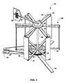
- FIG. 1 shows a perspective view of the present invention.
- FIG. 2 shows a top plan view of the present invention.
- FIG. 3 shows an enlarged view of an airfoil top end.
- FIG. 4 shows an enlarged cross-sectional view of the upper central hub and the trailing edge cable central hub.
- FIG. 5 shows a diagrammatic top plan view of the airfoils of the present invention having a zero axis offset.
- FIG. 6 shows a diagrammatic top plan view of the airfoils of the present invention having a positive axis offset.
- FIG. 7 shows a diagrammatic top plan view of the airfoils of the present invention having a negative gamma setting.
- FIG. 8 shows a diagrammatic top plan view of the airfoils of the present invention in a safety stop mode.
- FIG. 9 shows a top plan cross-sectional view of a preferred category of airfoil.
- FIG. 10 shows a top plan cross-sectional view of a further category of airfoil.
- FIG. 11 shows a top plan cross-sectional view of a further category of airfoil.
- FIG. 12 shows a schematic diagram of the electronic control of the present invention.
- FIG. 13 shows a perspective view of an alternative embodiment of the present invention.
- FIG. 14 show a perspective cut away view of the embodiment of FIG. 11 having the upper housing removed.
- FIG. 15 shows an enlarged cross-sectional view of the embodiment shown in FIG. 13 .
- Turbine 10 includes a plurality of vertically extending airfoils 12 each having a leading edge 14 and a trailing edge 16 .
- Each airfoil 12 is pivotally secured at its leading edge 14 on a bottom end thereof to spoke arms 18 extending from a lower central hub 20 .
- the top ends of airfoils 12 are also pivotally secured at top ends thereof to the same point there along at the leading edge 14 to the ends of upper spoke arms 22 extending from an upper central hub 24 .
- FIG. 10 includes a plurality of vertically extending airfoils 12 each having a leading edge 14 and a trailing edge 16 .
- Each airfoil 12 is pivotally secured at its leading edge 14 on a bottom end thereof to spoke arms 18 extending from a lower central hub 20 .
- the top ends of airfoils 12 are also pivotally secured at top ends thereof to the same point there along at the leading edge 14 to the ends of upper spoke arms 22 extending from an upper central hub 24 .
- each arm spoke 22 includes a hole 23 for insertion therein of a pin 25 extending from its corresponding airfoil 12 to provide for the stated pivotal connection there between.
- a spring return mechanism includes a spring 27 extending around pin 25 and retained on one end thereof in a hole 27 a of arm 22 and a hole 27 b of airfoil 12 .
- a central vertically extending drive shaft 26 is secured to bottom and top hubs 20 and 24 respectively forming a rotating airfoil carousel 28 .
- a lower end of drive shaft 26 provides for connection by a belt and pulley system to a driven device 30 , such as, an electrical generator, refrigeration compressor, fluid pump, and the like as well as to a base support structure 32 .
- driven device 30 could also be directly connected to shaft 26 where an armature or working shaft thereof co-rotates there with.
- a plurality of airfoil trailing edge pitch angle adjustment spoke arms 34 are pivotally secured to pins 35 extending from the top ends of each of the airfoils 12 near trailing edges 16 thereof. Referring again to FIG. 3 , a chord length C is defined by the distance between pins 25 and 35 along bisecting line BL. The opposite ends of trailing edge spoke arms 34 are secured to a trailing edge pitch angle adjusting central hub 36 . Trailing edge pitch angle adjusting hub 36 overlies upper spoke arm hub 24 wherein a screw adjustment mechanism 37 is pivotally positioned there between.
- angle adjusting hub 36 serves to define an interior housing area 36 a in which screw adjustment mechanism 37 is located.
- Mechanism 37 is positioned on a plate 38 which is positioned pivotally on and above a spacer hub 39 .
- Hub 39 is secured to upper shaft hub 24 and rotates there with.
- Adjustment mechanism 37 includes an electrically operated drive motor 40 secured to plate 38 for rotating a threaded shaft 41 for positioning a threaded nut carrier 42 there along.
- An upwardly extending shaft 43 defines a central axis of angle adjusting housing 36 and is secured to carrier 42 .
- a rudder 44 is secured to a rudder arm 45 which is, in turn, is secured to upwardly extending shaft 43 .
- An electronic control 46 is used to regulate the operation of adjustment mechanism 37 and is powered by a rechargeable battery 47 .
- Battery 47 is secured to plate 38 and is charged by photovoltaic solar cells 48 positioned on rudder 44 and connected thereto by wires 49 .
- Wires 49 extend from cells 47 to battery 46 through a shaft 50 extending through rudder arm 44 .
- Control 45 is secured to motor 40 communicates wirelessly with a sensor system 52 which provide information as to carousel rotational speed and load demand.
- An anemometer not shown, provides information as to wind speed wirelessly to control 46 .
- adjustment mechanism 37 When adjustment mechanism 37 is at a position zero the central axis defined around adjustment shaft 43 of trailing edge pitch angle adjustment hub 36 coextends with the axis of shaft 26 of both the collinear upper and lower leading edge arm hubs 24 and 20 respectively wherein both rotate about that same axis.
- the invention herein is designed so that at this zero position the pitch angle of the airfoils is zero wherein the linear extension thereof 12 is parallel with lines L 1 tangent to the circle of rotation defined thereby.
- This movement of trailing edges 16 can be defined by a pitch angle gamma, indicated as ⁇ , relative to lines L 1 tangent to circle C 1 .
- the largest or maximum angle gamma ( ⁇ MAX ) is defined by the existing axial separation distance D.
- adjustment mechanism 37 can provide for a wide range of angles gamma and preferably from a positive gamma angle of 90 degrees to a negative gamma angle of approximately 6 degrees.
- ⁇ MAX the nomenclature in FIG. 6 refers to the maximum gamma angle achievable relative to a particularly selected offset distance D, as opposed to the largest value of gamma achievable by adjustment mechanism 37 .
- Airfoils 12 rotate through an angle theta ( ⁇ ) of 360 degrees for each revolution of carousel 28 .
- ⁇ theta
- theta is seen in FIG. 6 and is defined as the point on circle C 1 that intersects with the diameter thereof and faces directly into the wind, which wind direction is defined by arrow W.
- adjustment mechanism 37 is held relatively motionless by virtue of its pivotal mounting between hubs 36 and 24 and by connection to rudder 43 which is held in position by the wind direction at the particular time. As the wind direction changes rudder 43 will move accordingly thereby moving the adjustment mechanism 37 and the trailing edge angle adjustment hub 36 relative to carousel 28 . This movement serves to insure that the zero degree theta position is constantly directly facing the wind. Therefore, as an airfoil 12 moves from an angle theta of zero through to a theta angle of 90 degrees, the gamma angle thereof reduces from the gamma max value to zero.
- the eccentric positioning of the central axis of trailing edge hub 36 causes the airfoils to swing back and forth between a positive gamma angle and a negative gamma angle.
- the movement of a trailing edge 14 of any one airfoil 12 can be seen to describe a cosine wave function wherein gamma decreases from gamma max at zero degrees theta to a gamma of zero at 90 degrees, then to a negative gamma max at a theta of 180 degrees whereupon it then moves to a zero gamma at 270 degrees followed by a return to a positive gamma max as that airfoil completes one rotation back to a theta of zero.
- adjustment mechanism 37 has changed the relative positions of axes 26 and 43 , indicated as a ⁇ D therein, in order to provide for a negative angle gamma at the theta equals zero position.
- a small negative gamma was found to be of values in certain higher wind speed situations.
- a gamma angle approaching 90 degrees is shown.
- a pitch angle gamma of somewhat less than 90 degrees is desirable to insure that trailing edge spokes 34 are easily and reliably returned to a smaller gamma angle, i.e. do not go over 90 degrees and result in airfoils 12 rotating in an opposite or undesired direction resulting in interference with spokes 22 .
- the maximum pitch angle gamma resulting from a particular distance of separation D of the axes of shafts 26 and 43 is a function thereof as well as of the chord length C, seen in FIG. 3 . Specifically, the maximum pitch angle gamma is equal to the arcsine of D/C.
- airfoils 12 have a length of four feet and a bisecting line (BL) length of 6 inches and a chord length C of 4 inches.
- Adjustment device 37 has the capacity to set the distance to from the zero point thereof to a positive 3 inches D and to a slight negative distance D.
- the negative distance D provides for setting a negative gamma angle of up to approximately 6 degrees as referred to in the discussion above relative to FIG. 7 .
- leading edge pins 25 are typically at a point slightly ahead of the center of gravity or airfoils 12 . This provides for suitable g-loading of the trailing edges 16 thereof under rotation to insure the desired outward directional movement thereof.
- leading edge pins 25 can be placed approximately one fourth of the distance from leading edge 14 along line BL.
- Trailing edge pins 35 can also be placed approximately one fourth of the distance from trailing edge 16 along line BL.
- leading and trailing edge spokes 22 and 34 respectively can consist of rods, cables, channels stock and the like sufficient to effect the positioning and movement of airfoils 12 . Where cables are used the g-loading is particularly useful to maintain a taut condition thereof.
- Spring mechanism 27 serve to maintain pressure serving to also provide for correct positioning the trailing edges 16 of airfoils 12 .
- FIGS. 9 , 10 and 11 various airfoil geometries are shown and are illustrative of skill of some of the major classifications thereof.
- the preferred embodiment 60 is seen in FIG. 9 and referred to as a symmetric airfoil.
- a symmetrical airfoil such as NACA0018, provides for good lift and a relatively reduced stall region.
- a flat foil 70 is seen in FIG. 11 and could be used though not as efficiently as airfoil 60 .
- Arcuate foil 80 can work well but is more costly to produce and can present more drag.
- electronic control mechanism 46 receives inputs from sensor 52 which includes a carousel rotation sensor 90 and a load sensor 92 , Control 46 also receives data from a wind speed sensor 94 , such as an anemometer. Preferably, this data is provided to control 46 wirelessly. Control 46 therefore regulates the offset distance D by operation of adjustment mechanism 37 , and hence, the value of the angle gamma. Adjustment mechanism 37 can comprise a screw motor and it and control 46 are powered by battery 47 . Battery 47 is preferably charged by solar cells 48 . Control 46 and sensor 52 both serve to operate a carousel braking mechanism 96 to slow or stop carousel 28 .
- control 46 can appropriately regulate the offset D and hence the angle gamma.
- control 46 will signal for a relatively large gamma angle, generally on the order of 45 degrees. A large gamma angle will be understood to create sufficient lift to initiate rotation.
- control 46 will signal adjustment mechanism to reduce offset D and thus the gamma angle. It will be appreciated that while a large gamma produces lift In order to initiate rotation, it is done at the expense of a proportionally large amount of aerodynamic drag. This drag will limit the maximum achievable carousel rotational speed for a given wind speed, thus reduction of the angle gamma will reduce drag and permit faster rotation and larger wind energy harvest.
- control 46 can reduce speed by placing a load on driven device 30 and/or by increasing the gamma angle to increase drag and slow rotation. If those strategies are not sufficient to maintain rotation speed below a designed safety limit, brake mechanism 96 can be engaged by either control 46 or sensor 52 for as a redundant precaution.
- a further strategy for wind speed reduction, and particularly in very high wind speeds where survival of the turbine structure is the goal, as opposed to any energy extraction, is to set airfoils 12 to a gamma angle of nearly 90 degrees as previously shown in FIG. 8 .
- airfoils 12 will be essentially parallel with the wind and provide no lift, and hence, little or no rotation.
- Wind turbine 100 works in essentially the same manner as previously described turbine 10 and generally has the same arrangement of parts.
- turbine 100 includes a protective housing 102 that defines an interior area 103 and includes a plurality of feet 104 that are attached to angle adjustment rods 106 .
- Rods 106 are pivotally secured to trailing edge ends of airfoils 108 .
- Airfoils 108 are pivotally secured on their top and bottom leading edge ends to upper spokes 110 and lower spokes 112 .
- Upper and lower spokes 110 and 112 emanate there from and are integral with their respective spoke hubs 114 and 116 respectively.
- Hubs 114 and 116 are secured to a central shaft 120 which is connected to a driven device 122 , such as, an electric generator, refrigeration compressor, water pump, air pump or the like.
- Airfoil retaining wires 126 are secured to shaft 120 and to airfoils 108 to provide for additional structural strength due to stresses encountered thereby as the result of the centrifugal forces experienced by airfoils 108 during rotation thereof.
- a base 128 and base support wires 130 provide for support of driven device 122 and turbine 100 to an above ground position to avoid low level turbulence and as a safety precaution to prevent human or animal interference with the rotational movement of turbine 100 .
- a horizontal support plate 128 is pivotally mounted on shaft 120 so that shaft 120 rotates independently thereof and is positioned within space 103 .
- Plate 128 supports thereon an angle adjustment screw motor device 129 .
- Adjustment device 129 includes a drive motor, 130 , a driven threaded screw 132 and a threaded carrier 134 .
- Carrier 134 includes a shaft 136 extending vertically through a central opening of housing 102 and secured to a rudder arm 138 .
- Arm 138 is secured to a rudder 140 and includes a conduit shaft 142 through which wires 144 extend from photovoltaic solar cell array 48 to battery 47 .
- Control 46 and battery 47 are also supported on plate 128 .
- a secondary housing 146 serves to protect adjustment mechanism 129 , control 46 and battery 47 .
- Wind turbine 100 works in substantially the same manner as previously described herein for Turbine 10 .
- adjustment mechanism 129 is operated by control 46 to set an appropriate axial separation distance D between the axis of rotation defined by central shaft 120 and that defined by carrier shaft 136 .
- the difference between the two embodiments concerns the structure of housing or hub 102 providing a strategy or structure for providing a relatively increased interior area for retaining and protecting adjustment mechanism 129 and its associated control 46 and battery 47 .
- embodiment 100 as well as embodiment 10 are shown as rotating about a vertical axis but that rotation about a horizontal axis or, in fact, a plurality of axes extending about an arc of 360 degrees is possible.
Abstract
Description
Claims (12)
Priority Applications (1)
| Application Number | Priority Date | Filing Date | Title |
|---|---|---|---|
| US12/509,236 US7993096B2 (en) | 2009-07-24 | 2009-07-24 | Wind turbine with adjustable airfoils |
Applications Claiming Priority (1)
| Application Number | Priority Date | Filing Date | Title |
|---|---|---|---|
| US12/509,236 US7993096B2 (en) | 2009-07-24 | 2009-07-24 | Wind turbine with adjustable airfoils |
Publications (2)
| Publication Number | Publication Date |
|---|---|
| US20110020123A1 US20110020123A1 (en) | 2011-01-27 |
| US7993096B2 true US7993096B2 (en) | 2011-08-09 |
Family
ID=43497462
Family Applications (1)
| Application Number | Title | Priority Date | Filing Date |
|---|---|---|---|
| US12/509,236 Expired - Fee Related US7993096B2 (en) | 2009-07-24 | 2009-07-24 | Wind turbine with adjustable airfoils |
Country Status (1)
| Country | Link |
|---|---|
| US (1) | US7993096B2 (en) |
Cited By (6)
| Publication number | Priority date | Publication date | Assignee | Title |
|---|---|---|---|---|
| US20130127173A1 (en) * | 2011-11-17 | 2013-05-23 | Doosan Heavy Industries & Construction Co., Ltd. | Multi-type wind turbine |
| US20150016997A1 (en) * | 2013-07-15 | 2015-01-15 | Young-Sil Yu | Wind turbine rotor having vertical blades |
| US20150192105A1 (en) * | 2014-01-09 | 2015-07-09 | Hing Kwok Dennis Chu | Rotors for extracting energy from wind and hydrokinetic sources |
| TWI561730B (en) * | 2016-05-18 | 2016-12-11 | Inst Nuclear Energy Res Atomic Energy Council | Vertical-axis wind turbine having device for changing blade angle |
| US20180030956A1 (en) * | 2015-02-05 | 2018-02-01 | Vijay Rao | Fluid Turbine with Control System |
| US10927810B2 (en) * | 2019-03-26 | 2021-02-23 | Imam Abdulrahman Bin Faisal University | Real time pitch actuation in a vertical axis wind turbine |
Families Citing this family (18)
| Publication number | Priority date | Publication date | Assignee | Title |
|---|---|---|---|---|
| US8584475B2 (en) * | 2009-06-30 | 2013-11-19 | George Scesney | Self-contained water generation system |
| US8482247B2 (en) * | 2010-04-23 | 2013-07-09 | General Electric Company | Package foil for protecting wind turbine components from the environment, method for packaging a wind turbine component, and wind turbine component assembly |
| EP2577052A2 (en) * | 2010-05-28 | 2013-04-10 | Airborne Energy Limited | Vertical axis wind turbine |
| ITFI20110071A1 (en) * | 2011-04-14 | 2012-10-15 | Abdullah Amirian | REVERSIBLE HYDRAULIC DEVICE FOR ENERGY CONVERSION. |
| CA2835398C (en) * | 2011-07-07 | 2016-12-13 | 7142871 Canada Inc. | Horizontal multiple stages wind turbine |
| JP6035543B2 (en) * | 2011-08-22 | 2016-11-30 | 上野 康男 | Windmill power unit |
| US9447690B2 (en) | 2011-09-15 | 2016-09-20 | 3 Phase Energy Systems, Inc. | Wind generator hub assembly with hybrid sail blades |
| FR2997736A1 (en) * | 2012-11-02 | 2014-05-09 | Pascal Epineau | Vertical axis wind mill e.g. Darrieus wind mill, has blades diametrically opposite relative to rotor axis and connected together by connection unit, where unit is extended, so that pivoting of one of blades causes pivoting of another blade |
| GB201305221D0 (en) * | 2013-03-21 | 2013-05-01 | Swift Tg Energy Scotland Ltd | A turbine, turbine controller and method of operation thereof |
| ITUA20163710A1 (en) * | 2016-05-04 | 2017-11-04 | Flaminio Fracaroli | WIND TURBINE WITH VERTICAL AXIS WITH MOBILE BLADES |
| KR101691933B1 (en) * | 2016-05-24 | 2017-01-02 | 유원기 | Tidal Current Generator |
| US10788016B2 (en) | 2017-05-10 | 2020-09-29 | Gerald L. Barber | Transitioning wind turbine |
| CN110799747A (en) * | 2017-05-10 | 2020-02-14 | 杰拉尔德·巴伯 | Segmented airfoil design for cable routing |
| GB2561926B (en) * | 2017-07-04 | 2020-04-29 | Vertogen Ltd | Wind turbine |
| CN108547734B (en) * | 2018-04-19 | 2019-10-15 | 安徽六和同心风能设备有限公司 | A kind of automatic speed-limiting vertical axis aerogenerator |
| CN108374754A (en) * | 2018-05-09 | 2018-08-07 | 杭州辚萧科技有限公司 | A kind of vertical axis wind energy generator adjustable wing system |
| US10844836B2 (en) * | 2018-08-17 | 2020-11-24 | Carlos Nielbock | Wind turbine generator |
| US10920751B2 (en) * | 2018-12-12 | 2021-02-16 | Ziaur Rahman | Orthogonal turbine having a speed adjusting member |
Citations (7)
| Publication number | Priority date | Publication date | Assignee | Title |
|---|---|---|---|---|
| US4278894A (en) * | 1977-12-16 | 1981-07-14 | Gelindo Ciman | Wind-driven power generator |
| US4302684A (en) | 1979-07-05 | 1981-11-24 | Gogins Laird B | Free wing turbine |
| US4832569A (en) | 1986-04-11 | 1989-05-23 | Eirik Samuelsen | Governed vane wind turbine |
| US5676524A (en) * | 1995-03-08 | 1997-10-14 | Lukas; Peter | Vertical-axis wind turbine |
| US6320273B1 (en) * | 2000-02-12 | 2001-11-20 | Otilio Nemec | Large vertical-axis variable-pitch wind turbine |
| US7040858B2 (en) * | 2001-12-14 | 2006-05-09 | Global Energy Co., Ltd | Wind power generator, windmill, and spindle and blade of the windmill |
| US20090136346A1 (en) * | 2007-11-23 | 2009-05-28 | Samuel Thomas Kelly | Vertical axis wind turbine |
-
2009
- 2009-07-24 US US12/509,236 patent/US7993096B2/en not_active Expired - Fee Related
Patent Citations (7)
| Publication number | Priority date | Publication date | Assignee | Title |
|---|---|---|---|---|
| US4278894A (en) * | 1977-12-16 | 1981-07-14 | Gelindo Ciman | Wind-driven power generator |
| US4302684A (en) | 1979-07-05 | 1981-11-24 | Gogins Laird B | Free wing turbine |
| US4832569A (en) | 1986-04-11 | 1989-05-23 | Eirik Samuelsen | Governed vane wind turbine |
| US5676524A (en) * | 1995-03-08 | 1997-10-14 | Lukas; Peter | Vertical-axis wind turbine |
| US6320273B1 (en) * | 2000-02-12 | 2001-11-20 | Otilio Nemec | Large vertical-axis variable-pitch wind turbine |
| US7040858B2 (en) * | 2001-12-14 | 2006-05-09 | Global Energy Co., Ltd | Wind power generator, windmill, and spindle and blade of the windmill |
| US20090136346A1 (en) * | 2007-11-23 | 2009-05-28 | Samuel Thomas Kelly | Vertical axis wind turbine |
Cited By (11)
| Publication number | Priority date | Publication date | Assignee | Title |
|---|---|---|---|---|
| US20130127173A1 (en) * | 2011-11-17 | 2013-05-23 | Doosan Heavy Industries & Construction Co., Ltd. | Multi-type wind turbine |
| US9013053B2 (en) * | 2011-11-17 | 2015-04-21 | Doosan Heavy Industries & Construction Co., Ltd. | Multi-type wind turbine |
| US20150016997A1 (en) * | 2013-07-15 | 2015-01-15 | Young-Sil Yu | Wind turbine rotor having vertical blades |
| US20150192105A1 (en) * | 2014-01-09 | 2015-07-09 | Hing Kwok Dennis Chu | Rotors for extracting energy from wind and hydrokinetic sources |
| US20180030956A1 (en) * | 2015-02-05 | 2018-02-01 | Vijay Rao | Fluid Turbine with Control System |
| TWI561730B (en) * | 2016-05-18 | 2016-12-11 | Inst Nuclear Energy Res Atomic Energy Council | Vertical-axis wind turbine having device for changing blade angle |
| US10927810B2 (en) * | 2019-03-26 | 2021-02-23 | Imam Abdulrahman Bin Faisal University | Real time pitch actuation in a vertical axis wind turbine |
| US11236725B2 (en) | 2019-03-26 | 2022-02-01 | Imam Abdulrahman Bin Faisal University | Wind power generation device with real time pitch actuation |
| US11486354B2 (en) | 2019-03-26 | 2022-11-01 | Imam Abdulrahman Bin Faisal University | Vertical axis wind turbine |
| US11603820B2 (en) | 2019-03-26 | 2023-03-14 | Imam Abdulrahman Bin Faisal University | Wind turbine power generation system |
| US11644008B1 (en) | 2019-03-26 | 2023-05-09 | Imam Abdulrahman Bin Faisal University | Vertical axis wind turbine having vertical rotor apparatus |
Also Published As
| Publication number | Publication date |
|---|---|
| US20110020123A1 (en) | 2011-01-27 |
Similar Documents
| Publication | Publication Date | Title |
|---|---|---|
| US7993096B2 (en) | Wind turbine with adjustable airfoils | |
| EP1861619B1 (en) | Tension wheel in a rotor system for wind and water turbines | |
| US7008171B1 (en) | Modified Savonius rotor | |
| US4832569A (en) | Governed vane wind turbine | |
| US8668433B2 (en) | Multi-turbine airflow amplifying generator | |
| US10612515B2 (en) | Vertical axis wind turbine | |
| US9041239B2 (en) | Vertical axis wind turbine with cambered airfoil blades | |
| US5599168A (en) | Wind turbine adaptable to wind direction and velocity | |
| EP2344757A2 (en) | Cable-stayed rotor for wind and water turbines | |
| US11236724B2 (en) | Vertical axis wind turbine | |
| US20130017084A1 (en) | High efficiency verical axis wind turbine | |
| EP3564525B1 (en) | Vertical shaft wind power generator driving device for self-adaptive variable-propeller, and wind power generator | |
| US7766602B1 (en) | Windmill with pivoting blades | |
| EP2697507A1 (en) | Device and system for harvesting the energy of a fluid stream | |
| WO2014106049A1 (en) | Power generation apparatus | |
| AU2008222708B2 (en) | Hubless windmill | |
| CN201943888U (en) | Wind sail type generator | |
| US20120061972A1 (en) | Vertical-axis wind turbine | |
| KR20120139154A (en) | Vertical axis type wind power generator fused lift and drag | |
| GB2476830A (en) | Vertical axis wind powered generator | |
| CN209892383U (en) | Wind wheel device of wind driven generator with tiltable blades | |
| KR20120115196A (en) | Wind power generator with vertical rotor | |
| CN112969849A (en) | High efficiency wind energy converter without gearbox or multipole generator | |
| JP2002081364A (en) | Wind force device | |
| US20120049536A1 (en) | Wind Turbine |
Legal Events
| Date | Code | Title | Description |
|---|---|---|---|
| AS | Assignment |
Owner name: HEID, TOM, MINNESOTA Free format text: ASSIGNMENT OF ASSIGNORS INTEREST;ASSIGNOR:WINFIN, INC.;REEL/FRAME:025188/0627 Effective date: 20101015 |
|
| AS | Assignment |
Owner name: WINFIN, INC., MINNESOTA Free format text: ASSIGNMENT OF ASSIGNORS INTEREST;ASSIGNORS:ANDERSON, DONALD E, MR.;CHRISTIAN, DANIEL, MR.;REEL/FRAME:025816/0830 Effective date: 20110214 |
|
| STCF | Information on status: patent grant |
Free format text: PATENTED CASE |
|
| FPAY | Fee payment |
Year of fee payment: 4 |
|
| FEPP | Fee payment procedure |
Free format text: MAINTENANCE FEE REMINDER MAILED (ORIGINAL EVENT CODE: REM.); ENTITY STATUS OF PATENT OWNER: SMALL ENTITY |
|
| FEPP | Fee payment procedure |
Free format text: 7.5 YR SURCHARGE - LATE PMT W/IN 6 MO, SMALL ENTITY (ORIGINAL EVENT CODE: M2555); ENTITY STATUS OF PATENT OWNER: SMALL ENTITY |
|
| MAFP | Maintenance fee payment |
Free format text: PAYMENT OF MAINTENANCE FEE, 8TH YR, SMALL ENTITY (ORIGINAL EVENT CODE: M2552); ENTITY STATUS OF PATENT OWNER: SMALL ENTITY Year of fee payment: 8 |
|
| FEPP | Fee payment procedure |
Free format text: MAINTENANCE FEE REMINDER MAILED (ORIGINAL EVENT CODE: REM.); ENTITY STATUS OF PATENT OWNER: SMALL ENTITY |
|
| LAPS | Lapse for failure to pay maintenance fees |
Free format text: PATENT EXPIRED FOR FAILURE TO PAY MAINTENANCE FEES (ORIGINAL EVENT CODE: EXP.); ENTITY STATUS OF PATENT OWNER: SMALL ENTITY |
|
| STCH | Information on status: patent discontinuation |
Free format text: PATENT EXPIRED DUE TO NONPAYMENT OF MAINTENANCE FEES UNDER 37 CFR 1.362 |
|
| FP | Lapsed due to failure to pay maintenance fee |
Effective date: 20230809 |