US7804184B2 - System and method for control of a grid connected power generating system - Google Patents
System and method for control of a grid connected power generating system Download PDFInfo
- Publication number
- US7804184B2 US7804184B2 US12/358,327 US35832709A US7804184B2 US 7804184 B2 US7804184 B2 US 7804184B2 US 35832709 A US35832709 A US 35832709A US 7804184 B2 US7804184 B2 US 7804184B2
- Authority
- US
- United States
- Prior art keywords
- converter
- controller
- power
- voltage
- current
- Prior art date
- Legal status (The legal status is an assumption and is not a legal conclusion. Google has not performed a legal analysis and makes no representation as to the accuracy of the status listed.)
- Active
Links
- 238000000034 method Methods 0.000 title claims description 13
- 241000555745 Sciuridae Species 0.000 claims description 2
- 230000006698 induction Effects 0.000 claims description 2
- 230000000903 blocking effect Effects 0.000 claims 1
- 230000010354 integration Effects 0.000 claims 1
- 238000010586 diagram Methods 0.000 description 11
- 238000001514 detection method Methods 0.000 description 4
- 230000001360 synchronised effect Effects 0.000 description 4
- 230000009466 transformation Effects 0.000 description 4
- 239000011159 matrix material Substances 0.000 description 3
- 230000035515 penetration Effects 0.000 description 3
- 230000008901 benefit Effects 0.000 description 2
- 239000000446 fuel Substances 0.000 description 2
- 230000004048 modification Effects 0.000 description 2
- 238000012986 modification Methods 0.000 description 2
- 230000001052 transient effect Effects 0.000 description 2
- 230000002411 adverse Effects 0.000 description 1
- 230000033228 biological regulation Effects 0.000 description 1
- 230000008859 change Effects 0.000 description 1
- 230000003247 decreasing effect Effects 0.000 description 1
- 230000001419 dependent effect Effects 0.000 description 1
- 230000004044 response Effects 0.000 description 1
- 230000002441 reversible effect Effects 0.000 description 1
- 230000001960 triggered effect Effects 0.000 description 1
Images


Classifications
-
- H—ELECTRICITY
- H02—GENERATION; CONVERSION OR DISTRIBUTION OF ELECTRIC POWER
- H02J—CIRCUIT ARRANGEMENTS OR SYSTEMS FOR SUPPLYING OR DISTRIBUTING ELECTRIC POWER; SYSTEMS FOR STORING ELECTRIC ENERGY
- H02J3/00—Circuit arrangements for ac mains or ac distribution networks
- H02J3/38—Arrangements for parallely feeding a single network by two or more generators, converters or transformers
- H02J3/381—Dispersed generators
-
- H—ELECTRICITY
- H02—GENERATION; CONVERSION OR DISTRIBUTION OF ELECTRIC POWER
- H02J—CIRCUIT ARRANGEMENTS OR SYSTEMS FOR SUPPLYING OR DISTRIBUTING ELECTRIC POWER; SYSTEMS FOR STORING ELECTRIC ENERGY
- H02J3/00—Circuit arrangements for ac mains or ac distribution networks
- H02J3/38—Arrangements for parallely feeding a single network by two or more generators, converters or transformers
- H02J3/46—Controlling of the sharing of output between the generators, converters, or transformers
-
- H—ELECTRICITY
- H02—GENERATION; CONVERSION OR DISTRIBUTION OF ELECTRIC POWER
- H02J—CIRCUIT ARRANGEMENTS OR SYSTEMS FOR SUPPLYING OR DISTRIBUTING ELECTRIC POWER; SYSTEMS FOR STORING ELECTRIC ENERGY
- H02J2300/00—Systems for supplying or distributing electric power characterised by decentralized, dispersed, or local generation
- H02J2300/20—The dispersed energy generation being of renewable origin
- H02J2300/28—The renewable source being wind energy
-
- Y—GENERAL TAGGING OF NEW TECHNOLOGICAL DEVELOPMENTS; GENERAL TAGGING OF CROSS-SECTIONAL TECHNOLOGIES SPANNING OVER SEVERAL SECTIONS OF THE IPC; TECHNICAL SUBJECTS COVERED BY FORMER USPC CROSS-REFERENCE ART COLLECTIONS [XRACs] AND DIGESTS
- Y02—TECHNOLOGIES OR APPLICATIONS FOR MITIGATION OR ADAPTATION AGAINST CLIMATE CHANGE
- Y02E—REDUCTION OF GREENHOUSE GAS [GHG] EMISSIONS, RELATED TO ENERGY GENERATION, TRANSMISSION OR DISTRIBUTION
- Y02E10/00—Energy generation through renewable energy sources
- Y02E10/70—Wind energy
- Y02E10/72—Wind turbines with rotation axis in wind direction
-
- Y—GENERAL TAGGING OF NEW TECHNOLOGICAL DEVELOPMENTS; GENERAL TAGGING OF CROSS-SECTIONAL TECHNOLOGIES SPANNING OVER SEVERAL SECTIONS OF THE IPC; TECHNICAL SUBJECTS COVERED BY FORMER USPC CROSS-REFERENCE ART COLLECTIONS [XRACs] AND DIGESTS
- Y02—TECHNOLOGIES OR APPLICATIONS FOR MITIGATION OR ADAPTATION AGAINST CLIMATE CHANGE
- Y02E—REDUCTION OF GREENHOUSE GAS [GHG] EMISSIONS, RELATED TO ENERGY GENERATION, TRANSMISSION OR DISTRIBUTION
- Y02E10/00—Energy generation through renewable energy sources
- Y02E10/70—Wind energy
- Y02E10/76—Power conversion electric or electronic aspects
Definitions
- the present invention relates generally to power generating systems connected to a grid and, more particularly, to control of power generating systems during weak grid operation.
- Wind turbine generators are regarded as environmentally friendly and relatively inexpensive alternative sources of energy that utilize wind energy to produce electrical power.
- Wind turbines can be distinguished in two types: fixed speed and variable speed turbines.
- the variable speed wind turbines are controlled as current sources connected to a power grid.
- the variable speed wind turbines rely on a grid frequency detected by a phase locked loop (PLL) as a reference and inject a specified amount of current into the grid.
- PLL phase locked loop
- the conventional current source control of the wind turbines is based on the assumptions that the grid voltage waveforms are fundamental voltage waveforms with fixed frequency and magnitude and that the penetration of wind power into the grid is low enough so as to not result in disturbances. Thus, the wind turbines simply inject the specified current into the grid based on the fundamental voltage waveforms. However, with the rapid growth of the wind power, wind power penetration into some grids has increased to the point where wind turbine generators have a significant impact on the grid voltage and frequency.
- a power generating system in accordance with one exemplary embodiment of the present invention, includes a wind turbine and a converter to couple the wind turbine to a power grid.
- the system further includes a first controller for calculating voltage commands to emulate a phasor back electromotive force behind an inductance.
- the controller further generates converter switching commands based on the voltage commands.
- the voltage commands include a voltage magnitude reference, an internal frequency reference calculated from a power imbalance between an active power reference and the electrical power.
- the system also includes a second controller to limit a converter current.
- a solar power generating system in accordance with another exemplary embodiment, includes a photovoltaic cell and a converter to couple the photovoltaic cell to a power grid.
- the system further includes a first controller for calculating voltage commands to emulate a phasor back electromotive force behind an inductance.
- the controller further generates converter switching commands based on the voltage commands.
- the voltage commands include a voltage magnitude reference, an internal frequency reference calculated from a power imbalance between a mechanical power reference and the electrical power.
- the system also includes a second controller to limit a converter current magnitude.
- a method for supplying electrical power to a power grid includes generating the electrical power from an electrical source and controlling the electrical source to emulate a phasor back electromotive force behind an inductance.
- the method further includes limiting a converter current magnitude.
- controlling the electrical source includes calculating voltage commands and using the voltage commands for generating converter switching commands, wherein the voltage commands include a voltage magnitude reference, an internal frequency reference calculated from an imbalance between a mechanical power reference and the electrical power.
- FIG. 1 is a diagrammatical representation of a conventional current source controlled wind power generating system connected to a power grid;
- FIG. 2 is a diagrammatical representation of a control system of the wind power generating system of FIG. 1 ;
- FIG. 3 is a diagrammatical representation of a voltage source controlled wind power generating system, in accordance with an embodiment of the present invention
- FIG. 4 is a diagrammatical representation of a wind turbine converter control of the wind power generating system of FIG. 3 ;
- FIG. 5 is a diagrammatical representation of a detailed control system for a grid side converter, in accordance with an embodiment of the present invention.
- FIG. 6 is diagrammatical representation of a control system with a current limiter of the wind power generating system of FIG. 3 ;
- FIG. 7 is a diagrammatical representation of a instantaneous current limiter, in accordance with an embodiment of the present invention.
- FIG. 8 is a phasor diagram representing an implementation of a phasor current limiter in accordance with an embodiment of the present invention.
- FIG. 9 is a diagrammatical representation of another power generating system embodiment wherein the control system of present invention is implemented.
- embodiments of the present invention function to provide methods and systems to control grid connected power generating systems. It provides a voltage source controlled wind power generating system. Although the present discussion focuses on wind power generating system, the present invention is applicable to any power generating system with a controllable or uncontrollable input energy source and a power electronic converter interface.
- FIG. 1 shows a conventional grid connected wind power generating system 10 with current source control.
- the system includes a wind generator 12 , a generator side converter 14 and a grid side converter 16 .
- the system further includes a grid side controller 18 , a generator side controller 20 and a power grid 22 .
- the power grid 22 typically includes traditional synchronous generators 24 and electrical loads 26 .
- a direct current (DC) link 28 connects the generator side converter 14 and the grid side converter 16 .
- the generator side converter 14 converts alternating current (AC) power generated by the wind generator 12 into DC power.
- the grid side converter 18 then converts the DC power to AC power at a frequency compatible with the power grid 22 .
- the combination of the grid side controller 18 and grid side converter 16 functions as a current source for the grid 22 .
- the grid side controller 18 controls the phase and amplitude of the output current 30 of grid side converter 16 .
- the grid side controller includes a phase locked loop (PLL) 32 , a DC voltage regulator 34 , a current regulator 36 and a reactive power regulator 40 .
- the PLL 32 senses three phase voltages of the power grid and generates a frequency and phase reference for the grid side converter 16 .
- the DC voltage regulator 34 helps in maintaining the DC link voltage at a desired value, and the reactive power regulator 40 helps in supplying desired amount of reactive power into the grid.
- the current regulator 36 generates the output current reference for the grid side converter 16 based on the PLL output, the DC voltage regulator output, and the reactive power regulator output.
- the generator side controller 20 generates switching signals for the generator side converter 14 .
- a turbine controller 38 provides a torque reference to the generator side controller 20 based on wind velocity or rotor speed of the wind turbine. The turbine controller generates the torque reference such that maximum energy is captured from the wind.
- the current source control of the wind power generating system 10 of FIG. 1 maintains the output current of the wind turbine 42 based on the frequency and phase of the grid voltage detected by PLL.
- the output current will have significant impact on the grid voltage.
- the PLL is generating the output current reference based on the grid voltage and as the grid voltage is dependent on the output current itself, stability problems may occur. Stability issues may also occur because of the limited bandwidth of current source control.
- the current source control responds slowly to high frequency voltage distortions. Thus, in a current source control wind power generating system the output currents cannot always follow the grid voltage distortions due to grid network resonance conditions.
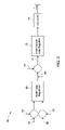
- FIG. 2 shows a grid side converter control block diagram 60 of the wind power generating system of FIG. 1 .
- a reference DC link voltage command 62 an actual DC voltage feedback 64 , a reference reactive power command 66 , and an actual reactive power feedback 67 are inputs to an output closed loop regulator 68 .
- the outer closed loop control regulator 68 generates the reference current commands 69 .
- a current feedback 70 is subtracted from the reference current commands 69 and then the error signals 71 are provided to an inner current loop regulator 72 .
- the inner current loop regulator 72 provides switching signals to the grid side converter 74 .
- the frequency and the phase reference for the current source are generated by the PLL 30 ( FIG. 1 ).
- the grid side converter 74 injects the current into the grid.
- FIG. 3 shows a grid connected wind power generating system 90 with voltage source control in accordance with one embodiment of the present invention.
- the wind power generating system 90 includes the wind generator 12 , the generator side converter 14 , and the grid side converter 16 .
- the system further includes the grid side controller 18 , the generator side controller 20 and the power grid 22 .
- the wind generator 12 comprises a squirrel cage induction generator.
- the wind generator 12 may comprise a synchronous generator or a permanent magnet synchronous generator.
- the generator side controller 20 generates the switching signals for the generator side converter 14 .
- the generator side controller helps in maintaining the DC link voltage to a desired value.
- the grid side converter 16 is controlled as a voltage source connected to the grid 22 .
- the grid side controller 18 controls the phase and amplitude of the output voltage of grid side converter directly.
- the grid side converter when controlled as the voltage source, responds to grid changes as a voltage behind a reactance.
- the wind generator 12 operates in a similar manner as a synchronous generator.
- the grid side controller of the embodiment of FIG. 3 receives the power reference from the turbine controller 38 .
- An internal frequency reference is generated based on the power imbalance between the reference power and the actual electrical power supplied to the grid.
- a power/frequency (P/F) regulator (not shown) may be used to share the power with other wind turbines, i.e., for paralleling operation of wind turbines.
- the power frequency regulator determines the phase angle reference for the grid side controller 18 .
- FIG. 4 shows a grid side converter control block diagram 100 of the wind power generating system of FIG. 3 , in accordance with one embodiment of the present invention.
- a reference active power command 102 and a reference reactive power command 104 are inputs to an outer closed loop controller 110 .
- a measured active power feedback 106 and a measured reactive power feedback 108 are also fed back to the outer closed loop regulator 110 .
- the outer closed loop control regulator 110 generates the voltage commands 112 for a voltage source 114 , and voltage commands 112 include both the magnitude command and frequency/phase command.
- the voltage source 114 may include a second controller (not shown) to limit the converter current and the grid side converter 16 of FIG. 3 .
- the voltage source 114 generates the output voltage and feeds the active power into the grid.
- FIG. 5 shows a detailed control system 130 for the grid side converter, in accordance with an embodiment of the present invention.
- the turbine controller 38 generates an active or mechanical power reference 102 or a mechanical power reference or a torque reference for the control system 130 .
- An internal frequency reference 132 is generated based on the difference between or imbalance between the actual electrical power supplied to the grid 134 and the reference mechanical power 102 . It should be noted here that the internal frequency reference 132 is different than the grid frequency.
- a reference phase angle 136 for the control system 130 is generated by integrating the frequency reference 132 . It should also be noted here that the PLL 32 is not used to generate the frequency reference or the phase reference.
- the PLL 32 is used only for protection purposes and ensures that the reference phase angle does not differ too much from the actual measured PLL angle.
- a farm controller 138 generates the reactive power reference 104 for the control system 130
- a reactive power regulator 110 generates voltage reference 140 for the control system 130 .
- the grid side converter is controlled as a voltage source or controlled to emulate a back-electromotive force (EMF) behind an inductance.
- EMF is controlled by the voltage magnitude reference 140 and the internal frequency reference 132 .
- control system 132 also includes an abc-xy transformation matrix 142 for voltage transformation.
- the transformation matrix 142 converts 3-phase stationary quantities into 2-phase rotating quantities.
- the reverse transformation xy-abc matrix 144 converts the 2-phase rotating voltage coordinates into 3-phase stationary voltage coordinates.
- the voltage regulator 146 determines the voltage commands that need to be generated by the grid side converter. The benefit of this control system is the grid side converter responds to the load changes in grid very quickly, as the grid side converter is directly following voltage commands.
- FIG. 6 shows a control system 150 with a current limiter of the wind power generating system of FIG. 3 , in accordance with one embodiment of the present invention.
- the voltage source controlled grid side converter 16 of FIG. 3 generates the voltage that follows the reference voltage commands. If there is no inherent current control, during grid transient or fault events the converter current may rise and exceed the current limit of switching devices of the converter.
- a current detector 152 and a current limiter 154 are used in the control system 150 to limit the converter current or to protect the converter.
- the current limiter 154 may be an instantaneous current limiter or a phasor current limiter or a combination of both. The instantaneous current limiter acts immediately and chops the current, whereas the phasor current limiter acts more slowly to limit the root mean square (RMS) current.
- RMS root mean square
- FIG. 7 is a block diagram of an instantaneous current limiter 160 , in accordance with an embodiment of the present invention.
- the current limiter 160 receives three phase voltage commands 162 , 164 , 166 that the grid side converter needs to produce.
- a modulator block 168 , a disable switching block 170 and a switch block 172 together generate switching signals for the respective switching devices of the grid side converter.
- a current detection signal 174 triggers the switch blocks 172 when the current is higher than a threshold value. In one embodiment, when the switch blocks 172 are triggered, the switching signals to the switching devices of the grid side converter are blocked. In one embodiment, the current detection signal is common for all the switching blocks.
- any single-phase current exceeds the threshold value, it triggers all the switching blocks of all the three phases and blocks switching signals to the switching devices of the grid side converter.
- three separate current detections signals trigger three separate switching blocks, and the three separate current detection signals are generated from three phase currents of the grid side converter.
- the current limiter 160 prevents over current in the grid side converter.
- FIG. 8 shows a phasor diagram 210 representing an implementation of a phasor current limiter in accordance with an embodiment of the present invention.
- the phasor diagram 210 is shown along with a grid side converter circuit 212 of a wind power generating system.
- the phasor diagram 210 shows, a grid side voltage ⁇ tilde over (E) ⁇ .
- An output voltage of the grid side converter ⁇ tilde over (E) ⁇ i is a vector sum of the grid side voltage ⁇ tilde over (E) ⁇ and an impedance voltage drop ⁇ tilde over (Z) ⁇ i ⁇ i across a known impedance ⁇ tilde over (Z) ⁇ i associated with the wind turbine converter.
- the phasor diagram 210 also shows a current ⁇ i injected into the grid by the grid side converter.
- the current ⁇ i lags the voltage grid side voltage ⁇ tilde over (E) ⁇ as shown in phasor diagram 210 .
- the grid voltage ⁇ tilde over (E) ⁇ further lags the output voltage of the grid side converter ⁇ tilde over (E) ⁇ i by an angle ⁇ i .
- the phasor current magnitude ⁇ i can be managed by limiting the voltage drop (magnitude and angle) across the impedance ⁇ tilde over (Z) ⁇ i .
- E f is a measure of ⁇ tilde over (E) ⁇ and is a filtered quantity to eliminate the ripple components.
- P f is a measure of the active power.
- the converter internal voltage limits (E min and E max ) are calculated from the known current limit value I max and an estimated converter reactance X i .
- I max represents maximum output of the current limit regulator 154 of FIG. 6 .
- the phasor current magnitude limit is achieved by keeping ⁇ tilde over (E) ⁇ i within the dashed circle i.e., the circle formed by E min and E max .
- E max and E min are only rough boundaries to keep ⁇ tilde over (E) ⁇ i within the dashed circle.
- a current limit regulator is used to precisely limit the current.
- the angle limit is achieved by adjusting a power limit P max .
- the active power P f is limited to P max by keeping ⁇ tilde over (E) ⁇ i below the dotted P max line.
- the power limit P max is a fixed value.
- the power limit P max is a function of I max .
- the phase angle is decreased.
- the dashed circle defines the maximum permissible steady-state phasor voltage drop across the converter impedance.
- the voltage source control of present invention is applied in a doubly fed asynchronous generator system.
- the grid-side converter maintains the DC link voltage, and the generator-side converter is controlled as a voltage source behind an inductance.
- the generator-side active rectifier converts variable-frequency AC power into DC power, and the grid-side converter is controlled as a voltage source behind an inductance.
- the voltage source control of the present invention is also useful in islanding operation.
- the application of power sources to island-able power grids can suffer poor dynamics resulting from current control temporarily defeating the voltage output. This can be a detriment when a load suddenly requires a change in current to remain at the same voltage. Loads can be susceptible to even temporary voltage changes. While the system control would prefer voltage magnitude and frequency in favor of active and reactive power, so long as sufficient power is available, removing the imbedded current regulation from the normal transient load response can provide this.
- control method can also be used in other uncontrollable power generating systems connected to the power grid such as photovoltaic systems or fuel cell systems.
- the grid side converter may also be operated as voltage source controlled converter.
- FIG. 9 shows an embodiment of a power generating system 230 , wherein the control system of present invention is implemented.
- the power generating system includes an electrical source 232 connected to the power grid 22 .
- the electrical source may be a photovoltaic cell or a fuel cell or a battery.
- the electrical source is connected to the grid through a DC/DC converter 234 , the DC link 28 and a grid side converter 16 .
- the DC/DC converter 234 maintains a constant DC voltage at the DC link 28 by controlling the energy flow from the energy source 232 to the power grid 234 .
- the DC/DC converter 234 is controlled by a controller 236 .
- the grid side converter 16 is controlled as a voltage source connected to the grid 22 .
- the grid side controller 18 controls the phase and amplitude of the output voltage of grid side converter directly.
- the system controller 238 generates a reference DC voltage command, a reference output voltage magnitude command, and a reference frequency command for the DC/DC converter 234 and grid side converter 16 .
Abstract
Description
E min =E f −X i I max (1);
E max =E f +X i I max (2);
P max =H p(I max) (3);
However, the calculation is only approximate since it neglects the resistive component, impedance tolerance, and system frequency. In one embodiment, to address these errors, an active regulator loop is closed on Imax to precisely control for the desired current limit value. In the case where Xi is not accurately known, controlling the difference in voltages will not distinguish between correct XiImax and incorrect Xi paired with a compensating incorrect Imax.
Claims (20)
Priority Applications (4)
| Application Number | Priority Date | Filing Date | Title |
|---|---|---|---|
| US12/358,327 US7804184B2 (en) | 2009-01-23 | 2009-01-23 | System and method for control of a grid connected power generating system |
| DK10150922.2T DK2221936T3 (en) | 2009-01-23 | 2010-01-18 | System and method for controlling a grid connected energy generating system |
| EP10150922.2A EP2221936B1 (en) | 2009-01-23 | 2010-01-18 | System and method for control of a grid connected power generating system |
| CN201010112592.8A CN101860038B (en) | 2009-01-23 | 2010-01-22 | System and method for control of grid connected power generating system |
Applications Claiming Priority (1)
| Application Number | Priority Date | Filing Date | Title |
|---|---|---|---|
| US12/358,327 US7804184B2 (en) | 2009-01-23 | 2009-01-23 | System and method for control of a grid connected power generating system |
Publications (2)
| Publication Number | Publication Date |
|---|---|
| US20100142237A1 US20100142237A1 (en) | 2010-06-10 |
| US7804184B2 true US7804184B2 (en) | 2010-09-28 |
Family
ID=42230869
Family Applications (1)
| Application Number | Title | Priority Date | Filing Date |
|---|---|---|---|
| US12/358,327 Active US7804184B2 (en) | 2009-01-23 | 2009-01-23 | System and method for control of a grid connected power generating system |
Country Status (4)
| Country | Link |
|---|---|
| US (1) | US7804184B2 (en) |
| EP (1) | EP2221936B1 (en) |
| CN (1) | CN101860038B (en) |
| DK (1) | DK2221936T3 (en) |
Cited By (44)
| Publication number | Priority date | Publication date | Assignee | Title |
|---|---|---|---|---|
| US20100332040A1 (en) * | 2009-06-24 | 2010-12-30 | Vestas Wind Systems A/S | Current control of a wind park |
| US20110101696A1 (en) * | 2008-05-09 | 2011-05-05 | Michael Holle | Wave power plant and method for operating the same |
| US20110109085A1 (en) * | 2009-11-10 | 2011-05-12 | Nelson Robert J | Power Oscillation Damping Employing a Full or Partial Conversion Wind Turbine |
| US20120292904A1 (en) * | 2010-01-26 | 2012-11-22 | Tarnowski German Claudio | Method for emulation of synchronous machine |
| US20130140820A1 (en) * | 2010-08-13 | 2013-06-06 | Germán Claudio Tarnowski | Wind-power production with reduced power fluctuations |
| US8499874B2 (en) | 2009-05-12 | 2013-08-06 | Icr Turbine Engine Corporation | Gas turbine energy storage and conversion system |
| US20130320936A1 (en) * | 2012-06-05 | 2013-12-05 | Heng Deng | Current controller and generator system |
| US8669670B2 (en) | 2010-09-03 | 2014-03-11 | Icr Turbine Engine Corporation | Gas turbine engine configurations |
| US8787052B2 (en) | 2011-12-13 | 2014-07-22 | General Electric Company | Methods and systems for controlling a power conversion device |
| US8866334B2 (en) | 2010-03-02 | 2014-10-21 | Icr Turbine Engine Corporation | Dispatchable power from a renewable energy facility |
| US8984895B2 (en) | 2010-07-09 | 2015-03-24 | Icr Turbine Engine Corporation | Metallic ceramic spool for a gas turbine engine |
| US9051873B2 (en) | 2011-05-20 | 2015-06-09 | Icr Turbine Engine Corporation | Ceramic-to-metal turbine shaft attachment |
| US20150249416A1 (en) * | 2014-02-28 | 2015-09-03 | General Electric Company | System and method for controlling a power generation system based on a detected islanding event |
| US20150267684A1 (en) * | 2014-03-21 | 2015-09-24 | General Electric Company | System and method of controlling an electronic component of a wind turbine using contingency communications |
| RU2569402C2 (en) * | 2013-03-29 | 2015-11-27 | Альстом Текнолоджи Лтд | Control system of steam turbine for maintenance of synchronisation and method for its implementation |
| US10074985B2 (en) | 2016-06-21 | 2018-09-11 | The Aerospace Corporation | Solar and/or wind inverter |
| US10094288B2 (en) | 2012-07-24 | 2018-10-09 | Icr Turbine Engine Corporation | Ceramic-to-metal turbine volute attachment for a gas turbine engine |
| CN108999739A (en) * | 2018-07-21 | 2018-12-14 | 季全 | A kind of hydroelectric installation |
| US10704534B2 (en) * | 2017-09-28 | 2020-07-07 | Vestas Wind Systems A/S | Fault ride through method for load impact minimization |
| US20200370536A1 (en) * | 2019-05-22 | 2020-11-26 | General Electric Company | System and method for mitigating flicker in a power grid from a wind turbine power system |
| EP3971414A1 (en) | 2020-09-16 | 2022-03-23 | General Electric Company | Grid-forming control of inverter-based resource using virtual impedance |
| EP3972070A1 (en) | 2020-09-18 | 2022-03-23 | General Electric Company | System and method for providing grid-forming control of an inverter-based resource |
| EP4009473A1 (en) | 2020-12-07 | 2022-06-08 | General Electric Company | System and method for providing grid-forming control for a double-fed wind turbine generator using virtual impedance |
| EP4009469A1 (en) | 2020-12-07 | 2022-06-08 | General Electric Company | Method for controlling negative-sequence current for grid-forming controls of inverter-based resources |
| EP4012918A1 (en) | 2020-12-10 | 2022-06-15 | General Electric Renovables España S.L. | System and method for operating an asynchronous inverter-based resource as a virtual synchronous machine to provide grid-forming control thereof |
| EP4012874A1 (en) | 2020-12-10 | 2022-06-15 | General Electric Renovables España S.L. | System and method for operating an asynchronous inverter-based resource as a virtual synchronous machine with storage |
| EP4024695A1 (en) | 2020-12-31 | 2022-07-06 | General Electric Company | Method for operating doubly-fed wind turbine generator as a virtual synchronous machine to provide grid-forming control thereof |
| US11394317B2 (en) | 2018-03-16 | 2022-07-19 | Siemens Gamesa Renewable Energy A/S | Converter network bridge controller |
| US11411520B1 (en) | 2021-02-25 | 2022-08-09 | General Electric Company | System and method for providing grid-forming control for a double-fed wind turbine generator |
| US11530685B2 (en) | 2020-08-20 | 2022-12-20 | General Electric Company | System and method for managing output flicker generated by a wind farm |
| WO2022269104A1 (en) | 2021-06-22 | 2022-12-29 | Ingeteam Power Technology, S.A. | Control method and system for dc/ac converters |
| EP4123861A2 (en) | 2021-07-20 | 2023-01-25 | General Electric Renovables España S.L. | Voltage control loop for mitigating flicker in a grid-forming inverter-based resource |
| EP4135143A2 (en) | 2021-08-12 | 2023-02-15 | General Electric Company | System and method for providing grid-forming control of an inverter-based resource |
| EP4135146A2 (en) | 2021-07-29 | 2023-02-15 | General Electric Company | System and method for power control of an inverter-based resource with a grid-forming converter |
| EP4187745A1 (en) | 2021-11-29 | 2023-05-31 | General Electric Company | System and method for constraining grid-induced power deviations from grid-forming inverter-based resources |
| EP4187739A1 (en) | 2021-11-30 | 2023-05-31 | General Electric Company | System and method for damping sub-synchronous control interactions in a grid-forming inverter-based resource |
| EP4220883A1 (en) | 2022-01-31 | 2023-08-02 | General Electric Company | System and method for providing grid-forming control of an inverter-based resource |
| WO2023177393A1 (en) | 2022-03-15 | 2023-09-21 | General Electric Renovables Espana S.L. | System and method for mitigating sub-synchronous oscillations in an inverter-based resource |
| US11791655B2 (en) | 2020-04-02 | 2023-10-17 | Dominion Energy, Inc. | Electrical grid control systems and methods using dynamically mapped effective impedance |
| EP4280409A1 (en) | 2022-05-16 | 2023-11-22 | General Electric Company | Virtual impedance current limiting control for grid forming inverter-based resources |
| EP4283809A1 (en) | 2022-05-24 | 2023-11-29 | General Electric Company | Transient control for a network of distributed grid forming inverter-based resources |
| EP4293857A2 (en) | 2022-06-15 | 2023-12-20 | General Electric Renovables España, S.L. | System-level overload ride-through control strategy for grid-forming inverter-based resources |
| US11870386B2 (en) | 2021-10-19 | 2024-01-09 | General Electric Company | System and methods for controlling a power generating asset having a non-deliverable component of a total power output |
| EP4333236A1 (en) | 2022-08-25 | 2024-03-06 | General Electric Renovables España S.L. | System and method for operating a renewable energy source in grid-forming mode (gfm) as a virtual synchronous machine (vsm) with damper winding emulation |
Families Citing this family (47)
| Publication number | Priority date | Publication date | Assignee | Title |
|---|---|---|---|---|
| JP3918837B2 (en) * | 2004-08-06 | 2007-05-23 | 株式会社日立製作所 | Wind power generator |
| DK1914419T3 (en) * | 2006-10-19 | 2015-12-21 | Siemens Ag | Wind energy installation and method for controlling the output power from a wind power installation |
| US8237301B2 (en) * | 2008-01-31 | 2012-08-07 | General Electric Company | Power generation stabilization control systems and methods |
| US9496717B2 (en) * | 2008-10-28 | 2016-11-15 | Technical University Of Denmark | System and method for connecting a converter to a utility grid |
| US7804184B2 (en) * | 2009-01-23 | 2010-09-28 | General Electric Company | System and method for control of a grid connected power generating system |
| EP2224129B1 (en) * | 2009-02-27 | 2016-09-21 | Acciona Windpower S.a. | Wind turbine control method to dampen vibrations |
| CN101630850B (en) * | 2009-08-07 | 2011-07-13 | 深圳市禾望电气有限公司 | Through power network fault device and through power network fault method of double-fed induction generator |
| DE102009037238B3 (en) * | 2009-08-12 | 2010-12-09 | Repower Systems Ag | Wind energy plant with variable speed characteristic |
| US8018083B2 (en) * | 2010-08-05 | 2011-09-13 | General Electric Company | HVDC connection of wind turbine |
| ES2550506T3 (en) | 2010-08-18 | 2015-11-10 | Vestas Wind Systems A/S | Control method of a grid side converter of a wind turbine and suitable system for it |
| KR101243181B1 (en) * | 2010-11-04 | 2013-03-14 | 한국전기연구원 | Control Device for a doubly-fed induction generator in which feedback linearization method is embedded |
| DK2453133T3 (en) * | 2010-11-11 | 2017-11-20 | Ingeteam Power Tech Sa | Power Inverter Control Method |
| US8174150B2 (en) * | 2010-12-13 | 2012-05-08 | General Electric Company | System and method for control of a grid connected power generating system |
| CN102570868B (en) | 2010-12-22 | 2015-04-01 | 通用电气公司 | System and method for power conversion |
| EP2477298B1 (en) * | 2011-01-15 | 2021-04-21 | GE Energy Power Conversion Technology Limited | Controllers for static energy supply units |
| CN102810875B (en) * | 2011-05-30 | 2014-10-22 | 通用电气公司 | System using converter for energy conversion and operating method of system |
| CN102904272B (en) * | 2011-07-29 | 2015-07-29 | 通用电气公司 | There is energy conversion system and the method for the transient affair ride-through capability of improvement |
| CN102904273B (en) * | 2011-07-29 | 2015-05-20 | 通用电气公司 | Maximum power point tracking (MPPT) control of energy conversion system and relevant method |
| CN103023361B (en) * | 2011-09-23 | 2015-12-16 | 通用电气公司 | Energy conversion system and method for operation, photovoltaic generating system |
| US9583941B2 (en) * | 2011-09-26 | 2017-02-28 | Nec Corporation | Power connection control system and method |
| CN103827483B (en) * | 2011-09-30 | 2016-08-17 | 维斯塔斯风力系统集团公司 | The quick backflow comprising plant loss controls |
| RU2014122083A (en) * | 2011-12-19 | 2016-02-10 | ЗедБиБи ЭНЕРДЖИ КОРОПОРЕЙШН | SYSTEM AND METHOD FOR CONTROLLING A MULTI-PHASE AC MACHINE AT A LOW ROTATION SPEED |
| EP2607692B1 (en) | 2011-12-22 | 2015-04-15 | Siemens Aktiengesellschaft | Method for determining a voltage bounding range |
| CN102570962B (en) * | 2012-02-03 | 2014-03-26 | 阳光电源股份有限公司 | Double-fed wind power generation high-voltage through control structure, and generator and generation system |
| CN103259281B (en) * | 2012-02-17 | 2015-12-16 | 通用电气公司 | There is energy conversion system and the method for negative-sequence current compensation mechanism |
| CN103312184B (en) * | 2012-03-09 | 2015-09-16 | 台达电子工业股份有限公司 | A kind of power circuit, converter structure and wind generator system thereof |
| EP2926003B1 (en) * | 2012-11-27 | 2016-06-08 | ABB Technology AG | Method for operating an energy installation, and an energy system comprising such energy installations |
| EP2741392A3 (en) * | 2012-12-04 | 2016-12-14 | ABB Research Ltd. | Systems and methods for utilizing an active compensator to augment a diode rectifier |
| WO2014194914A1 (en) * | 2013-06-03 | 2014-12-11 | Vestas Wind Systems A/S | Wind power plant controller |
| WO2015028663A1 (en) * | 2013-08-30 | 2015-03-05 | Abb Technology Ag | Electric unit for a pump-storage power plant |
| EP2871743B1 (en) * | 2013-11-11 | 2017-08-30 | Siemens Aktiengesellschaft | A wind turbine, a wind park and operating methods thereof |
| IN2013CH06141A (en) * | 2013-12-30 | 2015-07-03 | Gen Electric | |
| US10443571B2 (en) * | 2014-10-16 | 2019-10-15 | Ingeteam Power Technology, S.A. | Kit for a wind station, and method |
| WO2016107625A1 (en) | 2014-12-30 | 2016-07-07 | Vestas Wind Systems A/S | Dc-link reference voltage determination for wind turbine converter systems |
| CN107250820B (en) * | 2015-01-13 | 2019-10-18 | 维斯塔斯风力系统集团公司 | The monitoring of the DC link of split type wind turbine converter system |
| CN105305918B (en) * | 2015-09-29 | 2018-08-07 | 深圳市英威腾电气股份有限公司 | He of a kind of double feedback electric engine controls formula control method and its double feedback electric engine system |
| US10003239B1 (en) * | 2016-12-16 | 2018-06-19 | General Electric Company | Doubly-fed induction generator system for a gas turbine |
| US10790770B2 (en) * | 2017-05-25 | 2020-09-29 | General Electric Company | Methods for operating electrical power systems |
| US10491038B2 (en) * | 2017-06-15 | 2019-11-26 | General Electric Company | Electrical power subsystems and methods for controlling same |
| DK179832B1 (en) * | 2018-01-15 | 2019-07-24 | Vestas Wind Systems A/S | Controling a wind turbine during over-voltage ride through |
| DE102018129622A1 (en) | 2018-11-23 | 2020-05-28 | Wobben Properties Gmbh | Controller structure and control method for a wind turbine |
| DE102018129867A1 (en) * | 2018-11-27 | 2020-05-28 | Wobben Properties Gmbh | Method for controlling a wind turbine |
| CA3166319A1 (en) | 2020-01-16 | 2021-07-22 | General Electric Company | System and method for providing grid-forming control for a double-fed wind turbine generator |
| US11005401B1 (en) | 2020-06-19 | 2021-05-11 | General Electric Company | Methods for operating an inverter-based resource connected to a series-compensated transmission system |
| CN115211011A (en) * | 2020-09-10 | 2022-10-18 | 华为数字能源技术有限公司 | Power supply method and device, electronic equipment and readable storage medium |
| DE102021206502B4 (en) | 2021-06-23 | 2023-01-26 | Fraunhofer-Gesellschaft zur Förderung der angewandten Forschung eingetragener Verein | Control device for a power converter, power converter arrangement and method for controlling a grid-connected power converter |
| DE102022119897A1 (en) | 2022-08-08 | 2024-02-08 | Sma Solar Technology Ag | VOLTAGE INVERTER AND POWER GENERATION SYSTEM |
Citations (68)
| Publication number | Priority date | Publication date | Assignee | Title |
|---|---|---|---|---|
| US3829706A (en) * | 1972-02-05 | 1974-08-13 | Siemens Ag | Switching arrangement for remote controlled electrical loads |
| US3959719A (en) * | 1975-04-30 | 1976-05-25 | General Electric Corporation | Static controller for power factor correction and adaptive filtering |
| US3959720A (en) * | 1975-04-30 | 1976-05-25 | General Electric Corporation | Voltage control system for high frequency link cycloconverter |
| US3982167A (en) * | 1975-07-31 | 1976-09-21 | General Electric Company | Current control system for high frequency link cycloconverter |
| US4400659A (en) | 1980-05-30 | 1983-08-23 | Benjamin Barron | Methods and apparatus for maximizing and stabilizing electric power derived from wind driven source |
| US4482031A (en) * | 1982-03-09 | 1984-11-13 | Mitsubishi Denki Kabushiki Kaisha | AC elevator control apparatus |
| US4511835A (en) * | 1982-12-23 | 1985-04-16 | Borg-Warner Corporation | Voltage-controlled, inverter-motor system |
| US4682278A (en) * | 1984-09-18 | 1987-07-21 | Siemens Aktiengesellschaft | Procedure and device for detecting the non-conducting state of turn-off thyristors |
| US4994684A (en) | 1989-01-30 | 1991-02-19 | The State Of Oregon Acting By And Through The State Board Of Higher Education On Behalf Of Oregon State University | Doubly fed generator variable speed generation control system |
| US5028804A (en) | 1989-06-30 | 1991-07-02 | The State Of Oregon Acting By And Through The State Board Of Higher Education On Behalf Of Oregon State University | Brushless doubly-fed generator control system |
| US5534763A (en) * | 1990-12-19 | 1996-07-09 | Fisher & Paykel Limited | Methods of and/or apparatus for electronically commutated motor control |
| US5745352A (en) * | 1994-10-27 | 1998-04-28 | Sgs-Thomson Microelectronics S.R.L. | DC-to-DC converter functioning in a pulse-skipping mode with low power consumption and PWM inhibit |
| US5793179A (en) * | 1995-12-19 | 1998-08-11 | Switched Reluctance Drives Limited | Sensorless rotor position monitoring in reluctance machines |
| US5793167A (en) * | 1995-09-05 | 1998-08-11 | Ford Global Technologies, Inc. | Operation of a motor vehicle alternator |
| US5798633A (en) | 1996-07-26 | 1998-08-25 | General Electric Company | Battery energy storage power conditioning system |
| US5859513A (en) * | 1998-03-13 | 1999-01-12 | General Electric Company | Starting and synchronizing system for line-start permanent magnet motor |
| US5880550A (en) * | 1995-03-29 | 1999-03-09 | Tadashi Fukao | Variable-speed dynamotor |
| US6081084A (en) * | 1999-05-12 | 2000-06-27 | Delco Remy America, Inc. | Sensorless power angle control for a vehicle alternator |
| US6137187A (en) * | 1997-08-08 | 2000-10-24 | Zond Energy Systems, Inc. | Variable speed wind turbine generator |
| WO2000073652A1 (en) | 1999-05-28 | 2000-12-07 | Abb Ab | A wind power plant and a method for control |
| US6239582B1 (en) * | 1999-11-04 | 2001-05-29 | Satcon Technology Corporation | Motor vehicle alternator having a single voltage sensor and a half-wave controlled rectifier bridge for increasing output |
| US20010012211A1 (en) * | 2000-02-03 | 2001-08-09 | Sumitomo Electric Industries, Ltd. | Power system stabilization system and method employing a rechargeable battery system |
| US6373211B1 (en) * | 1999-09-17 | 2002-04-16 | Delphi Technologies, Inc. | Extended speed range operation of permanent magnet brushless machines using optimal phase angle control in the voltage mode operation |
| US6392418B1 (en) * | 1999-09-16 | 2002-05-21 | Delphi Technologies, Inc. | Torque current comparison for current reasonableness diagnostics in a permanent magnet electric machine |
| US6420795B1 (en) * | 1998-08-08 | 2002-07-16 | Zond Energy Systems, Inc. | Variable speed wind turbine generator |
| US6549871B1 (en) * | 2001-05-03 | 2003-04-15 | Delphi Technologies, Inc. | Current estimation for an electric machine |
| US6653829B1 (en) * | 1999-09-17 | 2003-11-25 | Delphi Technologies, Inc. | Low cost approach to measuring high resolution rotary position of electric machines |
| US6693809B2 (en) | 2001-08-21 | 2004-02-17 | Institut Fuer Solare Energieversorgungstechnik (Iset) Verein An Der Universitaet Gesamthochschule Kassel E.V. | Device for equal-rated parallel operation of single-or three-phase voltage sources |
| US20040095089A1 (en) * | 2002-11-19 | 2004-05-20 | Collier-Hallman Steven James | Transient compensation voltage estimation for feedforward sinusoidal brushless motor control |
| US6847128B2 (en) * | 1997-08-08 | 2005-01-25 | General Electric Company | Variable speed wind turbine generator |
| US6900998B2 (en) | 2002-05-31 | 2005-05-31 | Midwest Research Institute | Variable-speed wind power system with improved energy capture via multilevel conversion |
| US20050151504A1 (en) * | 2004-01-13 | 2005-07-14 | Hitachi, Ltd. | Electrical rotating machine control unit and power generation system |
| US20050151502A1 (en) * | 2004-01-14 | 2005-07-14 | International Rectifier Corporation | Position sensorless drive for permanent magnet synchronous motors |
| US20060006829A1 (en) * | 2004-07-12 | 2006-01-12 | Anghel Cristian E | Apparatus and method to control torque and voltage of an AC machine |
| US20060052972A1 (en) * | 2004-08-12 | 2006-03-09 | Jun Hu | Shaft sensorless angular position and velocity estimation for a dynamoelectric machine based on extended rotor flux |
| US20060176059A1 (en) * | 2005-02-04 | 2006-08-10 | Delphi Technologies, Inc. | Motor phase current measurement using a single DC bus shunt sensor |
| US20070040524A1 (en) * | 2005-08-17 | 2007-02-22 | Honeywell International Inc. | Power factor control for floating frame controller for sensorless control of synchronous machines |
| US7215035B2 (en) | 2005-02-22 | 2007-05-08 | Xantrex Technology, Inc. | Method and apparatus for converting wind generated electricity to constant frequency electricity for a utility grid |
| US20070108937A1 (en) * | 2005-05-05 | 2007-05-17 | Mir Sayeed A | Voltage mode control with phase advancing for position controlled electric machines |
| US20070126391A1 (en) * | 2005-12-02 | 2007-06-07 | Kazuaki Tobari | Vector controller for a permanent magnet synchronous motor, inverter module, and permanent magnet synchronous motor constant display system |
| US7253537B2 (en) * | 2005-12-08 | 2007-08-07 | General Electric Company | System and method of operating double fed induction generators |
| US7271500B1 (en) * | 2004-01-13 | 2007-09-18 | Hitachi, Ltd. | Electrical rotating machine control unit and power generation system |
| US7304400B2 (en) * | 2002-12-27 | 2007-12-04 | Kabushiki Kaisha Yasakawa Denki | Power generating system and its control method |
| US20070290506A1 (en) | 2006-06-19 | 2007-12-20 | Reigh Walling | Methods and apparatus for supplying and/or absorbing reactive power |
| US7423412B2 (en) * | 2006-01-31 | 2008-09-09 | General Electric Company | Method, apparatus and computer program product for injecting current |
| US7425771B2 (en) * | 2006-03-17 | 2008-09-16 | Ingeteam S.A. | Variable speed wind turbine having an exciter machine and a power converter not connected to the grid |
| US20080300820A1 (en) * | 2007-05-29 | 2008-12-04 | Jun Hu | Method and system for estimating rotor angular position and rotor angular velocity at low speeds or standstill |
| US7476987B2 (en) | 2006-04-25 | 2009-01-13 | The University Of New Brunswick | Stand-alone wind turbine system, apparatus, and method suitable for operating the same |
| US20090058329A1 (en) * | 2006-04-24 | 2009-03-05 | Toyota Jidosha Kabushiki Kaisha | Power Supply System and Vehicle |
| US20090067202A1 (en) * | 2006-03-31 | 2009-03-12 | Toyota Jidosha Kabushiki Kaisha | Power Supply System And Vehicle Including The Same |
| US20090231893A1 (en) * | 2008-03-12 | 2009-09-17 | Gm Global Technology Operations, Inc. | Single-phase full bridge boost converter systems and methods |
| US7615880B2 (en) * | 2004-08-06 | 2009-11-10 | Hitachi, Ltd. | Wind turbine generator system |
| US7667439B2 (en) * | 2006-08-30 | 2010-02-23 | Abb Research Ltd. | Power converter arrangement and method |
| US20100057268A1 (en) * | 2008-08-29 | 2010-03-04 | Electric Power Research Institute, Inc. | Method and model for evaluating transmission ultracapacitors in power systems |
| US20100060001A1 (en) * | 2008-07-31 | 2010-03-11 | Mariah Power, Inc. | Wind turbine safety system and methods |
| US20100060002A1 (en) * | 2008-08-01 | 2010-03-11 | Mariah Power, Inc. | Wind turbine direct current control system and methods |
| US7692323B2 (en) * | 2004-01-08 | 2010-04-06 | Hitachi, Ltd. | Wind turbine generator system |
| US7692325B2 (en) * | 2008-02-08 | 2010-04-06 | Hitachi, Ltd. | Wind power generation system |
| US7701087B2 (en) * | 2002-12-06 | 2010-04-20 | Electric Power Research Institute, Inc. | Integrated closed loop control method and apparatus for combined uninterruptible power supply and generator system |
| US20100102560A1 (en) * | 2006-11-02 | 2010-04-29 | Masaya Ichinose | Wind Power Generation Apparatus, Wind Power Generation System And Power System Control Apparatus |
| US20100102762A1 (en) * | 2007-10-23 | 2010-04-29 | Mitsubishi Heavy Industries, Ltd. | Power converter |
| US7723932B2 (en) * | 2007-05-07 | 2010-05-25 | General Electric Company | Propulsion system |
| US7728537B2 (en) * | 2006-09-11 | 2010-06-01 | Sanyo Electric Co., Ltd. | Motor control device and current detecting unit |
| US7728451B2 (en) * | 2006-12-14 | 2010-06-01 | Hitachi, Ltd. | Wind power generation system |
| US20100133816A1 (en) * | 2009-06-30 | 2010-06-03 | Mehdi Abolhassani | Power Converter For Use With Wind Generator |
| US20100138182A1 (en) * | 2009-08-28 | 2010-06-03 | General Electric Company | System and method for managing wind turbines and enhanced diagnostics |
| US7733066B2 (en) * | 2005-07-27 | 2010-06-08 | Hitachi, Ltd. | Power generation apparatus using AC energization synchronous generator and method of controlling the same |
| US20100142237A1 (en) * | 2009-01-23 | 2010-06-10 | General Electric Company | System and method for control of a grid connected power generating system |
Family Cites Families (6)
| Publication number | Priority date | Publication date | Assignee | Title |
|---|---|---|---|---|
| US6819087B2 (en) * | 2002-12-27 | 2004-11-16 | General Electric Company | Distributed resource (DR) stabilization control for microgrid applications |
| US7680562B2 (en) | 2005-09-08 | 2010-03-16 | General Electric Company | Power generation system |
| GB0523087D0 (en) | 2005-11-11 | 2005-12-21 | Alstom Power Conversion Ltd | Power converters |
| CN101013874A (en) * | 2006-12-21 | 2007-08-08 | 中国科学院电工研究所 | System for controlling auto-disturbance rejection of stator voltage of variable speed constant frequency double-fed generator |
| CN101257275B (en) * | 2008-04-15 | 2010-08-18 | 保定莱特整流器制造有限公司 | Single feed synchronous wind-driven generator group |
| US20110153113A1 (en) | 2008-08-26 | 2011-06-23 | Lennart Harnefors | Control of a voltage source converter using synchronous machine emulation |
-
2009
- 2009-01-23 US US12/358,327 patent/US7804184B2/en active Active
-
2010
- 2010-01-18 DK DK10150922.2T patent/DK2221936T3/en active
- 2010-01-18 EP EP10150922.2A patent/EP2221936B1/en not_active Revoked
- 2010-01-22 CN CN201010112592.8A patent/CN101860038B/en active Active
Patent Citations (85)
| Publication number | Priority date | Publication date | Assignee | Title |
|---|---|---|---|---|
| US3829706A (en) * | 1972-02-05 | 1974-08-13 | Siemens Ag | Switching arrangement for remote controlled electrical loads |
| US3959719A (en) * | 1975-04-30 | 1976-05-25 | General Electric Corporation | Static controller for power factor correction and adaptive filtering |
| US3959720A (en) * | 1975-04-30 | 1976-05-25 | General Electric Corporation | Voltage control system for high frequency link cycloconverter |
| US3982167A (en) * | 1975-07-31 | 1976-09-21 | General Electric Company | Current control system for high frequency link cycloconverter |
| US4400659A (en) | 1980-05-30 | 1983-08-23 | Benjamin Barron | Methods and apparatus for maximizing and stabilizing electric power derived from wind driven source |
| US4482031A (en) * | 1982-03-09 | 1984-11-13 | Mitsubishi Denki Kabushiki Kaisha | AC elevator control apparatus |
| US4511835A (en) * | 1982-12-23 | 1985-04-16 | Borg-Warner Corporation | Voltage-controlled, inverter-motor system |
| US4682278A (en) * | 1984-09-18 | 1987-07-21 | Siemens Aktiengesellschaft | Procedure and device for detecting the non-conducting state of turn-off thyristors |
| US4994684A (en) | 1989-01-30 | 1991-02-19 | The State Of Oregon Acting By And Through The State Board Of Higher Education On Behalf Of Oregon State University | Doubly fed generator variable speed generation control system |
| US5028804A (en) | 1989-06-30 | 1991-07-02 | The State Of Oregon Acting By And Through The State Board Of Higher Education On Behalf Of Oregon State University | Brushless doubly-fed generator control system |
| US5534763A (en) * | 1990-12-19 | 1996-07-09 | Fisher & Paykel Limited | Methods of and/or apparatus for electronically commutated motor control |
| US5821708A (en) * | 1990-12-19 | 1998-10-13 | Fisher & Paykel Limited | Electronically commutated motor control |
| US5745352A (en) * | 1994-10-27 | 1998-04-28 | Sgs-Thomson Microelectronics S.R.L. | DC-to-DC converter functioning in a pulse-skipping mode with low power consumption and PWM inhibit |
| US5880550A (en) * | 1995-03-29 | 1999-03-09 | Tadashi Fukao | Variable-speed dynamotor |
| US5793167A (en) * | 1995-09-05 | 1998-08-11 | Ford Global Technologies, Inc. | Operation of a motor vehicle alternator |
| US5793179A (en) * | 1995-12-19 | 1998-08-11 | Switched Reluctance Drives Limited | Sensorless rotor position monitoring in reluctance machines |
| US5798633A (en) | 1996-07-26 | 1998-08-25 | General Electric Company | Battery energy storage power conditioning system |
| US6137187A (en) * | 1997-08-08 | 2000-10-24 | Zond Energy Systems, Inc. | Variable speed wind turbine generator |
| US7095131B2 (en) * | 1997-08-08 | 2006-08-22 | General Electric Company | Variable speed wind turbine generator |
| US6856039B2 (en) * | 1997-08-08 | 2005-02-15 | General Electric Company | Variable speed wind turbine generator |
| US6847128B2 (en) * | 1997-08-08 | 2005-01-25 | General Electric Company | Variable speed wind turbine generator |
| US5859513A (en) * | 1998-03-13 | 1999-01-12 | General Electric Company | Starting and synchronizing system for line-start permanent magnet motor |
| US6420795B1 (en) * | 1998-08-08 | 2002-07-16 | Zond Energy Systems, Inc. | Variable speed wind turbine generator |
| US6081084A (en) * | 1999-05-12 | 2000-06-27 | Delco Remy America, Inc. | Sensorless power angle control for a vehicle alternator |
| WO2000073652A1 (en) | 1999-05-28 | 2000-12-07 | Abb Ab | A wind power plant and a method for control |
| US6392418B1 (en) * | 1999-09-16 | 2002-05-21 | Delphi Technologies, Inc. | Torque current comparison for current reasonableness diagnostics in a permanent magnet electric machine |
| US7042227B2 (en) * | 1999-09-16 | 2006-05-09 | Delphi Technologies, Inc. | Current determination in a permanent magnet electric machine |
| US20020105335A1 (en) * | 1999-09-16 | 2002-08-08 | Mir Sayeed A. | Current determination in a permanent magnet electric machine |
| US6465975B1 (en) * | 1999-09-17 | 2002-10-15 | Delphi Technologies, Inc. | Method and system for controlling torque in permanent magnet brushless electric motors |
| US6498449B1 (en) * | 1999-09-17 | 2002-12-24 | Delphi Technologies, Inc. | Low ripple torque control of a permanent magnet motor without using current sensors |
| US6653829B1 (en) * | 1999-09-17 | 2003-11-25 | Delphi Technologies, Inc. | Low cost approach to measuring high resolution rotary position of electric machines |
| US6373211B1 (en) * | 1999-09-17 | 2002-04-16 | Delphi Technologies, Inc. | Extended speed range operation of permanent magnet brushless machines using optimal phase angle control in the voltage mode operation |
| US6239582B1 (en) * | 1999-11-04 | 2001-05-29 | Satcon Technology Corporation | Motor vehicle alternator having a single voltage sensor and a half-wave controlled rectifier bridge for increasing output |
| US20010012211A1 (en) * | 2000-02-03 | 2001-08-09 | Sumitomo Electric Industries, Ltd. | Power system stabilization system and method employing a rechargeable battery system |
| US6549871B1 (en) * | 2001-05-03 | 2003-04-15 | Delphi Technologies, Inc. | Current estimation for an electric machine |
| US6693809B2 (en) | 2001-08-21 | 2004-02-17 | Institut Fuer Solare Energieversorgungstechnik (Iset) Verein An Der Universitaet Gesamthochschule Kassel E.V. | Device for equal-rated parallel operation of single-or three-phase voltage sources |
| US6900998B2 (en) | 2002-05-31 | 2005-05-31 | Midwest Research Institute | Variable-speed wind power system with improved energy capture via multilevel conversion |
| US20040095089A1 (en) * | 2002-11-19 | 2004-05-20 | Collier-Hallman Steven James | Transient compensation voltage estimation for feedforward sinusoidal brushless motor control |
| US7157878B2 (en) * | 2002-11-19 | 2007-01-02 | Delphi Technologies, Inc. | Transient compensation voltage estimation for feedforward sinusoidal brushless motor control |
| US7701087B2 (en) * | 2002-12-06 | 2010-04-20 | Electric Power Research Institute, Inc. | Integrated closed loop control method and apparatus for combined uninterruptible power supply and generator system |
| US7304400B2 (en) * | 2002-12-27 | 2007-12-04 | Kabushiki Kaisha Yasakawa Denki | Power generating system and its control method |
| US7692323B2 (en) * | 2004-01-08 | 2010-04-06 | Hitachi, Ltd. | Wind turbine generator system |
| US20060138980A1 (en) * | 2004-01-12 | 2006-06-29 | Hitachi, Ltd. | Electrical rotating machine control unit and power generation system |
| US20050151504A1 (en) * | 2004-01-13 | 2005-07-14 | Hitachi, Ltd. | Electrical rotating machine control unit and power generation system |
| US7271500B1 (en) * | 2004-01-13 | 2007-09-18 | Hitachi, Ltd. | Electrical rotating machine control unit and power generation system |
| US7095133B2 (en) * | 2004-01-13 | 2006-08-22 | Hitachi, Ltd. | Electrical rotating machine control unit and power generation system |
| US7157804B2 (en) * | 2004-01-13 | 2007-01-02 | Hitachi, Ltd. | Electrical rotating machine control unit and power generation system |
| US20050151502A1 (en) * | 2004-01-14 | 2005-07-14 | International Rectifier Corporation | Position sensorless drive for permanent magnet synchronous motors |
| US20060006829A1 (en) * | 2004-07-12 | 2006-01-12 | Anghel Cristian E | Apparatus and method to control torque and voltage of an AC machine |
| US7208908B2 (en) * | 2004-07-12 | 2007-04-24 | Honeywell International Inc. | Apparatus and method to control torque and voltage of an AC machine |
| US7615880B2 (en) * | 2004-08-06 | 2009-11-10 | Hitachi, Ltd. | Wind turbine generator system |
| US7072790B2 (en) * | 2004-08-12 | 2006-07-04 | Hamilton Sundstrand Corporation | Shaft sensorless angular position and velocity estimation for a dynamoelectric machine based on extended rotor flux |
| US20060052972A1 (en) * | 2004-08-12 | 2006-03-09 | Jun Hu | Shaft sensorless angular position and velocity estimation for a dynamoelectric machine based on extended rotor flux |
| US20060176059A1 (en) * | 2005-02-04 | 2006-08-10 | Delphi Technologies, Inc. | Motor phase current measurement using a single DC bus shunt sensor |
| US7119530B2 (en) * | 2005-02-04 | 2006-10-10 | Delphi Technologies, Inc. | Motor phase current measurement using a single DC bus shunt sensor |
| US7215035B2 (en) | 2005-02-22 | 2007-05-08 | Xantrex Technology, Inc. | Method and apparatus for converting wind generated electricity to constant frequency electricity for a utility grid |
| US7323833B2 (en) * | 2005-05-05 | 2008-01-29 | Delphi Technologies, Inc. | Voltage mode control with phase advancing for position controlled electric machines |
| US20070108937A1 (en) * | 2005-05-05 | 2007-05-17 | Mir Sayeed A | Voltage mode control with phase advancing for position controlled electric machines |
| US7733066B2 (en) * | 2005-07-27 | 2010-06-08 | Hitachi, Ltd. | Power generation apparatus using AC energization synchronous generator and method of controlling the same |
| US20070040524A1 (en) * | 2005-08-17 | 2007-02-22 | Honeywell International Inc. | Power factor control for floating frame controller for sensorless control of synchronous machines |
| US7521887B2 (en) * | 2005-12-02 | 2009-04-21 | Hitachi, Ltd. | Vector controller for a permanent magnet synchronous motor, inverter module, and permanent magnet synchronous motor constant display system |
| US20070126391A1 (en) * | 2005-12-02 | 2007-06-07 | Kazuaki Tobari | Vector controller for a permanent magnet synchronous motor, inverter module, and permanent magnet synchronous motor constant display system |
| US7253537B2 (en) * | 2005-12-08 | 2007-08-07 | General Electric Company | System and method of operating double fed induction generators |
| US7423412B2 (en) * | 2006-01-31 | 2008-09-09 | General Electric Company | Method, apparatus and computer program product for injecting current |
| US7425771B2 (en) * | 2006-03-17 | 2008-09-16 | Ingeteam S.A. | Variable speed wind turbine having an exciter machine and a power converter not connected to the grid |
| US20090067202A1 (en) * | 2006-03-31 | 2009-03-12 | Toyota Jidosha Kabushiki Kaisha | Power Supply System And Vehicle Including The Same |
| US20090058329A1 (en) * | 2006-04-24 | 2009-03-05 | Toyota Jidosha Kabushiki Kaisha | Power Supply System and Vehicle |
| US7476987B2 (en) | 2006-04-25 | 2009-01-13 | The University Of New Brunswick | Stand-alone wind turbine system, apparatus, and method suitable for operating the same |
| US20070290506A1 (en) | 2006-06-19 | 2007-12-20 | Reigh Walling | Methods and apparatus for supplying and/or absorbing reactive power |
| US7667439B2 (en) * | 2006-08-30 | 2010-02-23 | Abb Research Ltd. | Power converter arrangement and method |
| US7728537B2 (en) * | 2006-09-11 | 2010-06-01 | Sanyo Electric Co., Ltd. | Motor control device and current detecting unit |
| US20100102560A1 (en) * | 2006-11-02 | 2010-04-29 | Masaya Ichinose | Wind Power Generation Apparatus, Wind Power Generation System And Power System Control Apparatus |
| US7728451B2 (en) * | 2006-12-14 | 2010-06-01 | Hitachi, Ltd. | Wind power generation system |
| US7723932B2 (en) * | 2007-05-07 | 2010-05-25 | General Electric Company | Propulsion system |
| US20080300820A1 (en) * | 2007-05-29 | 2008-12-04 | Jun Hu | Method and system for estimating rotor angular position and rotor angular velocity at low speeds or standstill |
| US7577545B2 (en) * | 2007-05-29 | 2009-08-18 | Hamilton Sundstrand Corporation | Method and system for estimating rotor angular position and rotor angular velocity at low speeds or standstill |
| US20100102762A1 (en) * | 2007-10-23 | 2010-04-29 | Mitsubishi Heavy Industries, Ltd. | Power converter |
| US7692325B2 (en) * | 2008-02-08 | 2010-04-06 | Hitachi, Ltd. | Wind power generation system |
| US20090231893A1 (en) * | 2008-03-12 | 2009-09-17 | Gm Global Technology Operations, Inc. | Single-phase full bridge boost converter systems and methods |
| US20100060001A1 (en) * | 2008-07-31 | 2010-03-11 | Mariah Power, Inc. | Wind turbine safety system and methods |
| US20100060002A1 (en) * | 2008-08-01 | 2010-03-11 | Mariah Power, Inc. | Wind turbine direct current control system and methods |
| US20100057268A1 (en) * | 2008-08-29 | 2010-03-04 | Electric Power Research Institute, Inc. | Method and model for evaluating transmission ultracapacitors in power systems |
| US20100142237A1 (en) * | 2009-01-23 | 2010-06-10 | General Electric Company | System and method for control of a grid connected power generating system |
| US20100133816A1 (en) * | 2009-06-30 | 2010-06-03 | Mehdi Abolhassani | Power Converter For Use With Wind Generator |
| US20100138182A1 (en) * | 2009-08-28 | 2010-06-03 | General Electric Company | System and method for managing wind turbines and enhanced diagnostics |
Non-Patent Citations (4)
| Title |
|---|
| G. Iwanski & W.Koczara ; "Island operation of the variable speed induction generator"; Power Electronics and Motion Control Conference, 2004. IPEMC 2004. The 4th International; Publication Date: Aug. 14-16, 2004; vol. 2, On pp. 896-901. |
| J. Soens, J. Driesen, R. Belmans; "Interaction between Electrical Grid Phenomena and the Wind Turbine's Behaviour"; Proceedings of ISMA2004; Available from Internet; pp. 3969-3988. |
| J. Soens, J. Driesen, R. Belmans; "Interaction between Electrical Grid Phenomena and the Wind Turbine's Behaviour"; Proceedings of ISMA2004; Available from Internet<http://www.kuleuven.be/ei/Public/publications/EIWP04-08.pdf>; pp. 3969-3988. |
| P.W. Carlin, A.S. Laxson, E.B. Muljadi; "The History and State of the Art of Variable-Speed Wind Turbine Technology"; Feb. 2001; National Renewable Energy Laboratory/TP-500-28607; 68Pages. |
Cited By (68)
| Publication number | Priority date | Publication date | Assignee | Title |
|---|---|---|---|---|
| US20110101696A1 (en) * | 2008-05-09 | 2011-05-05 | Michael Holle | Wave power plant and method for operating the same |
| US8564149B2 (en) * | 2008-05-09 | 2013-10-22 | Voith Patent Gmbh | Wave power plant and method for operating the same |
| US8708083B2 (en) | 2009-05-12 | 2014-04-29 | Icr Turbine Engine Corporation | Gas turbine energy storage and conversion system |
| US8499874B2 (en) | 2009-05-12 | 2013-08-06 | Icr Turbine Engine Corporation | Gas turbine energy storage and conversion system |
| US8655495B2 (en) * | 2009-06-24 | 2014-02-18 | Vestas Wind Systems A/S | Current control of a wind park |
| US20100332040A1 (en) * | 2009-06-24 | 2010-12-30 | Vestas Wind Systems A/S | Current control of a wind park |
| US20110109085A1 (en) * | 2009-11-10 | 2011-05-12 | Nelson Robert J | Power Oscillation Damping Employing a Full or Partial Conversion Wind Turbine |
| US9478987B2 (en) * | 2009-11-10 | 2016-10-25 | Siemens Aktiengesellschaft | Power oscillation damping employing a full or partial conversion wind turbine |
| US9300142B2 (en) * | 2010-01-26 | 2016-03-29 | Vestas Wind Systems A/S | Method for emulation of synchronous machine |
| US20120292904A1 (en) * | 2010-01-26 | 2012-11-22 | Tarnowski German Claudio | Method for emulation of synchronous machine |
| US8866334B2 (en) | 2010-03-02 | 2014-10-21 | Icr Turbine Engine Corporation | Dispatchable power from a renewable energy facility |
| US8984895B2 (en) | 2010-07-09 | 2015-03-24 | Icr Turbine Engine Corporation | Metallic ceramic spool for a gas turbine engine |
| US20130140820A1 (en) * | 2010-08-13 | 2013-06-06 | Germán Claudio Tarnowski | Wind-power production with reduced power fluctuations |
| US9222466B2 (en) * | 2010-08-13 | 2015-12-29 | Vestas Wind Systems A/S | Wind-power production with reduced power fluctuations |
| US8669670B2 (en) | 2010-09-03 | 2014-03-11 | Icr Turbine Engine Corporation | Gas turbine engine configurations |
| US9051873B2 (en) | 2011-05-20 | 2015-06-09 | Icr Turbine Engine Corporation | Ceramic-to-metal turbine shaft attachment |
| US8787052B2 (en) | 2011-12-13 | 2014-07-22 | General Electric Company | Methods and systems for controlling a power conversion device |
| US8854015B2 (en) * | 2012-06-05 | 2014-10-07 | Siemens Aktiengesellschaft | Current controller and generator system |
| US20130320936A1 (en) * | 2012-06-05 | 2013-12-05 | Heng Deng | Current controller and generator system |
| US10094288B2 (en) | 2012-07-24 | 2018-10-09 | Icr Turbine Engine Corporation | Ceramic-to-metal turbine volute attachment for a gas turbine engine |
| RU2569402C2 (en) * | 2013-03-29 | 2015-11-27 | Альстом Текнолоджи Лтд | Control system of steam turbine for maintenance of synchronisation and method for its implementation |
| US9309779B2 (en) | 2013-03-29 | 2016-04-12 | Alstom Technology Ltd | Steam turbine governing system for maintaining synchronization and process for performing the same |
| US20150249416A1 (en) * | 2014-02-28 | 2015-09-03 | General Electric Company | System and method for controlling a power generation system based on a detected islanding event |
| US9520819B2 (en) * | 2014-02-28 | 2016-12-13 | General Electric Company | System and method for controlling a power generation system based on a detected islanding event |
| US9157415B1 (en) * | 2014-03-21 | 2015-10-13 | General Electric Company | System and method of controlling an electronic component of a wind turbine using contingency communications |
| US20150267684A1 (en) * | 2014-03-21 | 2015-09-24 | General Electric Company | System and method of controlling an electronic component of a wind turbine using contingency communications |
| US10074985B2 (en) | 2016-06-21 | 2018-09-11 | The Aerospace Corporation | Solar and/or wind inverter |
| US10916944B2 (en) | 2016-06-21 | 2021-02-09 | The Aerospace Corporation | Solar and/or wind inverter |
| US10704534B2 (en) * | 2017-09-28 | 2020-07-07 | Vestas Wind Systems A/S | Fault ride through method for load impact minimization |
| US11394317B2 (en) | 2018-03-16 | 2022-07-19 | Siemens Gamesa Renewable Energy A/S | Converter network bridge controller |
| CN108999739A (en) * | 2018-07-21 | 2018-12-14 | 季全 | A kind of hydroelectric installation |
| US20200370536A1 (en) * | 2019-05-22 | 2020-11-26 | General Electric Company | System and method for mitigating flicker in a power grid from a wind turbine power system |
| US10865773B1 (en) * | 2019-05-22 | 2020-12-15 | General Electric Company | System and method for mitigating flicker in a power grid from a wind turbine power system |
| US11791655B2 (en) | 2020-04-02 | 2023-10-17 | Dominion Energy, Inc. | Electrical grid control systems and methods using dynamically mapped effective impedance |
| US11530685B2 (en) | 2020-08-20 | 2022-12-20 | General Electric Company | System and method for managing output flicker generated by a wind farm |
| EP3971414A1 (en) | 2020-09-16 | 2022-03-23 | General Electric Company | Grid-forming control of inverter-based resource using virtual impedance |
| US11680558B2 (en) | 2020-09-16 | 2023-06-20 | General Electric Company | Grid-forming control of inverter-based resource using virtual impedance |
| WO2022061318A1 (en) | 2020-09-18 | 2022-03-24 | General Electric Company | System and method for providing grid-forming control of an inverter-based resource |
| US11624350B2 (en) | 2020-09-18 | 2023-04-11 | General Electric Company | System and method for providing grid-forming control of an inverter-based resource |
| EP3972070A1 (en) | 2020-09-18 | 2022-03-23 | General Electric Company | System and method for providing grid-forming control of an inverter-based resource |
| US11626736B2 (en) | 2020-12-07 | 2023-04-11 | General Electric Company | Method for controlling negative-sequence current for grid-forming controls of inverter-based resources |
| EP4009473A1 (en) | 2020-12-07 | 2022-06-08 | General Electric Company | System and method for providing grid-forming control for a double-fed wind turbine generator using virtual impedance |
| US11506173B2 (en) | 2020-12-07 | 2022-11-22 | General Electric Company | System and method for providing grid-forming control for a double-fed wind turbine generator using virtual impedance |
| EP4009469A1 (en) | 2020-12-07 | 2022-06-08 | General Electric Company | Method for controlling negative-sequence current for grid-forming controls of inverter-based resources |
| EP4012918A1 (en) | 2020-12-10 | 2022-06-15 | General Electric Renovables España S.L. | System and method for operating an asynchronous inverter-based resource as a virtual synchronous machine to provide grid-forming control thereof |
| US11671039B2 (en) | 2020-12-10 | 2023-06-06 | General Electric Renovables Espana, S.L. | System and method for operating an asynchronous inverter-based resource as a virtual synchronous machine to provide grid-forming control thereof |
| US11456645B2 (en) | 2020-12-10 | 2022-09-27 | General Electric Renovables Espana, S.L. | System and method for operating an asynchronous inverter-based resource as a virtual synchronous machine with storage |
| EP4012874A1 (en) | 2020-12-10 | 2022-06-15 | General Electric Renovables España S.L. | System and method for operating an asynchronous inverter-based resource as a virtual synchronous machine with storage |
| EP4024695A1 (en) | 2020-12-31 | 2022-07-06 | General Electric Company | Method for operating doubly-fed wind turbine generator as a virtual synchronous machine to provide grid-forming control thereof |
| EP4050791A2 (en) | 2021-02-25 | 2022-08-31 | General Electric Company | System and method for providing grid-forming control for a double-fed wind turbine generator |
| US11411520B1 (en) | 2021-02-25 | 2022-08-09 | General Electric Company | System and method for providing grid-forming control for a double-fed wind turbine generator |
| WO2022269104A1 (en) | 2021-06-22 | 2022-12-29 | Ingeteam Power Technology, S.A. | Control method and system for dc/ac converters |
| EP4123861A2 (en) | 2021-07-20 | 2023-01-25 | General Electric Renovables España S.L. | Voltage control loop for mitigating flicker in a grid-forming inverter-based resource |
| EP4135146A2 (en) | 2021-07-29 | 2023-02-15 | General Electric Company | System and method for power control of an inverter-based resource with a grid-forming converter |
| US11715958B2 (en) | 2021-07-29 | 2023-08-01 | General Electric Company | System and method for power control of an inverter-based resource with a grid-forming converter |
| US11632065B2 (en) | 2021-08-12 | 2023-04-18 | General Electric Company | System and method for providing grid-forming control of an inverter-based resource |
| EP4135143A2 (en) | 2021-08-12 | 2023-02-15 | General Electric Company | System and method for providing grid-forming control of an inverter-based resource |
| US11870386B2 (en) | 2021-10-19 | 2024-01-09 | General Electric Company | System and methods for controlling a power generating asset having a non-deliverable component of a total power output |
| EP4187745A1 (en) | 2021-11-29 | 2023-05-31 | General Electric Company | System and method for constraining grid-induced power deviations from grid-forming inverter-based resources |
| US11870267B2 (en) | 2021-11-29 | 2024-01-09 | General Electric Company | System and method for constraining grid-induced power deviations from grid-forming inverter-based resources |
| EP4187739A1 (en) | 2021-11-30 | 2023-05-31 | General Electric Company | System and method for damping sub-synchronous control interactions in a grid-forming inverter-based resource |
| US11843252B2 (en) | 2021-11-30 | 2023-12-12 | General Electric Company | System and method for damping sub-synchronous control interactions in a grid-forming inverter-based resource |
| EP4220883A1 (en) | 2022-01-31 | 2023-08-02 | General Electric Company | System and method for providing grid-forming control of an inverter-based resource |
| WO2023177393A1 (en) | 2022-03-15 | 2023-09-21 | General Electric Renovables Espana S.L. | System and method for mitigating sub-synchronous oscillations in an inverter-based resource |
| EP4280409A1 (en) | 2022-05-16 | 2023-11-22 | General Electric Company | Virtual impedance current limiting control for grid forming inverter-based resources |
| EP4283809A1 (en) | 2022-05-24 | 2023-11-29 | General Electric Company | Transient control for a network of distributed grid forming inverter-based resources |
| EP4293857A2 (en) | 2022-06-15 | 2023-12-20 | General Electric Renovables España, S.L. | System-level overload ride-through control strategy for grid-forming inverter-based resources |
| EP4333236A1 (en) | 2022-08-25 | 2024-03-06 | General Electric Renovables España S.L. | System and method for operating a renewable energy source in grid-forming mode (gfm) as a virtual synchronous machine (vsm) with damper winding emulation |
Also Published As
| Publication number | Publication date |
|---|---|
| CN101860038B (en) | 2014-02-05 |
| CN101860038A (en) | 2010-10-13 |
| EP2221936A2 (en) | 2010-08-25 |
| US20100142237A1 (en) | 2010-06-10 |
| DK2221936T3 (en) | 2017-03-06 |
| EP2221936B1 (en) | 2016-12-07 |
| EP2221936A3 (en) | 2015-07-29 |
Similar Documents
| Publication | Publication Date | Title |
|---|---|---|
| US7804184B2 (en) | System and method for control of a grid connected power generating system | |
| Gkavanoudis et al. | A combined fault ride-through and power smoothing control method for full-converter wind turbines employing supercapacitor energy storage system | |
| Eskander et al. | Mitigation of voltage dips and swells in grid-connected wind energy conversion systems | |
| Huang et al. | Novel fault ride-through configuration and transient management scheme for doubly fed induction generator | |
| CN107482653A (en) | The direct current transportation Double-feed wind power power of the assembling unit fluctuates and fault control system and method | |
| EP3464889B1 (en) | Operating a wind turbine generator during an abnormal grid event | |
| US11715958B2 (en) | System and method for power control of an inverter-based resource with a grid-forming converter | |
| Yang et al. | Advanced control of photovoltaic and wind turbines power systems | |
| Jeong et al. | A control scheme to fulfill the grid-code under various fault conditions in the grid-connected wind turbines | |
| Dey et al. | A coordinated control of grid connected PMSG based wind energy conversion system under grid faults | |
| Justo et al. | Low voltage ride through enhancement for wind turbines equipped with DFIG under symmetrical grid faults | |
| Korai et al. | New control approach for blackstart capability of full converter wind turbines with direct voltage control | |
| Singh et al. | Performance evaluation of series and parallel connected grid side converters of DFIG | |
| Hamid et al. | Higher order optimization based control of grid-tied DFIG wind energy conversion system | |
| CN114421498A (en) | Medium-voltage wind power system fluctuation power stabilizing method and system based on energy router | |
| Abulanwar et al. | Improved FRT control scheme for DFIG wind turbine connected to a weak grid | |
| Rastogi et al. | Improved synchronization and voltage regulation of dfig based wind energy system (wes) | |
| Fradley et al. | Fast Frequency Response from MMC-HVDC with Varying Dead Band Implementation | |
| Hu et al. | A novel control strategy for Doubly Fed Induction Generator and Permanent Magnet Synchronous Generator during voltage dips | |
| Simon et al. | Transient modeling and control of dfig with fault ride through capability | |
| Guo et al. | Active Power Limit for DFIG-Based Wind Turbine under Weak Grid | |
| Srivastava et al. | An Efficient Co-ordinated Control Scheme for Transient Stability Enhancement of DFIG based Wind Energy Conversion System | |
| Alizadeh et al. | Improving Analysis of Low Voltage Ride Through Capability in Turbines Connected to The Brushless Doubly Fed Induction Generator (BDFIG) under Fault Conditions | |
| US20240072698A1 (en) | System and method for operating a renewable energy source in grid-forming mode (gfm) as a virtual synchronous machine (vsm) with damper winding emulation | |
| Mitra et al. | Coordinated control of SMES and wind farm during fault in order to restrict rotor angle acceleration of power systems |
Legal Events
| Date | Code | Title | Description |
|---|---|---|---|
| AS | Assignment |
Owner name: GENERAL ELECTRIC COMPANY,NEW YORK Free format text: ASSIGNMENT OF ASSIGNORS INTEREST;ASSIGNORS:YUAN, XIAOMING;RITTER, ALLEN MICHAEL;WENG, HAIQING;AND OTHERS;SIGNING DATES FROM 20090120 TO 20090121;REEL/FRAME:022144/0769 Owner name: GENERAL ELECTRIC COMPANY, NEW YORK Free format text: ASSIGNMENT OF ASSIGNORS INTEREST;ASSIGNORS:YUAN, XIAOMING;RITTER, ALLEN MICHAEL;WENG, HAIQING;AND OTHERS;SIGNING DATES FROM 20090120 TO 20090121;REEL/FRAME:022144/0769 |
|
| FEPP | Fee payment procedure |
Free format text: PAYOR NUMBER ASSIGNED (ORIGINAL EVENT CODE: ASPN); ENTITY STATUS OF PATENT OWNER: LARGE ENTITY |
|
| STCF | Information on status: patent grant |
Free format text: PATENTED CASE |
|
| FPAY | Fee payment |
Year of fee payment: 4 |
|
| MAFP | Maintenance fee payment |
Free format text: PAYMENT OF MAINTENANCE FEE, 8TH YEAR, LARGE ENTITY (ORIGINAL EVENT CODE: M1552) Year of fee payment: 8 |
|
| MAFP | Maintenance fee payment |
Free format text: PAYMENT OF MAINTENANCE FEE, 12TH YEAR, LARGE ENTITY (ORIGINAL EVENT CODE: M1553); ENTITY STATUS OF PATENT OWNER: LARGE ENTITY Year of fee payment: 12 |
|
| AS | Assignment |
Owner name: GE INFRASTRUCTURE TECHNOLOGY LLC, SOUTH CAROLINA Free format text: ASSIGNMENT OF ASSIGNORS INTEREST;ASSIGNOR:GENERAL ELECTRIC COMPANY;REEL/FRAME:065727/0001 Effective date: 20231110 |