US7633176B1 - Direct drive induction electrical power generator - Google Patents
Direct drive induction electrical power generator Download PDFInfo
- Publication number
- US7633176B1 US7633176B1 US11/205,386 US20538605A US7633176B1 US 7633176 B1 US7633176 B1 US 7633176B1 US 20538605 A US20538605 A US 20538605A US 7633176 B1 US7633176 B1 US 7633176B1
- Authority
- US
- United States
- Prior art keywords
- recited
- generator
- energy generator
- rotor
- energy
- Prior art date
- Legal status (The legal status is an assumption and is not a legal conclusion. Google has not performed a legal analysis and makes no representation as to the accuracy of the status listed.)
- Expired - Fee Related, expires
Links
- 230000006698 induction Effects 0.000 title claims abstract description 41
- 239000011888 foil Substances 0.000 claims description 33
- RYGMFSIKBFXOCR-UHFFFAOYSA-N Copper Chemical compound [Cu] RYGMFSIKBFXOCR-UHFFFAOYSA-N 0.000 claims description 7
- 238000004804 winding Methods 0.000 claims description 5
- 241000555745 Sciuridae Species 0.000 claims description 4
- XAGFODPZIPBFFR-UHFFFAOYSA-N aluminium Chemical compound [Al] XAGFODPZIPBFFR-UHFFFAOYSA-N 0.000 claims description 3
- 229910052782 aluminium Inorganic materials 0.000 claims description 3
- 229910052802 copper Inorganic materials 0.000 claims description 3
- 239000010949 copper Substances 0.000 claims description 3
- CWYNVVGOOAEACU-UHFFFAOYSA-N Fe2+ Chemical group [Fe+2] CWYNVVGOOAEACU-UHFFFAOYSA-N 0.000 claims 2
- 230000001360 synchronised effect Effects 0.000 description 11
- XEEYBQQBJWHFJM-UHFFFAOYSA-N Iron Chemical compound [Fe] XEEYBQQBJWHFJM-UHFFFAOYSA-N 0.000 description 6
- 238000003475 lamination Methods 0.000 description 4
- 229910052742 iron Inorganic materials 0.000 description 3
- 238000010248 power generation Methods 0.000 description 3
- OKTJSMMVPCPJKN-UHFFFAOYSA-N Carbon Chemical compound [C] OKTJSMMVPCPJKN-UHFFFAOYSA-N 0.000 description 2
- 238000013459 approach Methods 0.000 description 2
- 230000008901 benefit Effects 0.000 description 2
- 230000033228 biological regulation Effects 0.000 description 2
- 229910052799 carbon Inorganic materials 0.000 description 2
- 230000005611 electricity Effects 0.000 description 2
- 230000033001 locomotion Effects 0.000 description 2
- 239000000463 material Substances 0.000 description 2
- 241001585714 Nola Species 0.000 description 1
- 230000000712 assembly Effects 0.000 description 1
- 238000000429 assembly Methods 0.000 description 1
- 230000008859 change Effects 0.000 description 1
- 238000006243 chemical reaction Methods 0.000 description 1
- 238000001816 cooling Methods 0.000 description 1
- 230000008878 coupling Effects 0.000 description 1
- 238000010168 coupling process Methods 0.000 description 1
- 238000005859 coupling reaction Methods 0.000 description 1
- 238000013461 design Methods 0.000 description 1
- 238000011161 development Methods 0.000 description 1
- 230000008030 elimination Effects 0.000 description 1
- 238000003379 elimination reaction Methods 0.000 description 1
- 230000007613 environmental effect Effects 0.000 description 1
- 239000000446 fuel Substances 0.000 description 1
- 238000003780 insertion Methods 0.000 description 1
- 230000037431 insertion Effects 0.000 description 1
- 238000009434 installation Methods 0.000 description 1
- 238000009413 insulation Methods 0.000 description 1
- XWHPIFXRKKHEKR-UHFFFAOYSA-N iron silicon Chemical compound [Si].[Fe] XWHPIFXRKKHEKR-UHFFFAOYSA-N 0.000 description 1
- 238000012423 maintenance Methods 0.000 description 1
- 238000004519 manufacturing process Methods 0.000 description 1
- 238000005259 measurement Methods 0.000 description 1
- 238000012986 modification Methods 0.000 description 1
- 230000004048 modification Effects 0.000 description 1
- 238000013021 overheating Methods 0.000 description 1
- 230000000737 periodic effect Effects 0.000 description 1
- 230000004044 response Effects 0.000 description 1
- 230000000630 rising effect Effects 0.000 description 1
- 239000007779 soft material Substances 0.000 description 1
- 239000002966 varnish Substances 0.000 description 1
- 230000003245 working effect Effects 0.000 description 1
Images


Classifications
-
- F—MECHANICAL ENGINEERING; LIGHTING; HEATING; WEAPONS; BLASTING
- F03—MACHINES OR ENGINES FOR LIQUIDS; WIND, SPRING, OR WEIGHT MOTORS; PRODUCING MECHANICAL POWER OR A REACTIVE PROPULSIVE THRUST, NOT OTHERWISE PROVIDED FOR
- F03D—WIND MOTORS
- F03D1/00—Wind motors with rotation axis substantially parallel to the air flow entering the rotor
-
- F—MECHANICAL ENGINEERING; LIGHTING; HEATING; WEAPONS; BLASTING
- F03—MACHINES OR ENGINES FOR LIQUIDS; WIND, SPRING, OR WEIGHT MOTORS; PRODUCING MECHANICAL POWER OR A REACTIVE PROPULSIVE THRUST, NOT OTHERWISE PROVIDED FOR
- F03D—WIND MOTORS
- F03D15/00—Transmission of mechanical power
- F03D15/20—Gearless transmission, i.e. direct-drive
-
- F—MECHANICAL ENGINEERING; LIGHTING; HEATING; WEAPONS; BLASTING
- F03—MACHINES OR ENGINES FOR LIQUIDS; WIND, SPRING, OR WEIGHT MOTORS; PRODUCING MECHANICAL POWER OR A REACTIVE PROPULSIVE THRUST, NOT OTHERWISE PROVIDED FOR
- F03D—WIND MOTORS
- F03D80/00—Details, components or accessories not provided for in groups F03D1/00 - F03D17/00
- F03D80/70—Bearing or lubricating arrangements
-
- F—MECHANICAL ENGINEERING; LIGHTING; HEATING; WEAPONS; BLASTING
- F03—MACHINES OR ENGINES FOR LIQUIDS; WIND, SPRING, OR WEIGHT MOTORS; PRODUCING MECHANICAL POWER OR A REACTIVE PROPULSIVE THRUST, NOT OTHERWISE PROVIDED FOR
- F03D—WIND MOTORS
- F03D9/00—Adaptations of wind motors for special use; Combinations of wind motors with apparatus driven thereby; Wind motors specially adapted for installation in particular locations
- F03D9/20—Wind motors characterised by the driven apparatus
- F03D9/25—Wind motors characterised by the driven apparatus the apparatus being an electrical generator
- F03D9/255—Wind motors characterised by the driven apparatus the apparatus being an electrical generator connected to electrical distribution networks; Arrangements therefor
-
- H—ELECTRICITY
- H02—GENERATION; CONVERSION OR DISTRIBUTION OF ELECTRIC POWER
- H02K—DYNAMO-ELECTRIC MACHINES
- H02K17/00—Asynchronous induction motors; Asynchronous induction generators
- H02K17/42—Asynchronous induction generators
-
- H—ELECTRICITY
- H02—GENERATION; CONVERSION OR DISTRIBUTION OF ELECTRIC POWER
- H02K—DYNAMO-ELECTRIC MACHINES
- H02K7/00—Arrangements for handling mechanical energy structurally associated with dynamo-electric machines, e.g. structural association with mechanical driving motors or auxiliary dynamo-electric machines
- H02K7/18—Structural association of electric generators with mechanical driving motors, e.g. with turbines
- H02K7/1807—Rotary generators
- H02K7/1823—Rotary generators structurally associated with turbines or similar engines
- H02K7/183—Rotary generators structurally associated with turbines or similar engines wherein the turbine is a wind turbine
-
- H—ELECTRICITY
- H02—GENERATION; CONVERSION OR DISTRIBUTION OF ELECTRIC POWER
- H02P—CONTROL OR REGULATION OF ELECTRIC MOTORS, ELECTRIC GENERATORS OR DYNAMO-ELECTRIC CONVERTERS; CONTROLLING TRANSFORMERS, REACTORS OR CHOKE COILS
- H02P9/00—Arrangements for controlling electric generators for the purpose of obtaining a desired output
- H02P9/48—Arrangements for obtaining a constant output value at varying speed of the generator, e.g. on vehicle
-
- F—MECHANICAL ENGINEERING; LIGHTING; HEATING; WEAPONS; BLASTING
- F05—INDEXING SCHEMES RELATING TO ENGINES OR PUMPS IN VARIOUS SUBCLASSES OF CLASSES F01-F04
- F05B—INDEXING SCHEME RELATING TO WIND, SPRING, WEIGHT, INERTIA OR LIKE MOTORS, TO MACHINES OR ENGINES FOR LIQUIDS COVERED BY SUBCLASSES F03B, F03D AND F03G
- F05B2220/00—Application
- F05B2220/70—Application in combination with
- F05B2220/706—Application in combination with an electrical generator
- F05B2220/7066—Application in combination with an electrical generator via a direct connection, i.e. a gearless transmission
-
- H—ELECTRICITY
- H02—GENERATION; CONVERSION OR DISTRIBUTION OF ELECTRIC POWER
- H02K—DYNAMO-ELECTRIC MACHINES
- H02K17/00—Asynchronous induction motors; Asynchronous induction generators
- H02K17/02—Asynchronous induction motors
- H02K17/12—Asynchronous induction motors for multi-phase current
- H02K17/14—Asynchronous induction motors for multi-phase current having windings arranged for permitting pole-changing
-
- H—ELECTRICITY
- H02—GENERATION; CONVERSION OR DISTRIBUTION OF ELECTRIC POWER
- H02P—CONTROL OR REGULATION OF ELECTRIC MOTORS, ELECTRIC GENERATORS OR DYNAMO-ELECTRIC CONVERTERS; CONTROLLING TRANSFORMERS, REACTORS OR CHOKE COILS
- H02P2101/00—Special adaptation of control arrangements for generators
- H02P2101/15—Special adaptation of control arrangements for generators for wind-driven turbines
-
- Y—GENERAL TAGGING OF NEW TECHNOLOGICAL DEVELOPMENTS; GENERAL TAGGING OF CROSS-SECTIONAL TECHNOLOGIES SPANNING OVER SEVERAL SECTIONS OF THE IPC; TECHNICAL SUBJECTS COVERED BY FORMER USPC CROSS-REFERENCE ART COLLECTIONS [XRACs] AND DIGESTS
- Y02—TECHNOLOGIES OR APPLICATIONS FOR MITIGATION OR ADAPTATION AGAINST CLIMATE CHANGE
- Y02E—REDUCTION OF GREENHOUSE GAS [GHG] EMISSIONS, RELATED TO ENERGY GENERATION, TRANSMISSION OR DISTRIBUTION
- Y02E10/00—Energy generation through renewable energy sources
- Y02E10/70—Wind energy
- Y02E10/72—Wind turbines with rotation axis in wind direction
Definitions
- This invention relates to an electrical power generator and more specifically relates to a direct drive induction type generator which may be adaptable for use as a wind generator.
- Wind turbine generators are coming into more frequent use as an alternative electrical power source.
- Wind farms use induction generators to convert the rotary movement of a wind turbine to electrical power.
- the fact that the wind velocity is random, unpredictable and subject to rapid changes complicates the manner in which the generator is connected to the AC power mains.
- Induction machines are inherently capable of operating either as generators or motors, depending on the rotational velocity of the prime mover drive. For velocities greater than the machine's synchronous speed, the machine will operate in a generating mode and provide a power output to the mains. However, for velocities below the synchronous speed, the machine will operate in a motoring mode and draw power from the mains.
- Wind turbine generators have typically been of the direct current type, and thus in order to achieve compatibility with public power lines, which are of alternating current power, the output of such a generator must be converted to alternating current power. This is accomplished by switching means operating synchronously with the frequency, typically 60 cycles, of the power line. In addition to effecting frequency compatibility, there must be both voltage amplitude and phase compatibility between the generated output and the power line voltage. All in all, such a coupling system is necessarily complex and costly and reduces the overall system efficiency.
- induction motor/generator units are sometimes used with windmill generating systems. While the induction motor/generator has not seen great use as a generator in the past, it is perhaps the most widely used type of motor, and thus is widely available and at a reasonable cost.
- the power input to an induction motor is given by the product of the applied voltage, the current, and the cosine of the phase angle between the voltage and current (E I Cosine a).
- the current will tend to be in phase with the voltage.
- the current will typically lag the voltage 70 to 80 degrees. If an external force tends to drive the shaft higher than synchronous speed, the phase lag will continue to increase.
- the mechanical energy applied to the shaft is exactly equal to the magnetizing losses, and there is no net energy being generated.
- the phase angle becomes greater than 90 degrees.
- the cosine of angles greater than 90 degrees is negative, indicating negative power flow.
- the motor is now generating power and returning energy to the buss. Further increase in driving force causes the phase lag to approach 180 degrees as the full generating capacity of the machine is reached.
- the induction generator requires no synchronization or voltage regulation circuitry to couple its output to a power line. It inherently functions as a generator when it is driven above its synchronization speed, a speed equal to the frequency of the power line divided by the number of pairs of poles that it contains, typically in the United States, the speed being 1,800 rpm in the case of a 4-pole device. It, like a direct current generator, is typically connected to a power line when its speed is sufficient for the production of power which, in the case of the induction motor/generator, is at sync speed. Beyond this speed, and in the range of approximately five percent of the sync speed, this type device provides increasing power output to a power line, this increase occurring as the phase lag of current with respect to voltage increases above 90 degrees, an angle which persists at the sync speed.
- Prior art induction generators of this type typically employ a gearbox assembly to increase the speed of the rotor of the generator to match or exceed the synchronous speed to generate electricity.
- the use of a gearbox can be costly, add weight, require periodic maintenance, and reduce overall system efficiency.
- an induction generator adaptable for use in a wind turbine for the generation of electrical power which comprises a stator having a plurality of wire windings, wherein the wire windings are disposed along an outside periphery of the stator.
- a rotor is provided which is configured to rotate in close proximity to the stator, and the rotor is disposed around the stator and the rotor rotational speed is substantially equal to the rotational speed of a blade or airfoil of the wind turbine.
- a wind turbine configured for the generation of electrical power comprising a tower extending upwardly from and affixed to the ground.
- a generator assembly may be pivotally affixed to the top of the tower wherein the generator assembly is further comprised of at least one air foil configured to convert wind energy into rotational energy, a tail assembly configured to position the air foil in relation to the direction of the wind so as to maximize the conversion of wind energy into rotational energy.
- a direct drive induction generator is configured to be driven by the rotation of the air foil.
- an electrical power generator comprising a direct drive synchronous induction generator, the induction generator being comprised of a rotating rotor and a stationary stator, wherein the rotor is disposed in close proximity to an outside periphery of the stator, the stator further comprising a plurality of poles spaced along the outside periphery of the stator and the rotor induces a flow of electrical current within the plurality of poles as the rotor rotates.
- FIG. 1 is an isometric view of a typical wind turbine in accordance with the invention
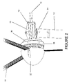
- FIG. 2 is a close up isometric view of a typical wind turbine in accordance with the invention.
- FIG. 3 is a side sectional view of a generator in accordance with the invention.
- FIG. 4 is a front plan view of a generator in accordance with the invention.
- FIG. 5 is curve representing the power generating efficiency of a wind turbine in accordance with the invention.
- FIG. 6 is a simplified electrical schematic in accordance with the invention.
- a direct drive induction wind generator 10 may be pivotally disposed at the top distal end of tower 12 extending upwardly from the ground such that a plurality of airfoils or blades 20 may be acted upon by the wind.
- a fairing 18 may be provided to house the components of the generator 10 and also reduce aerodynamic forces and disturbances proximate to the airfoils 20 .
- this particular embodiment depicts an upwind turbine design, which means a tail boom 14 is disposed on the wind generator 10 and a tail 16 is affixed to an end of the tail boom 14 to pivot the generator 10 and the airfoils 20 so that they face into the wind.
- a down wind configuration may be employed such that the airfoils 20 face downstream relative to the wind.
- There are also other means for aligning the airfoils 20 with the wind and all such means are fully contemplated by the invention.
- a tail pivot 13 ( FIG. 2 ) may be provided which is configured to allow the generator 10 to pivot out of the wind at a predetermined wind speed to protect the wind turbine from damage in the event of high winds.
- a pivot 24 may be provided at the top distal end of the tower 12 , which is configured to allow the generator 10 to rotate as required to properly align with the wind.
- a nose cone 22 may be provided adjacent the airfoils 20 to further reduce drag and turbulence and also reduce wind disturbances near the generator 10 .
- a stator 36 may be affixed to a tower fitting 15 in any well known manner.
- the stator 36 may be disposed internal to a rotor 38 .
- the rotor 38 may be affixed to the plurality of airfoils 20 in any well known manner, and may be configured to rotate at the same speed as the airfoils 20 .
- This is generally termed a “direct drive” generator, because no gear box or belt and pulley arrangement is employed to reduce or increase the speed of the rotor 38 in relation to the airfoils 20 . Elimination of these drive components greatly simplifies the generator, reduces the cost to produce and maintain the generator, and increases the generator's reliability significantly.
- a fixed stator 36 is rigidly affixed to a main shaft 28 .
- the main shaft 28 may extend coaxially through the center area of the cylindrical stator 36 .
- the main shaft 28 may be affixed to the tower fitting 15 ( FIG. 2 ) by means of a mounting flange 42 .
- a plurality of mounting holes may be provided in mounting flange 42 for the insertion of hardware fasteners to rigidly affix the main shaft 28 to the tower fitting 15 .
- a hub plate 26 may be coaxially affixed to a bearing housing 30 by any well known means.
- the bearing housing 30 is configured to be installed onto the main shaft 28 and may interface with a pair of bearings 32 .
- the bearings 32 may be configured to reduce the rotational friction between the main shaft 28 and the hub plate 26 as the hub plate rotates about the main shaft 28 .
- a bolt and washer 33 may be inserted into an end of the main shaft 28 to retain one of the bearings 32 .
- a bearing cap 34 may be affixed to and seal the open end of the bearing housing 30 .
- a plurality of mounting studs 31 protrude from the hub plate 26 .
- the mounting studs 31 may be configured to interface with and affix a typical air foil 20 to the hub plate 26 such that the hub plate 26 will rotate due to wind forces acting on the air foils 20 .
- this is a direct drive generator, the rotational speed of the air foils 20 is equal to the rotational speed of the hub plate 26 and thusly the rotational speed of the rotor 38 .
- the rotor 38 is affixed to the hub plate 26 such that it may rotate along the major axis of the main shaft 28 in close proximity to the outside periphery of the stator 36 .
- the space between the stator 36 and the rotor 38 is a critical dimension that is important to the overall efficiency of the generator 10 .
- the placement of the rotor 38 to the outside of the stator 36 allows the number of poles 44 provided in the rotor 38 to be easily modified to arrive at an optimum generator performance for a given wind speed situation.
- an induction generator as described herein requires no synchronization or voltage regulation circuitry to couple its output to a power line. It inherently functions as a generator when it is driven above its synchronization speed, a speed equal to the frequency of the power line divided by the number of pairs of poles that it contains. Therefore, by changing the number of poles 44 in the rotor 38 , the synchronous speed of the generator 10 can be modified to match a given wind speed condition for a given site location. This allows the generator 10 to operate at its optimum rotational speed and will greatly increase the amount of electricity generated at a given site.
- the rotor 38 may be a typical squirrel cage type rotor which is comprised of a pair of copper rings 39 located at each face of the rotor 38 .
- the pair of copper rings 39 may be interconnected along their outside circumference by a plurality of electrically conductive bars 43 spaced along the periphery of the copper rings 39 .
- a squirrel cage rotor is the rotating part commonly used in induction generators such as described here. In overall shape it may be cylindrical and mounted on the main shaft 28 . Internally it contains longitudinal conductive bars 43 usually comprised of aluminum or copper set into grooves and connected together at both ends by the copper rings 39 forming a cage-like shape.
- the core of the rotor 38 may be built of a stack of iron laminations 45 .
- a plurality of field windings 46 configured to create a plurality of electromagnets in the stator 36 set up a rotating magnetic field around the rotor 38 . The relative motion between this field and the rotation of the rotor 38 induces electrical current flow in the conductive bars 43 .
- the iron laminations 45 serve to carry the magnetic field across the generator. In structure and material the laminations 45 are designed to minimize losses.
- the thin laminations which may be separated by varnish insulation, reduce stray circulating currents that may result in eddy current loss.
- the material may be a low carbon but high silicon iron with several times the resistance of pure iron, further reducing eddy-current loss. The low carbon content makes it a magnetically soft material with low hysteresis loss.
- FIG. 6 depicts a simplified electrical schematic of a typical wind turbine installation in accordance with this invention
- the generator 10 is first connected to a wind turbine disconnect switch 50 .
- the disconnect switch 50 should be easily accessible so that the generator may be quickly and easily electrically disconnected for safety reasons while the turbine is being serviced.
- the disconnect switch 50 is then connected to the controller 52 .
- Housed inside the controller 52 is a line actuated contactor 54 and a current and ground fault safety control 56 .
- the controller 52 may be of the type described in U.S. Pat. No. 3,860,858 to Nola, which is incorporated herein by reference.
- the controller 52 may be a variable frequency inverter for controlling an induction generator which varies the voltage in response to varying torque requirements so that the applied voltage amplitude are of optimal value for any load and speed requirement.
- the controller 52 will sense the rotation speed of the generator. As the wind speed increases, and the generator output approaches the line frequency (60 Hz), the controller 52 will begin to synchronize the generator output to the line frequency. At synchronous speed, the controller 52 will increase the voltage level to cause power to be generated by the generator 10 and feed the power to the electrical grid. As the wind speed increases, the voltage level will continue to increase leading to the generation of more power which loads the generator 10 to keep it synchronized to the electrical grid frequency. It should also be noted that as the wind speed increases, the angle of attack of the air foils 20 with respect to the wind may change causing the airfoils 20 to become less aerodynamic which will also act to control the rotational speed of the generator 10 .
- the controller 52 utilizes a power factor controller to adjust the voltage level of the generator 10 .
- An induction generator operating at greater than synchronous speed (+percent slip) will produce a lagging power factor less than one, which should be controlled.
- the controller 52 is configured to maximize the overall performance of the generator 10 .
- a wind turbine electrical meter 58 which may be configured to measure the amount of electrical power generated by the generator 10 .
- a breaker enclosure 60 which may house the connections to a plurality of loads 62 , such as lights, cooling machines, etc. typically found in a consumer's home. This is the connection where the owner of the generator 10 would reap the benefits of the power generated by the generator 10 because it would reduce or eliminate the need to purchase power from the utility.
- a thermal breaker 64 housed in the breaker enclosure 60 which is configured to protect the system due to overheating of the components.
- FIG. 6 depicts a simplified generating system that may be required to both generate power with the generator 10 and obtain power from a utility 70 .
- FIG. 5 depicts a representative efficiency curve of a generator system in accordance with the invention which is configured to generate in the 3 kW range.
- the curve 72 clearly shows, based upon actual experimental measurements, the efficiency of the generator 10 is almost constant between 70-80% regardless of the actual power generation level. This efficiency performance is in stark contrast to the performance of a typical generator as shown by curve 74 . This improved efficiency performance translates into the generation of more power at a range of wind speeds, thereby increasing the output of the generator 10 .
Abstract
Description
Claims (35)
Priority Applications (1)
| Application Number | Priority Date | Filing Date | Title |
|---|---|---|---|
| US11/205,386 US7633176B1 (en) | 2005-08-17 | 2005-08-17 | Direct drive induction electrical power generator |
Applications Claiming Priority (1)
| Application Number | Priority Date | Filing Date | Title |
|---|---|---|---|
| US11/205,386 US7633176B1 (en) | 2005-08-17 | 2005-08-17 | Direct drive induction electrical power generator |
Publications (1)
| Publication Number | Publication Date |
|---|---|
| US7633176B1 true US7633176B1 (en) | 2009-12-15 |
Family
ID=41403263
Family Applications (1)
| Application Number | Title | Priority Date | Filing Date |
|---|---|---|---|
| US11/205,386 Expired - Fee Related US7633176B1 (en) | 2005-08-17 | 2005-08-17 | Direct drive induction electrical power generator |
Country Status (1)
| Country | Link |
|---|---|
| US (1) | US7633176B1 (en) |
Cited By (7)
| Publication number | Priority date | Publication date | Assignee | Title |
|---|---|---|---|---|
| US20090166451A1 (en) * | 2007-12-27 | 2009-07-02 | Lindsay Corporation | Wind-Powered Irrigation Machine |
| US20090174186A1 (en) * | 2006-09-14 | 2009-07-09 | Anders Nyborg | Method For Controlling A Wind Turbine Connected To The Utility Grid, Wind Turbine And Wind Park |
| US20100133820A1 (en) * | 2009-08-11 | 2010-06-03 | Jason Tsao | Solar and wind energy converter |
| US20100286835A1 (en) * | 2008-06-30 | 2010-11-11 | Vestas Wind Systems A/S | Power curtailment of wind turbines |
| CN102305180A (en) * | 2011-08-31 | 2012-01-04 | 国电联合动力技术有限公司 | Control method and system of differential gear box speed regulation type synchro wind generating set |
| US20150017016A1 (en) * | 2013-07-10 | 2015-01-15 | Haynie Prince Beall | Direct drive wind turbine |
| US11293410B1 (en) | 2021-07-28 | 2022-04-05 | Breezy Wind Turbines LLC | Direct drive wind turbine |
Citations (43)
| Publication number | Priority date | Publication date | Assignee | Title |
|---|---|---|---|---|
| US1633166A (en) * | 1922-04-03 | 1927-06-21 | Allis Chalmers Mfg Co | Power installation |
| US2431223A (en) * | 1943-09-22 | 1947-11-18 | English Electric Co Ltd | Heteropolar inductor alternator |
| US3361953A (en) * | 1964-04-09 | 1968-01-02 | Bronzavia Sa | Device for the control and regulation of the normal operating voltage of an asynchronous alternator |
| US3860858A (en) | 1973-12-19 | 1975-01-14 | Nasa | Variable frequency inverter for ac induction motors with torque, speed and braking control |
| US3940646A (en) * | 1974-03-28 | 1976-02-24 | A. O. Smith Corporation | Single-phase induction motor |
| US4205235A (en) | 1978-03-06 | 1980-05-27 | The United States Of America As Represented By The Secretary Of The Navy | Automatic electrical load matching device for wind generators |
| US4242628A (en) | 1978-05-30 | 1980-12-30 | The Regents Of The University Of Minnesota | Wind energy conversion system |
| US4291233A (en) * | 1980-01-29 | 1981-09-22 | Westinghouse Electric Corp. | Wind turbine-generator |
| JPS56151279A (en) * | 1980-04-25 | 1981-11-24 | Hitachi Ltd | Starting method for hydroelectric power generating device |
| US4345159A (en) * | 1980-07-15 | 1982-08-17 | Gutierrez Atencio Francisco J | Hydropowered bulkhead |
| US4388585A (en) * | 1981-03-16 | 1983-06-14 | The United States Of America As Represented By The Administrator Of The National Aeronautics And Space Administration | Electrical power generating system |
| US4408958A (en) * | 1980-12-23 | 1983-10-11 | The Bendix Corporation | Wind turbine blade |
| US4454465A (en) * | 1981-04-29 | 1984-06-12 | Teledyne Walterboro, A Division Of Teledyne Industries, Inc. | Electric generator that operates with few ampere-turns in field winding |
| JPS59148597A (en) * | 1983-02-12 | 1984-08-25 | Hitachi Ltd | Controller for induction machine |
| US4473792A (en) | 1981-03-16 | 1984-09-25 | The United States Of America As Represented By The Administrator Of The National Aeronautics And Space Administration | Coupling an induction motor type generator to A.C. power lines |
| US4613763A (en) | 1984-12-24 | 1986-09-23 | Swansen Theodore L | Wind driven electric power generating system |
| US4613762A (en) | 1984-12-11 | 1986-09-23 | The United States Of America As Represented By The Secretary Of Agriculture | Output responsive field control for wind-driven alternators and generators |
| DE3629872A1 (en) * | 1986-09-02 | 1988-03-10 | Licentia Gmbh | Wind-power installation for generating electrical energy |
| DE3638129A1 (en) * | 1986-11-08 | 1988-05-11 | Licentia Gmbh | Large diameter turbogenerator for generating electrical energy at high power |
| US5029288A (en) | 1988-04-22 | 1991-07-02 | Hitachi, Ltd. | Method and apparatus for operating a variable speed power generation system |
| US5295793A (en) * | 1992-03-02 | 1994-03-22 | Telect, Inc. | Wind turbine |
| US5315159A (en) * | 1989-10-12 | 1994-05-24 | Holec Projects B.V. | Wind turbine |
| US5406190A (en) | 1991-11-07 | 1995-04-11 | Siemens Aktiengesellschaft | Device for generating electrical energy having an A.C. generator coupled to a turbine |
| US5525894A (en) * | 1992-08-03 | 1996-06-11 | Heller-Dejulio Corporation | Rotary induction generator adapted to be driven by a prime mover for generating electric power |
| US5587643A (en) * | 1988-07-12 | 1996-12-24 | Heller Dejulio Corporation | Rotary induction machine having control of secondary winding impedance |
| US5729118A (en) * | 1994-06-17 | 1998-03-17 | Kabushiki Kaisha Toshiba | Variable speed induction generator-motor with controllable excitation frequency |
| JPH10225096A (en) * | 1997-02-13 | 1998-08-21 | Sawafuji Electric Co Ltd | Retarder |
| US5986438A (en) * | 1998-04-21 | 1999-11-16 | Heller-Dejulio Corporation | Rotary induction machine having control of secondary winding impedance |
| US6020725A (en) * | 1996-04-25 | 2000-02-01 | Lifeline Enterprises L.L.C. | Self-excited asynchronous alternating current generator with paramutual inductive coupling |
| US6087753A (en) * | 1998-05-11 | 2000-07-11 | Active Power, Inc. | High-efficiency inductor-alternator |
| US6285090B1 (en) * | 1997-03-10 | 2001-09-04 | Jeumont Industrie | Low-speed directly driven wind turbine |
| US6429612B1 (en) | 2000-03-30 | 2002-08-06 | Yaskawa Electric America, Inc. | Fast stopping method for induction motors operating from variable frequency drives |
| US6641327B1 (en) * | 1998-01-28 | 2003-11-04 | Abb Oy | Water turbine arrangement |
| US6815934B2 (en) * | 2001-10-01 | 2004-11-09 | Haynes Beffel & Wolfeld Llp | Induction generator power supply |
| US6840734B2 (en) * | 2000-03-08 | 2005-01-11 | Forskningscenter Riso | Method of operating a turbine |
| US6943462B2 (en) * | 2000-03-11 | 2005-09-13 | Aloys Wobben | Ring generator for a wind power installation |
| US7042109B2 (en) * | 2002-08-30 | 2006-05-09 | Gabrys Christopher W | Wind turbine |
| US20070063677A1 (en) * | 2005-09-16 | 2007-03-22 | Satcon Technology Corporation | Slip-controlled, wound-rotor induction machine for wind turbine and other applications |
| US20070102934A1 (en) * | 2005-11-07 | 2007-05-10 | Enrique Pescarmona | Integrated wind power generator |
| US20080007070A1 (en) * | 2000-11-15 | 2008-01-10 | Edelson Jonathan S | Chimney turbine |
| US7330016B2 (en) * | 2001-10-01 | 2008-02-12 | Colley Bruce H | Induction generator power supply |
| US20080054733A1 (en) * | 2004-05-12 | 2008-03-06 | Edelson Jonathan S | Slotless Ac Induction Motor |
| US20080309090A1 (en) * | 2005-07-28 | 2008-12-18 | Cleanfield Energy Corporation | Power Generating System Including Modular Wind Turbine-Generator Assembly |
-
2005
- 2005-08-17 US US11/205,386 patent/US7633176B1/en not_active Expired - Fee Related
Patent Citations (44)
| Publication number | Priority date | Publication date | Assignee | Title |
|---|---|---|---|---|
| US1633166A (en) * | 1922-04-03 | 1927-06-21 | Allis Chalmers Mfg Co | Power installation |
| US2431223A (en) * | 1943-09-22 | 1947-11-18 | English Electric Co Ltd | Heteropolar inductor alternator |
| US3361953A (en) * | 1964-04-09 | 1968-01-02 | Bronzavia Sa | Device for the control and regulation of the normal operating voltage of an asynchronous alternator |
| US3860858A (en) | 1973-12-19 | 1975-01-14 | Nasa | Variable frequency inverter for ac induction motors with torque, speed and braking control |
| US3940646A (en) * | 1974-03-28 | 1976-02-24 | A. O. Smith Corporation | Single-phase induction motor |
| US4205235A (en) | 1978-03-06 | 1980-05-27 | The United States Of America As Represented By The Secretary Of The Navy | Automatic electrical load matching device for wind generators |
| US4242628A (en) | 1978-05-30 | 1980-12-30 | The Regents Of The University Of Minnesota | Wind energy conversion system |
| US4291233A (en) * | 1980-01-29 | 1981-09-22 | Westinghouse Electric Corp. | Wind turbine-generator |
| JPS56151279A (en) * | 1980-04-25 | 1981-11-24 | Hitachi Ltd | Starting method for hydroelectric power generating device |
| US4345159A (en) * | 1980-07-15 | 1982-08-17 | Gutierrez Atencio Francisco J | Hydropowered bulkhead |
| US4408958A (en) * | 1980-12-23 | 1983-10-11 | The Bendix Corporation | Wind turbine blade |
| US4388585A (en) * | 1981-03-16 | 1983-06-14 | The United States Of America As Represented By The Administrator Of The National Aeronautics And Space Administration | Electrical power generating system |
| US4473792A (en) | 1981-03-16 | 1984-09-25 | The United States Of America As Represented By The Administrator Of The National Aeronautics And Space Administration | Coupling an induction motor type generator to A.C. power lines |
| US4454465A (en) * | 1981-04-29 | 1984-06-12 | Teledyne Walterboro, A Division Of Teledyne Industries, Inc. | Electric generator that operates with few ampere-turns in field winding |
| JPS59148597A (en) * | 1983-02-12 | 1984-08-25 | Hitachi Ltd | Controller for induction machine |
| US4613762A (en) | 1984-12-11 | 1986-09-23 | The United States Of America As Represented By The Secretary Of Agriculture | Output responsive field control for wind-driven alternators and generators |
| US4613763A (en) | 1984-12-24 | 1986-09-23 | Swansen Theodore L | Wind driven electric power generating system |
| DE3629872A1 (en) * | 1986-09-02 | 1988-03-10 | Licentia Gmbh | Wind-power installation for generating electrical energy |
| DE3638129A1 (en) * | 1986-11-08 | 1988-05-11 | Licentia Gmbh | Large diameter turbogenerator for generating electrical energy at high power |
| US5029288A (en) | 1988-04-22 | 1991-07-02 | Hitachi, Ltd. | Method and apparatus for operating a variable speed power generation system |
| US5587643A (en) * | 1988-07-12 | 1996-12-24 | Heller Dejulio Corporation | Rotary induction machine having control of secondary winding impedance |
| US5315159A (en) * | 1989-10-12 | 1994-05-24 | Holec Projects B.V. | Wind turbine |
| US5406190A (en) | 1991-11-07 | 1995-04-11 | Siemens Aktiengesellschaft | Device for generating electrical energy having an A.C. generator coupled to a turbine |
| US5295793A (en) * | 1992-03-02 | 1994-03-22 | Telect, Inc. | Wind turbine |
| US5525894A (en) * | 1992-08-03 | 1996-06-11 | Heller-Dejulio Corporation | Rotary induction generator adapted to be driven by a prime mover for generating electric power |
| US5729118A (en) * | 1994-06-17 | 1998-03-17 | Kabushiki Kaisha Toshiba | Variable speed induction generator-motor with controllable excitation frequency |
| US6020725A (en) * | 1996-04-25 | 2000-02-01 | Lifeline Enterprises L.L.C. | Self-excited asynchronous alternating current generator with paramutual inductive coupling |
| JPH10225096A (en) * | 1997-02-13 | 1998-08-21 | Sawafuji Electric Co Ltd | Retarder |
| US6285090B1 (en) * | 1997-03-10 | 2001-09-04 | Jeumont Industrie | Low-speed directly driven wind turbine |
| US6641327B1 (en) * | 1998-01-28 | 2003-11-04 | Abb Oy | Water turbine arrangement |
| US6163137A (en) * | 1998-04-21 | 2000-12-19 | Heller-Dejulio Corporation | Rotary induction machine having control of secondary winding impedance |
| US5986438A (en) * | 1998-04-21 | 1999-11-16 | Heller-Dejulio Corporation | Rotary induction machine having control of secondary winding impedance |
| US6087753A (en) * | 1998-05-11 | 2000-07-11 | Active Power, Inc. | High-efficiency inductor-alternator |
| US6840734B2 (en) * | 2000-03-08 | 2005-01-11 | Forskningscenter Riso | Method of operating a turbine |
| US6943462B2 (en) * | 2000-03-11 | 2005-09-13 | Aloys Wobben | Ring generator for a wind power installation |
| US6429612B1 (en) | 2000-03-30 | 2002-08-06 | Yaskawa Electric America, Inc. | Fast stopping method for induction motors operating from variable frequency drives |
| US20080007070A1 (en) * | 2000-11-15 | 2008-01-10 | Edelson Jonathan S | Chimney turbine |
| US6815934B2 (en) * | 2001-10-01 | 2004-11-09 | Haynes Beffel & Wolfeld Llp | Induction generator power supply |
| US7330016B2 (en) * | 2001-10-01 | 2008-02-12 | Colley Bruce H | Induction generator power supply |
| US7042109B2 (en) * | 2002-08-30 | 2006-05-09 | Gabrys Christopher W | Wind turbine |
| US20080054733A1 (en) * | 2004-05-12 | 2008-03-06 | Edelson Jonathan S | Slotless Ac Induction Motor |
| US20080309090A1 (en) * | 2005-07-28 | 2008-12-18 | Cleanfield Energy Corporation | Power Generating System Including Modular Wind Turbine-Generator Assembly |
| US20070063677A1 (en) * | 2005-09-16 | 2007-03-22 | Satcon Technology Corporation | Slip-controlled, wound-rotor induction machine for wind turbine and other applications |
| US20070102934A1 (en) * | 2005-11-07 | 2007-05-10 | Enrique Pescarmona | Integrated wind power generator |
Non-Patent Citations (6)
| Title |
|---|
| Automatic translation of JP 10-225096 A to Osada et al., published Aug. 21, 1998. * |
| Fax from Law Office of James M Leas dated Oct. 10, 2009. * |
| H. Wayne Beaty et al.. Electric Motor Handbook., 1998 edition. pp. 42, 105, 297, 298. * |
| L. H. Hansen et al., "Conceptual survey of Generators and Power Electronics for Wind Turbines," Riso National Laboratory Roskilde, Denmark Dec. 2001 RISO-1205(EN). |
| M. R. Dubois, "Review of Electromechanical Conversion in Wind Turbines," Report EPP00.R03, TU Delft, Faculty ITS, Group Electrical Power Processing, Mekelweg 4, 2628 CD Delft, Nederland, Kamer LB 03.660, Apr. 2000. |
| Y. Amirat, et al. "Generators for Wind Energy Conversion Systems: State of the Art and Coming Attractions," J. Electrical Systems 3-1 (2007). |
Cited By (13)
| Publication number | Priority date | Publication date | Assignee | Title |
|---|---|---|---|---|
| US7851934B2 (en) * | 2006-09-14 | 2010-12-14 | Vestas Wind Systems A/S | Method for controlling a wind turbine connected to the utility grid, wind turbine and wind park |
| US20090174186A1 (en) * | 2006-09-14 | 2009-07-09 | Anders Nyborg | Method For Controlling A Wind Turbine Connected To The Utility Grid, Wind Turbine And Wind Park |
| US20090166451A1 (en) * | 2007-12-27 | 2009-07-02 | Lindsay Corporation | Wind-Powered Irrigation Machine |
| US8793027B2 (en) * | 2008-06-30 | 2014-07-29 | Vestas Wind Systems A/S | Power curtailment of wind turbines |
| US20100286835A1 (en) * | 2008-06-30 | 2010-11-11 | Vestas Wind Systems A/S | Power curtailment of wind turbines |
| US7851935B2 (en) * | 2009-08-11 | 2010-12-14 | Jason Tsao | Solar and wind energy converter |
| US7964981B2 (en) * | 2009-08-11 | 2011-06-21 | Jason Tsao | Solar and wind energy converter |
| US20100133820A1 (en) * | 2009-08-11 | 2010-06-03 | Jason Tsao | Solar and wind energy converter |
| CN102305180A (en) * | 2011-08-31 | 2012-01-04 | 国电联合动力技术有限公司 | Control method and system of differential gear box speed regulation type synchro wind generating set |
| CN102305180B (en) * | 2011-08-31 | 2013-07-31 | 国电联合动力技术有限公司 | Control method and system of differential gear box speed regulation type synchro wind generating set |
| US20150017016A1 (en) * | 2013-07-10 | 2015-01-15 | Haynie Prince Beall | Direct drive wind turbine |
| US11293410B1 (en) | 2021-07-28 | 2022-04-05 | Breezy Wind Turbines LLC | Direct drive wind turbine |
| US11629700B2 (en) | 2021-07-28 | 2023-04-18 | Breezy Wind Turbines LLC | Direct drive wind turbine |
Similar Documents
| Publication | Publication Date | Title |
|---|---|---|
| Muljadi et al. | Power quality issues in a hybrid power system | |
| Polinder et al. | Comparison of direct-drive and geared generator concepts for wind turbines | |
| US7633176B1 (en) | Direct drive induction electrical power generator | |
| US8138619B2 (en) | Non-grid-connected wind turbine with double-stator double-salient brushless dc-generator | |
| CN102035309A (en) | Method and apparatus for generating power in a wind turbine | |
| CN100546153C (en) | Winding type external rotor brushless double feed generator and control device thereof | |
| CN101908807B (en) | Multi-winding asynchronous change-pole generator | |
| CN201344102Y (en) | Wind-power generator | |
| CN201045750Y (en) | External rotor brushless dual-feed generator and controller thereof | |
| Hlaing | Basic concepts of doubly fed induction generator driven by wind energy conversion system | |
| CN110601479B (en) | Double-rotor induction wind driven generator and working method thereof | |
| CN107681828A (en) | A kind of double rotor speed regulating wind generator system and its control method | |
| CN101051779B (en) | Winding type internal rotor brushless double feed generator and its control device | |
| CN207265812U (en) | A kind of double rotor speed regulating wind generator system | |
| CN207053364U (en) | A kind of permanent magnet coupling buncher | |
| Chen | Wind turbine drive train systems | |
| CN101546981B (en) | Vertical wind power generator with motor startup mode | |
| CN201425001Y (en) | 1.5-MW permanent magnet direct-drive wind-driven power generator unit | |
| CN108282120A (en) | Double-stator permanent magnet synchronous generator control system and method for wind-power electricity generation | |
| CN100557941C (en) | Winding brushless double feed generator controller | |
| CN201038960Y (en) | Internal rotor brushless and double-fed generator and its control device | |
| CN103001427A (en) | High-power hybrid-excitation bi-rotor double-fed synchronous wind driven generator | |
| Verma et al. | Theoretical approach for comparison of various types of wind generator systems | |
| Polinder et al. | Generator systems for wind turbines | |
| Ramya et al. | Effectual and Lossless Electrical Power Generation Methodology using Wind-Lens Technology |
Legal Events
| Date | Code | Title | Description |
|---|---|---|---|
| AS | Assignment |
Owner name: EARTH TURBINES, INC., VERMONT Free format text: ASSIGNMENT OF ASSIGNORS INTEREST;ASSIGNOR:BLITTERSDORF, DAVID C;REEL/FRAME:023443/0796 Effective date: 20091027 |
|
| STCF | Information on status: patent grant |
Free format text: PATENTED CASE |
|
| FPAY | Fee payment |
Year of fee payment: 4 |
|
| FPAY | Fee payment |
Year of fee payment: 8 |
|
| FEPP | Fee payment procedure |
Free format text: MAINTENANCE FEE REMINDER MAILED (ORIGINAL EVENT CODE: REM.); ENTITY STATUS OF PATENT OWNER: SMALL ENTITY |
|
| LAPS | Lapse for failure to pay maintenance fees |
Free format text: PATENT EXPIRED FOR FAILURE TO PAY MAINTENANCE FEES (ORIGINAL EVENT CODE: EXP.); ENTITY STATUS OF PATENT OWNER: SMALL ENTITY |
|
| STCH | Information on status: patent discontinuation |
Free format text: PATENT EXPIRED DUE TO NONPAYMENT OF MAINTENANCE FEES UNDER 37 CFR 1.362 |
|
| FP | Lapsed due to failure to pay maintenance fee |
Effective date: 20211215 |