US7581926B1 - Servo-controlled extender mechanism for extendable rotor blades for power generating wind and ocean current turbines - Google Patents
Servo-controlled extender mechanism for extendable rotor blades for power generating wind and ocean current turbines Download PDFInfo
- Publication number
- US7581926B1 US7581926B1 US11/084,640 US8464005A US7581926B1 US 7581926 B1 US7581926 B1 US 7581926B1 US 8464005 A US8464005 A US 8464005A US 7581926 B1 US7581926 B1 US 7581926B1
- Authority
- US
- United States
- Prior art keywords
- blade
- rotor
- extender
- pinion
- rack gear
- Prior art date
- Legal status (The legal status is an assumption and is not a legal conclusion. Google has not performed a legal analysis and makes no representation as to the accuracy of the status listed.)
- Expired - Fee Related, expires
Links
- 239000004606 Fillers/Extenders Substances 0.000 title claims abstract description 65
- 230000007246 mechanism Effects 0.000 title claims abstract description 28
- 239000012530 fluid Substances 0.000 claims abstract description 16
- 238000005096 rolling process Methods 0.000 claims 3
- XLYOFNOQVPJJNP-UHFFFAOYSA-N water Substances O XLYOFNOQVPJJNP-UHFFFAOYSA-N 0.000 description 17
- 230000000694 effects Effects 0.000 description 10
- 238000005259 measurement Methods 0.000 description 7
- 239000002023 wood Substances 0.000 description 6
- 238000006243 chemical reaction Methods 0.000 description 4
- 238000004519 manufacturing process Methods 0.000 description 4
- 230000001133 acceleration Effects 0.000 description 3
- 238000012423 maintenance Methods 0.000 description 3
- 238000000034 method Methods 0.000 description 3
- 230000001105 regulatory effect Effects 0.000 description 3
- 230000009471 action Effects 0.000 description 2
- 230000004913 activation Effects 0.000 description 2
- 238000005452 bending Methods 0.000 description 2
- 230000008878 coupling Effects 0.000 description 2
- 238000010168 coupling process Methods 0.000 description 2
- 238000005859 coupling reaction Methods 0.000 description 2
- 238000010586 diagram Methods 0.000 description 2
- 230000005611 electricity Effects 0.000 description 2
- 230000002441 reversible effect Effects 0.000 description 2
- 230000001360 synchronised effect Effects 0.000 description 2
- AYCPARAPKDAOEN-LJQANCHMSA-N N-[(1S)-2-(dimethylamino)-1-phenylethyl]-6,6-dimethyl-3-[(2-methyl-4-thieno[3,2-d]pyrimidinyl)amino]-1,4-dihydropyrrolo[3,4-c]pyrazole-5-carboxamide Chemical compound C1([C@H](NC(=O)N2C(C=3NN=C(NC=4C=5SC=CC=5N=C(C)N=4)C=3C2)(C)C)CN(C)C)=CC=CC=C1 AYCPARAPKDAOEN-LJQANCHMSA-N 0.000 description 1
- 230000001154 acute effect Effects 0.000 description 1
- 230000006978 adaptation Effects 0.000 description 1
- 238000009411 base construction Methods 0.000 description 1
- 230000008901 benefit Effects 0.000 description 1
- 230000008859 change Effects 0.000 description 1
- 238000004891 communication Methods 0.000 description 1
- 230000002860 competitive effect Effects 0.000 description 1
- 238000010276 construction Methods 0.000 description 1
- 230000001276 controlling effect Effects 0.000 description 1
- 238000013016 damping Methods 0.000 description 1
- 230000003247 decreasing effect Effects 0.000 description 1
- 230000000994 depressogenic effect Effects 0.000 description 1
- 230000007613 environmental effect Effects 0.000 description 1
- 239000011152 fibreglass Substances 0.000 description 1
- 230000009931 harmful effect Effects 0.000 description 1
- 238000009434 installation Methods 0.000 description 1
- 230000003014 reinforcing effect Effects 0.000 description 1
- 230000008439 repair process Effects 0.000 description 1
- 230000004044 response Effects 0.000 description 1
- 238000000926 separation method Methods 0.000 description 1
- 239000003351 stiffener Substances 0.000 description 1
- 230000000007 visual effect Effects 0.000 description 1
Images


Classifications
-
- F—MECHANICAL ENGINEERING; LIGHTING; HEATING; WEAPONS; BLASTING
- F03—MACHINES OR ENGINES FOR LIQUIDS; WIND, SPRING, OR WEIGHT MOTORS; PRODUCING MECHANICAL POWER OR A REACTIVE PROPULSIVE THRUST, NOT OTHERWISE PROVIDED FOR
- F03D—WIND MOTORS
- F03D7/00—Controlling wind motors
- F03D7/02—Controlling wind motors the wind motors having rotation axis substantially parallel to the air flow entering the rotor
- F03D7/022—Adjusting aerodynamic properties of the blades
- F03D7/0236—Adjusting aerodynamic properties of the blades by changing the active surface of the wind engaging parts, e.g. reefing or furling
-
- F—MECHANICAL ENGINEERING; LIGHTING; HEATING; WEAPONS; BLASTING
- F05—INDEXING SCHEMES RELATING TO ENGINES OR PUMPS IN VARIOUS SUBCLASSES OF CLASSES F01-F04
- F05B—INDEXING SCHEME RELATING TO WIND, SPRING, WEIGHT, INERTIA OR LIKE MOTORS, TO MACHINES OR ENGINES FOR LIQUIDS COVERED BY SUBCLASSES F03B, F03D AND F03G
- F05B2240/00—Components
- F05B2240/20—Rotors
- F05B2240/202—Rotors with adjustable area of intercepted fluid
- F05B2240/2021—Rotors with adjustable area of intercepted fluid by means of telescoping blades
-
- F—MECHANICAL ENGINEERING; LIGHTING; HEATING; WEAPONS; BLASTING
- F05—INDEXING SCHEMES RELATING TO ENGINES OR PUMPS IN VARIOUS SUBCLASSES OF CLASSES F01-F04
- F05B—INDEXING SCHEME RELATING TO WIND, SPRING, WEIGHT, INERTIA OR LIKE MOTORS, TO MACHINES OR ENGINES FOR LIQUIDS COVERED BY SUBCLASSES F03B, F03D AND F03G
- F05B2240/00—Components
- F05B2240/20—Rotors
- F05B2240/30—Characteristics of rotor blades, i.e. of any element transforming dynamic fluid energy to or from rotational energy and being attached to a rotor
-
- F—MECHANICAL ENGINEERING; LIGHTING; HEATING; WEAPONS; BLASTING
- F05—INDEXING SCHEMES RELATING TO ENGINES OR PUMPS IN VARIOUS SUBCLASSES OF CLASSES F01-F04
- F05B—INDEXING SCHEME RELATING TO WIND, SPRING, WEIGHT, INERTIA OR LIKE MOTORS, TO MACHINES OR ENGINES FOR LIQUIDS COVERED BY SUBCLASSES F03B, F03D AND F03G
- F05B2270/00—Control
- F05B2270/60—Control system actuates through
-
- Y—GENERAL TAGGING OF NEW TECHNOLOGICAL DEVELOPMENTS; GENERAL TAGGING OF CROSS-SECTIONAL TECHNOLOGIES SPANNING OVER SEVERAL SECTIONS OF THE IPC; TECHNICAL SUBJECTS COVERED BY FORMER USPC CROSS-REFERENCE ART COLLECTIONS [XRACs] AND DIGESTS
- Y02—TECHNOLOGIES OR APPLICATIONS FOR MITIGATION OR ADAPTATION AGAINST CLIMATE CHANGE
- Y02E—REDUCTION OF GREENHOUSE GAS [GHG] EMISSIONS, RELATED TO ENERGY GENERATION, TRANSMISSION OR DISTRIBUTION
- Y02E10/00—Energy generation through renewable energy sources
- Y02E10/70—Wind energy
- Y02E10/72—Wind turbines with rotation axis in wind direction
-
- Y—GENERAL TAGGING OF NEW TECHNOLOGICAL DEVELOPMENTS; GENERAL TAGGING OF CROSS-SECTIONAL TECHNOLOGIES SPANNING OVER SEVERAL SECTIONS OF THE IPC; TECHNICAL SUBJECTS COVERED BY FORMER USPC CROSS-REFERENCE ART COLLECTIONS [XRACs] AND DIGESTS
- Y10—TECHNICAL SUBJECTS COVERED BY FORMER USPC
- Y10T—TECHNICAL SUBJECTS COVERED BY FORMER US CLASSIFICATION
- Y10T74/00—Machine element or mechanism
- Y10T74/18—Mechanical movements
- Y10T74/18056—Rotary to or from reciprocating or oscillating
- Y10T74/18088—Rack and pinion type
- Y10T74/18096—Shifting rack
-
- Y—GENERAL TAGGING OF NEW TECHNOLOGICAL DEVELOPMENTS; GENERAL TAGGING OF CROSS-SECTIONAL TECHNOLOGIES SPANNING OVER SEVERAL SECTIONS OF THE IPC; TECHNICAL SUBJECTS COVERED BY FORMER USPC CROSS-REFERENCE ART COLLECTIONS [XRACs] AND DIGESTS
- Y10—TECHNICAL SUBJECTS COVERED BY FORMER USPC
- Y10T—TECHNICAL SUBJECTS COVERED BY FORMER US CLASSIFICATION
- Y10T74/00—Machine element or mechanism
- Y10T74/18—Mechanical movements
- Y10T74/18568—Reciprocating or oscillating to or from alternating rotary
- Y10T74/188—Reciprocating or oscillating to or from alternating rotary including spur gear
- Y10T74/18808—Reciprocating or oscillating to or from alternating rotary including spur gear with rack
-
- Y—GENERAL TAGGING OF NEW TECHNOLOGICAL DEVELOPMENTS; GENERAL TAGGING OF CROSS-SECTIONAL TECHNOLOGIES SPANNING OVER SEVERAL SECTIONS OF THE IPC; TECHNICAL SUBJECTS COVERED BY FORMER USPC CROSS-REFERENCE ART COLLECTIONS [XRACs] AND DIGESTS
- Y10—TECHNICAL SUBJECTS COVERED BY FORMER USPC
- Y10T—TECHNICAL SUBJECTS COVERED BY FORMER US CLASSIFICATION
- Y10T74/00—Machine element or mechanism
- Y10T74/19—Gearing
- Y10T74/19642—Directly cooperating gears
- Y10T74/1967—Rack and pinion
Definitions
- This invention relates to electric power-generating devices, such as wind turbines and ocean current turbines, and more particularly to an apparatus for extending and retracting extendable rotors of horizontal axis, axial flow wind or water turbines.
- the rotor includes a rotatable housing unit mounted on a vertical shaft and provided with a pair of rotor blade units that telescope into the housing unit.
- a mechanism is provided to extend and retract the rotor blade units from the housing unit, for the purpose of providing vertical lift during takeoff and vertical landing.
- the rotor blades are mechanically coupled together so that operation of one rotor blade is necessarily accompanied by duplicate and identical operation of the other rotor blade unit to thereby avoid unbalanced application of lifting and inertia forces.
- a propeller is provided on the tail of the aircraft as in conventional helicopters.
- a plurality of rollers are provided.
- a plurality of rib stiffeners are provided to afford a stiffening action for the rotor blade elements similar to conventional aircraft wing structures.
- a coupling system ( FIG. 9 ) which comprises a rigid arm affixed to one rotor blade and a similar arm which is affixed to the opposing rotor blade element.
- These transversely disposed arms are affixed at their inner ends to an endless device, which is rotatably mounted on two sprockets located on opposite distal ends of the housing unit.
- An aircraft may take off vertically or may be landed vertically by extending the rotor blades after imparting operating movement to the housing and rotor blades about a shaft. Rotary motion is imparted to the shaft by motive means not shown. After takeoff, when sufficient altitude is obtained, a conventional power system, such as forward thrust engines, may be employed.
- the Wood patent is concerned with a stowed rotor arrangement for producing vertical lift for an aeronautical vehicle.
- the housing unit is mounted on the vehicle and rotatable about an axis, which is in general alignment with the direction of lift, using a pair of rotor blades telescopically mounted in the housing unit and disposed in generally transverse relation to the axis of rotation of the housing unit.
- Wind and water current applications are not concerned with producing vertical lift for an aeronautical vehicle.
- the rotors are mounted on a stationary structure and are rotatable about an axis, which is in general alignment with the direction of the wind or water current.
- the housing unit is mounted on the vehicle and rotatable about an axis, which is in general alignment with the direction of lift, not in alignment with the wind or water current.
- the rotors are employed in a fundamentally different way to achieve a fundamentally different result. That is, the rotors are in alignment with the wind or water with the result that the rotors are moved by the current to produce electricity.
- Wood In Wood, the rotors are in alignment with the direction of lift with the result that the rotors are moved by an engine to produce vertical lift. Wood describes a mechanism for a variable diameter rotor for aerospace applications wherein the rotor is driven by an engine and moves perpendicularly with respect to the flowing medium. Wood does not address the requirements of a wind or ocean current application, wherein the rotors are in alignment with and are driven by a flowing medium and do not move with respect to the flowing medium.
- Each blade is comprised of a hollow spar, which forms the leading edge and is the main strength member of the blade and a tapered trailing edge portion, which completes the airfoil contour of the blade.
- Each blade has a tip portion of reduced chord which has one end inserted into a cavity in the outboard end of the blade spar in which it is freely slidable. The tip portion is supported by two rollers on the spar, mounted at spaced points along its leading edge on pivots and by rollers mounted on pivots carried by the spar in position to engage the top and bottom tapered surfaces of the tip portion adjacent its trailing edge.
- each tip portion of the upper rotor is controlled by a cable or flexible strap which is attached to the inboard end of the tip portion and passes through the hollow spar to a pulley mounted in the rotor hub by which the cable is directed downward through the hollow drive shaft.
- a cable or flexible strap which is attached to the inboard end of the tip portion and passes through the hollow spar to a pulley mounted in the rotor hub by which the cable is directed downward through the hollow drive shaft.
- three cables from three blades of the upper rotor are combined into a single cable.
- the tip portions of the lower rotor are similarly controlled by cables.
- a rudder pedal is depressed, which extends one of the cables, and retracts the other cable, causing cable spools to rotate in opposite directions, one to wind up the cable(s) on one cable reel and the other to slacken its cable(s).
- the cables are held taut at all times by the rotating tip portions which are constantly urged outward regardless of their axial position by centrifugal forces generated by the rotating blades which are driven by the helicopter's engine.
- the Bielawa patent does not address problems that arise with respect to an extendable rotor blade system that is fixed with respect to the flowing medium, whether the medium is air or water or any other fluid-flow medium.
- variable diameter rotors for tilt rotors and aircraft are susceptible to fatigue failures and require extensive maintenance.
- Wind turbines and ocean current turbines operate in environmental conditions that can quickly degrade the properties of an extension mechanism.
- the high maintenance requirement translates to higher energy cost, which results in a less competitive renewable energy system.
- U.S. Pat. No. 4,180,372 of Lippert, Jr. entitled “Wind Rotor Automatic Air Brake”, granted Dec. 25, 1979 discloses a spring-loaded pivoting end plate braking mechanism for a wind rotor.
- the end plate is hinged such that it is deployed by centrifugal force or a speed change detected by a sensor which controls an actuator to effect the required positioning of the brake plate into the air stream.
- the brake plate acts as an aerodynamic brake for wind turbines in over-speed conditions.
- the brake has a stationary portion fixed on the tip of the turbine rotor and a pivoting portion hinged for movement with respect to the fixed portion.
- This patent teaches an aerodynamic windmill over-speed limiter which is located at the blade tip with its hinge axis transverse to the rotor blade chord such that the device has maximum effectiveness when deployed for braking and which, in its stowed position, acts to improve the aerodynamics of the rotor blade itself.
- the brake is located at the rotor blade tip, the drag produced by the brake is at the greatest possible rotor radius such that a maximum torque braking effect is achieved. Also, when the brake plate is deployed, the trailing edge aft of the hinge line is rotated inwardly such that it is interposed over the tip area of the rotor blade. The brake, therefore, not only produces a drag at the maximum possible moment arm but, at the same time, it destroys efficient airflow over a portion of the blade that is normally very effective in driving the rotor.
- U.S. Pat. No. 4,710,101 to Jamieson entitled “Wind Turbine” granted Dec. 1, 1987 discloses a wind turbine in which movable nose portions are located at or adjacent the leading edge of the blade and at or adjacent the tip of the blade.
- the nose portions are displaceable longitudinally of the blade, i.e. radially outwardly of the blade, from a normal retracted position. This moveable portion contributes to the lift of the airfoil section, and is moved to an advanced position in which drag is produced, to prevent unwanted increase in the speed of the rotation of the rotor.
- the movable portion when in the normal, retracted position, will have little harmful effect on the aerodynamic shape of the airfoil section, the flow lines of the air passing from the movable portion extremely smoothly onto the remainder of the airfoil section.
- the leading face of the remainder of the airfoil section has a flat or concave surface to increase the drag effect when the movable portion is in the advanced position.
- bleed passages may lead from the leading faces of the remainder of the airfoil sections, which are exposed when the movable portions are moved to the advanced position. These bleed passages can extend to a major surface of the remainder of the respective airfoil section, to cause air to flow from the leading face to said major surface to cause separation of flow and increase drag.
- the portion exposed may in fact include part of the operating mechanism of the movable portion, which would even further increase the drag effect.
- the nose portions move radially outwardly.
- the nose portions move either under the action of centrifugal force against the return force of springs, or together with assistance from actuators, and the leading faces are exposed.
- the outward movement of the nose portions will itself cause an effective reshaping of the cross-section of the blades so they do not resemble an airfoil section at all, at the tip of the blade. This destroys lift on a section of the blade where the most power is produced. It will create much more drag on the exposed section, that is the leading face, which may be contoured or roughened to produce maximum drag.
- the displaced nose sections create drag at a radius beyond the normal position of the tip, where the velocity is higher and the effectiveness is greater.
- the present invention is concerned with the opposite effect: increasing the length of the rotor blade to improve efficient airflow over the outer extremity of the blade to increase its effectiveness in driving the rotor without introducing drag or braking.
- U.S. Pat. No. 5,630,705 of Eikelenbloom entitled “Rotor Construction of Windmill” granted May 20, 1997 discloses a device for converting wind flow energy into mechanical energy.
- the device has a base construction and a rotor with a horizontal axis mounted on the base.
- the rotor has a number of elongated rotor blades, which are connected to a rotary support and extend radially therefrom.
- Each rotor blade or a part thereof is connected to the rotor support by a hinge connection for tilting the longitudinal axis of the rotor blade or part thereof to a predetermined orientation relative to the axis of rotation of the support.
- a hinge axis of the hinge connection between the rotor blade and the rotary support is directed at an acute angle both to the longitudinal axis of the rotor blade and to the axis of rotation of the support.
- the maximum wind-braking area, to be used at relatively low wind speeds, is achieved when the rotor blades are at right angles to the wind direction. Pivoting the rotor blades around their longitudinal axes into the direction of the wind results in a lower wind-braking area to be used at relatively high wind speeds.
- the rotor blades are formed by a number of elongated rotor blade parts, which are to be placed in a position fully or partially overlapping each other in the lengthwise direction, or essentially in line with each other.
- the component parts of the rotor blade fully overlap each other.
- a maximum length of such a rotor blade is achieved if all component rotor blade parts are placed in line with each other.
- FIG. 5 of Eikelenboom illustrates an elongated, hollow first rotor blade part that is hingedly connected to an arm.
- the first rotor blade part contains an elongated, hollow second rotor blade part.
- the second rotor blade part can in turn contain an elongated third rotor blade part.
- the rotor blade parts can be shifted relative to each other in the lengthwise direction by separate mechanisms including a motor drive, a spindle and a wire cable for each moveable part fitted in the first rotor blade part.
- the wire is wound on the spindle.
- the wires can be subjected to both tensile stress and pressure, and a separate wire, spindle, motor arrangement is connected is to the first and second rotor blade parts, respectively, for the purpose of shifting the rotor blade parts in and out relative to each other.
- a disadvantage of the device shown FIG. 5 of Eikelenboom is that the first rotor blade into which the second blade part slide must be completely hollow in order to accommodate the shape of the second blade.
- the blades are of such a size that reinforcing rib supports are necessary to obtain strength in large-scale wind and water current applications.
- the cable mechanism itself is not suitable for large scale turbines because the wires must be capable of being subjected to both tensile stress and pressure and such cables are not available for moving heavy objects.
- Prior mechanisms for moving the extension blades of variable diameter rotor blades have used endless belts, wire cables, and lead-screw mechanisms attached to the extender blade.
- Endless belts have the disadvantage of having to extend to the distal end of the main blade in order to effect the desired maximum of longitudinal movement, are complex to manufacture and add undesired additional weight to the outer reaches of the main blade.
- Wire cables have the disadvantage of requiring two cables, one to move the extender blade out and one to pull the extender blade in. Also the cables are heavy for required strength, have to extend to the distal end of the main blade in order to effect the desired extent of longitudinal movement, are complex to manufacture and add undesired additional weight to the outer reaches of the main blade.
- Lead screw mechanisms incorporate a slider nut driven by a threaded lead screw.
- Lead screw mechanisms are heavy for required strength, require a heavy reversible motor whose torque needs to be sufficient with a good safety margin to turn the lead screw under maximum load; have to extend to the distal end of the main blade in order to effect the desired longitudinal movement; are complex to manufacture; add undesired additional weight to the outer reaches of the main blade and tend to bind-up during operation, thereby adding to maintenance costs.
- the present invention relates to a fluid flow (wind or water) power generating system, which includes a rotor blade capable of extension and retraction of a radius of sweep of the rotor blade to increase and decrease a cross-sectional area of fluid flow swept by the rotor blade; and, an adjusting device for the rotor blade including a servomotor-controlled rack and pinion actuation mechanism that converts rotation of the pinion by the servomotor into linear motion of the rotor blade.
- the servomotor-controlled rack and pinion actuation mechanism includes two servomotors each with a respective pinion coupled to the rack such that the two servomotors drive their respective pinions in opposite directions, enabling the extension blade to be extended or retracted as the rack moves back-and-forth linearly.
- the turbine is mounted on a structure (such as a tall wind tower or a tethered underwater nacelle) that is held stationary in the horizontal axis with reference to the fluid flow.
- the turbine includes a rotor having a main blade connected to a rotor hub and an extender blade.
- An adjusting device is anchored to the main blade and connected to the extender blade such that the extender blade is moveable between a retracted position relative to the main blade and to a more exposed position to expose more or less of the rotor to fluid flow.
- the adjusting device includes a servomotor-controlled rack and pinion actuation mechanism that converts rotation of the pinion by the servomotor into linear motion of the extender blade.
- a generator is connected to the turbine for generating electrical energy.
- FIG. 1 is a cut-away perspective view of a servomotor-controlled rack-and-pinion actuation mechanism of the present invention with an extendible rotor blade fully extended;
- FIG. 2 is a cut-away view of the extendible rotor within the main blade near the hub end of the main blade and illustrates the location of the servomotor-controlled rack-and-pinion actuation mechanism of the present invention
- FIG. 3 is a cross sectional view of the rotor blade taken along the view line A-A of FIG. 2 ;
- FIG. 4 is a more detailed view of the servomotor, pinion and rack shown in FIG. 1 ;
- FIG. 5 is a block diagram of a wind turbine system in which the present invention is embodied.
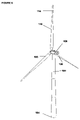
- FIG. 6 is a perspective view of a wind turbine installation in which the present invention is embodied.
- a wind power-generating device includes an electric generator housed in a turbine 100 , which is mounted atop a tall tower structure 102 anchored to the ground 104 .
- the turbine 100 is mounted on a structure 102 that is held stationary with reference to fluid flow, wind or water.
- the turbine is free to rotate in the horizontal plane such that it tends to remain in the path of prevailing wind current.
- the turbine has a rotor with variable pitch blades 106 , 108 , 110 , which rotate in response to wind current.
- Each of the blades has a blade base section referred to as a root blade attached to a rotor hub and a blade extension (for example 114 for blade 110 ) referred to as an extender blade that is variable in length to provide a variable diameter rotor.
- the rotor diameter is controlled to fully extend the rotor at low flow velocity and to retract the rotor as flow velocity increases such that the loads delivered by or exerted upon the rotor do not exceed set limits.
- the power-generating device is held by the tower structure in the path of the wind current such that the power-generating device is held in place horizontally in alignment with the wind current.
- An electric generator is driven by the turbine to produce electricity and is connected to power carrying cables inter-connecting the generator to other units and/or to a power grid.
- 6,726,439 B2 describes a wind or water flow energy converter comprising a wind or water flow actuated rotor assembly.
- the rotor comprises a plurality of blades, wherein the blades are variable in length to provide a variable diameter rotor.
- the rotor diameter is controlled to fully extend the rotor at low flow velocity and to retract the rotor as flow velocities increases such that the loads delivered by or exerted upon the rotor do not exceed set limits.
- FIG. 1 is a cut-away view of the servomotor controlled rack-and-pinion actuation mechanism of the present invention with the rotor fully extended.
- a rotor has a root blade 10 and an extender blade 12 attached to an extension bar 14 by bolts.
- Extension bar 14 is connected to a rack gear 16 .
- Servomotor 18 and pinion 20 on one side of rack gear 16 are anchored at the hub end of the root blade 10 mounted to the interior cavity of the root blade 10 .
- a second servomotor 19 and pinion 24 may be located on an opposite side of a rack gear 16 .
- the rack gear 16 engages the pinion gear 20 on a hub end thereof and the rack gear 16 is connected on the other end to the extension bar 14 .
- Conventional rack and pinion gears consist of a bar gear of rectangular cross section (the rack), having teeth on one side that mesh with teeth on a small gear (the pinion).
- the servomotor 18 drives pinion 20 such that it rotates about a fixed axis
- the rack 16 and hence the connected extender blade 12 will move in a straight path in one direction.
- the servomotor 19 drives pinion 24 such that it rotates about a fixed axis
- the rack 16 and hence the connected extender blade 12 will move in a straight path in the opposite direction.
- the two servomotors 18 , 19 drive their respective pinions in opposite directions, enabling the rotor extender blade 12 to be extended or retracted as the rack moves linearly.
- An optional friction brake is supplied to lock the rack when the extender blade is in a desired position.
- the brake is activated by a hydraulic system or other activation system. For safety, the brake is applied when not activated and is released when activated. Hence the brake is always in a fail-safe condition.
- FIG. 2 illustrates a cut-away view of the extendible rotor 12 within the main blade 10 shown in FIG. 1 .
- Bearings 26 are mounted on an inner portion of the extender blade 12 .
- the blade extension rides within a guide 28 .
- the bearings are mounted to the spars of the extender blade 10 .
- FIG. 3 shows a cross section view of the rotor blade taken along the view line A-A of FIG. 2 .
- Each root blade portion has spaced apart ribs defining the airfoil contour of the root blade and a lengthwise front spar 29 and rear spar 30 which are the main strength members of the root blade to which the ribs are attached.
- Each rib forms a leading edge 31 of the root blade and a tapered trailing edge 32 , which completes the airfoil contour of the root blade.
- the ribs are covered with a fiberglass skin 33 .
- the rotor extender blade 12 is housed within the root blade 10 .
- the rotor extender blade 12 has spaced apart ribs defining the airfoil contour of the rotor blade extension and lengthwise front and rear spars, which are the main strength members of the rotor blade extension.
- the bearings 26 allow the extender blade 12 to roll within a space between the front and rear spars 29 and 30 .
- the extender blade 12 is illustrated as mounted by bearings on the extender blade 12 and guided by a front rail 34 built into the front spar 29 and a rear rail 35 built into the rear spar 30 of the root blade 10 .
- FIG. 4 is a more detailed view of the servomotor, pinion and rack shown in FIG. 1 .
- Servomotor 18 and pinion 20 on one side of rack gear 16 are anchored at the hub end of the base section mounted to the interior cavity of the root blade 10 .
- a second servomotor 19 and pinion 24 may be located on an opposite side of a rack gear 16 .
- the rack gear 16 engages the pinion gear 20 on a hub end of rack gear 16 and the rack gear 16 is connected on the other end to the extender blade 12 by means of an extension bar 14 .
- a conventional rack and pinion gears consist of a bar gear of rectangular cross section (the rack), having teeth on one side that mesh with teeth on a small gear (the pinion).
- the rack 16 and hence the connected extender blade 12 will move in a straight path in one direction. If the servomotor 19 drives pinion 24 such that it rotates about a fixed axis, the rack 16 and hence the connected extender blade 12 will move in a straight path in the opposite direction. Thus the two servomotors drive their respective pinions in opposite directions, enabling the rotor extender blade 12 to be extended or retracted as the rack moves linearly.
- An optional friction brake 21 is supplied to lock the rack when the extender blade is in a desired position. For safety, the brake 21 is applied when not activated and is released when activated by a hydraulic system or other activation system. Hence the brake is always in a fail-safe condition.
- a second brake (not shown) may also be employed.
- the Turbine Control Unit 68 shown in FIG. 5 performs control functions in accordance with the methods described in U.S. Pat. No. 6,726,439. That is, a control method controls the rotor system to operate within four regions. A first of the regions being at velocities below cut-in, a second of the regions being over a range of intermediate velocities which yield varying power production, and a third of the regions being at higher velocities in which the turbines produce constant or slightly decreasing power in order to limit loads, and a fourth of the regions being at extremely high velocities in which the turbines cut-out.
- control method controls the rotor system to operate within a fifth region in which rotor diameter is varied by sending signals over bus 74 to servo 18 over signal line 15 and to servo 19 over signal line 17 to maintain operation within a specified loads regime.
- the specified load regime may be such that, in all wind or water flow velocities below a flow velocity required to reach rated power, the rotor diameter is extended to a maximum diameter permissible to remain within specified rotor load limits.
- the rotor load limits may be, for example, limitations on rotor thrust and/or shaft torque.
- To allow axial movement of the extendible rotor blade the two brakes must be deactivated by signals on deactivate brake 1 line 23 and deactivate brake 2 line 25 .
- FIG. 5 is a block diagram of a variable-speed wind turbine apparatus in accordance with the present invention.
- the basic components of the system are as follows. (1) A turbine drive train including a rotor hub-mounted pitch servo system 40 , blade rotor including root blade 42 and extender blade 44 , gearbox and a permanent magnet generator (PMG) 48 , (2) generator rectifier/inverter unit 50 ; (3) a control system to comprising a turbine control unit (TCU); generator control unit (GCU) 62 , (4) a pad-mount transformer 52 , and (5) SCADA interface 64 connecting the system to a utility grid.
- a turbine drive train including a rotor hub-mounted pitch servo system 40 , blade rotor including root blade 42 and extender blade 44 , gearbox and a permanent magnet generator (PMG) 48 , (2) generator rectifier/inverter unit 50 ; (3) a control system to comprising a turbine control unit (TCU); generator control unit (GCU) 62 , (4) a pad
- the turbine comprises one or more rotor blades 42 , 44 connected, via a rotor hub mounted pitch-angle servo, which is powered through slip rings via blade pitch signal bus 74 .
- the hub 40 is mechanically connected to a turbine main-shaft 46 , which transmits the turbine's torque to a gearbox 48 .
- the turbine shaft is coupled via gearbox 48 and some suitable coupling device to, in this example, a permanent magnet or wound field synchronous generator.
- the generator electrical output is connected to block 50 , which includes a rectifier, which converts the electrical power to DC voltage and current I (wind) on a DC bus.
- the DC bus is connected to wind turbine generator (WTG) inverter.
- WTG wind turbine generator
- the inverter regulates the DC current and by doing so, the generator torque is controlled.
- the inverter regulates this DC current by synchronizing to the grid and by supplying unity power factor current into the grid system.
- the control of the inverter (within block 50 ) is provided by a generator control unit (GCU) 62 .
- the GCU takes inputs such as grid voltage, DC bus voltage, grid current load power demand I (demand in) from the Supervisory Control and Data Acquisition (SCADA) interface 64 , and commands such as torque level from a Turbine Control unit (TCU) 60 .
- SCADA Supervisory Control and Data Acquisition
- PWM pulse-width-modulated
- the TCU 60 and GCU 62 work together in a multiple generator system to stage the generators, when the turbine is operating at less than full power rating.
- the controller brings each generator of the plurality of synchronous generators in the turbine online sequentially in the event of low energy conditions of the source of energy (wind, water, etc.) to improve system efficiency at low power.
- the controller may optionally alternate the sequence in which the controller shifts the order in which the generators are brought online such that each generator receives substantially similar utilization.
- the TCU 60 receives sensor information provided by sensor inputs 58 such as turbine speed, blade pitch angle, tower acceleration (vibration), nacelle acceleration (nacelle vibration), wind speed, wind direction, wind turbulence, nacelle position, AC line parameters, DC bus voltage, generator voltage, power output, and other fault related sensors.
- the TCU 60 has control of the principle actuators on the turbine; the generators via the GCU 62 , the pitch unit (PCU) 66 and the Blade Extension Control Unit (ECU) 68 .
- the TCU 60 performs a complicated, coordinated control function for both of these elements, and does so in a way, which maximizes the energy capture of the turbine while minimizing the machine's mechanical loads.
- the TCU 60 also controls a yaw system, which works to keep the turbine always pointed into the wind.
- the TCU 60 is also in communication with the turbine's SCADA system 64 in order to provide and receive sensor and status information.
- the Turbine Control Unit (TCU) and Generator Control Unit (GCU) command the proper generator torque required based on the rotor speed and power output of the turbine inverter system as well as providing any active damping requirements. Torque control is accomplished through inverter current commands generated by the TCU and GCU. In high winds the turbine remains at a constant average output power through a constant torque command from TCU and GCU and the TCU provides a varying pitch command to the hub mounted pitch servo system.
- control commands can be independent or can be a part of a State-Space Control logic.
- torque and speed are a subset of the turbine state space that include other parameters such as pitch rate, pitch acceleration and various turbine loads.
- the control system governs the variable rotor radius, the pitch of the rotor blades, and the rotational rate of said rotor.
- the TCU 60 determines a pitch angle for the blades by means of an algorithm or lookup tables.
- a blade pitch command 70 is sent from the TCU 60 to the Blade Pitch Control Unit (PCU) 66 which generates blade rotation drive signals D 1 , D 2 , D 3 , which pass over bus 74 to each of three servo motors that turn their respective blades.
- PCU Blade Pitch Control Unit
- the TCU 60 also determines the desired position of the extendable/retractable blade extensions 44 by means of an algorithm or lookup tables.
- An extension command is sent by the TCU 60 to the Blade Extension Control Unit (ECU) 68 which generates blade extension drive signals E 1 , E 2 , E 3 , which pass over bus 74 to each of three servo motors that extend/retract their respective blade extensions.
- ECU Blade Extension Control Unit
- the control system governs the variable rotor radius, the pitch of the rotor blades, and the rotational rate of the rotor, using one or more of the following sensor inputs:
- a turbine is mounted on a structure that is held stationary with reference to the fluid flow, on a wind tower or tethered under water.
- the turbine includes a rotor having a root blade connected to a rotor hub and an extender blade mounted within the root blade, the turbine being positioned on the structure such that the rotor is in alignment with fluid flow direction.
- the extender blade is moveable between a position at least partially retracted and an exposed position relative to the root blade.
- An adjusting device for the extender blade includes a servomotor-controlled rack and pinion actuation mechanism that converts rotation of the pinion by the servomotor into linear motion of the extender blade.
- a generator is connected to the turbine for generating electrical energy.
Abstract
Description
Claims (14)
Priority Applications (1)
| Application Number | Priority Date | Filing Date | Title |
|---|---|---|---|
| US11/084,640 US7581926B1 (en) | 2004-03-22 | 2005-03-18 | Servo-controlled extender mechanism for extendable rotor blades for power generating wind and ocean current turbines |
Applications Claiming Priority (2)
| Application Number | Priority Date | Filing Date | Title |
|---|---|---|---|
| US55550304P | 2004-03-22 | 2004-03-22 | |
| US11/084,640 US7581926B1 (en) | 2004-03-22 | 2005-03-18 | Servo-controlled extender mechanism for extendable rotor blades for power generating wind and ocean current turbines |
Publications (1)
| Publication Number | Publication Date |
|---|---|
| US7581926B1 true US7581926B1 (en) | 2009-09-01 |
Family
ID=41009143
Family Applications (1)
| Application Number | Title | Priority Date | Filing Date |
|---|---|---|---|
| US11/084,640 Expired - Fee Related US7581926B1 (en) | 2004-03-22 | 2005-03-18 | Servo-controlled extender mechanism for extendable rotor blades for power generating wind and ocean current turbines |
Country Status (1)
| Country | Link |
|---|---|
| US (1) | US7581926B1 (en) |
Cited By (32)
| Publication number | Priority date | Publication date | Assignee | Title |
|---|---|---|---|---|
| US20080317599A1 (en) * | 2007-06-21 | 2008-12-25 | Manuel Torres Martinez | Blade for a horizontal-axis wind generator |
| US20100086409A1 (en) * | 2008-10-08 | 2010-04-08 | David Anthony Whiley | Wind turbine rotor |
| US20100104437A1 (en) * | 2008-10-24 | 2010-04-29 | Caraballoso Esteban A | Retractable composite impeller assembly |
| US20100148506A1 (en) * | 2007-05-14 | 2010-06-17 | Repower Systems Ag | Rotor blade adjustment device for a wind turbine |
| US20100158687A1 (en) * | 2008-12-19 | 2010-06-24 | Frontier Wind, Llc | Control Modes for Extendable Rotor Blades |
| US20110097207A1 (en) * | 2009-10-26 | 2011-04-28 | Wu Chao-Cheng | Pressure relief device |
| US20110204634A1 (en) * | 2010-02-25 | 2011-08-25 | Skala James A | Synchronous Induced Wind Power Generation System |
| US20110204632A1 (en) * | 2010-02-25 | 2011-08-25 | Skala James A | Synchronous Induced Wind Power Generation System |
| JP2012180083A (en) * | 2011-02-28 | 2012-09-20 | Boeing Co:The | Disc rotor retraction system |
| US8508065B1 (en) | 2010-11-24 | 2013-08-13 | Chu B. Lee | Windmill generator system |
| US20130214532A1 (en) * | 2011-07-18 | 2013-08-22 | Sean Nean Hsu | Tunable Fluid Flow Generator |
| US8573937B2 (en) | 2008-11-21 | 2013-11-05 | Xzeres Corp. | System for providing dynamic pitch control in a wind turbine |
| US8672631B2 (en) | 2010-08-31 | 2014-03-18 | Hamilton Sundstrand Corporation | Articulated wind turbine blades |
| US20140109703A1 (en) * | 2011-01-05 | 2014-04-24 | General Dynamics Armament And Technical Products, Inc. | Loading machine for feeding a receiver |
| US20140271216A1 (en) * | 2013-03-15 | 2014-09-18 | George J. Syrovy | Horizontal axis wind or water turbine with forked or multi-blade upper segments |
| US20150260045A1 (en) * | 2012-10-10 | 2015-09-17 | Snecma | Propeller comprising a moveable dynamic scoop |
| CN105156266A (en) * | 2015-09-14 | 2015-12-16 | 华锐风电科技(集团)股份有限公司 | Wind generator set blade and wind generator set |
| US9297357B2 (en) | 2013-04-04 | 2016-03-29 | General Electric Company | Blade insert for a wind turbine rotor blade |
| US9500179B2 (en) | 2010-05-24 | 2016-11-22 | Vestas Wind Systems A/S | Segmented wind turbine blades with truss connection regions, and associated systems and methods |
| US9506452B2 (en) | 2013-08-28 | 2016-11-29 | General Electric Company | Method for installing a shear web insert within a segmented rotor blade assembly |
| EP2778398A3 (en) * | 2013-03-15 | 2018-03-07 | GE Infrastructure Technology, LLC | Failsafe deployment system for wind turbine blade air deflector |
| US20180163694A1 (en) * | 2016-12-12 | 2018-06-14 | Chin-Li Pai | Blade structure of water flow power generation system |
| RU2664890C2 (en) * | 2015-03-31 | 2018-08-23 | Марат Сайфетдинович Булатов | Wing windmill |
| US20190176634A1 (en) * | 2017-12-13 | 2019-06-13 | Hyundai Motor Company | Locking mechanism for vehicle |
| US20210324831A1 (en) * | 2018-08-01 | 2021-10-21 | Vestas Wind Systems A/S | Noise reduction in a wind turbine with hinged blades |
| US11319920B2 (en) * | 2019-03-08 | 2022-05-03 | Big Moon Power, Inc. | Systems and methods for hydro-based electric power generation |
| US11454216B2 (en) * | 2018-02-05 | 2022-09-27 | Mishra Dishant | Wind turbine system and method |
| US20220325693A1 (en) * | 2021-04-12 | 2022-10-13 | Lm Wind Power A/S | Extendable wind turbine blade |
| US20230053124A1 (en) * | 2020-01-08 | 2023-02-16 | Introfoc Ltd | Systems and Methods for Harnessing Energy from Wind |
| US20230106043A1 (en) * | 2021-10-04 | 2023-04-06 | General Electric Renovables Espana, S.L. | Devices and methods for vibration mitigation on wind turbines |
| US20230407840A1 (en) * | 2006-06-12 | 2023-12-21 | Energyield Llc | Rotatable Blade Apparatus With Individually Adjustable Blades |
| US11959456B2 (en) * | 2021-10-04 | 2024-04-16 | General Electric Renovables Espana, S.L. | Devices and methods for vibration mitigation on wind turbines |
Citations (17)
| Publication number | Priority date | Publication date | Assignee | Title |
|---|---|---|---|---|
| US1077187A (en) * | 1911-08-26 | 1913-10-28 | Joseph E Bissell | Propeller. |
| GB252461A (en) * | 1925-02-27 | 1926-05-27 | Kurt Bilau | Improvements in or relating to wind-driven prime movers |
| US3501248A (en) * | 1967-05-17 | 1970-03-17 | Friedrich W Brocker | Variable diameter propellers |
| US3606571A (en) * | 1968-03-08 | 1971-09-20 | Reginald T Wood | Stowed rotor |
| US3814351A (en) * | 1972-12-06 | 1974-06-04 | United Aircraft Corp | Coaxial rotor yaw control |
| US4180372A (en) * | 1977-03-02 | 1979-12-25 | Grumman Corporation | Wind rotor automatic air brake |
| US4453858A (en) * | 1980-07-30 | 1984-06-12 | Brissonneau & Lotz Marine | Safety device for marine platform |
| US4710101A (en) * | 1985-04-26 | 1987-12-01 | James Howden & Company Limited | Wind turbine |
| US4714388A (en) | 1986-10-14 | 1987-12-22 | Dayton Machine Tool Company | Dual pinion anti-backlash carriage drive for a machine tool |
| US5140856A (en) * | 1990-12-03 | 1992-08-25 | Dynamic Rotor Balancing, Inc. | In situ balancing of wind turbines |
| US5630705A (en) * | 1992-04-29 | 1997-05-20 | Eikelenboom; Pieter A. J. | Rotor construction for windmill |
| US6705421B2 (en) | 2002-05-31 | 2004-03-16 | Visteon Global Technologies, Inc. | Assisted steering system with out-of-phase driver and assist pinions |
| US6726439B2 (en) * | 2001-08-22 | 2004-04-27 | Clipper Windpower Technology, Inc. | Retractable rotor blades for power generating wind and ocean current turbines and means for operating below set rotor torque limits |
| US6902370B2 (en) * | 2002-06-04 | 2005-06-07 | Energy Unlimited, Inc. | Telescoping wind turbine blade |
| US6923622B1 (en) * | 2002-03-07 | 2005-08-02 | Clipper Windpower Technology, Inc. | Mechanism for extendable rotor blades for power generating wind and ocean current turbines and means for counter-balancing the extendable rotor blade |
| US7042110B2 (en) * | 2003-05-07 | 2006-05-09 | Clipper Windpower Technology, Inc. | Variable speed distributed drive train wind turbine system |
| US7071578B1 (en) * | 2002-01-10 | 2006-07-04 | Mitsubishi Heavy Industries, Ltd. | Wind turbine provided with a controller for adjusting active annular plane area and the operating method thereof |
-
2005
- 2005-03-18 US US11/084,640 patent/US7581926B1/en not_active Expired - Fee Related
Patent Citations (17)
| Publication number | Priority date | Publication date | Assignee | Title |
|---|---|---|---|---|
| US1077187A (en) * | 1911-08-26 | 1913-10-28 | Joseph E Bissell | Propeller. |
| GB252461A (en) * | 1925-02-27 | 1926-05-27 | Kurt Bilau | Improvements in or relating to wind-driven prime movers |
| US3501248A (en) * | 1967-05-17 | 1970-03-17 | Friedrich W Brocker | Variable diameter propellers |
| US3606571A (en) * | 1968-03-08 | 1971-09-20 | Reginald T Wood | Stowed rotor |
| US3814351A (en) * | 1972-12-06 | 1974-06-04 | United Aircraft Corp | Coaxial rotor yaw control |
| US4180372A (en) * | 1977-03-02 | 1979-12-25 | Grumman Corporation | Wind rotor automatic air brake |
| US4453858A (en) * | 1980-07-30 | 1984-06-12 | Brissonneau & Lotz Marine | Safety device for marine platform |
| US4710101A (en) * | 1985-04-26 | 1987-12-01 | James Howden & Company Limited | Wind turbine |
| US4714388A (en) | 1986-10-14 | 1987-12-22 | Dayton Machine Tool Company | Dual pinion anti-backlash carriage drive for a machine tool |
| US5140856A (en) * | 1990-12-03 | 1992-08-25 | Dynamic Rotor Balancing, Inc. | In situ balancing of wind turbines |
| US5630705A (en) * | 1992-04-29 | 1997-05-20 | Eikelenboom; Pieter A. J. | Rotor construction for windmill |
| US6726439B2 (en) * | 2001-08-22 | 2004-04-27 | Clipper Windpower Technology, Inc. | Retractable rotor blades for power generating wind and ocean current turbines and means for operating below set rotor torque limits |
| US7071578B1 (en) * | 2002-01-10 | 2006-07-04 | Mitsubishi Heavy Industries, Ltd. | Wind turbine provided with a controller for adjusting active annular plane area and the operating method thereof |
| US6923622B1 (en) * | 2002-03-07 | 2005-08-02 | Clipper Windpower Technology, Inc. | Mechanism for extendable rotor blades for power generating wind and ocean current turbines and means for counter-balancing the extendable rotor blade |
| US6705421B2 (en) | 2002-05-31 | 2004-03-16 | Visteon Global Technologies, Inc. | Assisted steering system with out-of-phase driver and assist pinions |
| US6902370B2 (en) * | 2002-06-04 | 2005-06-07 | Energy Unlimited, Inc. | Telescoping wind turbine blade |
| US7042110B2 (en) * | 2003-05-07 | 2006-05-09 | Clipper Windpower Technology, Inc. | Variable speed distributed drive train wind turbine system |
Cited By (45)
| Publication number | Priority date | Publication date | Assignee | Title |
|---|---|---|---|---|
| US20230407840A1 (en) * | 2006-06-12 | 2023-12-21 | Energyield Llc | Rotatable Blade Apparatus With Individually Adjustable Blades |
| US20100148506A1 (en) * | 2007-05-14 | 2010-06-17 | Repower Systems Ag | Rotor blade adjustment device for a wind turbine |
| US8344532B2 (en) * | 2007-05-14 | 2013-01-01 | Repower Systems Ag | Rotor blade adjustment device for a wind turbine |
| US20080317599A1 (en) * | 2007-06-21 | 2008-12-25 | Manuel Torres Martinez | Blade for a horizontal-axis wind generator |
| US20100086409A1 (en) * | 2008-10-08 | 2010-04-08 | David Anthony Whiley | Wind turbine rotor |
| US8262360B2 (en) * | 2008-10-08 | 2012-09-11 | Blade Dynamics Limited | Wind turbine rotor |
| US20100104437A1 (en) * | 2008-10-24 | 2010-04-29 | Caraballoso Esteban A | Retractable composite impeller assembly |
| US8573937B2 (en) | 2008-11-21 | 2013-11-05 | Xzeres Corp. | System for providing dynamic pitch control in a wind turbine |
| US20100158687A1 (en) * | 2008-12-19 | 2010-06-24 | Frontier Wind, Llc | Control Modes for Extendable Rotor Blades |
| US8128361B2 (en) * | 2008-12-19 | 2012-03-06 | Frontier Wind, Llc | Control modes for extendable rotor blades |
| US8425190B2 (en) * | 2009-10-26 | 2013-04-23 | United Ship Design And Development Center | Pressure relief device |
| US20110097207A1 (en) * | 2009-10-26 | 2011-04-28 | Wu Chao-Cheng | Pressure relief device |
| US20110204634A1 (en) * | 2010-02-25 | 2011-08-25 | Skala James A | Synchronous Induced Wind Power Generation System |
| US20110204632A1 (en) * | 2010-02-25 | 2011-08-25 | Skala James A | Synchronous Induced Wind Power Generation System |
| US9500179B2 (en) | 2010-05-24 | 2016-11-22 | Vestas Wind Systems A/S | Segmented wind turbine blades with truss connection regions, and associated systems and methods |
| US8672631B2 (en) | 2010-08-31 | 2014-03-18 | Hamilton Sundstrand Corporation | Articulated wind turbine blades |
| US8508065B1 (en) | 2010-11-24 | 2013-08-13 | Chu B. Lee | Windmill generator system |
| US9091333B2 (en) * | 2011-01-05 | 2015-07-28 | General Dynamics—OTS, Inc. | Loading machine for feeding a receiver |
| US20140109703A1 (en) * | 2011-01-05 | 2014-04-24 | General Dynamics Armament And Technical Products, Inc. | Loading machine for feeding a receiver |
| JP2012180083A (en) * | 2011-02-28 | 2012-09-20 | Boeing Co:The | Disc rotor retraction system |
| US9410527B2 (en) * | 2011-07-18 | 2016-08-09 | Sean N. Hsu | Tunable apparatus for generating energy from a fluid flow induced movement of a surface structure relative to a frame with at least one adjustable frame portion |
| US20130214532A1 (en) * | 2011-07-18 | 2013-08-22 | Sean Nean Hsu | Tunable Fluid Flow Generator |
| US20150260045A1 (en) * | 2012-10-10 | 2015-09-17 | Snecma | Propeller comprising a moveable dynamic scoop |
| US9790794B2 (en) * | 2012-10-10 | 2017-10-17 | Snecma | Propeller comprising a moveable dynamic scoop |
| US20140271216A1 (en) * | 2013-03-15 | 2014-09-18 | George J. Syrovy | Horizontal axis wind or water turbine with forked or multi-blade upper segments |
| EP2778398A3 (en) * | 2013-03-15 | 2018-03-07 | GE Infrastructure Technology, LLC | Failsafe deployment system for wind turbine blade air deflector |
| US9989033B2 (en) * | 2013-03-15 | 2018-06-05 | George J. Syrovy | Horizontal axis wind or water turbine with forked or multi-blade upper segments |
| US9297357B2 (en) | 2013-04-04 | 2016-03-29 | General Electric Company | Blade insert for a wind turbine rotor blade |
| US9506452B2 (en) | 2013-08-28 | 2016-11-29 | General Electric Company | Method for installing a shear web insert within a segmented rotor blade assembly |
| RU2664890C2 (en) * | 2015-03-31 | 2018-08-23 | Марат Сайфетдинович Булатов | Wing windmill |
| CN105156266A (en) * | 2015-09-14 | 2015-12-16 | 华锐风电科技(集团)股份有限公司 | Wind generator set blade and wind generator set |
| US20180163694A1 (en) * | 2016-12-12 | 2018-06-14 | Chin-Li Pai | Blade structure of water flow power generation system |
| US20190176634A1 (en) * | 2017-12-13 | 2019-06-13 | Hyundai Motor Company | Locking mechanism for vehicle |
| US10744893B2 (en) * | 2017-12-13 | 2020-08-18 | Hyundai Motor Company | Locking mechanism for vehicle |
| US11454216B2 (en) * | 2018-02-05 | 2022-09-27 | Mishra Dishant | Wind turbine system and method |
| US20210324831A1 (en) * | 2018-08-01 | 2021-10-21 | Vestas Wind Systems A/S | Noise reduction in a wind turbine with hinged blades |
| US20220228550A1 (en) * | 2019-03-08 | 2022-07-21 | Big Moon Power, Inc. | Systems and methods for hydro-based electric power generation |
| US11319920B2 (en) * | 2019-03-08 | 2022-05-03 | Big Moon Power, Inc. | Systems and methods for hydro-based electric power generation |
| US11835025B2 (en) * | 2019-03-08 | 2023-12-05 | Big Moon Power, Inc. | Systems and methods for hydro-based electric power generation |
| US20230053124A1 (en) * | 2020-01-08 | 2023-02-16 | Introfoc Ltd | Systems and Methods for Harnessing Energy from Wind |
| US20220325693A1 (en) * | 2021-04-12 | 2022-10-13 | Lm Wind Power A/S | Extendable wind turbine blade |
| EP4074959A1 (en) * | 2021-04-12 | 2022-10-19 | LM Wind Power A/S | Extendable wind turbine blade |
| US11885293B2 (en) * | 2021-04-12 | 2024-01-30 | Lm Wind Power A/S | Extendable wind turbine blade |
| US20230106043A1 (en) * | 2021-10-04 | 2023-04-06 | General Electric Renovables Espana, S.L. | Devices and methods for vibration mitigation on wind turbines |
| US11959456B2 (en) * | 2021-10-04 | 2024-04-16 | General Electric Renovables Espana, S.L. | Devices and methods for vibration mitigation on wind turbines |
Similar Documents
| Publication | Publication Date | Title |
|---|---|---|
| US7581926B1 (en) | Servo-controlled extender mechanism for extendable rotor blades for power generating wind and ocean current turbines | |
| US7582977B1 (en) | Extendable rotor blades for power generating wind and ocean current turbines within a module mounted atop a main blade | |
| AU2007278980B2 (en) | Retractable rotor blade structure | |
| US6923622B1 (en) | Mechanism for extendable rotor blades for power generating wind and ocean current turbines and means for counter-balancing the extendable rotor blade | |
| US6726439B2 (en) | Retractable rotor blades for power generating wind and ocean current turbines and means for operating below set rotor torque limits | |
| EP2252791B1 (en) | Retractable blade structure with a split trailing edge | |
| US9587630B2 (en) | Rotor kite wind energy system and more | |
| EP1888917B1 (en) | Vertical axis wind turbine having an overspeeding regulator controlling multiple aerodynamic elements | |
| EP0449979A1 (en) | Vertical axis sail bladed wind turbine | |
| US10053216B2 (en) | Tethered wing system for wind energy use | |
| US8053919B1 (en) | Wind turbine power generator | |
| CN108457795B (en) | Wind wheel of wind driven generator with automatic pitch control and disabling protection | |
| EP3622173B1 (en) | A wind energy park comprising airborne wind energy systems | |
| AU2014201460A1 (en) | Failsafe system for load compensating device | |
| US10435145B1 (en) | Vehicle with tension wing assembly | |
| US11021243B1 (en) | Tension airfoil assembly and implementation for power generation and aviation | |
| EP3622172B1 (en) | A wind installation comprising a wind turbine and an airborne wind energy system | |
| CN210714927U (en) | Novel adjustment mechanism of umbrella-shaped wind turbine | |
| CN210948991U (en) | Equipment for generating electricity by large kite windmill | |
| WO2021071469A1 (en) | Tension airfoil assembly and implementation for power generation and aviation | |
| CN103233855A (en) | Mixed-pitch technology of wind power impeller | |
| CN201246276Y (en) | Umbrella type wind sail blade wind motor | |
| WO2018206064A1 (en) | A wind turbine and an airborne wind energy system sharing yaw system | |
| AU2012244194A1 (en) | Vertical Axis Wind Turbines |
Legal Events
| Date | Code | Title | Description |
|---|---|---|---|
| AS | Assignment |
Owner name: CLIPPER WINDPOWER TECHNOLOGY, INC., CALIFORNIA Free format text: ASSIGNMENT OF ASSIGNORS INTEREST;ASSIGNORS:DEHLSEN, JAMES G.P.;CLIPPER WINDPOWER, INC.;REEL/FRAME:022471/0901 Effective date: 20050331 Owner name: CLIPPER WINDPOWER TECHNOLOGY, INC., CALIFORNIA Free format text: ASSIGNMENT OF ASSIGNORS INTEREST;ASSIGNOR:MIKHAIL, AMIR S.;REEL/FRAME:022471/0829 Effective date: 20090323 |
|
| AS | Assignment |
Owner name: CLIPPER WINDPOWER, INC.,CALIFORNIA Free format text: MERGER;ASSIGNOR:CLIPPER WINDPOWER TECHNOLOGY, INC.;REEL/FRAME:024244/0001 Effective date: 20091228 Owner name: CLIPPER WINDPOWER, INC., CALIFORNIA Free format text: MERGER;ASSIGNOR:CLIPPER WINDPOWER TECHNOLOGY, INC.;REEL/FRAME:024244/0001 Effective date: 20091228 |
|
| AS | Assignment |
Owner name: UNITED TECHNOLOGIES CORPORATION, CONNECTICUT Free format text: ASSIGNMENT OF ASSIGNORS INTEREST;ASSIGNOR:CLIPPER WINDPOWER, INC.;REEL/FRAME:024958/0213 Effective date: 20100819 |
|
| AS | Assignment |
Owner name: UNITED TECHNOLOGIES CORPORATION, CONNECTICUT Free format text: SECURITY AGREEMENT;ASSIGNOR:CLIPPER WINDPOWER, INC.;REEL/FRAME:025642/0623 Effective date: 20101017 |
|
| AS | Assignment |
Owner name: CLIPPER WINDPOWER, LLC, CALIFORNIA Free format text: CHANGE OF NAME;ASSIGNOR:CLIPPER WINDPOWER, INC.;REEL/FRAME:027136/0891 Effective date: 20110701 |
|
| FPAY | Fee payment |
Year of fee payment: 4 |
|
| REMI | Maintenance fee reminder mailed | ||
| LAPS | Lapse for failure to pay maintenance fees |
Free format text: PATENT EXPIRED FOR FAILURE TO PAY MAINTENANCE FEES (ORIGINAL EVENT CODE: EXP.) |
|
| STCH | Information on status: patent discontinuation |
Free format text: PATENT EXPIRED DUE TO NONPAYMENT OF MAINTENANCE FEES UNDER 37 CFR 1.362 |
|
| FP | Lapsed due to failure to pay maintenance fee |
Effective date: 20170901 |