US7384609B2 - Pre-converter device for cleaning exhaust gas for an internal combustion engine - Google Patents
Pre-converter device for cleaning exhaust gas for an internal combustion engine Download PDFInfo
- Publication number
- US7384609B2 US7384609B2 US10/766,469 US76646904A US7384609B2 US 7384609 B2 US7384609 B2 US 7384609B2 US 76646904 A US76646904 A US 76646904A US 7384609 B2 US7384609 B2 US 7384609B2
- Authority
- US
- United States
- Prior art keywords
- sleeve
- converter device
- catalytic converter
- converter
- depression
- Prior art date
- Legal status (The legal status is an assumption and is not a legal conclusion. Google has not performed a legal analysis and makes no representation as to the accuracy of the status listed.)
- Expired - Fee Related, expires
Links
Images


Classifications
-
- B—PERFORMING OPERATIONS; TRANSPORTING
- B01—PHYSICAL OR CHEMICAL PROCESSES OR APPARATUS IN GENERAL
- B01D—SEPARATION
- B01D53/00—Separation of gases or vapours; Recovering vapours of volatile solvents from gases; Chemical or biological purification of waste gases, e.g. engine exhaust gases, smoke, fumes, flue gases, aerosols
- B01D53/34—Chemical or biological purification of waste gases
- B01D53/92—Chemical or biological purification of waste gases of engine exhaust gases
- B01D53/94—Chemical or biological purification of waste gases of engine exhaust gases by catalytic processes
-
- F—MECHANICAL ENGINEERING; LIGHTING; HEATING; WEAPONS; BLASTING
- F01—MACHINES OR ENGINES IN GENERAL; ENGINE PLANTS IN GENERAL; STEAM ENGINES
- F01N—GAS-FLOW SILENCERS OR EXHAUST APPARATUS FOR MACHINES OR ENGINES IN GENERAL; GAS-FLOW SILENCERS OR EXHAUST APPARATUS FOR INTERNAL COMBUSTION ENGINES
- F01N3/00—Exhaust or silencing apparatus having means for purifying, rendering innocuous, or otherwise treating exhaust
- F01N3/08—Exhaust or silencing apparatus having means for purifying, rendering innocuous, or otherwise treating exhaust for rendering innocuous
- F01N3/10—Exhaust or silencing apparatus having means for purifying, rendering innocuous, or otherwise treating exhaust for rendering innocuous by thermal or catalytic conversion of noxious components of exhaust
- F01N3/24—Exhaust or silencing apparatus having means for purifying, rendering innocuous, or otherwise treating exhaust for rendering innocuous by thermal or catalytic conversion of noxious components of exhaust characterised by constructional aspects of converting apparatus
- F01N3/28—Construction of catalytic reactors
- F01N3/2803—Construction of catalytic reactors characterised by structure, by material or by manufacturing of catalyst support
- F01N3/2807—Metal other than sintered metal
- F01N3/281—Metallic honeycomb monoliths made of stacked or rolled sheets, foils or plates
- F01N3/2821—Metallic honeycomb monoliths made of stacked or rolled sheets, foils or plates the support being provided with means to enhance the mixing process inside the converter, e.g. sheets, plates or foils with protrusions or projections to create turbulence
Definitions
- the present invention relates to a preliminary catalytic converter (“pre-converter”) device for cleaning exhaust gas, that contains hydrocarbons, which are emitted from an internal combustion engine.
- the pre-converter device has a perforated sleeve that is coated with a catalytic material to form an active surface.
- the area of the active surface increases as the distances from the pre-converter inlet increases.
- the pre-converter device is configured such that the active surface area on the pre-converter device increases as the temperature of the exhaust gases within the pre-converter device increases and the gas expands.
- the typical operation of internal combustion engines creates exhaust gases.
- the pollutant content of these exhaust gases must meet certain legally prescribed requirements. The content is usually determined during a cycle of operations including a cold start and idling operations.
- a catalytic converter is often used to cleanse the exhaust gas. These requirements cannot be met unless the catalytic converter can become quickly operational (i.e., rapidly heated).
- a catalytic converter is arranged in the exhaust manifold directly following the cylinder. This arrangement is helpful during cold starting because the catalytic converter is rapidly heated. This location of the converter, however, impairs the functional performance of the exhaust system because of the amount of space occupied by the converter.
- the reduction in performance of the exhaust system has a direct impact on engine performance including a deterioration of the power, a reduction in the torque delivered, and an increase in fuel consumption. Furthermore, the close proximity of the converter to the engine cylinders can cause undesired reactions on the cylinder.
- German Patent No. DE 10002024 C1 discloses catalytic device that is positioned between a first and a second section of the reactor.
- the catalytic device includes a boundary wall containing a catalytic material in the form of a foam or woven material that separates the two sections. Gases are directed from the first section into the second section through catalytic device.
- DE 100002024 discloses various configurations of the catalytic device including a conical tapered shape device having an enlarged end adjacent the first section and a reduced end adjacent the second section, a cylindrical shaped device having a plurality of channels extending along the axis of the device, and a cylindrical shaped device having a wavy exterior having portions with reduced diameter. These devices have been found to be inefficient and inadequate in treating the gas. In particular, these devices do not account for the expansion of the exhaust gas as it is heated while passing through the catalyst.
- Japanese Patent Nos. 5-86843 and 10-325315 disclose that it is known to provide a main catalytic converter, which is preceded by a preliminary catalytic converter.
- the provision of the pre-converter permits the main converter to be located a greater distance from the exhaust port. As such, the impact on engine performance is reduced.
- the pre-converter is used to clean exhaust gas and increase the temperature of the exhaust gases.
- the pre-converter ensures that the exhaust gas is at a proper temperature to activate the main converter and of a proper composition.
- Use of a pre-converter reduces the quantity of unburned hydrocarbons normally found in the exhaust gases emitted by an internal combustion engine.
- It is desirable to locate the pre-converter is disposed as close as possible to the cylinder of the internal combustion engine so that the high temperatures occurring adjacent to the cylinder will cause the pre-converter to be become quickly operational. Locating the pre-converter in too close a proximity to the cylinder will produce the above-described reduction in engine performance.
- U.S. Pat. No. 5,014,510 to Laimböck discloses a pre-converter positioned in an exhaust system adjacent the exhaust port of the engine.
- the location of this pre-converter suffers from many of the above-described drawbacks including an adverse impact on engine performance.
- the pre-converter extends across the entire cross-section of the exhaust system, which adversely impacts the flow dynamics of the exhaust gases within the exhaust system and performance.
- European Patent Application No. 411,561 discloses a pre-converter positioned in close proximity to the exhaust port of the engine. The location of this pre-converter adversely impacts engine performance.
- the pre-converter is positioned around the inner circumference of the exhaust system. As such, all of the exhaust gases from the cylinder do not flow through the pre-converter.
- a catalytic converter device for cleansing exhaust gas emitted from an internal combustion engine. While the catalytic converter device is preferably a pre-converter, the catalytic device can be a primary or main catalytic converter device as well.
- the converter device includes an elongated body having a longitudinal axis. An inlet area is located at one end of the elongated body. The exhaust gas from the internal combustion engine enters the elongated body in the inlet area.
- a sleeve extends from the inlet area.
- the sleeve has a catalytic material formed thereon.
- the sleeve has an active surface for reacting with the exhaust gas. The size of the active surface increases as a distance from the inlet area increases, whereby provides a greater surface for reaction with the exhaust gas to improve the conversion of the unburned hydrocarbons and pollutants.
- the sleeve has a plurality of openings formed therein to permit the exhaust gas to flow there through.
- the plurality of openings extend across the active surface.
- the sleeve can include at least one depression formed therein, which increases the amount of active surface area within the pre-converter for reacting with the unburned hydrocarbons and pollutants.
- the depression(s) can extend substantially parallel to the longitudinal axis of the body.
- the sleeve without a depression has a first internal cross section.
- the sleeve having the at least one depression has a second internal cross section.
- the second internal cross section is smaller than said first internal cross section.
- the second internal cross section changes as the distance from the inlet area increases.
- Each depression has a depth. In accordance with embodiments of the present invention, the depth of the depression can increase as the distance from the inlet area increases.
- an exhaust system for an internal combustion engine includes a flow path for exhaust gas emitted from the internal combustion engine.
- a primary catalytic converter device for cleansing the exhaust gas is arranged in the flow path.
- a preliminary catalytic converter device for cleansing the exhaust gas is also arranged in the flow path. The preliminary catalytic converter is upstream from the primary catalytic converter such that the exhaust gas emitted from the internal combustion engine travels through the preliminary catalytic converter device before traveling to the primary catalytic converter device.
- the preliminary converter device can include an elongated body having a longitudinal axis.
- An inlet area is located at one end of the elongated body.
- the exhaust gas from the internal combustion engine enters the elongated body in the inlet area.
- a sleeve extends from the inlet area.
- the sleeve has a catalytic material formed thereon.
- the sleeve has an active surface for reacting with the exhaust gas. The size of the active surface increases as a distance from the inlet area increases, whereby provides a greater surface for reaction with the exhaust gas to improve the conversion of the unburned hydrocarbons and pollutants.
- the exhaust system can further include a muffler. At least a portion of the preliminary converter device is arranged at least partially within the muffler.
- an internal cross-sectional area of the sleeve in at least one plane that is perpendicular to the longitudinal axis is at least about 5% smaller than an area of a circle having a perimeter equal to a perimeter of the active surface at the at least one plane.
- the circle may have a diameter that is larger than a width of the sleeve.
- the perimeter of the active surface may be non-circular at a longitudinal position where the perimeter increases as the sleeve extends away from the inlet area.
- FIG. 1 is a right side schematic view of a pre-converter according to an embodiment of the present invention
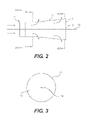
- FIG. 2 is a schematic diagram illustrating the flow of exhaust gas within the pre-converter of FIG. 1 ;
- FIG. 3 is a schematic representation of the cross section of the pre-converter along section line 3 - 3 in FIG. 2 ;
- FIG. 4 is a schematic representation of the cross section of the pre-converter along section line 3 - 3 in FIG. 2 ;
- FIG. 5 is a schematic representation of the cross section of the pre-converter along section line 3 - 3 in FIG. 2 ;
- FIG. 6 is a schematic view of an exhaust system employing a pre-converter in accordance with an embodiment of the present invention.
- a pre-converter 10 according to an embodiment of the present invention is illustrated in FIG. 1 .
- the pre-converter 10 is adapted to be incorporated into an exhaust system 20 for an internal combustion engine.
- the internal combustion engine can be either a two-stroke engine or a four-stroke engine.
- the engine can have one or more cylinders. It is contemplated that the internal combustion engine containing the pre-converter 10 can be used to supply power to a snowmobile, a personal watercraft, a motorcycle, a three-wheeled vehicle, a go-kart, an all-terrain vehicle, or an outboard engine for use on a boat.
- the pre-converter 10 has an elongated body, as shown in FIGS. 1 , 2 and 6 having an inlet area 11 located on one end. Exhaust gases from the engine cylinders are introduced into the pre-converter 10 through the inlet area 11 .
- the inlet area 11 preferably has a solid wall 12 such that is can be connected to the exhaust system 20 to prevent leakage of exhaust gas.
- the inlet area 11 is formed from metal, which can be a high alloy steel. As shown in FIG. 3 , the inlet area 11 has a generally circular cross section having a central passageway 13 extending there through substantially parallel to the longitudinal axis 14 .
- the central passageway 13 extends through the sleeve 15 , as shown in FIGS. 1 , 2 , and 4 - 6 .
- the sleeve 15 preferably has a plurality of openings 16 formed therein which substantially cover the sleeve 15 , as shown in FIG. 1 .
- the openings 16 permit the exhaust gases to flow there through.
- the wall forming the sleeve 15 and the openings 16 together form the active surface 17 of the pre-converter 10 . The conversion of the unburned hydrocarbons and the pollutants occurs on the active surface 17 .
- the perforated sleeve 15 is preferably formed from metal.
- the sleeve 15 can be formed from perforated sheet metal.
- the sleeve 15 can also be formed from a woven metal material, wherein the openings 16 are formed by the spaces between the metal threads, which form the material.
- the perforated sleeve 15 is coated with a catalyst material.
- the downstream end of the perforated sleeve 15 can be closed off by a suitable plate or cover 18 , as shown in FIGS. 2 and 6 .
- the provision of the cover 18 causes the exhaust gases to exit the perforated sleeve 15 through the openings 16 .
- the cover 18 can be omitted, which would result in a decrease in the overall performance of the pre-converter 10 .
- the exhaust gas is fed into the pre-converter 10 through the inlet area 11 whereby it is fed through the central passageway 13 into the sleeve 15 .
- the gas exits the sleeve 15 through the plurality of openings 16 .
- the flow of exhaust gas is illustrated by arrows in FIGS. 2 and 6 .
- the exhaust gas and more particularly the unburned hydrocarbons and/or other pollutants in the exhaust gas come into contact with the catalytic material coating the surfaces of the sleeve 15 .
- the hydrocarbons and pollutants undergo catalytic conversion and the exhaust gas is cleaned.
- the exhaust gas is then fed to the primary or main converter for further cleansing.
- the pre-converter 10 is preferably included as part of an exhaust system for an internal combustion engine.
- One possible exhaust system 20 is illustrated in FIG. 6 .
- the exhaust system 20 includes a muffler 21 .
- the muffler 21 can include a plurality of muffler chambers 22 and 23 that are separated by at least one partition 24 .
- a primary or main catalytic converter 25 is located within the muffler 21 .
- the converter 25 can be a conventional converter such as, for example, a converter having a honeycomb construction.
- the converter 25 can be located in one of the muffler chambers 22 and 23 .
- the converter 25 can also be located in the area between the chambers 22 and 23 in an opening formed in one of the partitions 24 , as shown in FIG. 6 .
- the exhaust gas enters the muffler 21 through a suitable supply pipe 26 , which is connected to the inlet area 11 of the pre-converter 10 .
- the exhaust gas passes through pre-converter 10 along the central passageway 13 .
- the exhaust gas passes through the openings 16 in the sleeve 15 into the first chamber 22 .
- the exhaust gas then travels through the primary converter 25 into the second chamber 23 .
- the treated exhaust gas then exits the muffler 21 through an opening 27 .
- Arranging the pre-converter 10 within the muffler 21 makes it possible to design an exhaust system with a simple design that also saves space. Locating the pre-converter 10 in the rear end of the muffler can reduce the temperature load in the area of the exhaust turbine or the front muffler.
- the pre-converter 10 and in particular, the shape of the perforated sleeve 15 will now be described in greater detail.
- the temperature of the exhaust gas within the pre-converter 10 increases within the pre-converter 10 in response to the exhaust gas and in particular the unburned hydrocarbons and pollutants reacting with the catalytic material on the active surface 17 (i.e., the temperature of the gas increases as the distance from the inlet area 11 increases). Given this phenomena, it is desirable to provide sufficient space within the pre-converter 10 to let the exhaust gas expand and penetrate the catalytic material on the active surface 17 . This can be accomplished by providing the perforated sleeve 15 with a generally conical shape that increases as the distance from the inlet area 11 increases, as shown in FIGS.
- the perforated sleeve 15 includes at least one depression or indentation 19 .
- the depth of the depression 19 can increase as the distance from the inlet area 11 increases.
- the provision of the depression(s) 19 increases the specific surface area of the active surface 17 of the pre-converter 10 .
- the central passageway 13 through which the exhaust gas flows has a generally circular cross-section in the inlet area 11 .
- the geometry of the central passageway 13 changes, as shown in FIGS. 4 and 5 .
- the depth of the depression(s) 19 also increases.
- the perforated sleeve 15 has an outer periphery 30 , which increases along the axis 14 in the direction of flow, as shown in FIGS. 4 and 5 .
- the cross-section of the perforated sleeve 15 containing depression(s) 19 is significantly smaller than the outer periphery 30 .
- the central passageway 13 has a comparatively smaller cross-sectional area.
- the at least one depression 19 is oriented essentially along the axis 14 .
- This arrangement of depressions ensures that as the specific surface grows larger, the internal cross section area of the pre-converter, which is to say the surface that is defined by the perforated outer casing of the pre-converter, grows smaller.
- the depressions 19 can be formed by compressing the sleeve 15 at desired locations. Thus, it is possible to achieve a sleeve 15 having a particularly stable shape that can withstand the temperature-induced expansion of the exhaust gases.
- one or more depressions 19 can be provided in the sleeve 15 .
- the depressions 19 extend in a direction substantially parallel to the axis 14 .
- the depressions 19 can being arranged at regular or irregular intervals around the sleeve 15 . As discussed above, the depth of the depressions 19 increases along the axis 14 . When a single depression 19 is provided, its depth and width may be greater than the depth and width of the depression when a plurality are present in order to provide the desired increase in area of the active surface 17 .
- a cross-sectional shape of the sleeve 15 also varies from a rounded shape at the inlet 11 to a clover-leaf like or bulbous shape at the downstream end of the sleeve 15 .
- the active surface 17 has a perimeter in a plane that is perpendicular to the longitudinal axis 14 .
- An internal cross-sectional area of the sleeve 15 is smaller than an area of a circle 30 having an equally long perimeter (i.e., the cross-section of the sleeve 15 is non-circular).
- the internal cross-sectional area of the sleeve 15 at the intermediate and downstream portions of the sleeve is preferably at least about 5% smaller than the area of the circle 30 , is more preferably at least about 10% smaller than the area of the circle 30 , is even more preferably at least about 20% smaller than the area of the circle 30 , is even more preferably at least about 30% smaller than the area of the circle 30 , and is even more preferably at least about 50% smaller than the area of the circle 30 .
- the circle 30 has a diameter that is larger than a width of the sleeve 15 .
- the pre-converter 10 has been described for use in the muffler 20 , it is contemplated that the pre-converter 10 can be placed in variation locations within the exhaust system provided the pre-converter 10 is positioned upstream from the main or primary converter. Variations in the shape of the pre-converter 10 are contemplated provided the surface area of the active surface 17 increases as the distance from the inlet area 11 increases. It is further contemplated that the pre-converter 10 described herein can be used as a primary or main catalytic converter device. The principles of the present invention are intended to encompass any and all changes, alterations and/or substitutions within the spirit and scope of the following claims.
Abstract
Description
Claims (15)
Priority Applications (1)
| Application Number | Priority Date | Filing Date | Title |
|---|---|---|---|
| US10/766,469 US7384609B2 (en) | 2003-01-29 | 2004-01-29 | Pre-converter device for cleaning exhaust gas for an internal combustion engine |
Applications Claiming Priority (2)
| Application Number | Priority Date | Filing Date | Title |
|---|---|---|---|
| US44318603P | 2003-01-29 | 2003-01-29 | |
| US10/766,469 US7384609B2 (en) | 2003-01-29 | 2004-01-29 | Pre-converter device for cleaning exhaust gas for an internal combustion engine |
Publications (2)
| Publication Number | Publication Date |
|---|---|
| US20040187485A1 US20040187485A1 (en) | 2004-09-30 |
| US7384609B2 true US7384609B2 (en) | 2008-06-10 |
Family
ID=32772056
Family Applications (1)
| Application Number | Title | Priority Date | Filing Date |
|---|---|---|---|
| US10/766,469 Expired - Fee Related US7384609B2 (en) | 2003-01-29 | 2004-01-29 | Pre-converter device for cleaning exhaust gas for an internal combustion engine |
Country Status (2)
| Country | Link |
|---|---|
| US (1) | US7384609B2 (en) |
| CA (1) | CA2453835A1 (en) |
Cited By (4)
| Publication number | Priority date | Publication date | Assignee | Title |
|---|---|---|---|---|
| US20090000304A1 (en) * | 2007-06-28 | 2009-01-01 | Honeywell International, Inc. | Integrated support and mixer for turbo machinery |
| US20090272106A1 (en) * | 2008-05-05 | 2009-11-05 | J. Eberspaecher Gmbh & Co. Kg | Exhaust gas treatment unit |
| US20100018191A1 (en) * | 2008-07-23 | 2010-01-28 | Gerald Peter Jackson | Catalytic smog reduction |
| US9323299B2 (en) | 2012-08-27 | 2016-04-26 | Green Light Industries, Inc. | Multiple power source unit |
Citations (15)
| Publication number | Priority date | Publication date | Assignee | Title |
|---|---|---|---|---|
| US4632216A (en) * | 1984-06-27 | 1986-12-30 | Donaldson Company, Inc. | Muffler apparatus and method for making same |
| GB2220150A (en) | 1988-07-08 | 1990-01-04 | Piaggio & C Spa | Exhaust system with catalytic converter for two-stroke engines |
| EP0411561A1 (en) | 1989-08-02 | 1991-02-06 | Aprilia S.P.A. | Catalytic muffler structure for engines |
| US5012642A (en) | 1989-06-01 | 1991-05-07 | Laimboeck Franz | Exhaust system for two-stroke cycle internal combustion engines |
| US5014510A (en) | 1989-06-01 | 1991-05-14 | Laimboeck Franz | Exhaust system, particularly for two-stroke cycle internal combustion engines |
| US5110560A (en) * | 1987-11-23 | 1992-05-05 | United Technologies Corporation | Convoluted diffuser |
| JPH0586843A (en) | 1991-09-26 | 1993-04-06 | Suzuki Motor Corp | Exhaust gas purifying device for motorcycle |
| JPH08326528A (en) | 1995-06-02 | 1996-12-10 | Honda Motor Co Ltd | Exhaust pipe provided with exhaust emission control device |
| US5828013A (en) * | 1992-06-02 | 1998-10-27 | Donaldson Company, Inc. | Muffler with catalytic converter arrangement; and method |
| JPH10325315A (en) | 1997-05-27 | 1998-12-08 | Suzuki Motor Corp | Exhaust emission control device for internal combustion engine |
| US5934073A (en) * | 1997-05-21 | 1999-08-10 | Degussa Aktiengesellschaft | Auxiliary heating for motor vehicles with internal combustion engines |
| DE10002024C1 (en) | 2000-01-19 | 2001-06-07 | Xcellsis Gmbh | Apparatus for treating a medium in a fuel cell system comprises a reactor with a catalyst-containing region between a first partial chamber of the reactor and a second partial chamber of the reactor |
| US6604604B1 (en) * | 2000-09-20 | 2003-08-12 | Fleetguard, Inc. | Catalytic muffler and method |
| US6689327B1 (en) * | 1995-08-16 | 2004-02-10 | Emitec Gesellschaft Fuer Emissionstechnologie Mbh | Catalytic converter for reducing hydrocarbon in the exhaust gases of a motor vehicle |
| US6877960B1 (en) * | 2002-06-05 | 2005-04-12 | Flodesign, Inc. | Lobed convergent/divergent supersonic nozzle ejector system |
-
2004
- 2004-01-29 CA CA002453835A patent/CA2453835A1/en not_active Abandoned
- 2004-01-29 US US10/766,469 patent/US7384609B2/en not_active Expired - Fee Related
Patent Citations (15)
| Publication number | Priority date | Publication date | Assignee | Title |
|---|---|---|---|---|
| US4632216A (en) * | 1984-06-27 | 1986-12-30 | Donaldson Company, Inc. | Muffler apparatus and method for making same |
| US5110560A (en) * | 1987-11-23 | 1992-05-05 | United Technologies Corporation | Convoluted diffuser |
| GB2220150A (en) | 1988-07-08 | 1990-01-04 | Piaggio & C Spa | Exhaust system with catalytic converter for two-stroke engines |
| US5012642A (en) | 1989-06-01 | 1991-05-07 | Laimboeck Franz | Exhaust system for two-stroke cycle internal combustion engines |
| US5014510A (en) | 1989-06-01 | 1991-05-14 | Laimboeck Franz | Exhaust system, particularly for two-stroke cycle internal combustion engines |
| EP0411561A1 (en) | 1989-08-02 | 1991-02-06 | Aprilia S.P.A. | Catalytic muffler structure for engines |
| JPH0586843A (en) | 1991-09-26 | 1993-04-06 | Suzuki Motor Corp | Exhaust gas purifying device for motorcycle |
| US5828013A (en) * | 1992-06-02 | 1998-10-27 | Donaldson Company, Inc. | Muffler with catalytic converter arrangement; and method |
| JPH08326528A (en) | 1995-06-02 | 1996-12-10 | Honda Motor Co Ltd | Exhaust pipe provided with exhaust emission control device |
| US6689327B1 (en) * | 1995-08-16 | 2004-02-10 | Emitec Gesellschaft Fuer Emissionstechnologie Mbh | Catalytic converter for reducing hydrocarbon in the exhaust gases of a motor vehicle |
| US5934073A (en) * | 1997-05-21 | 1999-08-10 | Degussa Aktiengesellschaft | Auxiliary heating for motor vehicles with internal combustion engines |
| JPH10325315A (en) | 1997-05-27 | 1998-12-08 | Suzuki Motor Corp | Exhaust emission control device for internal combustion engine |
| DE10002024C1 (en) | 2000-01-19 | 2001-06-07 | Xcellsis Gmbh | Apparatus for treating a medium in a fuel cell system comprises a reactor with a catalyst-containing region between a first partial chamber of the reactor and a second partial chamber of the reactor |
| US6604604B1 (en) * | 2000-09-20 | 2003-08-12 | Fleetguard, Inc. | Catalytic muffler and method |
| US6877960B1 (en) * | 2002-06-05 | 2005-04-12 | Flodesign, Inc. | Lobed convergent/divergent supersonic nozzle ejector system |
Cited By (7)
| Publication number | Priority date | Publication date | Assignee | Title |
|---|---|---|---|---|
| US20090000304A1 (en) * | 2007-06-28 | 2009-01-01 | Honeywell International, Inc. | Integrated support and mixer for turbo machinery |
| US7882696B2 (en) * | 2007-06-28 | 2011-02-08 | Honeywell International Inc. | Integrated support and mixer for turbo machinery |
| US20090272106A1 (en) * | 2008-05-05 | 2009-11-05 | J. Eberspaecher Gmbh & Co. Kg | Exhaust gas treatment unit |
| US8336301B2 (en) * | 2008-05-05 | 2012-12-25 | J. Eberspaecher Gmbh & Co. Kg | Exhaust gas treatment unit |
| US20100018191A1 (en) * | 2008-07-23 | 2010-01-28 | Gerald Peter Jackson | Catalytic smog reduction |
| US8475751B2 (en) * | 2008-07-23 | 2013-07-02 | Green Light Industries, Inc. | Catalytic smog reduction |
| US9323299B2 (en) | 2012-08-27 | 2016-04-26 | Green Light Industries, Inc. | Multiple power source unit |
Also Published As
| Publication number | Publication date |
|---|---|
| CA2453835A1 (en) | 2004-07-29 |
| US20040187485A1 (en) | 2004-09-30 |
Similar Documents
| Publication | Publication Date | Title |
|---|---|---|
| US5325666A (en) | Exhaust system of an internal-combustion engine | |
| EP2388451B1 (en) | Exhaust purification apparatus for internal combustion engine | |
| JP3314241B2 (en) | Exhaust gas purification device for motorcycle engine | |
| KR100576960B1 (en) | Catalytic converter for cleaning exhaust gas from an internal combustion engine | |
| US7282185B2 (en) | Emission control apparatus | |
| JPH0861050A (en) | Usage of silencer unit of large-sized diesel engine and exhaust gas device and silencer unit thereof | |
| JP2005299419A (en) | Exhaust muffler with exhaust emission control function for engine | |
| US5899063A (en) | Water-cooled catalyst system | |
| US7384609B2 (en) | Pre-converter device for cleaning exhaust gas for an internal combustion engine | |
| RU2410561C2 (en) | Exhaust system for waste gases with device for processing waste gases and heat exchanger in pipeline of exhaust gas recirculation (versions) | |
| US8071061B2 (en) | Catalyst for an exhaust gas aftertreatment system for internal combustion engines | |
| US20190257330A1 (en) | Vortex flow catalytic conversion apparatus and method of vortex flow catalytic conversion | |
| US7993597B2 (en) | Catalyst support structure | |
| US6397588B1 (en) | Catalytic converter for cleaning exhaust gas and exhaust gas purification assembly with a catalytic converter | |
| EP0640752B1 (en) | Exhaust gas arrangement for an internal combustion engine | |
| US6698193B2 (en) | Exhaust gas cleaning system for an internal combustion engine, for a motor vehicle | |
| EP1094207A1 (en) | Silencer for two-stroke engines containing a catalytic device and catalytic device therefor | |
| EP0563882B1 (en) | Method for catalytically cleaning the exhaust gas of an internal combustion engine and exhaust gas system | |
| KR100301659B1 (en) | Apparatus for purifying exhaust gas for internal combustion engine | |
| JP2006200497A (en) | Emission control device | |
| US6193935B1 (en) | Catalytic converter | |
| KR100540189B1 (en) | A catalytic converter | |
| JPH0333419A (en) | Catalyst converter | |
| JP3237333B2 (en) | Silencer with exhaust gas purification device | |
| JPH10205325A (en) | Nox reducing and removing honeycomb catalyst device |
Legal Events
| Date | Code | Title | Description |
|---|---|---|---|
| AS | Assignment |
Owner name: BOMARDIER-ROTAX GMBH & CO. KG, AUSTRALIA Free format text: ASSIGNMENT OF ASSIGNORS INTEREST;ASSIGNOR:ZAUNER, GUNTHER;REEL/FRAME:014944/0670 Effective date: 20040129 |
|
| AS | Assignment |
Owner name: BRP-ROTAX GMBH & CO. KG, AUSTRIA Free format text: CHANGE OF NAME;ASSIGNOR:BOMBARDIER-ROTAX GMBH & CO. KG;REEL/FRAME:019502/0582 Effective date: 20040616 |
|
| FEPP | Fee payment procedure |
Free format text: PAYOR NUMBER ASSIGNED (ORIGINAL EVENT CODE: ASPN); ENTITY STATUS OF PATENT OWNER: LARGE ENTITY |
|
| STCF | Information on status: patent grant |
Free format text: PATENTED CASE |
|
| CC | Certificate of correction | ||
| AS | Assignment |
Owner name: BRP-POWERTRAIN GMBH & CO. KG., AUSTRIA Free format text: CHANGE OF NAME;ASSIGNOR:BRP-ROTAX GMBH & CO. KG;REEL/FRAME:026862/0242 Effective date: 20090323 |
|
| FPAY | Fee payment |
Year of fee payment: 4 |
|
| FPAY | Fee payment |
Year of fee payment: 8 |
|
| AS | Assignment |
Owner name: BRP-ROTAX GMBH & CO. KG, AUSTRIA Free format text: CHANGE OF NAME;ASSIGNOR:BRP-POWERTRAIN GMBH & CO. KG;REEL/FRAME:046729/0730 Effective date: 20160614 |
|
| FEPP | Fee payment procedure |
Free format text: MAINTENANCE FEE REMINDER MAILED (ORIGINAL EVENT CODE: REM.); ENTITY STATUS OF PATENT OWNER: LARGE ENTITY |
|
| LAPS | Lapse for failure to pay maintenance fees |
Free format text: PATENT EXPIRED FOR FAILURE TO PAY MAINTENANCE FEES (ORIGINAL EVENT CODE: EXP.); ENTITY STATUS OF PATENT OWNER: LARGE ENTITY |
|
| STCH | Information on status: patent discontinuation |
Free format text: PATENT EXPIRED DUE TO NONPAYMENT OF MAINTENANCE FEES UNDER 37 CFR 1.362 |
|
| FP | Lapsed due to failure to pay maintenance fee |
Effective date: 20200610 |