US6566764B2 - Variable speed wind turbine having a matrix converter - Google Patents
Variable speed wind turbine having a matrix converter Download PDFInfo
- Publication number
- US6566764B2 US6566764B2 US09/862,316 US86231601A US6566764B2 US 6566764 B2 US6566764 B2 US 6566764B2 US 86231601 A US86231601 A US 86231601A US 6566764 B2 US6566764 B2 US 6566764B2
- Authority
- US
- United States
- Prior art keywords
- power
- matrix converter
- voltage
- rotor
- turbine
- Prior art date
- Legal status (The legal status is an assumption and is not a legal conclusion. Google has not performed a legal analysis and makes no representation as to the accuracy of the status listed.)
- Expired - Lifetime, expires
Links
- 239000011159 matrix material Substances 0.000 title claims abstract description 155
- 230000006698 induction Effects 0.000 claims abstract description 23
- 238000001514 detection method Methods 0.000 claims abstract description 4
- 238000004804 winding Methods 0.000 claims description 63
- 238000000034 method Methods 0.000 claims description 22
- 239000003990 capacitor Substances 0.000 claims description 13
- 230000001965 increasing effect Effects 0.000 claims description 10
- 238000005259 measurement Methods 0.000 claims description 8
- 238000013016 damping Methods 0.000 claims description 4
- 230000010355 oscillation Effects 0.000 claims description 4
- 230000003116 impacting effect Effects 0.000 claims description 2
- 230000001360 synchronised effect Effects 0.000 description 26
- 230000002457 bidirectional effect Effects 0.000 description 23
- 239000013598 vector Substances 0.000 description 22
- 230000006870 function Effects 0.000 description 16
- 238000012546 transfer Methods 0.000 description 16
- XEEYBQQBJWHFJM-UHFFFAOYSA-N Iron Chemical compound [Fe] XEEYBQQBJWHFJM-UHFFFAOYSA-N 0.000 description 14
- 238000013459 approach Methods 0.000 description 13
- 238000013461 design Methods 0.000 description 10
- 238000006243 chemical reaction Methods 0.000 description 9
- 229910052742 iron Inorganic materials 0.000 description 7
- 230000005284 excitation Effects 0.000 description 6
- 239000004065 semiconductor Substances 0.000 description 6
- 238000004458 analytical method Methods 0.000 description 5
- 230000001939 inductive effect Effects 0.000 description 5
- 230000008901 benefit Effects 0.000 description 4
- 230000007423 decrease Effects 0.000 description 4
- 238000010586 diagram Methods 0.000 description 4
- 230000005611 electricity Effects 0.000 description 4
- 238000005516 engineering process Methods 0.000 description 4
- 238000009413 insulation Methods 0.000 description 4
- 230000008646 thermal stress Effects 0.000 description 4
- 238000004891 communication Methods 0.000 description 3
- 238000012937 correction Methods 0.000 description 3
- 238000006073 displacement reaction Methods 0.000 description 3
- 238000012545 processing Methods 0.000 description 3
- 230000002441 reversible effect Effects 0.000 description 3
- 241000883189 Neascus Species 0.000 description 2
- 230000009977 dual effect Effects 0.000 description 2
- 238000011156 evaluation Methods 0.000 description 2
- 238000012423 maintenance Methods 0.000 description 2
- 238000012986 modification Methods 0.000 description 2
- 230000004048 modification Effects 0.000 description 2
- 231100000817 safety factor Toxicity 0.000 description 2
- 238000004088 simulation Methods 0.000 description 2
- 238000003860 storage Methods 0.000 description 2
- 230000035882 stress Effects 0.000 description 2
- RYGMFSIKBFXOCR-UHFFFAOYSA-N Copper Chemical compound [Cu] RYGMFSIKBFXOCR-UHFFFAOYSA-N 0.000 description 1
- 241001481828 Glyptocephalus cynoglossus Species 0.000 description 1
- 230000002159 abnormal effect Effects 0.000 description 1
- 230000009471 action Effects 0.000 description 1
- 230000003044 adaptive effect Effects 0.000 description 1
- 230000000903 blocking effect Effects 0.000 description 1
- 238000010276 construction Methods 0.000 description 1
- 229910052802 copper Inorganic materials 0.000 description 1
- 239000010949 copper Substances 0.000 description 1
- 230000008878 coupling Effects 0.000 description 1
- 238000010168 coupling process Methods 0.000 description 1
- 238000005859 coupling reaction Methods 0.000 description 1
- 230000003247 decreasing effect Effects 0.000 description 1
- 230000001419 dependent effect Effects 0.000 description 1
- 235000019800 disodium phosphate Nutrition 0.000 description 1
- 230000000694 effects Effects 0.000 description 1
- 230000001747 exhibiting effect Effects 0.000 description 1
- 239000002803 fossil fuel Substances 0.000 description 1
- 230000010354 integration Effects 0.000 description 1
- 238000004519 manufacturing process Methods 0.000 description 1
- 230000007246 mechanism Effects 0.000 description 1
- 238000005457 optimization Methods 0.000 description 1
- 230000009467 reduction Effects 0.000 description 1
- 230000004044 response Effects 0.000 description 1
- 230000001052 transient effect Effects 0.000 description 1
- 230000001960 triggered effect Effects 0.000 description 1
Images


Classifications
-
- F—MECHANICAL ENGINEERING; LIGHTING; HEATING; WEAPONS; BLASTING
- F03—MACHINES OR ENGINES FOR LIQUIDS; WIND, SPRING, OR WEIGHT MOTORS; PRODUCING MECHANICAL POWER OR A REACTIVE PROPULSIVE THRUST, NOT OTHERWISE PROVIDED FOR
- F03D—WIND MOTORS
- F03D7/00—Controlling wind motors
- F03D7/02—Controlling wind motors the wind motors having rotation axis substantially parallel to the air flow entering the rotor
- F03D7/028—Controlling wind motors the wind motors having rotation axis substantially parallel to the air flow entering the rotor controlling wind motor output power
- F03D7/0284—Controlling wind motors the wind motors having rotation axis substantially parallel to the air flow entering the rotor controlling wind motor output power in relation to the state of the electric grid
-
- F—MECHANICAL ENGINEERING; LIGHTING; HEATING; WEAPONS; BLASTING
- F03—MACHINES OR ENGINES FOR LIQUIDS; WIND, SPRING, OR WEIGHT MOTORS; PRODUCING MECHANICAL POWER OR A REACTIVE PROPULSIVE THRUST, NOT OTHERWISE PROVIDED FOR
- F03D—WIND MOTORS
- F03D9/00—Adaptations of wind motors for special use; Combinations of wind motors with apparatus driven thereby; Wind motors specially adapted for installation in particular locations
- F03D9/20—Wind motors characterised by the driven apparatus
- F03D9/25—Wind motors characterised by the driven apparatus the apparatus being an electrical generator
- F03D9/255—Wind motors characterised by the driven apparatus the apparatus being an electrical generator connected to electrical distribution networks; Arrangements therefor
-
- H—ELECTRICITY
- H02—GENERATION; CONVERSION OR DISTRIBUTION OF ELECTRIC POWER
- H02M—APPARATUS FOR CONVERSION BETWEEN AC AND AC, BETWEEN AC AND DC, OR BETWEEN DC AND DC, AND FOR USE WITH MAINS OR SIMILAR POWER SUPPLY SYSTEMS; CONVERSION OF DC OR AC INPUT POWER INTO SURGE OUTPUT POWER; CONTROL OR REGULATION THEREOF
- H02M1/00—Details of apparatus for conversion
- H02M1/42—Circuits or arrangements for compensating for or adjusting power factor in converters or inverters
-
- H—ELECTRICITY
- H02—GENERATION; CONVERSION OR DISTRIBUTION OF ELECTRIC POWER
- H02M—APPARATUS FOR CONVERSION BETWEEN AC AND AC, BETWEEN AC AND DC, OR BETWEEN DC AND DC, AND FOR USE WITH MAINS OR SIMILAR POWER SUPPLY SYSTEMS; CONVERSION OF DC OR AC INPUT POWER INTO SURGE OUTPUT POWER; CONTROL OR REGULATION THEREOF
- H02M5/00—Conversion of ac power input into ac power output, e.g. for change of voltage, for change of frequency, for change of number of phases
- H02M5/02—Conversion of ac power input into ac power output, e.g. for change of voltage, for change of frequency, for change of number of phases without intermediate conversion into dc
- H02M5/04—Conversion of ac power input into ac power output, e.g. for change of voltage, for change of frequency, for change of number of phases without intermediate conversion into dc by static converters
- H02M5/22—Conversion of ac power input into ac power output, e.g. for change of voltage, for change of frequency, for change of number of phases without intermediate conversion into dc by static converters using discharge tubes with control electrode or semiconductor devices with control electrode
- H02M5/275—Conversion of ac power input into ac power output, e.g. for change of voltage, for change of frequency, for change of number of phases without intermediate conversion into dc by static converters using discharge tubes with control electrode or semiconductor devices with control electrode using devices of a triode or transistor type requiring continuous application of a control signal
- H02M5/297—Conversion of ac power input into ac power output, e.g. for change of voltage, for change of frequency, for change of number of phases without intermediate conversion into dc by static converters using discharge tubes with control electrode or semiconductor devices with control electrode using devices of a triode or transistor type requiring continuous application of a control signal for conversion of frequency
-
- H—ELECTRICITY
- H02—GENERATION; CONVERSION OR DISTRIBUTION OF ELECTRIC POWER
- H02P—CONTROL OR REGULATION OF ELECTRIC MOTORS, ELECTRIC GENERATORS OR DYNAMO-ELECTRIC CONVERTERS; CONTROLLING TRANSFORMERS, REACTORS OR CHOKE COILS
- H02P9/00—Arrangements for controlling electric generators for the purpose of obtaining a desired output
- H02P9/007—Control circuits for doubly fed generators
-
- H—ELECTRICITY
- H02—GENERATION; CONVERSION OR DISTRIBUTION OF ELECTRIC POWER
- H02P—CONTROL OR REGULATION OF ELECTRIC MOTORS, ELECTRIC GENERATORS OR DYNAMO-ELECTRIC CONVERTERS; CONTROLLING TRANSFORMERS, REACTORS OR CHOKE COILS
- H02P9/00—Arrangements for controlling electric generators for the purpose of obtaining a desired output
- H02P9/42—Arrangements for controlling electric generators for the purpose of obtaining a desired output to obtain desired frequency without varying speed of the generator
-
- F—MECHANICAL ENGINEERING; LIGHTING; HEATING; WEAPONS; BLASTING
- F05—INDEXING SCHEMES RELATING TO ENGINES OR PUMPS IN VARIOUS SUBCLASSES OF CLASSES F01-F04
- F05B—INDEXING SCHEME RELATING TO WIND, SPRING, WEIGHT, INERTIA OR LIKE MOTORS, TO MACHINES OR ENGINES FOR LIQUIDS COVERED BY SUBCLASSES F03B, F03D AND F03G
- F05B2270/00—Control
- F05B2270/10—Purpose of the control system
- F05B2270/1016—Purpose of the control system in variable speed operation
-
- H—ELECTRICITY
- H02—GENERATION; CONVERSION OR DISTRIBUTION OF ELECTRIC POWER
- H02P—CONTROL OR REGULATION OF ELECTRIC MOTORS, ELECTRIC GENERATORS OR DYNAMO-ELECTRIC CONVERTERS; CONTROLLING TRANSFORMERS, REACTORS OR CHOKE COILS
- H02P2101/00—Special adaptation of control arrangements for generators
- H02P2101/15—Special adaptation of control arrangements for generators for wind-driven turbines
-
- Y—GENERAL TAGGING OF NEW TECHNOLOGICAL DEVELOPMENTS; GENERAL TAGGING OF CROSS-SECTIONAL TECHNOLOGIES SPANNING OVER SEVERAL SECTIONS OF THE IPC; TECHNICAL SUBJECTS COVERED BY FORMER USPC CROSS-REFERENCE ART COLLECTIONS [XRACs] AND DIGESTS
- Y02—TECHNOLOGIES OR APPLICATIONS FOR MITIGATION OR ADAPTATION AGAINST CLIMATE CHANGE
- Y02B—CLIMATE CHANGE MITIGATION TECHNOLOGIES RELATED TO BUILDINGS, e.g. HOUSING, HOUSE APPLIANCES OR RELATED END-USER APPLICATIONS
- Y02B70/00—Technologies for an efficient end-user side electric power management and consumption
- Y02B70/10—Technologies improving the efficiency by using switched-mode power supplies [SMPS], i.e. efficient power electronics conversion e.g. power factor correction or reduction of losses in power supplies or efficient standby modes
-
- Y—GENERAL TAGGING OF NEW TECHNOLOGICAL DEVELOPMENTS; GENERAL TAGGING OF CROSS-SECTIONAL TECHNOLOGIES SPANNING OVER SEVERAL SECTIONS OF THE IPC; TECHNICAL SUBJECTS COVERED BY FORMER USPC CROSS-REFERENCE ART COLLECTIONS [XRACs] AND DIGESTS
- Y02—TECHNOLOGIES OR APPLICATIONS FOR MITIGATION OR ADAPTATION AGAINST CLIMATE CHANGE
- Y02E—REDUCTION OF GREENHOUSE GAS [GHG] EMISSIONS, RELATED TO ENERGY GENERATION, TRANSMISSION OR DISTRIBUTION
- Y02E10/00—Energy generation through renewable energy sources
- Y02E10/70—Wind energy
- Y02E10/72—Wind turbines with rotation axis in wind direction
-
- Y—GENERAL TAGGING OF NEW TECHNOLOGICAL DEVELOPMENTS; GENERAL TAGGING OF CROSS-SECTIONAL TECHNOLOGIES SPANNING OVER SEVERAL SECTIONS OF THE IPC; TECHNICAL SUBJECTS COVERED BY FORMER USPC CROSS-REFERENCE ART COLLECTIONS [XRACs] AND DIGESTS
- Y02—TECHNOLOGIES OR APPLICATIONS FOR MITIGATION OR ADAPTATION AGAINST CLIMATE CHANGE
- Y02E—REDUCTION OF GREENHOUSE GAS [GHG] EMISSIONS, RELATED TO ENERGY GENERATION, TRANSMISSION OR DISTRIBUTION
- Y02E10/00—Energy generation through renewable energy sources
- Y02E10/70—Wind energy
- Y02E10/76—Power conversion electric or electronic aspects
Definitions
- the present invention relates to supplying a utility with power from a variable speed wind turbine, and, more particularly, to converting a variable frequency output from a generator directly into constant frequency using a matrix converter.
- variable speed implementations have been proposed to recover the maximum power of the wind and better address these other problems of fixed speed turbines. Examples of these variable speed wind turbines are described in U.S. Pat. Nos. 5,083,039 and 5,225,712, and PCT Application U.S. Ser. No. 99/07996, each of which is incorporated by reference herein in its entirety.
- a variable speed wind turbine 100 is also shown in FIG. 1 .
- One or more wind turbine blades (not shown) drives rotor shaft 111 of asynchronous doubly-fed induction generator 110 .
- Turbine 100 supplies power from rotor 112 and stator 113 of generator 110 when shaft 111 is rotating above synchronous speed.
- excitation power may be supplied to rotor 112 from rotor inverter 151 in order to achieve unity power factor at the stator side.
- power is supplied from stator 113 and slip power along with the excitation power is supplied to rotor 112 from rotor inverter 151 .
- Y/ ⁇ -contacter 130 shifts the three stator windings selectively into a Y-connection or a ⁇ -connection.
- FIG. 1A shows the Y-connection
- FIG. 1 B shows the ⁇ -connection of the stator windings.
- the purpose of Y/ ⁇ -switch 130 is to achieve a higher operational speed range and to reduce iron losses in the stator.
- Iron loss is a loss mechanism similar to the ohmic losses of a resistor. (In a generator, the ohmic losses are called copper losses). The iron loss originates both from eddy currents and hysteresis losses.
- Eddy currents are currents induced in the iron of the generator while hysteresis loss occurs when magnetic energy is stored and removed from the generator iron.
- the magnitude of the iron losses depends on the voltage across the windings, and since the voltage across the stator windings in a Y-connection is decreased by a factor of ⁇ square root over (3) ⁇ , the iron losses will decrease.
- the speed range in Y-connection is increased by a factor of ⁇ square root over (3) ⁇ compared to the speed range in ⁇ -connection. For example, if the speed range in ⁇ -connection is ⁇ 36% around synchronous speed, the speed range is extended to ⁇ 52% around synchronous speed when connecting the generator in Y-connection. This increased speed and frequency range is derived from analysis of the following relationship between the rotor voltages and the stator voltages:
- u s is the voltage across the stator winding
- u r is the voltage across the rotor winding
- n is the winding ratio between rotor and stator
- s is the slip.
- the output voltage and current from the stator are fed into a medium voltage transformer.
- the transformer may be located in the top of the turbine or elsewhere.
- the transformer can be constructed in at least two ways. The first way is with a primary winding (10 kV) and a secondary winding (690V) and a special tap on the secondary winding (480V).
- the second way is with a primary winding (10 kV) and a secondary winding (690V) and a tertiary winding (480V).
- the converter voltage level (480V)
- the medium voltage transformer steps up the voltage to an amount, for example 10 kV at the primary side, required for a power supply, such as a utility grid.
- the contactor 113 is only exemplary and the stator windings can be directly connected to transformer 170 in either Y-connection or ⁇ -connection. Further, the output from stator 113 can be connected directly to the utility grid or to a separate transformer, instead of transformer 170 .
- Power converter 150 includes a converter stage 151 , which converts the variable frequency output of generator 110 to a DC voltage, a DC link 152 , including an electrolytic capacitance 153 , and a converter stage 154 , which converts the DC link voltage into a fixed frequency output.
- the output of converter 154 is fed to a filter 160 , which smoothes the current to be supplied and boosts the DC-link voltage.
- the filtered fixed-frequency output is applied to the low-voltage, tertiary windings of transformer 170 , for example 480 V.
- P m is the mechanical input power from the wind
- P r is the power supplied from the rotor circuit
- P s is the power supplied from the stator
- ⁇ r and ⁇ s are the angular frequency of the rotor shaft and the stator field, respectively.
- FIG. 1 which uses doubly-fed induction generator 110 and indirect power conversion circuit 150 , has certain disadvantages.
- the switches in the rotor inverter 151 have to be designed to withstand the full load conditions at synchronous speed.
- high thermal stress on the switches in the rotor inverter occur because the load on the switches is unequally distributed.
- a generator may be running at synchronous speed and delivering a maximum power P m of 2 MW.
- n the winding ratio between rotor and stator
- I s the stator current
- cos( ⁇ n ) the nominal displacement angle of the generator when the rotor is short circuited.
- U s is the line-line stator voltage.
- a typical stator voltage for a wind turbine that produces 2 MW is 690V.
- the currents in the rotor windings have DC-values, and the current in a specific winding can assume any arbitrary DC-value between zero and 707 ⁇ square root over (2) ⁇ .
- one of the three windings carries a DC-current of 707 ⁇ square root over (2) ⁇ while the two windings each carry half (707 ⁇ square root over (2/2) ⁇ ) of the current but with the opposite sign.
- each switch in the rotor inverter must be thermally rated to withstand a current of ⁇ square root over (2) ⁇ 707 for a given time period while the current ratings at nominal frequency should be 707/ ⁇ square root over (2) ⁇ meaning a factor 2 in difference.
- capacitance 153 may reduce the efficiency and lifetime of power converter 150 .
- the switches of converter 150 provide only two output levels when coupled to the DC-voltage.
- a large filter 160 is needed to reduce harmonic content in the supplied power.
- the harmonic content at the generator side of converter 150 is also high.
- a larger filter is required to prevent high voltage changes across the generator windings from causing damage to winding insulation in generator 110 .
- Matrix converters can also be called either venturini converters or direct frequency converters. Some wind turbines have used matrix converters to eliminate intermediate conversion using a DC link. These wind turbines, however, do not use an actively controlled matrix converter. Prototype wind turbines that have used matrix converters are designed to produce only about 7.5 kW of electricity. A viable design using a matrix converter in a wind turbine to produce electricity at higher power levels has yet to be achieved.
- 5,852,559 describes power application circuits utilizing bidirectional insulated gate bipolar transistor
- U.S. Pat. No. 5,798,631 describes performance optimization controller and control method for doubly-fed machines
- U.S. Pat. No. 5,729,118 describes variable speed induction generator-motor with controllable excitation frequency
- U.S. Pat. No. 5,669,470 describes a roadway-powered electric vehicle system
- U.S. Pat. No. 5,289,041 describes a power converter using a predicted torque set point
- U.S. Pat. No. 5,029,064 describes a phase-controlled reversible power conversion with equal duty cycle substantially constant amplitude square wave excitation of the power transformer
- the present invention describes a variable speed wind turbine with a turbine rotor including at least one blade mounted to a rotatable turbine shaft. It includes a doubly-fed induction generator having a stator and a rotor coupled to the turbine shaft for rotation and a matrix converter with an array of switching elements.
- the matrix converter has a control unit to control the switching elements.
- the turbine may include, a voltage gradient limiting circuit located between the matrix converter and the generator rotor.
- the turbine may include, a transformer having at least three windings including a tertiary winding and means for adjusting voltage at the tertiary winding, wherein a ratio of the input potential to the output potential is greater than 0.866.
- the turbine may include, a generator having a winding ratio and means for adjusting the winding ratio of the generator wherein a reduced matrix converter gain is overcome, where a ratio of the input potential to the output potential is greater than 0.866 and where a current rating of the switching elements is increased. Additionally the turbine may include, a protection circuit for protecting the matrix converter against over voltages. Additionally the turbine may include, a protection circuit for protecting the matrix converter against over voltages and for retaining control after a grid disruption. Additionally the turbine may include, means for position sensorless detection of the position of said turbine rotor with the measurement of the current of said rotor, further including the circulation of reactive power. Additionally the turbine may include a power controller for circulating reactive energy.
- the turbine may include, a power controller for controlling the power factor of the turbine without impacting the circulation of reactive power.
- the switching elements may include a standard H-Bridge module.
- the stator may include a stator winding means for shifting between a Y-connection and a ⁇ -connection. Additionally the switching elements may be thermally rated to withstand a current at least ⁇ square root over (2) ⁇ / ⁇ square root over (3) ⁇ *707 A.
- the turbine may include a means for the facilitating the active damping of current harmonics. Additionally the turbine may include a means for facilitating the active damping of resultant drive-train oscillations.
- FIG. 1 illustrates a wind turbine having an indirect, back-to-back power converter
- FIGS. 1A and 1B illustrate a Y-connection and a ⁇ -connection, respectively.
- FIG. 1C illustrates the operation of rotor converter 151 of FIG. 1 at synchronous speed.
- FIG. 2 illustrates a first configuration of a wind turbine having a matrix converter consistent with the present invention
- FIG. 2A illustrates a second configuration of a wind turbine having a matrix converter consistent with the present invention
- FIGS. 3A-3E illustrate bidirectional switches for use in matrix converters
- FIG. 4 illustrates a configuration of a bidirectional switch using a first standard switch module
- FIG. 5 illustrates second standard switch module
- FIG. 6 illustrates a configuration of a bidirectional switch using the standard module of FIG. 5
- FIG. 7 illustrates a high level diagram of a control system for the wind turbine of FIG. 2;
- FIG. 8 is a detailed schematic diagram of controller operations for a matrix converter
- FIG. 9 illustrates a configuration of a modulator for controlling a matrix converter
- FIG. 10 is a schematic diagram of one output leg of the matrix converter
- FIG. 11 illustrates a four-step commutation algorithm for changing the output voltage of a phase leg from one input phase to another input phase
- FIG. 12 illustrates a configuration to predict a grid angle for the modulator of FIG. 9.
- FIG. 13 illustrates the protection circuitry for a wind turbine consistent with the present invention.
- FIG. 14 illustrates implementing control system 700 using various analog and digital signals.
- the present invention can provide an efficient source of electric power that is not harmful to the environment and does not utilize non-renewable natural resources.
- the present invention converts the kinetic energy of the wind into electric energy.
- a matrix converter is used to convert a variable frequency output of a generator into fixed-frequency output power. In one implementation, the matrix converter converts only a portion of the power produced by the generator. In another implementation, the matrix converter converts all of the power produced by the generator.
- Systems and methods employing a matrix converter enable turbine operation at variable speed. They increase the energy efficiency of the blades, i.e., higher energy production; reduce noise from the blades at low wind speeds; provide dynamic and full control over the active power, both below and above synchronous speed; provide dynamic and full control over the reactive power, i.e., unitary cos ⁇ can be obtained at the grid so as to avoid the need for large capacitor batteries; improve power quality since they can provide precise and accurate grid connection and disconnection, i.e., no inrush current during cut in or cut out; reduce the level of harmonics due to relatively high switching frequency in the converter; to some extent make it possible to include active control for the purpose of further reducing the level of lower harmonics, such as the 5 th , 7 th , and/or the slip harmonic component in the current; reduce power fluctuations (such as voltage variations and flicker); and reduce mechanical loading since operation at variable speeds makes it possible to control the wind turbine so that only a limited amount of stress from wind fluctuations is transferred through the drive-train components (the inert
- the system is also able to actively reduce the amplitude of lower frequency oscillations in the drive-train, which reduces the load in the gearbox and increases the lifetime of the drive-train components. This is done by inducing torque control signals with the same frequency as the measured speed oscillations and with an appropriate phase angle.
- Isw the root means squared current through one switch
- Ir the RMS rotor current.
- Systems without a large DC link capacitance also may have a longer life.
- Systems and methods consistent with the present invention also may have a higher power density due to the smaller semiconductor switches and absence of any large DC link capacitance.
- the present invention can be highly efficient by exhibiting lower switching losses, a simpler control structure, and less demanding controller hardware.
- passive filters with relatively large components are provided in turbines to reduce the level of unwanted harmonics that have been generated together with electricity at the desired frequency.
- these passive filters can be designed with smaller components because the matrix converter has a lower content of high harmonics compared to back-to-back converter 150 of FIG. 1 .
- a matrix converter has a limited voltage transfer ratio, this characteristic is not a problem when the converter is implemented in a doubly-fed turbine.
- the generator voltage for example, is selected with the limited transfer ratio as a design criterion.
- the motor voltage would not be selectable as a design criterion.
- the voltage at the grid side of the matrix converter may be raised by increasing the number of turns on the tertiary winding of the transformer or a separate transformer.
- power control is achieved without the need for an input from an electromechanical sensor at the main generator shaft that detects the position of the shaft. Eliminating a position sensor makes the system mechanically more robust.
- the present invention uses the fact that circulation of reactive power (e.g. a reactive power is forced to circulate from the matrix converter through the rotor to the stator and back to the matrix converter) can be used to increase the rotor current amplitude without changing the overall power factor of the system. That is the power factor seen from the grid point of connection is maintained at unity (or any desired value).
- the reference QMG_REF, in FIG. 7 is increased, thereby increasing the rotor current.
- the increase in the reactive rotor current causes an increase in the reactive part of the stator current making the stator current leading the stator voltage, such that the power factor at the stator side becomes leading (capacitive).
- the reference power factor for the input side of the matrix converter is set to consume reactive power, i.e. a lagging power factor.
- a matrix converter can include a clamp circuit for protection of the converter switches against over voltages caused from the inherent presence of stray inductances between the input filter and the matrix switching element array.
- This clamp circuit also can be used to supply power for the matrix converter controller circuitry, as shown in FIG. 13, also during a period of power grid disturbance, where energy to the control circuits is supported by energy stored in the generator.
- the matrix converter will be able to resume control of the generator when the grid disturbance disappears.
- This back-up of the controller for the matrix converter enables the generator to be operated immediately after a disturbance has ended.
- an over voltage protection circuit in the form of a clamp circuit is inserted on the three rotor terminal of the generator.
- the matrix converter preferably uses a power control procedure to permit control of both the real and reactive portions of power that is output from the wind turbine.
- the use of a matrix converter in a high-power wind turbine is contrary to the conventional wisdom in the field.
- matrix converters have been criticized because the output voltage (generator side in the present case) is limited to a percentage, 0.866, of the input voltage (grid side). Nevertheless, in the present system, this limitation on the voltage that is output from a matrix converter can be overcome by adjusting the voltage on the transformer or the generator.
- the wind turbine of the present invention is more efficient due to lower switching losses.
- Lower switching losses are obtained because half of the switchings become natural switchings.
- Half of the switching can be natural communications, such as soft switching.
- a simpler control structure due to single-stage power conversion lowers the level of undesirable harmonics by using more voltage levels, and increases the lifetime of the power conversion unit by providing equal thermal stress on the semiconductors in the conversion unit independent of the rotor frequency.
- the output harmonic content of a matrix converter can be made lower than the harmonic content of the wind turbine shown in FIG. 1 because the matrix converter outputs voltages at three different levels instead of two (like back-to-back converter 150 of FIG. 1 ). Indeed, since the harmonic content of the voltage output is reduced, filters designed to remove harmonics can be made smaller. Further, since there is no DC-link capacitor, the maintenance requirements of the wind turbine can be reduced and the lifetime is increased.
- a voltage gradient limiting circuit is inserted between the matrix converter and the rotor of the generator.
- the voltage gradient circuit comprises, for example, a three phase inductance or a three phrase inductance-capacitor filter.
- FIG. 2 A variable speed wind turbine 200 consistent with the present invention is shown in FIG. 2 .
- One or more wind turbine blades (not shown) drives an doubly-fed induction generator 210 via rotor shaft 211 .
- Turbine 200 supplies power from rotor 212 and stator 213 of generator 210 when generator shaft 211 is rotating at a speed higher than synchronous speed. At these shaft speeds above synchronous speed, excitation power may be supplied to the rotor of the generator. At shaft speeds lower than synchronous speed, power is supplied from stator 213 while the slip power and the excitation power is supplied to rotor 212 from converter 250 .
- stator 213 winding can be selectively shifted into a Y-connection or a ⁇ -connection.
- the output of stator 213 is fed into a transformer 260 , having a secondary voltage of 690 V, for example.
- the switch 230 is only exemplary and the stator can be directly connected to transformer 260 in a fixed Y- or ⁇ -connection.
- the transformer steps up the voltage to an amount, for example 10 kV, required for a power supply, such as a utility.
- the output from stator 213 can be connected directly to the utility grid or to a separate transformer, instead of transformer 260 .
- Circuit 220 acts to prevent large voltage changes across the generator windings and thereby increases the lifetime of the winding insulation.
- Power converter 250 directly converts the fixed frequency, fixed amplitude AC-voltage at the grid side of the converter to a variable frequency, variable amplitude AC voltage at the rotor side of the converter. As a result, power converter 250 does not include, among other components, the DC link 152 or capacitance 153 that must be provided in power converter 150 of FIG. 1 .
- power converter 250 includes a matrix converter.
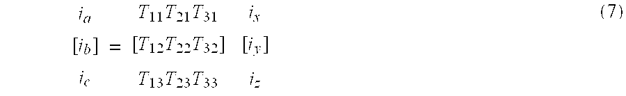
- a matrix converter is an array of switching elements. By controlling the switches in the array with signals from a control unit (not shown in FIG. 2 ), the matrix converter converts a fixed frequency, fixed amplitude AC-voltage at the grid side to a variable frequency, variable amplitude AC voltage at the generator side.
- a control unit not shown in FIG. 2
- the matrix converter converts a fixed frequency, fixed amplitude AC-voltage at the grid side to a variable frequency, variable amplitude AC voltage at the generator side.
- i a , i b and i c are the grid currents and i x , i y and i z are the generator currents, which in the implementation of FIG. 2 are rotor currents (in the implementation of FIG. 2A, the generator currents are stator currents).
- the elements of the transfer function have to be assigned values that assure output voltages and input currents follow their respective references.
- the elements in T can be calculated at any instant of time.
- the generator voltage and the grid currents are controllable parameters.
- the grid side voltage of the matrix converter is determined by the grid, while the generator currents are determined by the characteristics of the generator.
- a filter 240 smoothes the switched AC-current from power converter 250 , and passes the smoothed current to a tertiary winding of transformer 260 .
- Transformer 260 steps up the voltage to an amount, for example 10 kV, required for a power supply, such as a utility.
- the output of filter 240 could be directly coupled to the grid without any transformer or a separate transformer could be used.
- Wind turbine 200 A differs from wind turbine 200 in that wind turbine 200 A uses an induction generator 210 A that does not have brushes (electrical connections), to rotor 212 A.
- induction generator 210 A could be a squirrel-cage induction generator.
- generator 210 A Since generator 210 A does not have brushes, all of the power produced by generator 210 A is output from the stator 213 A.
- the three-phase output, for example, of stator 213 A is connected to a voltage gradient limiting circuit 220 A, which prevents large voltage changes across the generator windings.
- the output of this circuit is connected to a power converter 250 A, which is similar to power converter 250 of FIG. 2 and includes a matrix converter for converting the constant frequency, constant amplitude voltage from the grid supply to a variable frequency, variable amplitude voltage at the stator side of generator 210 A. Nevertheless, since the matrix converter of power converter 250 A must handle all of the power of the generator, the components constituting the matrix converter must withstand higher voltages and/or currents.
- a filter 240 A smoothes the constant-frequency AC current from power converter 250 A, and passes the smoothed current to a secondary winding of transformer 260 A.
- Transformer 260 A steps up the voltage to an amount, for example 10 kV, required for a power supply, such as a utility.
- Transformer 260 A does not require a tertiary winding.
- the output of filter 240 A could be directly coupled to the grid without any transformer.
- converter 250 is fed from transformer 260 .
- Transformer 260 has a primary winding connected to the supply (utility grid) and secondary and tertiary windings.
- Converter 250 is connected to the tertiary winding of transformer 260 , as mentioned above.
- the intrinsic property of matrix converters that limits the output voltage to be 0.866 of the input voltage does not constitute a problem in the present invention because a fairly arbitrary voltage can be chosen for the tertiary winding of transformer 260 . In contrast, this property can be a problem in systems in which a matrix converter is used to drive a variable speed standard motor.
- the voltage that is chosen for the tertiary windings of the transformer 260 is calculated in accordance with the desired speed range. For example, to achieve a dynamic speed range of ⁇ 30% around synchronous speed (i.e., maximum slip equals ⁇ 30%), the converter should be able to deliver an output voltage V r at the rotor terminals which satisfies the following equation:
- V r s ⁇ V r0 (8)
- V r0 is the standstill voltage at the rotor terminals when the stator is connected to the supply grid.
- the rotor converter when the standstill line-line voltage V r0 is 1820 V, the rotor converter must be able to deliver a voltage of 546 V (1820 V ⁇ 0.3) to achieve a speed range of ⁇ 30%.
- the line-line voltage at the grid side of the matrix converter V t3 has to be 630 V (546 V/0.866).
- the voltage at the tertiary winding should not be higher than necessary because that would require an increase in the voltage ratings of the switches in the converter.
- the peak voltage across the switch ⁇ circumflex over (v) ⁇ sw is:
- the switch voltage ratings are 892 V.
- the switch voltage ratings should be at least 1200V.
- the switches and the transformer have to be designed in accordance with the nominal stator voltage. No tertiary winding is present in transformer 260 A. If the nominal voltage of the generator (stator) is V sg , the necessary nominal voltage at the secondary transformer winding is calculated to be V sg /0.866. For example, if the nominal generator line-line voltage is 690 V, the necessary transformer line-line voltage becomes 796 V. Ideally, the switches in the matrix converter would have to withstand 1126V (796 V ⁇ 1.414). When safety factors are incorporated to compensate for over voltage conditions at the grid and intrinsic transient voltages in the converter, the switches should be rated higher than 1200 V, i.e. 1400-1700V. The intrinsic voltage gain of the matrix converter also might be overcome by adjusting the generator winding ratio in order to lower V r0 .
- Matrix converters 250 and 250 A convert a fixed-frequency AC voltage into a variable-frequency AC voltage.
- Various architectures are available for a matrix converter used in a wind turbine consistent with the present invention.
- the matrix converter can include any number of input phases or output phases, dependent on the system design.
- the bidirectional switches in the matrix converter can be of any design that allows for force-commutated control.
- FIGS. 3A-3E are examples of some of the different switching arrangements that can be used in a turbine consistent with the present invention.
- FIG. 3A illustrates a diode-embedded bidirectional switch.
- the diode-embedded bidirectional switch acts as a true bidirectional switch. Nevertheless, the diode-embedded bidirectional switch is not preferred since it does not permit control of the current direction and also because the current conducting path involves three semiconductors per phase.
- the switches shown in FIGS. 3B-3E can control the current direction, which is preferable in the phase commutations for the matrix converter. Also, a true bidirectional switch such as that described in U.S. Pat. No. 5,977,569 (incorporated herein by reference) can be used.
- FIG. 3B illustrates a common emitter bidirectional switch
- FIG. 3C illustrates a common collector bidirectional switch.
- these are the bidirectional switches that are most commonly used in matrix converter applications.
- a major advantage of these switches is that they can control the current direction while the diodes ensure safe commutation between current reversals.
- a drawback of the switches in FIGS. 3B and 3C is that they each use two semiconductors per phase in the current path.
- FIG. 3D illustrates a reverse blocking NPT-IGBT (Non-Punch-Through-Insulated Gate-Bipolar-Transistor) bidirectional switch.
- the switch of FIG. 3D has only one semiconductor per phase in the current conducting path. As a result, the conduction line losses using this type of switch can be lower than the losses that occur with the switches shown in FIGS. 3A-3C. Due to the lack of diodes, however, the switch of FIG. 3D does not have natural commutation properties. Consequently, there are difficulties in current reversals.
- the switch in FIG. 3D must be built from two NPT-IGBT's without anti parallel diodes so that the grid supply is not constantly short circuited.
- FIG. 3E is realized from a standard H-bridge module and becomes a parallel connection of a common emitter and a common collector configuration. For high power levels where the currents are so high that paralleling of bidirectional switches have to be used the configuration in FIG. 3E might be the best solution.
- the current direction is controllable, exactly as for the witch configuration in FIGS. 3B-D and further, the anti parallel diodes ensure safe communications during current reversals.
- gate signals (high) should be impressed at gate S 2 and gate S 3 allowing a current path through T 2 , D 4 and through D 1 T 3 .
- gate signals should be impressed at gate S 2 and gate S 4 , allowing a current path through D 3 T 1 and through T 4 D 2 .
- a switch realized from the standard H-bridge module in FIG. 3E is preferred in the present invention because the H-bridge module is an existing technology and by using existing technology, the present invention is not tied to a particular manufacturer of a special module, thereby reducing the cost of the wind turbine component.
- SEMIKRON manufactures intelligent H-bridge modules incorporating both protection, deadtime generation and insulated gate drivers.
- FIG. 4 illustrates another way to reconfigure existing technology to produce a common collector bidirectional switch.
- FIG. 4 illustrates a pair of transistors 400 and 410 having diodes 420 and 430 connected in parallel between their emitters and collectors.
- Transistors 400 and 410 and diodes 420 and 430 are typically encased in a package 440 referred to as a module.
- Module 440 provides external connections to the gate G 1 , emitter E 1 , and collector C 1 of transistor 400 as well as the gate G 2 , emitter E 2 , and collector C 2 of transistor 410 . Connecting the external connections C 1 and C 2 together produces the common collector switch of FIG. 3C, while connecting E 1 and E 2 produces a common emitter switch.
- a switching array of a matrix converter 250 includes nine modules 440 .
- EUPEC manufactures modules FF400R12KL4 and FF800R12KL4C, which can be used to produce the bidirectional switch of FIG. 4 (depending on the rated output power of the wind turbine).
- Table 1 illustrates characteristics of transistors that can be used in high-power wind turbine applications consistent with the present invention.
- FIGS. 5 and 6 illustrate another way to produce a bidirectional switch using existing technology.
- Three six-pack modules along with 9 dual pack additional diodes can be used to produce the nine bidirectional switches for a three phase to three phase matrix converter.
- FIG. 5 shows a six-pack module having six transistors 500 , 505 , 510 , 515 , 520 , and 525 , each having an associated diode 501 , 506 , 511 , 516 , 521 , or 526 , respectively, connected in parallel between the emitter and collector of the corresponding transistor.
- the emitter E 11 and collector C 12 of transistors 500 and 505 are connected together inside module 530 , as are emitter E 21 and collector C 22 of transistors 510 and 515 and emitter E 31 and collector E 32 of transistors 520 and 525 .
- FIG. 6 shows a realization of one bidirectional switch for one of the portions in FIG. 5 .
- the input of the switch is the common emitter/collector connection of the six pack and the output of the switch is the node between the two external diodes.
- This bidirectional switch is neither a common collector switch nor a common emitter switch. Therefore, it requires a high number of insulated gate drives (for example, twelve for a three phase to three phase matrix converter).
- the common collector bidirectional switch of FIG. 4 is preferable to the FIG. 6 switch because it reduces the number of insulated gate drives to six and avoids the additional diodes.
- FIGS. 7-9 illustrate operation of a control system for a wind turbine consistent with the present invention. While FIGS. 7-9 focus on control of wind turbine 200 shown in FIG. 2, the control of wind turbine 200 A shown in FIG. 2A can be derived from the following description.
- FIG. 7 illustrates a high-level view of a control system for the wind turbine consistent with the embodiment of FIG. 2 .
- FIG. 9 illustrates the functionality of modulator 730 of FIG. 7 .
- Modulator 730 of FIG. 7 includes commutation logic as shown in FIG. 9 at 930 .
- FIGS. 10 and 11 provide an example of the functionality of the commutation logic.
- a control system 700 outputs signals to control matrix converter 250 .
- the control system can include a Digital Signal Processing Unit (DSP), for example, the TMS3200C32 made by Texas Instruments. To increase processing power, additional DSPs can be included and may operate independently or in a master/slave manner.
- Control system 700 can also include components such as memory, input devices, output devices, a display, other user interfaces, and network connections to other computer systems.
- DSP Digital Signal Processing Unit
- Control system 700 is a power control system that controls the overall power of the wind turbine. Control system 700 does not directly control other parameters, such as generator torque. Nevertheless, to provide increased protection for the generator and wind turbine elements (such as the gearbox, not shown), control system 700 can be implemented as a torque control system. Examples of torque control systems are described in U.S. Pat. Nos. 5,083,039, 5,225,712, 6,137,187 and PCT Application U.S. Ser. No. 99/07996. Additionally, the control can be implemented as direct torque control to achieve faster response time for the real power P and reactive power Q. In this regard, see Domenico Casadei et al., “The Use of Matrix Converters in Direct Torque Control of Induction Machines,” 2 IEEE Industrial Electronics Society 744-749 (1998) (incorporated by reference herein in its entirety).
- the inputs to power control system 700 are desired amounts of total active power PMG_REF and reactive power QMG_REF.
- the desired amount of real power is based on the average power available in the wind at a given point in time.
- Various methods are available to estimate the amount of power available in the wind. For example, the estimate can be based on a direct measurement of wind speed or on a predicted wind speed, or on a combination of the above, as known to persons in the art.
- the desired amount of reactive power is not based on wind speed. Instead, the desired reactive power can be set to any level by the operator of the wind turbine.
- the wind turbine can sense the power condition of the supply (utility grid) and determine the amount of reactive power needed to correct this condition. Power in the wind can also be predicted based on knowledge about power delivered to the grid, speed of the generator and the pitch angle of the blades, but other ways to predict power in the wind are also possible.
- the real and reactive power references PMG_REF and QMG_REF shown in FIG. 7 are compared to measured values of real and reactive power PMG and QMG of the wind turbine.
- the results of these comparisons are fed into a P and Q controller.
- the P and Q controller converts the results into reference commands for the direct and quadrature components of the rotor current, i rd — ref and i rq — ref .
- the reference signals for the direct and quadrature rotor currents are compared to measured values of the direct and quadrature rotor currents, i rd and i rq .
- the results of this comparison are fed into current controller 720 , which produces the desired direct and quadrature rotor reference voltages u ra — ref and u rb — ref .
- FIG. 8 A more detailed control algorithm for determining u ra — ref and u rb — ref is shown in FIG. 8 .
- One particular feature of the control algorithm shown in FIG. 8 is that it permits a sensorless determination of rotor position. It is important in a control system of a generator to detect the slip angle, i.e., the angle between the stator voltage vector and the rotor position. This is a relatively easy task using a grid angle, which is determined below, and a physical rotor position encoder. Nevertheless, such an encoder can decrease the reliability of the wind turbine. Further, maintenance of the encoder is required to ensure its accuracy.
- FIG. 8 A more detailed control algorithm for determining u ra — ref and u rb — ref is shown in FIG. 8 .
- One particular feature of the control algorithm shown in FIG. 8 is that it permits a sensorless determination of rotor position. It is important in a control system of a generator to detect the slip angle, i.e.,
- the elements between the inputs OMEGAG and OMEGAS and output SLIP on FIG. 8 are portions of the rotor position sensorless path, whereas the elements between the input RHOG_ENC and output SLIP are portions of a path employing a rotor position encoder.
- FIG. 9 shows a modulator 730 implemented as a dedicated control circuit.
- modulator 730 could be integrated with controller 720 and its processor.
- the function of modulator 730 is to turn on and off the appropriate switches inside the matrix converter at the appropriate times, i.e., to determine the duty cycles d ⁇ , d ⁇ , d ⁇ , and d ⁇ of the switches.
- rotor voltage references u ra — ref and u rb — ref are input from the current controller 720 of FIG. 7 to modulator 730 , along with information about the angle of the grid voltage derived from the three phase voltages of the supply grid voltages u a , u b and u c (or a direct input of the grid angle).
- a further input, which is set by the user, is the desired angle ( ⁇ i . between the supply grid current and supply grid voltage, which is related to the desired power factor (cos ⁇ i ) of the matrix converter.
- angle and sector calculators 900 compute commands used in duty cycle calculators 910 to determine the duty cycles for the switches of the matrix converter. Once the duty cycles d ⁇ , d ⁇ , d ⁇ , and d ⁇ of the switches are calculated, PWM generator 920 computes nine gate signals for controlling the switches. Commutation logic 930 converts the nine gate signals into eighteen gate signals to control the bidirectional switches in the matrix converter. The logic 930 uses an input of the direction of the three rotor currents in order to achieve safe phase commutations, as discussed above. Phase commutations occur, for example, when rotor phase x has to be shifted from being connected to grid phase a to grid phase b. In addition, a shut down signal is input to modulator 730 to shut down the matrix converter in any failure situation (for example, over voltage, over current, or over temperature).
- the main grid angle is merely a simulation variable.
- the main grid angle is detected from measurements, even under unbalanced and distorted conditions, using a control algorithm. This algorithm is illustrated in FIG. 12 .
- the grid angle that is input to the modulator 730 of FIG. 9 is calculated using only the nominal main grid frequency ⁇ g and the periodically appearing zero-crossings of the grid voltages u a , u b , and u c .
- the grid side voltages u a , u b , and u c are input to the grid angle calculator 1350 of FIG. 12 .
- the voltages are passed through a low pass filter 1300 to eliminate measurement noise and high-frequency transients appearing on the supply grid.
- the filtered supply grid voltages are then input to a zero crossing detector 1310 .
- a phase-lock-loop (PLL) 1320 receives the output of zero crossing detector 1310 and, depending on which phase has crossed zero, outputs 0, 2 ⁇ /3 or ⁇ 2 ⁇ /3. To compensate for the phase displacement through filter 1300 , a linear correction factor 1/û is incorporated into the algorithm. The error between the actual angle (output from PLL circuit plus correction) and the estimated angle, which is a feedback signal, is input to a PI-controller 1330 . The output from PI-controller 1330 is added to the nominal angular frequency of the main grid ⁇ g and provided to integrator 1340 . Integrating on the corrected angular frequency gives a phase angle, which is fed back to PI-controller 1330 .
- the system described by Zhang and Watthanasarn provides only simulation results and therefore does not realize many of the problems that have to be faced when an implementation is attempted, such as the use of protection circuits, voltage gradient limiting circuits, and sensorless operation.
- the system described by Zhang and Wafthanasarn can not use circulating reactive power (because only stator quantities are controlled) to increase the rotor currents and thereby improving the position sensorless control at light loads.
- control system 700 controls the matrix converter 250 , rather than both the AC to DC converter 151 and the DC to AC converter 154 of FIG. 1, the control of wind turbine 200 is more efficient than the control of wind turbine 100 , which employs a DC link 152 .
- FIG. 10 is a schematic diagram of six switches and six diodes for a single output phase of the matrix converter in power converter 250 .
- Each switch has a gate (not shown in FIG. 10) receiving a gate signal for turning the switch on or off.
- Commutation logic 930 controls the switches by sending a respective gate signal to each of the six gates, as well as the respective 12 gate signals for the other two phases. These eighteen gate signals thus control the matrix converter in power converter 250 .
- the DSP will control less gate signals, e.g., just nine gate signals.
- One or more logic devices can be used to reduce the processing burden on a DSP in control system 700 .
- an ASIC that handles phase commutations can reduce the number of gate signals of the matrix converter to be controlled.
- Phase commutation can be explained with reference to FIGS. 10 and 11.
- the current i o of generator phase x is positive in accordance with the direction in FIG. 10 and drawn from grid phase “a”, i.e. switch S a1 is on and conducting and switch S a2 is on and non-conducting (reverse biased).
- the modulator of FIG. 7 demands a new voltage vector to be applied on the rotor.
- the modulator can command generator phase “x” be connected to grid phase “b” instead of grid phase “a.”
- a safe phase commutation procedure has to be followed to shift (commutate) from grid phase “a” to grid phase “b.”
- FIG. 11 illustrates a safe commutation procedure.
- the safe commutation provides a proper switching sequence. For example, the modulator orders a shift from switch state 11-00-00 to switch state 00-11-00.
- switch S a2 which is non-conducting, should be turned off bringing the switch state to 10-00-00 (this is a soft switching since the current through the switch is zero and the voltage across the switch is almost zero).
- the switch S b1 is turned on and the switch state becomes 10-10-00 (If the voltage in grid phase “a” is higher than the voltage in grid phase “b” at the switching instant, the turn on of switch S b1 becomes a soft turn-on, otherwise it is a hard turn-on).
- switch S a1 is turned off and the switch state becomes 00-10-00 (If the voltage of grid phase “b” is higher than grid phase “a” at the switching instant, the turn-off of switch S a1 becomes a soft turn-off, otherwise it is a hard turn-off). Finally, to complete the commutation procedure, switch S b2 is turned on (which becomes a soft turn on).
- FIG. 11 illustrates a four step algorithm for commutating switches between two arbitrary input phases and an output.
- the algorithm of FIG. 11 allows the matrix converter to use switches that do not have infinite switching times. If a special algorithm is not used, commutation between two input phases could result in a violation of the two basic control rules of a matrix converter: (1) a matrix converter is not allowed to make a short circuit to the supply grid, and (2) a matrix converter must always provide a current path for inductive generator current.
- Various commutation strategies have been proposed for a matrix converter, and the present invention can be implemented with any of these strategies. For example, R. R.
- FIG. 11 shows a preferred commutation strategy consistent with the present invention.
- the switching states shown in the left half of FIG. 11 are entered.
- the switching states in the right half are entered.
- the switching states in the shadowed boxes are transitional states while the switching states in the white boxes are the stationary states.
- current i o can be drawn from input phase a in one condition.
- both switches S a1 and S a2 are turned on, i.e., the stationary switch state is 11-00-00.
- the modulator demands a commutation from input phase a to input phase b.
- the non-conducting switch S a1 is turned off and then the switch state is 10-00-00.
- S b1 is turned on and input phase b is able to conduct the current.
- the switch state is 10-10-00.
- switch S a1 turns off and S b2 is finally turned on to complete the four-step commutation procedure.
- modulator 730 creates switching commands based on voltage references u ra — ref and u rb — ref .
- modulation strategies are known. These strategies can be divided into five categories: (1) the direct transfer function, (2) the indirect transfer function, (3) carrier-based modulation, (4) space vector modulation, and (5) indirect space vector modulation.
- Marco Venturini “A New Sine Wave In, Sine Wave Out Conversion Technique Eliminates Reactive Elements” Powercont. P. E3-1-E3-15 (1980) (incorporated herein by reference) describes a direct transfer function approach. Modulation is based on solving the matrix equation using a sinusoidal reference for the input current and the output voltage. This approach, however, restricts the output voltage to 0.5 times the input voltage. The voltage transfer ratio can be increased to 0.866 times the input voltage by adding a harmonic component to the output reference voltage. See Alberto Alesina and Marco Venturini, “Intrinsic Amplitudes and Optimum Design of Direct PWM AC-AC Converters” IEEE Power Electronics Specialists Conference 1284-1291 (1988) (incorporated herein by reference).
- indirect space vector modulation is the combination of principles from the indirect transfer function approach with principles from space vector modulation.
- SVM is performed individually for rectification and inversion.
- the number of switchings is preferably optimized to achieve lower switching losses. See P. Nielsen and F. Blaabjerg and J. K. Pedersen; “Space vector modulated matrix converter with minimized number of switchings and a feedforward compensation of input voltage unbalance” IEEE international conference on power electronics, drives and energy systems for industrial growth, Vol. 2, pp. 833-839, January, 1996.
- FIG. 14 illustrates implementing control system 700 using various analog and digital signals.
- the analog signals should include three measurements of the supply grid voltage (12 bit) 1410 , three measurements of the rotor phase current (12 bit) 1420 , and three measurements of the supply grid current (12 bit) 1430 .
- the digital signals include eighteen over voltage protection signals 1440 , eighteen overcurrent protection signals 1444 , eighteen overtemperature protection signals (one per switch) 1448 , eighteen gate signals (only nine from the microprocessor when an ASIC is used) 1450 , an on/off signal 1460 and a feedback signal 1465 used in coupling the stator and the supply grid, a signal to control the Y, ⁇ converter 1470 , a feedback signal from the Y, ⁇ converter 1475 , and digital encoder signals 1480 .
- a nominal rotor current can be 300 A.
- the rotor current can be 800 A.
- the nominal rotor voltage at 100% slip can be 1850 V.
- the overcurrent and over voltage protection signals should be designed to be triggered in accordance with these values. Of course, these values are only examples, and the values would vary for different generator constructions.
- FIG. 13 illustrates a configuration to protect matrix converter 250 .
- the protection of the matrix converter consists of a rotor circuit clamp 1700 and a snubber circuit 1710 .
- the snubber 1710 acts as a diode clamp circuit across the matrix converter. This snubber performs two different functions. In normal operation, snubber 1710 clamps any over voltages across the switches in the matrix converter. Over voltages typically are caused by current changes across the leakage inductances of the power switch matrix during commutation. When the matrix converter receives an error signal, all the switches in the matrix converter are turned off. This action violates one of the basic control rules of the matrix converter, by interrupting the inductive generator current. If no current path is provided for this inductive current) the voltage across the switches in the matrix converter increases and the converter will be damaged.
- the diodes provide an alternative current path. Therefore, in a fault situation, the clamp circuit or snubber performs the additional function of absorbing the energy in the leakage inductances of the rotor circuit and the energy in the rotor filter.
- Circuit 1720 in FIG. 13 can be designed as two diode bridges sharing a minor common capacitor 1730 . After grid connection of the converter, capacitor 1730 is charged to the rectified grid voltage. Also, during grid failure, the voltage across the rotor windings can be high, causing damaging currents and voltages for the matrix converter. To prevent damage to the matrix converter, an over voltage protection circuit (OVP) 1700 acts as a rotor voltage clamp. In case of a grid failure, the switch (shown as thyristor 1710 in FIG. 13) clamps the rotor voltage until the stator is disconnected from the supply grid, and the rotor currents are zero. Papers, such as P. Nielsen, F. Blaabjerg, J. K.
- This entire protection circuit requires inclusion of eighteen additional diodes, DC-link capacitor 1730 , and switch 1710 .
- the DC-link capacitor does not significantly impact the mean-time-between-failures for the wind turbine, since this DC-link capacitor is much smaller than the DC-link capacitor of FIG. 1 .
- This DC-link capacitor voltage in the clamp circuit can be used as a power supply for the controller of the matrix converter.
- the DC-link capacitor can be energized from the energy stored in the generator to maintain the controller circuits active (as shown in FIG. 13) and when the grid disturbance ends, the matrix converter will be able to resume control of the generator. This back up of the controller for the matrix converter enables the controller to operate the generator immediately after a disturbance has ended. This is an important feature for a grid connected wind turbine.
- Wind turbines using matrix converters are described above. These wind turbines operate at high power and can provide reliable alternatives to fossil fuel generation of electricity for a utility grid.
Abstract
Description


| TABLE 1 | |||
| 850 |
2 MW | ||
| FF400R12KL4 | FF800R12 KL4C | ||
| VCES = 1200 V | VCES = 1200 V | ||
| IC = 400 A | IC = 800 A | ||
| ICRM = 800 A | ICRM = 1600 A | ||
| 140 × 130 |
140 × 130 mm | ||
Claims (20)
Priority Applications (2)
| Application Number | Priority Date | Filing Date | Title |
|---|---|---|---|
| US09/862,316 US6566764B2 (en) | 2000-05-23 | 2001-05-23 | Variable speed wind turbine having a matrix converter |
| US10/394,263 US6856038B2 (en) | 2000-05-23 | 2003-03-24 | Variable speed wind turbine having a matrix converter |
Applications Claiming Priority (2)
| Application Number | Priority Date | Filing Date | Title |
|---|---|---|---|
| US20631300P | 2000-05-23 | 2000-05-23 | |
| US09/862,316 US6566764B2 (en) | 2000-05-23 | 2001-05-23 | Variable speed wind turbine having a matrix converter |
Related Child Applications (1)
| Application Number | Title | Priority Date | Filing Date |
|---|---|---|---|
| US10/394,263 Continuation US6856038B2 (en) | 2000-05-23 | 2003-03-24 | Variable speed wind turbine having a matrix converter |
Publications (2)
| Publication Number | Publication Date |
|---|---|
| US20020079706A1 US20020079706A1 (en) | 2002-06-27 |
| US6566764B2 true US6566764B2 (en) | 2003-05-20 |
Family
ID=22765816
Family Applications (2)
| Application Number | Title | Priority Date | Filing Date |
|---|---|---|---|
| US09/862,316 Expired - Lifetime US6566764B2 (en) | 2000-05-23 | 2001-05-23 | Variable speed wind turbine having a matrix converter |
| US10/394,263 Expired - Fee Related US6856038B2 (en) | 2000-05-23 | 2003-03-24 | Variable speed wind turbine having a matrix converter |
Family Applications After (1)
| Application Number | Title | Priority Date | Filing Date |
|---|---|---|---|
| US10/394,263 Expired - Fee Related US6856038B2 (en) | 2000-05-23 | 2003-03-24 | Variable speed wind turbine having a matrix converter |
Country Status (4)
| Country | Link |
|---|---|
| US (2) | US6566764B2 (en) |
| EP (1) | EP1284045A1 (en) |
| AU (1) | AU2001274396A1 (en) |
| WO (1) | WO2001091279A1 (en) |
Cited By (131)
| Publication number | Priority date | Publication date | Assignee | Title |
|---|---|---|---|---|
| US20030025333A1 (en) * | 2001-07-19 | 2003-02-06 | Kabushiki Kaisha Toshiba | Turbine-generator equipment and installation method thereof |
| US20030030344A1 (en) * | 2000-09-20 | 2003-02-13 | Andreas Hatz | Arrangement and method for producing different output volatges with an alternating current generator |
| US20030078683A1 (en) * | 2001-09-05 | 2003-04-24 | Eric Hartman | System and method for on-line training of a support vector machine |
| US20030112643A1 (en) * | 2000-02-04 | 2003-06-19 | Mikko Salama | Pwm frequency converter |
| US20030151259A1 (en) * | 2002-02-11 | 2003-08-14 | Lorenz Feddersen | Variable speed wind turbine having a passive grid side rectifier with scalar power control and dependent pitch control |
| US20030173935A1 (en) * | 2000-03-11 | 2003-09-18 | Aloys Wobben | Synchronous generator |
| US20030218887A1 (en) * | 2002-04-30 | 2003-11-27 | Kojori Hassan A. | Synchronous and bi-directional variable frequency power conversion systems |
| US20030227172A1 (en) * | 2002-06-07 | 2003-12-11 | Erdman William L. | Wind farm electrical system |
| US20040022081A1 (en) * | 2002-05-31 | 2004-02-05 | Erickson Robert W | Variable-speed wind power system with improved energy capture via multilevel conversion |
| US20040026929A1 (en) * | 2000-05-23 | 2004-02-12 | Vestas Wind Systems A/S | Variable speed wind turbine having a matrix converter |
| US20040075278A1 (en) * | 2001-02-23 | 2004-04-22 | Jean-Marc Canini | Method and device for regulating a wind machine |
| US20040094964A1 (en) * | 1997-08-08 | 2004-05-20 | Mikhail Amir S. | Variable speed wind turbine generator |
| US20040178774A1 (en) * | 2003-01-27 | 2004-09-16 | Switched Reluctance Drives Limited | Variable reluctance generator |
| US20040257832A1 (en) * | 2003-01-23 | 2004-12-23 | Skeist S. Merrill | Permanent magnet induction machine |
| US20050012487A1 (en) * | 2003-01-23 | 2005-01-20 | Skeist S. Merrill | Doubly fed induction machine |
| US20050040655A1 (en) * | 2003-08-18 | 2005-02-24 | Wilkins Thomas A. | Continuous reactive power support for wind turbine generators |
| US20050046196A1 (en) * | 2003-09-03 | 2005-03-03 | Larsen Einar V. | Voltage control for wind generators |
| US20050116476A1 (en) * | 2002-01-29 | 2005-06-02 | Lorenz Feddersen | Circuit to be used in a wind power plant |
| US20050122752A1 (en) * | 2005-03-01 | 2005-06-09 | York International Corporation | System for precharging a DC link in a variable speed drive |
| DE10360462A1 (en) * | 2003-12-22 | 2005-07-14 | Repower Systems Ag | Wind energy plant with an autonomous control device with a reactive power and reactive power control module |
| US20050151377A1 (en) * | 2004-01-08 | 2005-07-14 | Hitachi, Ltd. | Wind turbine generator system |
| US20050179331A1 (en) * | 2002-03-28 | 2005-08-18 | Pietro Maddalena | Energy conversion apparatus with induction machine and method for operating the same |
| US20050236838A1 (en) * | 2004-04-23 | 2005-10-27 | Bernd Rosebrock | Protection for wind power station |
| WO2004098261A3 (en) * | 2003-05-02 | 2005-12-22 | Xantrex Technology Inc | Control system for doubly fed induction generator |
| US20050286279A1 (en) * | 2004-06-23 | 2005-12-29 | General Electric Company | Dual mode rectifier, system and method |
| US20060113800A1 (en) * | 2002-09-10 | 2006-06-01 | Wolf Willisch | Operating method for a a wind turbine with a supersynchronous cascade |
| US20060119105A1 (en) * | 2002-12-27 | 2006-06-08 | Junkoo Kang | Power generating system and its control method |
| US20060163881A1 (en) * | 2002-07-17 | 2006-07-27 | Andreas Bucker | Method for operating a wind power plant and method for operating it |
| US20060186670A1 (en) * | 2005-02-22 | 2006-08-24 | Hudson Raymond M | Method and apparatus for converting wind generated electricity to constant frequency electricity for a utility grid |
| US20060196203A1 (en) * | 2005-03-01 | 2006-09-07 | York International Corporation | System for precharging a DC link in a variable speed drive |
| US20060208493A1 (en) * | 2005-03-15 | 2006-09-21 | General Electric Company | Methods and apparatus for pitch control power conversion |
| US20060208685A1 (en) * | 2005-03-01 | 2006-09-21 | Schnetzka Harold R | System for precharging a DC link in a variable speed drive |
| US20060214428A1 (en) * | 2003-06-16 | 2006-09-28 | Repower Systems Ag | Wind farm |
| US20060267542A1 (en) * | 2005-05-27 | 2006-11-30 | Lixiang Wei | Pulse width modulation (PWM) rectifier with variable switching frequency |
| US20070008669A1 (en) * | 2005-07-07 | 2007-01-11 | Kamal Al-Haddad | Method and apparatus for providing a remedial strategy for an electrical circuit |
| US20070024059A1 (en) * | 2005-07-29 | 2007-02-01 | General Electric Company | System and method for power control in wind turbines |
| US20070029802A1 (en) * | 2003-04-08 | 2007-02-08 | Georg Moehlenkamp | Wind turbine for producing electrical power and a method of operating the same |
| US20070035136A1 (en) * | 2005-08-12 | 2007-02-15 | Wilhelm Janssen | Wind Turbine Over-Voltage Exposure |
| US20070081369A1 (en) * | 2003-09-19 | 2007-04-12 | Hidenori Hara | Pwm cycloconverter |
| US20070097565A1 (en) * | 2005-10-27 | 2007-05-03 | Shinya Oohara | Distributed generation system and power system stabilizing method |
| US20070126377A1 (en) * | 2005-10-07 | 2007-06-07 | Alstom Transport Sa | Method and system for supplying electrical power to a supply bus for an electric vehicle, recording medium, and vehicle for this method |
| US20070126406A1 (en) * | 2005-08-31 | 2007-06-07 | Prevailing Energy, Inc. | Turbine with Configurable Generator Circuit |
| US20070132248A1 (en) * | 2005-12-08 | 2007-06-14 | General Electric Company | System and method of operating double fed induction generators |
| US20070132410A1 (en) * | 2005-08-31 | 2007-06-14 | Thor Power Corp. | Control electronics for brushless dc motors |
| US20070139022A1 (en) * | 2003-12-19 | 2007-06-21 | Eiji Yamamoto | Method and apparatus for detecting input voltage of pwm cycloconverter |
| US20070164567A1 (en) * | 2006-01-19 | 2007-07-19 | General Electric Company | Wind turbine dump load system and method |
| US20070182383A1 (en) * | 2005-12-30 | 2007-08-09 | Korea Electrotechnology Research Institute | Electric power converting device and power converting method for controlling doubly-fed induction generator |
| WO2007109048A2 (en) * | 2006-03-16 | 2007-09-27 | International Components Corporation | A novel speed sensing circuit for a wind turbine generator |
| US20070246943A1 (en) * | 2006-04-25 | 2007-10-25 | The University Of New Brunswick | Stand-alone wind turbine system, apparatus, and method suitable for operating the same |
| US20070278797A1 (en) * | 2006-05-31 | 2007-12-06 | Flannery Patrick S | Power conditioning architecture for a wind turbine |
| US20070290506A1 (en) * | 2006-06-19 | 2007-12-20 | Reigh Walling | Methods and apparatus for supplying and/or absorbing reactive power |
| CN100359798C (en) * | 2003-05-27 | 2008-01-02 | Abb有限公司 | Method for controlling doubly-fed machine |
| US20080079263A1 (en) * | 2006-09-28 | 2008-04-03 | Mahesh Amritlal Morjaria | Method and apparatus for operating wind turbine generators |
| US20080157529A1 (en) * | 2006-12-29 | 2008-07-03 | Ingeteam, S.A. | Low voltage ride through system for a variable speed wind turbine having an exciter machine and a power converter not connected to the grid |
| US7425771B2 (en) | 2006-03-17 | 2008-09-16 | Ingeteam S.A. | Variable speed wind turbine having an exciter machine and a power converter not connected to the grid |
| US20080247211A1 (en) * | 2007-03-30 | 2008-10-09 | Alstom Technology Ltd | Active generator control sequence |
| US20080252076A1 (en) * | 2003-09-25 | 2008-10-16 | Jens Fortmann | Wind Power Plant Comprising a Reactive Power Module For Supporting a Power Supply System and Corresponding Method |
| US20080296897A1 (en) * | 2006-11-21 | 2008-12-04 | Parker-Hannifin Corporation | Variable speed wind turbine drive and control system |
| US20090008945A1 (en) * | 2006-03-17 | 2009-01-08 | Lars Helle | Protection System For An Electric Generator, Wind Turbine And Use Hereof |
| US20090059633A1 (en) * | 2005-04-15 | 2009-03-05 | Kabushiki Kaisha Yaskawa Denki | Matrix converter apparatus |
| US20090212564A1 (en) * | 2008-02-26 | 2009-08-27 | General Electric Company | Method and apparatus for assembling electrical machines |
| US20090254223A1 (en) * | 2006-10-02 | 2009-10-08 | Lars Helle | Method For Operating A Wind Turbine Connected To A Utility Grid During A Utility Disturbance, Wind Turbine And Wind Park |
| US20090251109A1 (en) * | 2008-04-04 | 2009-10-08 | General Electric Company | Systems and methods involving starting variable speed generators |
| US20090250931A1 (en) * | 2008-04-02 | 2009-10-08 | Nordex Energy Gmbh | Method for operating a wind energy plant with a doubly-fed asynchronous machine and wind energy plant with a doubly-fed asynchronous machine |
| US20090265040A1 (en) * | 2008-04-21 | 2009-10-22 | Paluszek Michael A | Matrix Converters For Wind Energy Conversion Systems |
| US20090278351A1 (en) * | 2006-03-17 | 2009-11-12 | Ingeteam S.A. | High voltage direct current link transmission system for variable speed wind turbine |
| US20100032958A1 (en) * | 2008-08-06 | 2010-02-11 | Infinite Wind Energy LLC | Hyper-surface wind generator |
| US20100038908A1 (en) * | 2004-08-06 | 2010-02-18 | Akira Kikuchi | Wind turbine generator system |
| US20100054941A1 (en) * | 2008-08-27 | 2010-03-04 | Till Hoffmann | Wind tracking system of a wind turbine |
| US20100085000A1 (en) * | 2008-10-03 | 2010-04-08 | Johnson Controls Technology Company | Variable speed drive for permanent magnet motor |
| US20100109447A1 (en) * | 2008-10-31 | 2010-05-06 | General Electric Company | Wide area transmission control of windfarms |
| US20100244773A1 (en) * | 2009-03-27 | 2010-09-30 | Gm Global Technology Operations, Inc. | Unity power factor isolated single phase matrix converter battery charger |
| US20110006528A1 (en) * | 2008-02-01 | 2011-01-13 | Woodward Seg Gmbh & Co. Kg | Method for operating a wind turbine |
| US20110031930A1 (en) * | 2009-08-05 | 2011-02-10 | Gm Global Technology Operations, Inc. | Systems and methods for bi-directional energy delivery with galvanic isolation |
| US20110074365A1 (en) * | 2009-09-30 | 2011-03-31 | Hitachi, Ltd. | Wind power generating system and control method for the same |
| US20110074151A1 (en) * | 2009-09-25 | 2011-03-31 | General Electric Company | Multi-use energy storage for renewable sources |
| US20110109085A1 (en) * | 2009-11-10 | 2011-05-12 | Nelson Robert J | Power Oscillation Damping Employing a Full or Partial Conversion Wind Turbine |
| US20110140433A1 (en) * | 2008-07-22 | 2011-06-16 | Vestas Wind Systems A/S | Method of controlling a variable speed wind turbine |
| US20110153099A1 (en) * | 2008-06-30 | 2011-06-23 | Vestas Wind Systems A/S | Method and system for controlling a wind power plant comprising a number of wind turbine generators |
| US20110182093A1 (en) * | 2010-01-28 | 2011-07-28 | Paul Brian Brogan | Current controller device and vector control method for controlling power conversion |
| US20110210552A1 (en) * | 2008-09-17 | 2011-09-01 | Bo Birkemose | Asynchronous Power Generator for a Wind Turbine |
| US20110227513A1 (en) * | 2009-11-04 | 2011-09-22 | Onuma Yusaku | Power converter device |
| US20110260454A1 (en) * | 2008-11-19 | 2011-10-27 | Woodward Kempen Gmbh | Device for controlling a double-fed asynchronous machine |
| US20110266800A1 (en) * | 2009-01-14 | 2011-11-03 | Ruben Alexis Inzunza Figueroa | Protection circuit applied to wind power generation system employing double-fed induction generator |
| US8106563B2 (en) | 2006-06-08 | 2012-01-31 | Exro Technologies Inc. | Polyphasic multi-coil electric device |
| KR101119323B1 (en) | 2004-09-29 | 2012-03-06 | 가부시키가이샤 야스카와덴키 | Parallel multiplex matrix converter |
| US8212445B2 (en) | 2004-08-12 | 2012-07-03 | Exro Technologies Inc. | Polyphasic multi-coil electric device |
| US20120169054A1 (en) * | 2010-01-21 | 2012-07-05 | Roos Paul W | Power Conversion and Energy Storage Device |
| US20120306203A1 (en) * | 2011-06-03 | 2012-12-06 | Detlef Drossel | Method for operating a wind turbine in the event of a grid error and a wind turbine for carrying out said method |
| US20130115043A1 (en) * | 2010-06-29 | 2013-05-09 | Vestas Wind Systems A/S | Rotational positioning system in a wind turbine |
| US8462528B2 (en) | 2010-07-19 | 2013-06-11 | GM Global Technology Operations LLC | Systems and methods for reducing transient voltage spikes in matrix converters |
| US8467197B2 (en) | 2010-11-08 | 2013-06-18 | GM Global Technology Operations LLC | Systems and methods for compensating for electrical converter nonlinearities |
| US8491262B2 (en) | 2011-10-27 | 2013-07-23 | General Electric Company | Method for shut down of a wind turbine having rotor blades with fail-safe air brakes |
| US20130187384A1 (en) * | 2010-03-31 | 2013-07-25 | Bing Li | Method of operating a wind turbine, wind turbine, wind turbine controlling system, and processing system |
| US20130188404A1 (en) * | 2010-08-10 | 2013-07-25 | Nabtesco Corporation | Indirect Matrix Converter |
| US20130215652A1 (en) * | 2010-09-22 | 2013-08-22 | Toshiba Mitsubishi-Electric Industrial Systems | Power converter apparatus |
| US8587962B2 (en) | 2010-11-08 | 2013-11-19 | GM Global Technology Operations LLC | Compensation for electrical converter nonlinearities |
| US8599577B2 (en) | 2010-11-08 | 2013-12-03 | GM Global Technology Operations LLC | Systems and methods for reducing harmonic distortion in electrical converters |
| US8614564B2 (en) | 2010-11-18 | 2013-12-24 | GM Global Technology Operations LLS | Systems and methods for providing power to a load based upon a control strategy |
| US8669669B1 (en) * | 2012-09-13 | 2014-03-11 | General Electric Company | Voltage control in a doubly-fed induction generator wind turbine system |
| US20140246856A1 (en) * | 2011-09-29 | 2014-09-04 | General Electric Company | Methods and systems for operating a wind turbine coupled to a power grid |
| US20140246900A1 (en) * | 2007-10-26 | 2014-09-04 | Frederick William Klatt | Brushless Multiphase Self-Commutation Control (or BMSCC) And Related Invention |
| US20140246854A1 (en) * | 2011-08-12 | 2014-09-04 | Openhydro Ip Limited | Method and system for controlling hydroelectric turbines |
| US8829858B2 (en) | 2011-05-31 | 2014-09-09 | GM Global Technology Operations LLC | Systems and methods for initializing a charging system |
| US20140292088A1 (en) * | 2011-01-12 | 2014-10-02 | Venpower Gmbh | Arrangement for feeding electrical energy into an energy supply system |
| US8860379B2 (en) | 2011-04-20 | 2014-10-14 | GM Global Technology Operations LLC | Discharging a DC bus capacitor of an electrical converter system |
| US8878495B2 (en) | 2011-08-31 | 2014-11-04 | GM Global Technology Operations LLC | Systems and methods for providing power to a load based upon a control strategy |
| US8941961B2 (en) | 2013-03-14 | 2015-01-27 | Boulder Wind Power, Inc. | Methods and apparatus for protection in a multi-phase machine |
| US20150115905A1 (en) * | 2012-04-10 | 2015-04-30 | Versitech Limited | Power Compensator |
| US9024559B2 (en) | 2010-05-04 | 2015-05-05 | Johnson Controls Technology Company | Variable speed drive |
| US20150131348A1 (en) * | 2012-06-18 | 2015-05-14 | Universite De Lorraine | Reversible matrix converter circuit |
| US20150308412A1 (en) * | 2012-12-06 | 2015-10-29 | Vestas Wind Systems A/S | A three-phase ac electrical sysyem, and a method for compensating an inductance imbalance in such a system |
| US20150333668A1 (en) * | 2013-01-22 | 2015-11-19 | Trane International Inc. | Variable frequency drive active harmonic mitigation controls and diagnostics |
| US20150365031A1 (en) * | 2014-06-13 | 2015-12-17 | Nordex Energy Gmbh | Method for controlling a wind turbine during an asymmetrical grid fault and a wind turbine |
| US9217419B2 (en) * | 2014-05-22 | 2015-12-22 | Industrial Cooperation Foundation Chonbuk National University | System and method for controlling voltage at point of common coupling of wind farm |
| US9267491B2 (en) | 2013-07-02 | 2016-02-23 | General Electric Company | Wind turbine rotor blade having a spoiler |
| US20160076518A1 (en) * | 2013-05-08 | 2016-03-17 | Consiglio Nazionale Delle Ricerche | Method and relevant system for converting mechanical energy from a generator actuated by a turbine into electric energy |
| US9371821B2 (en) | 2012-08-31 | 2016-06-21 | General Electric Company | Voltage control for wind turbine generators |
| US20160282392A1 (en) * | 2015-03-25 | 2016-09-29 | Research Cooperation Foundation Of Yeungnam University | Inverter vector driving system and method for estimating capacitance using the same |
| US9770991B2 (en) | 2013-05-31 | 2017-09-26 | GM Global Technology Operations LLC | Systems and methods for initializing a charging system |
| US9793827B2 (en) | 2013-03-14 | 2017-10-17 | Ge Energy Power Conversion Technology Ltd | Power conversion system and method |
| US20190234378A1 (en) * | 2018-01-26 | 2019-08-01 | General Electric Company | Wind power generation system and controlling method thereof |
| US10700624B2 (en) * | 2016-08-26 | 2020-06-30 | Vestas Wind Systems A/S | Control of a wind turbine generator for reduced tonal audibility |
| US10742149B1 (en) * | 2019-04-22 | 2020-08-11 | General Electric Company | System and method for reactive power control of a wind turbine by varying switching frequency of rotor side converter |
| US10859064B2 (en) * | 2016-12-27 | 2020-12-08 | Vestas Wind Systems A/S | Control system for modular multilevel converter |
| US11081996B2 (en) | 2017-05-23 | 2021-08-03 | Dpm Technologies Inc. | Variable coil configuration system control, apparatus and method |
| US11121653B2 (en) * | 2018-02-16 | 2021-09-14 | Honda Motor Co., Ltd. | Inverter generator |
| US20220049679A1 (en) * | 2020-08-14 | 2022-02-17 | Wobben Properties Gmbh | Oscillation damping in wind power installations |
| US11353004B2 (en) * | 2017-06-13 | 2022-06-07 | Wobben Properties Gmbh | Wind turbine comprising a gearless generator and a generator filter |
| US11708005B2 (en) | 2021-05-04 | 2023-07-25 | Exro Technologies Inc. | Systems and methods for individual control of a plurality of battery cells |
| US11722026B2 (en) | 2019-04-23 | 2023-08-08 | Dpm Technologies Inc. | Fault tolerant rotating electric machine |
Families Citing this family (114)
| Publication number | Priority date | Publication date | Assignee | Title |
|---|---|---|---|---|
| US6670721B2 (en) * | 2001-07-10 | 2003-12-30 | Abb Ab | System, method, rotating machine and computer program product for enhancing electric power produced by renewable facilities |
| US20030216893A1 (en) * | 2002-05-17 | 2003-11-20 | Warren Hendrickson | Method of designing and constructing a power plant |
| US8533307B2 (en) | 2002-07-26 | 2013-09-10 | Robert Bosch Gmbh | Method and device for monitoring a data transmission |
| AU2002336921A1 (en) * | 2002-11-01 | 2004-05-25 | Vestas Wind Systems A/S | Circuit arrangement for use in a variable speed wind turbine system comprising a double-fed induction generator and a back-to-back converter |
| FI116174B (en) | 2003-04-08 | 2005-09-30 | Abb Oy | Configuration and Method for Protecting Directional Devices |
| US7042110B2 (en) * | 2003-05-07 | 2006-05-09 | Clipper Windpower Technology, Inc. | Variable speed distributed drive train wind turbine system |
| US7233129B2 (en) * | 2003-05-07 | 2007-06-19 | Clipper Windpower Technology, Inc. | Generator with utility fault ride-through capability |
| US6995992B2 (en) * | 2003-06-20 | 2006-02-07 | Wisconsin Alumni Research Foundation | Dual bridge matrix converter |
| DE10330473A1 (en) * | 2003-07-05 | 2005-01-27 | Alstom Technology Ltd | Frequency converter for high-speed generators |
| MXPA06000348A (en) * | 2003-07-10 | 2006-03-28 | Magnetic Applic Inc | Compact high power alternator. |
| US7061134B2 (en) * | 2003-08-01 | 2006-06-13 | General Motors Corporation | Method and system for improved thermal management of a voltage source inverter operating at low output frequency utilizing a zero vector modulation technique |
| US7271500B1 (en) | 2004-01-13 | 2007-09-18 | Hitachi, Ltd. | Electrical rotating machine control unit and power generation system |
| JP4155196B2 (en) * | 2004-01-13 | 2008-09-24 | 株式会社日立製作所 | Rotating electrical machine control device and power generation system |
| US7045986B2 (en) * | 2004-02-20 | 2006-05-16 | Honeywell International Inc. | Position sensing method and apparatus for synchronous motor generator system |
| DE102004016034A1 (en) * | 2004-03-30 | 2005-10-20 | Alstom Technology Ltd Baden | Electrical system for coupling a power supply network and a central DC voltage line and method for operating such a system |
| DE102004016464A1 (en) * | 2004-03-31 | 2005-11-03 | Alstom Technology Ltd | Method for calculating and assessing the frequency spectrum of a matrix converter |
| ITVA20040055A1 (en) * | 2004-11-23 | 2005-02-23 | St Microelectronics Srl | METHOD AND CIRCUIT OF CONTROL OF AN ELECTRICITY GENERATION SYSTEM |
| MX2007009324A (en) * | 2005-02-02 | 2007-11-14 | Magnetic Applic Inc | Pulse generator for a controlled rectifier. |
| JP2006246661A (en) * | 2005-03-04 | 2006-09-14 | Neic-Japan Corp | Wind power generator |
| NZ565921A (en) * | 2005-07-15 | 2011-05-27 | Southwest Windpower Inc | Wind turbine and method of manufacture |
| JP4561518B2 (en) * | 2005-07-27 | 2010-10-13 | 株式会社日立製作所 | A power generation apparatus using an AC excitation synchronous generator and a control method thereof. |
| DE102005036317B4 (en) * | 2005-07-29 | 2010-02-11 | Aloys Wobben | Method and device for determining the power loss of an electronic switch, inverter, wind turbine with methods of control |
| US20070110579A1 (en) * | 2005-11-14 | 2007-05-17 | Ross Robert G Sr | Vertical axis wind turbine energy converter (VAWTEC) |
| ES2298014B1 (en) * | 2005-12-30 | 2009-07-23 | Universidad Publica De Navarra | METHOD AND SYSTEM FOR THE PROTECTION OF AN ELECTRICAL GENERATION INSTALLATION CONNECTED TO AN ELECTRICAL NETWORK BEFORE THE PRESENCE OF VOLTAGE HOLES IN THE NETWORK. |
| US7768165B2 (en) * | 2006-02-02 | 2010-08-03 | Magnetic Applications, Inc. | Controller for AC generator |
| DE102006007919B4 (en) * | 2006-02-21 | 2008-01-24 | Nordex Energy Gmbh | Method for operating a wind energy plant |
| US7508089B2 (en) * | 2006-03-16 | 2009-03-24 | International Components Corporation | Over speed control circuit for a wind turbine generator which maximizes the power exported from the generator over time |
| US8169179B2 (en) * | 2006-08-22 | 2012-05-01 | Regents Of The University Of Minnesota | Open-ended control circuit for electrical apparatus |
| CN101512143A (en) * | 2006-09-29 | 2009-08-19 | Abb研究有限公司 | Control method |
| US7593243B2 (en) * | 2006-10-09 | 2009-09-22 | Honeywell International Inc. | Intelligent method for DC bus voltage ripple compensation for power conversion units |
| EP2111347A4 (en) * | 2007-01-30 | 2011-08-03 | Gordon Ewbank Dower | Vehicle power and speed control systems |
| DE102007006966A1 (en) * | 2007-02-13 | 2008-08-14 | Robert Bosch Gmbh | Drive device for driving multiple axes |
| DE102007007913A1 (en) * | 2007-02-14 | 2008-08-21 | Alstom Technology Ltd. | Method for operating a power plant |
| WO2008098894A1 (en) * | 2007-02-14 | 2008-08-21 | Alstom Technology Ltd | Power plant comprising a consumer and method for operating said power plant |
| EP2122129B1 (en) * | 2007-02-14 | 2018-04-11 | General Electric Technology GmbH | Power plant system and method for the operation thereof |
| JP5091256B2 (en) * | 2007-02-14 | 2012-12-05 | アルストム テクノロジー リミテッド | Operation method of power generation equipment |
| US7851933B2 (en) * | 2007-03-15 | 2010-12-14 | Duffey Christopher K | System for generating constant speed output from variable speed input |
| JP2008306776A (en) * | 2007-06-05 | 2008-12-18 | Hitachi Ltd | Wind power generation system and control method thereof |
| US20090011143A1 (en) * | 2007-06-22 | 2009-01-08 | Matsushita Electric Industrial Co., Ltd. | Pattern forming apparatus and pattern forming method |
| WO2009003478A2 (en) * | 2007-06-29 | 2009-01-08 | Vestas Wind Systems A/S | Thermal monitoring of doubly-fed generator |
| DE102007042246A1 (en) * | 2007-09-06 | 2009-05-14 | Woodward Seg Gmbh & Co. Kg | Method and control unit for short-circuit current reduction in a double-fed asynchronous machine |
| US8217616B2 (en) * | 2007-11-02 | 2012-07-10 | HJamilton Sundstrand Corporation | Electric motor control with buck boost converter |
| US7884492B2 (en) * | 2007-11-13 | 2011-02-08 | General Electric Company | Methods and systems for wind turbine generators |
| US7710058B2 (en) * | 2007-12-13 | 2010-05-04 | Hamilton Sundstrand Corporation | Motor drive architecture for high frequency AC bus |
| WO2009084354A1 (en) | 2007-12-27 | 2009-07-09 | Kabushiki Kaisha Yaskawa Denki | Winding change-over switch of three-phase ac motor |
| DE102008003299B4 (en) * | 2008-01-07 | 2016-06-09 | Woodward Kempen Gmbh | Method for operating a wind energy plant |
| US7894211B2 (en) | 2008-01-24 | 2011-02-22 | Honeywell International Inc. | Micro wind turbine topology for small scale power generation |
| CA2714579A1 (en) * | 2008-02-07 | 2009-08-13 | Magnetic Applications Inc. | Compact high power alternator |
| US8109722B2 (en) * | 2008-03-24 | 2012-02-07 | Nordic Windpower Ltd. | Turbine and system for generating power from fluid flow and method therefor |
| KR100985921B1 (en) | 2008-04-23 | 2010-10-11 | 명지대학교 산학협력단 | wind power system using doubly fed induction generator and control method thereof |
| WO2009135284A1 (en) * | 2008-05-05 | 2009-11-12 | Xantrex International | Method and apparatus for converting direct current into an alternating current |
| WO2009155467A2 (en) * | 2008-06-18 | 2009-12-23 | Duffey Christopher K | Variable speed synchronous generator |
| JP4698718B2 (en) * | 2008-09-30 | 2011-06-08 | 株式会社日立製作所 | Wind turbine generator group control device and control method |
| US20110210550A1 (en) * | 2008-10-03 | 2011-09-01 | Mats Leijon | Power generation unit and a method generating electric energy |
| US8050887B2 (en) * | 2008-12-22 | 2011-11-01 | General Electric Company | Method and system for determining a potential for icing on a wind turbine blade |
| US8350523B2 (en) * | 2009-08-05 | 2013-01-08 | GM Global Technology Operations LLC | Charging system with galvanic isolation and multiple operating modes |
| US7908035B2 (en) * | 2009-08-31 | 2011-03-15 | General Electric Company | System and method for wind formulary |
| US8288887B2 (en) * | 2009-11-19 | 2012-10-16 | GM Global Technology Operations LLC | Systems and methods for commutating inductor current using a matrix converter |
| CA2783184A1 (en) * | 2009-12-17 | 2011-07-14 | Manfred Winkelnkemper | Method for operating a direct converter circuit and device to carry out the method |
| JP5320311B2 (en) * | 2010-01-18 | 2013-10-23 | 三菱重工業株式会社 | Variable speed generator and control method thereof |
| US8564916B2 (en) * | 2010-02-16 | 2013-10-22 | Western Gas And Electric Company | Photovoltaic array ground fault detection method for utility-scale grounded solar electric power generating systems |
| US8618456B2 (en) * | 2010-02-16 | 2013-12-31 | Western Gas And Electric Company | Inverter for a three-phase AC photovoltaic system |
| JP5013283B2 (en) * | 2010-02-17 | 2012-08-29 | 株式会社安川電機 | Control device for matrix converter |
| US9236742B2 (en) * | 2010-02-25 | 2016-01-12 | Vestas Wind Systems A/S | Method and control arrangement for controlling a reactive power source |
| US8410635B2 (en) * | 2010-03-16 | 2013-04-02 | GM Global Technology Operations LLC | Systems and methods for deactivating a matrix converter |
| TWI453339B (en) * | 2010-12-07 | 2014-09-21 | Univ Nat Cheng Kung | System and method of integrating wind power and wave energy |
| EP2477324B1 (en) | 2011-01-18 | 2019-04-17 | Siemens Aktiengesellschaft | Controller device for controlling a power converter device |
| DE102011000459B4 (en) * | 2011-02-02 | 2017-11-02 | Universität Kassel | Method for supplying reactive current with a converter and converter arrangement and energy supply system |
| WO2012140455A2 (en) | 2011-04-11 | 2012-10-18 | University Of Zagreb | Generator-fault-tolerant control for a variable-speed variable-pitch wind turbine |
| US8249852B2 (en) * | 2011-05-19 | 2012-08-21 | General Electric Company | Condition monitoring of windturbines |
| CN102901919B (en) * | 2011-07-29 | 2015-02-04 | 台达电子企业管理(上海)有限公司 | Double-feedback type induction generating system and self-testing method of active crowbar circuit thereof |
| WO2013023981A1 (en) | 2011-08-15 | 2013-02-21 | Abb Technology Ag | Method and device for operating a converter circuit |
| BRPI1103937A2 (en) * | 2011-09-05 | 2013-08-06 | Prates Joel Aires | automatic reversible synchronizer circuit |
| CN103033694B (en) * | 2011-09-28 | 2015-07-22 | 艾默生网络能源有限公司 | Online test system, device and method of wind power generation equipment |
| US8536722B1 (en) * | 2012-02-29 | 2013-09-17 | Mitsubishi Heavy Industries, Ltd. | Wind-turbine-generator control system, wind turbine generator, wind farm, and wind-turbine-generator control method |
| CN103378783A (en) * | 2012-04-16 | 2013-10-30 | 台达电子企业管理(上海)有限公司 | Excitation control circuit, excitation control method, and electrical excitation wind power system of excitation control circuit |
| US8664788B1 (en) * | 2012-09-07 | 2014-03-04 | General Electric Company | Method and systems for operating a wind turbine using dynamic braking in response to a grid event |
| EP2728729A2 (en) * | 2012-10-30 | 2014-05-07 | Kabushiki Kaisha Yaskawa Denki | Matrix converter |
| US8994206B2 (en) * | 2013-01-14 | 2015-03-31 | Abb Technology Ag | Turbine-based energy generation system with DC output |
| WO2014171084A1 (en) * | 2013-04-16 | 2014-10-23 | パナソニックIpマネジメント株式会社 | Power convertor, power conversion method, motor system, and three-phase motor |
| CN103259476B (en) * | 2013-04-23 | 2015-06-24 | 南京航空航天大学 | Frequency conversion alternating current generation system control method with voltage harmonic suppression function |
| US8853876B1 (en) * | 2013-04-26 | 2014-10-07 | General Electric Company | Switching-based control for a power converter |
| US9018783B2 (en) * | 2013-05-21 | 2015-04-28 | General Electric Company | Doubly-fed induction generator wind turbine system having solid-state stator switch |
| CN103346668B (en) * | 2013-07-16 | 2015-06-24 | 大连理工大学 | Control system for restraining high-frequency electromagnetic interference at output end of indirect matrix converter |
| WO2015014368A1 (en) * | 2013-07-29 | 2015-02-05 | Vestas Wind Systems A/S | Simulation of a maximum power output of a wind turbine |
| US9614457B2 (en) | 2013-10-18 | 2017-04-04 | Abb Schweiz Ag | Modular thyristor-based rectifier circuits |
| US9577557B2 (en) * | 2013-10-18 | 2017-02-21 | Abb Schweiz Ag | Turbine-generator system with DC output |
| US9334749B2 (en) | 2013-10-18 | 2016-05-10 | Abb Technology Ag | Auxiliary power system for turbine-based energy generation system |
| US9337685B2 (en) * | 2013-12-23 | 2016-05-10 | General Electric Company | Optimized filter for battery energy storage on alternate energy systems |
| CN104810823B (en) * | 2014-01-24 | 2017-07-14 | 国际商业机器公司 | Produce method, equipment and the system of transformer station's load transfer control parameter |
| JP6260331B2 (en) * | 2014-02-18 | 2018-01-17 | オムロン株式会社 | Control device, power conversion device, power supply system, and program |
| US20150280595A1 (en) * | 2014-04-01 | 2015-10-01 | Hamilton Sundstrand Corporation | Switch configuration for a matrix convertor |
| DE102014108667A1 (en) * | 2014-06-20 | 2015-12-24 | Technische Universität Braunschweig | Power converter and computer program |
| JP2016019297A (en) * | 2014-07-04 | 2016-02-01 | 株式会社安川電機 | Series multiple matrix converter, power generation system, and power factor control method |
| JP6269355B2 (en) * | 2014-07-04 | 2018-01-31 | 株式会社安川電機 | Matrix converter, power generation system, and power factor control method |
| US9800054B2 (en) | 2014-07-31 | 2017-10-24 | Abb Schweiz Ag | DC connection system for renewable power generators |
| US10476370B2 (en) * | 2014-08-28 | 2019-11-12 | Astronics Advanced Electronics Systems Corp. | Split rail PFC and AC inverted architecture |
| US9742331B2 (en) * | 2014-09-17 | 2017-08-22 | Abb Schweiz Ag | Doubly-fed, variable-speed, dual-voltage AC generation and distribution systems |
| US9859787B2 (en) | 2015-04-22 | 2018-01-02 | Ge Energy Power Conversion Technology Limited | Life of a semiconductor by reducing temperature changes therein via reactive power |
| KR102419489B1 (en) * | 2015-07-13 | 2022-07-12 | 현대모비스 주식회사 | Apparatus and method for measuring speed of motor |
| CN105024608B (en) * | 2015-07-14 | 2017-06-20 | 浙江大学 | PMSG proportional integral resonance control methods based on matrix converter under a kind of unbalanced power grid |
| CN106469965B (en) * | 2015-08-05 | 2019-04-12 | 江苏金源高端装备股份有限公司 | A kind of wind-driven generator power supply system |
| CN113965000A (en) | 2016-03-11 | 2022-01-21 | Itt制造企业有限责任公司 | Motor assembly, device and variable frequency driver unit |
| ES2934220T3 (en) | 2016-05-25 | 2023-02-20 | Vestas Wind Sys As | Operation of a wind turbine generator during an abnormal distribution grid event |
| CN107681684B (en) * | 2016-08-02 | 2021-05-07 | 台达电子企业管理(上海)有限公司 | Medium-voltage wind power generation system and power generation method thereof |
| US10641245B2 (en) | 2017-01-05 | 2020-05-05 | General Electric Company | Hybrid power generation system and an associated method thereof |
| CN110945776B (en) * | 2017-08-08 | 2023-04-18 | 三菱电机株式会社 | Motor drive device and air conditioner |
| US10630215B2 (en) * | 2017-11-20 | 2020-04-21 | General Electric Company | System and method for operating a doubly fed induction generator system to reduce harmonics |
| WO2019110090A1 (en) * | 2017-12-05 | 2019-06-13 | Siemens Aktiengesellschaft | Arrangement comprising an asynchronous machine and method for operating same |
| FR3104854B1 (en) | 2019-12-17 | 2022-04-15 | Thales Sa | AC-AC CONVERTER COMPRISING AN ARRAY OF TWO-WAY SWITCHES WITH PROGRAMMABLE CONFIGURATION |
| US11451156B2 (en) | 2020-01-21 | 2022-09-20 | Itt Manufacturing Enterprises Llc | Overvoltage clamp for a matrix converter |
| US11448225B2 (en) | 2020-01-21 | 2022-09-20 | Itt Manufacturing Enterprises Llc | Motor assembly for driving a pump or rotary device having a cooling duct |
| US11394264B2 (en) | 2020-01-21 | 2022-07-19 | Itt Manufacturing Enterprises Llc | Motor assembly for driving a pump or rotary device with a low inductance resistor for a matrix converter |
| EP4102056A1 (en) * | 2021-06-11 | 2022-12-14 | Wobben Properties GmbH | Method of operating a wind turbine, corresponding wind turbine and wind farm |
Citations (49)
| Publication number | Priority date | Publication date | Assignee | Title |
|---|---|---|---|---|
| US3832625A (en) * | 1973-02-26 | 1974-08-27 | Westinghouse Electric Corp | Electrical power generating arrangement and method utilizing an induction generator |
| US4251735A (en) * | 1979-07-23 | 1981-02-17 | United Technologies Corporation | Dual speed control circuit for power flow through an inverter |
| US4251736A (en) * | 1979-07-23 | 1981-02-17 | United Technologies Corporation | Method for controlling power flow between an electrochemical cell and a power grid |
| US4352155A (en) * | 1981-08-14 | 1982-09-28 | Westinghouse Electric Corp. | Variable speed constant frequency power converter with two modes of operation |
| AU9073582A (en) | 1981-11-20 | 1983-05-26 | David Calvert Clarke | Wind powered generating system |
| US4426192A (en) * | 1983-02-07 | 1984-01-17 | U.S. Windpower, Inc. | Method and apparatus for controlling windmill blade pitch |
| US4439823A (en) * | 1982-01-11 | 1984-03-27 | Westinghouse Electric Corp. | Converting multiphase power from one frequency to another using current waveforms |
| US4468725A (en) * | 1982-06-18 | 1984-08-28 | Texas Instruments Incorporated | Direct AC converter for converting a balanced AC polyphase input to an output voltage |
| US4490093A (en) * | 1981-07-13 | 1984-12-25 | U.S. Windpower, Inc. | Windpower system |
| US4648022A (en) * | 1986-02-14 | 1987-03-03 | Westinghouse Electric Corp. | Matrix converter control system |
| US4695736A (en) * | 1985-11-18 | 1987-09-22 | United Technologies Corporation | Variable speed wind turbine |
| US4700081A (en) * | 1986-04-28 | 1987-10-13 | United Technologies Corporation | Speed avoidance logic for a variable speed wind turbine |
| US4703189A (en) * | 1985-11-18 | 1987-10-27 | United Technologies Corporation | Torque control for a variable speed wind turbine |
| EP0253294A2 (en) | 1986-07-11 | 1988-01-20 | Kabushiki Kaisha Toshiba | Induction machine system |
| US4816696A (en) * | 1986-04-30 | 1989-03-28 | Hitachi, Ltd. | Variable-speed pumped-storage power generating system |
| US4891744A (en) * | 1987-11-20 | 1990-01-02 | Mitsubishi Denki Kaubshiki Kaisha | Power converter control circuit |
| US4994684A (en) * | 1989-01-30 | 1991-02-19 | The State Of Oregon Acting By And Through The State Board Of Higher Education On Behalf Of Oregon State University | Doubly fed generator variable speed generation control system |
| US5029064A (en) * | 1989-09-29 | 1991-07-02 | Ball Newton E | Phase-controlled reversible power conversion with equal duty cycle substantially constant amplitude square wave excitation of the power transformer |
| US5083039A (en) * | 1991-02-01 | 1992-01-21 | U.S. Windpower, Inc. | Variable speed wind turbine |
| US5132894A (en) * | 1990-09-10 | 1992-07-21 | Sundstrand Corporation | Electric power generating system with active damping |
| US5155375A (en) * | 1991-09-19 | 1992-10-13 | U.S. Windpower, Inc. | Speed control system for a variable speed wind turbine |
| US5172310A (en) * | 1991-07-10 | 1992-12-15 | U.S. Windpower, Inc. | Low impedance bus for power electronics |
| US5187427A (en) * | 1991-11-27 | 1993-02-16 | U.S. Windpower, Inc. | Static reactive power compensator |
| WO1993011604A1 (en) | 1991-11-27 | 1993-06-10 | U.S. Windpower, Inc. | Variable speed wind turbine with reduced power fluctuation and a static var mode of operation |
| US5278773A (en) * | 1990-09-10 | 1994-01-11 | Zond Systems Inc. | Control systems for controlling a wind turbine |
| US5294876A (en) * | 1990-02-12 | 1994-03-15 | Joensson Ragnar | Method and apparatus for controlling an AC induction motor by indirect measurement of the air-gap voltage |
| US5365424A (en) * | 1991-07-10 | 1994-11-15 | Kenetech Windpower, Inc. | High power laminated bus assembly for an electrical switching converter |
| US5369353A (en) * | 1992-12-08 | 1994-11-29 | Kenetech Windpower, Inc. | Controlled electrical energy storage apparatus for utility grids |
| US5373433A (en) * | 1992-05-05 | 1994-12-13 | Trace Engineering | Power inverter for generating voltage regulated sine wave replica |
| WO1996013091A1 (en) | 1994-10-21 | 1996-05-02 | Kenetech Windpower, Inc. | Transient suppressor for electronics systems |
| US5526252A (en) * | 1994-03-11 | 1996-06-11 | Kenetech Windpower, Inc. | Utility current feedback filter with pulse-width modulated power converter |
| WO1996018937A1 (en) | 1994-12-14 | 1996-06-20 | Kenetech Windpower, Inc. | Grid connected bi-directional converter including a pwm, dc-dc chopper, and energy storage/supply device |
| WO1996029774A1 (en) | 1995-03-21 | 1996-09-26 | Zond Energy Systems, Inc. | Doubly-salient permanent-magnet machine |
| US5579217A (en) * | 1991-07-10 | 1996-11-26 | Kenetech Windpower, Inc. | Laminated bus assembly and coupling apparatus for a high power electrical switching converter |
| US5585708A (en) * | 1991-02-22 | 1996-12-17 | Kenetech Windpower, Inc. | Four quadrant motor controller minimizing distortion index |
| US5594636A (en) * | 1994-06-29 | 1997-01-14 | Northrop Grumman Corporation | Matrix converter circuit and commutating method |
| US5669470A (en) * | 1994-05-05 | 1997-09-23 | H. R. Ross Industries, Inc. | Roadway-powered electric vehicle system |
| US5729118A (en) * | 1994-06-17 | 1998-03-17 | Kabushiki Kaisha Toshiba | Variable speed induction generator-motor with controllable excitation frequency |
| US5798631A (en) * | 1995-10-02 | 1998-08-25 | The State Of Oregon Acting By And Through The State Board Of Higher Education On Behalf Of Oregon State University | Performance optimization controller and control method for doubly-fed machines |
| US5852559A (en) * | 1996-09-24 | 1998-12-22 | Allen Bradley Company, Llc | Power application circuits utilizing bidirectional insulated gate bipolar transistor |
| US5852558A (en) * | 1997-06-20 | 1998-12-22 | Wisconsin Alumni Research Foundation | Method and apparatus for reducing common mode voltage in multi-phase power converters |
| WO1999007996A1 (en) | 1997-08-08 | 1999-02-18 | Zond Energy Systems, Inc. | Variable speed wind turbine generator |
| US5892677A (en) * | 1997-06-02 | 1999-04-06 | Reliance Electric Industrial Company | Adaptive overlapping communication control of modular AC-AC converter and integration with device module of multiple AC-AC switches |
| US5909367A (en) * | 1997-06-02 | 1999-06-01 | Reliance Electric Industrial Company | Modular AC-AC variable voltage and variable frequency power conveter system and control |
| US5943223A (en) * | 1997-10-15 | 1999-08-24 | Reliance Electric Industrial Company | Electric switches for reducing on-state power loss |
| WO1999044276A1 (en) | 1998-02-26 | 1999-09-02 | Trace Technologies | Voltage controller for supply of three-phase unbalanced load from static inverter |
| US5949672A (en) * | 1996-09-27 | 1999-09-07 | Abb Patent Gmbh | Three-phase matrix converter and method for operation thereof |
| US5977569A (en) * | 1996-09-24 | 1999-11-02 | Allen-Bradley Company, Llc | Bidirectional lateral insulated gate bipolar transistor having increased voltage blocking capability |
| US6046104A (en) * | 1998-05-15 | 2000-04-04 | Advanced Micro Devices, Inc. | Low pressure baked HSQ gap fill layer following barrier layer deposition for high integrity borderless vias |
Family Cites Families (4)
| Publication number | Priority date | Publication date | Assignee | Title |
|---|---|---|---|---|
| US5239251A (en) * | 1989-06-30 | 1993-08-24 | The State Of Oregon Acting By And Through The State Board Of Higher Education On Behalf Of Oregon State University | Brushless doubly-fed motor control system |
| JPH05332395A (en) * | 1992-05-28 | 1993-12-14 | Ishikawajima Harima Heavy Ind Co Ltd | Controller for active vibration damping device |
| US6047104A (en) | 1998-09-22 | 2000-04-04 | Cheng Technology & Services, Inc. | Electrical generators and motors in which at steady-state the rotor and its electromagnetic field rotate at selectively different angular speeds |
| WO2001091279A1 (en) * | 2000-05-23 | 2001-11-29 | Vestas Wind Systems A/S | Variable speed wind turbine having a matrix converter |
-
2001
- 2001-05-23 WO PCT/IB2001/001123 patent/WO2001091279A1/en active Application Filing
- 2001-05-23 US US09/862,316 patent/US6566764B2/en not_active Expired - Lifetime
- 2001-05-23 AU AU2001274396A patent/AU2001274396A1/en not_active Abandoned
- 2001-05-23 EP EP01940908A patent/EP1284045A1/en not_active Withdrawn
-
2003
- 2003-03-24 US US10/394,263 patent/US6856038B2/en not_active Expired - Fee Related
Patent Citations (55)
| Publication number | Priority date | Publication date | Assignee | Title |
|---|---|---|---|---|
| US3832625A (en) * | 1973-02-26 | 1974-08-27 | Westinghouse Electric Corp | Electrical power generating arrangement and method utilizing an induction generator |
| US4251735A (en) * | 1979-07-23 | 1981-02-17 | United Technologies Corporation | Dual speed control circuit for power flow through an inverter |
| US4251736A (en) * | 1979-07-23 | 1981-02-17 | United Technologies Corporation | Method for controlling power flow between an electrochemical cell and a power grid |
| US4490093A (en) * | 1981-07-13 | 1984-12-25 | U.S. Windpower, Inc. | Windpower system |
| US4352155A (en) * | 1981-08-14 | 1982-09-28 | Westinghouse Electric Corp. | Variable speed constant frequency power converter with two modes of operation |
| AU9073582A (en) | 1981-11-20 | 1983-05-26 | David Calvert Clarke | Wind powered generating system |
| US4439823A (en) * | 1982-01-11 | 1984-03-27 | Westinghouse Electric Corp. | Converting multiphase power from one frequency to another using current waveforms |
| US4468725A (en) * | 1982-06-18 | 1984-08-28 | Texas Instruments Incorporated | Direct AC converter for converting a balanced AC polyphase input to an output voltage |
| US4426192A (en) * | 1983-02-07 | 1984-01-17 | U.S. Windpower, Inc. | Method and apparatus for controlling windmill blade pitch |
| US4695736A (en) * | 1985-11-18 | 1987-09-22 | United Technologies Corporation | Variable speed wind turbine |
| US4703189A (en) * | 1985-11-18 | 1987-10-27 | United Technologies Corporation | Torque control for a variable speed wind turbine |
| US4648022A (en) * | 1986-02-14 | 1987-03-03 | Westinghouse Electric Corp. | Matrix converter control system |
| US4700081A (en) * | 1986-04-28 | 1987-10-13 | United Technologies Corporation | Speed avoidance logic for a variable speed wind turbine |
| US4816696A (en) * | 1986-04-30 | 1989-03-28 | Hitachi, Ltd. | Variable-speed pumped-storage power generating system |
| EP0253294A2 (en) | 1986-07-11 | 1988-01-20 | Kabushiki Kaisha Toshiba | Induction machine system |
| US4891744A (en) * | 1987-11-20 | 1990-01-02 | Mitsubishi Denki Kaubshiki Kaisha | Power converter control circuit |
| US4994684A (en) * | 1989-01-30 | 1991-02-19 | The State Of Oregon Acting By And Through The State Board Of Higher Education On Behalf Of Oregon State University | Doubly fed generator variable speed generation control system |
| US5029064A (en) * | 1989-09-29 | 1991-07-02 | Ball Newton E | Phase-controlled reversible power conversion with equal duty cycle substantially constant amplitude square wave excitation of the power transformer |
| US5294876A (en) * | 1990-02-12 | 1994-03-15 | Joensson Ragnar | Method and apparatus for controlling an AC induction motor by indirect measurement of the air-gap voltage |
| US5422826A (en) * | 1990-09-10 | 1995-06-06 | Zond Systems, Inc. | Microcontroller based control system for use in a wind turbine |
| US5132894A (en) * | 1990-09-10 | 1992-07-21 | Sundstrand Corporation | Electric power generating system with active damping |
| US5278773A (en) * | 1990-09-10 | 1994-01-11 | Zond Systems Inc. | Control systems for controlling a wind turbine |
| US5225712A (en) * | 1991-02-01 | 1993-07-06 | U.S. Windpower, Inc. | Variable speed wind turbine with reduced power fluctuation and a static VAR mode of operation |
| WO1992014298A1 (en) | 1991-02-01 | 1992-08-20 | U.S. Windpower, Inc. | Variable speed wind turbine |
| US5083039A (en) * | 1991-02-01 | 1992-01-21 | U.S. Windpower, Inc. | Variable speed wind turbine |
| US5083039B1 (en) * | 1991-02-01 | 1999-11-16 | Zond Energy Systems Inc | Variable speed wind turbine |
| US5585708A (en) * | 1991-02-22 | 1996-12-17 | Kenetech Windpower, Inc. | Four quadrant motor controller minimizing distortion index |
| US5579217A (en) * | 1991-07-10 | 1996-11-26 | Kenetech Windpower, Inc. | Laminated bus assembly and coupling apparatus for a high power electrical switching converter |
| US5172310A (en) * | 1991-07-10 | 1992-12-15 | U.S. Windpower, Inc. | Low impedance bus for power electronics |
| US5365424A (en) * | 1991-07-10 | 1994-11-15 | Kenetech Windpower, Inc. | High power laminated bus assembly for an electrical switching converter |
| US5155375A (en) * | 1991-09-19 | 1992-10-13 | U.S. Windpower, Inc. | Speed control system for a variable speed wind turbine |
| US5289041A (en) * | 1991-09-19 | 1994-02-22 | U.S. Windpower, Inc. | Speed control system for a variable speed wind turbine |
| WO1993011604A1 (en) | 1991-11-27 | 1993-06-10 | U.S. Windpower, Inc. | Variable speed wind turbine with reduced power fluctuation and a static var mode of operation |
| US5187427A (en) * | 1991-11-27 | 1993-02-16 | U.S. Windpower, Inc. | Static reactive power compensator |
| US5373433A (en) * | 1992-05-05 | 1994-12-13 | Trace Engineering | Power inverter for generating voltage regulated sine wave replica |
| US5369353A (en) * | 1992-12-08 | 1994-11-29 | Kenetech Windpower, Inc. | Controlled electrical energy storage apparatus for utility grids |
| US5526252A (en) * | 1994-03-11 | 1996-06-11 | Kenetech Windpower, Inc. | Utility current feedback filter with pulse-width modulated power converter |
| US5669470A (en) * | 1994-05-05 | 1997-09-23 | H. R. Ross Industries, Inc. | Roadway-powered electric vehicle system |
| US5729118A (en) * | 1994-06-17 | 1998-03-17 | Kabushiki Kaisha Toshiba | Variable speed induction generator-motor with controllable excitation frequency |
| US5594636A (en) * | 1994-06-29 | 1997-01-14 | Northrop Grumman Corporation | Matrix converter circuit and commutating method |
| WO1996013091A1 (en) | 1994-10-21 | 1996-05-02 | Kenetech Windpower, Inc. | Transient suppressor for electronics systems |
| WO1996018937A1 (en) | 1994-12-14 | 1996-06-20 | Kenetech Windpower, Inc. | Grid connected bi-directional converter including a pwm, dc-dc chopper, and energy storage/supply device |
| WO1996029774A1 (en) | 1995-03-21 | 1996-09-26 | Zond Energy Systems, Inc. | Doubly-salient permanent-magnet machine |
| US5798631A (en) * | 1995-10-02 | 1998-08-25 | The State Of Oregon Acting By And Through The State Board Of Higher Education On Behalf Of Oregon State University | Performance optimization controller and control method for doubly-fed machines |
| US5852559A (en) * | 1996-09-24 | 1998-12-22 | Allen Bradley Company, Llc | Power application circuits utilizing bidirectional insulated gate bipolar transistor |
| US5977569A (en) * | 1996-09-24 | 1999-11-02 | Allen-Bradley Company, Llc | Bidirectional lateral insulated gate bipolar transistor having increased voltage blocking capability |
| US5949672A (en) * | 1996-09-27 | 1999-09-07 | Abb Patent Gmbh | Three-phase matrix converter and method for operation thereof |
| US5892677A (en) * | 1997-06-02 | 1999-04-06 | Reliance Electric Industrial Company | Adaptive overlapping communication control of modular AC-AC converter and integration with device module of multiple AC-AC switches |
| US5909367A (en) * | 1997-06-02 | 1999-06-01 | Reliance Electric Industrial Company | Modular AC-AC variable voltage and variable frequency power conveter system and control |
| US5852558A (en) * | 1997-06-20 | 1998-12-22 | Wisconsin Alumni Research Foundation | Method and apparatus for reducing common mode voltage in multi-phase power converters |
| WO1999007996A1 (en) | 1997-08-08 | 1999-02-18 | Zond Energy Systems, Inc. | Variable speed wind turbine generator |
| US6137187A (en) * | 1997-08-08 | 2000-10-24 | Zond Energy Systems, Inc. | Variable speed wind turbine generator |
| US5943223A (en) * | 1997-10-15 | 1999-08-24 | Reliance Electric Industrial Company | Electric switches for reducing on-state power loss |
| WO1999044276A1 (en) | 1998-02-26 | 1999-09-02 | Trace Technologies | Voltage controller for supply of three-phase unbalanced load from static inverter |
| US6046104A (en) * | 1998-05-15 | 2000-04-04 | Advanced Micro Devices, Inc. | Low pressure baked HSQ gap fill layer following barrier layer deposition for high integrity borderless vias |
Non-Patent Citations (196)
| Title |
|---|
| A. A. Fardoun, et al., A Variable-Speed, Direct-Drive Transmission Wind Power Plant, Proceedings of Windpower '93, San Francisco, CA, Jul. 12-16, 1993, pp. 134-141. |
| A. Swift, The Effects of Turbulence on the Performance of Both Variable, and Constant Rotor Speed Wind Turbines, Fourth ASME Wind Energy Symposium, pp. 131-138. |
| Alberto Alesina, et al., Instrinsic Amplitudes and Optimum Design of Direct PWM AC-AC Converters, IEEE Power Electronics Specialists Conference, 1988, pp. 1284-1291. |
| Alfred Busse, et al., Multiloop Control of a Unity Power Factor Fast Switching AC to DC Converter, PESC '82, pp. 171-179. |
| American Wind Energy Association, Design Criteria Recommended Practices: Wind Energy Conversion Systems, Design Criteria Subcommittee, AWEA Standards Program, Mar. 1988. |
| Anders, Grauers, Electric Efficiency of a Variable Speed Generator System, 21st Meeting of Experts-Electrical Systems for Wind Turbines with Constant or Variable Speed, Göteborg, Denmark, Oct. 7-8, 1991, pp. 103-111. |
| Ashok B. Kulkarni, et al., Transient Tests on a Voltage-Regulated Controlled-Current PWM Converter, IEEE Transactions on Industrial Electronics, vol. IE-34, No. 3, Aug. 1987, pp. 319-324. |
| B. F. Harbon, et al., Wind-Turbine Power Improvement with Modern Airfoil Sections and Multiple-Speed Generators, AIAA/SERI Wind Energy Conference, Boulder, Colorado, Apr. 9-11, 1980, pp. 130-147. |
| B. H. Kwon, et al., Novel Commutation Technique of AC-AC Converters, 145 IEE Proceedings on Electronic Power Application, Jul. 1998, pp. 295-300. |
| Barry Liebowitz, Wind Technology Assessment, New York State Energy Research and Development Authority, Jul. 1991. |
| Bimal K. Bose, Power Electronics and AC Drives, Prenctice-Hall, 1986. |
| Bimal K. Bose, Recent Advances in Power Electronics, IEEE, 1990, pp. 829-838. |
| Boeing Engineering and Construction, MOD-5B Wind Turbine System Concept and Preliminary Design Report, vol. 1, Executive Summary, Sep. 1982. |
| Boeing Engineering and Construction, MOD-5B Wind Turbine System Concept and Preliminary Design Report, vol. 2, Detailed Report, Sep. 1982. |
| Boon Teck Ooi, et al., A Three-Phase Controlled-Current PWM Converter with Leading Power Factor, IEEE Transactions on Industry Applications, vol. IA-23, No. 1, Jan./Feb. 1987, pp. 78-84. |
| Boon Teck Ooi, et al., An Integrated AC Drive System Using a Controlled-Current PWM Rectifier / Inverter Link, IEEE Transactions on Power Electronics, vol. 3, No. 1, Jan. 1988, pp. 64-71. |
| Boon Teck Ooi, et al., Induction-Generator/Synchronous-Condenser System for Wind-Turbine Power, Proc. IEE, vol. 126, No. 1, Jan. 1979, pp. 69-74. |
| C. C. Chan, et al., An Effective Method for Rotor Resistance Identification for High-Performance Induction Motor Vector Control, IEEE Transactions on Industrial Electronics, vol. 37, No. 6, Dec. 1990, pp. 477-482. |
| C. D. Harbourt, Pulse Width Modulated DC Link Converter Development, Report No. AFWAL-TR-83-2046, Aero Propulsion Laboratory, Air Force Wright Aeronautical Lab, Wright-Patterson Air Force Base, Ohio, Jun. 1983. |
| C. Gallo, et al., Design and Dynamic Simulation of a Fixed Pitch 56 kW Wind Turbine Drive Train with a Continuously Variable Transmission, NASA, Mar. 1986. |
| C. Stork, et al., Criteria for the Choice of a Variable Speed Strategy in the Design of a Single Bladed Wind Turbine, 21st Meeting of Experts—Electrical Systems for Wind Turbines with Constant or Variable Speed, Göteborg, Denmark, Oct. 7-8, 1991, pp. 81-86. |
| C. T. Kleiner, Advanced Semiconductor Technology for Alternative Energy Sources-D-C to A-C Inverters, Alternative Energy Sources Symposium, Miami Beach, Florida, Dec. 5-7, 1977. |
| C. Velayudhan, et al., A Variable-Speed, Constant-Frequency Wind Power Generation Scheme Using a Slip-Ring Induction Generator, 19th Annual Intersociety Energy Conversion Engineering Conference, vol. 4, San Francisco, CA, Aug. 19-24, 1984, pp. 2313-2318. |
| C. Watthanasarn, et al., Analysis and DSP-Based Implementation of Modulation Algorithms for AC—AC Matrix Converters, 2 IEEE Power Electronics Specialists Conference, Jun. 21-27, 1996, pp. 1053-1058. |
| Charles L. Neft, et al., Theory and Design of a 30-HP Matrix Converter, IEEE Industry Applications Society Annual Meeting, 1988, pp. 934-939. |
| Claus H. Weigand, et al., Variable Speed Wind Generation: Electrical Options and Power System Issues, Proceedings of Windpower '94, Minneapolis, Minnesota, May 1994, pp. 239-250. |
| D. Arsudis, Double-Fed Three-Phase Generator with Voltage Link Converter in the Rotor Circuit for Wind Power Systems, Doctorate Dissertation, Carolo-Wilhelmina Technical University, Jan. 12, 1989. |
| D. Arsudis, et al., Sensor-less Power Control of a Double-Fed AC-Machine with Nearly Sinusoidal Line Currents, EPE Aachen, 1989, pp. 899-904. |
| D. Boldin, et al., Induction Generators Adapted to Variable Speed Operated Wind Turbines, Proceedings of the European Wind Energy Conference, Oct. 22-26, 1984, Hamburg, Germany, pp. 542-547. |
| D. G. Holmes, et al., Implementation of a Controlled Rectifier Using AC-AC Matrix Converter Theory, IEEE Power Electronics Specialists Conference, 1989, pp. 353-359. |
| D. O. Neascu, Theory and Design of a Space-Vector Modulator for AC—AC Matrix Converter, 5 European Transactions on Electrical Power Engineering, No. 4, Jul. / Aug. 1995, pp. 285-290. |
| D. W. Novotny, A Comparative Study of Variable Frequency Drives for Energy Conservation Applications, University of Wisconsin-Madison, Apr. 1981. |
| Daniel M. Simmons, Wind Power, Noyes Data Corporation, 1975, pp. 111-129. |
| David A. Torrey, et al., A Variable-Speed Wind Turbine Based on a Direct-Drive Variable-Reluctance Generator, Proceedings of Windpower '94, Minneapolis, Minnesota, May 1994, pp. 513-522. |
| David M. Eggleston, et al., Wind Turbine Engineering Design, Van Nostrand Reinhold, 1987. |
| Domenico Casadei, et al., A General Approach for the Analysis of the Input Power Quality in Matrix Converters, 2 IEEE Power Electronics Specialists Conference, Jun. 21-27, 1996, pp. 1128-1134. |
| Domenico Casadei, et al., Performance of SVM Controlled Matrix Converter with Input and Output Unbalanced Conditions, 2 EPE 6th European Conference on Power Electronics and Applications, Sep. 19-21, 1995, pp. 628-633. |
| Domenico Casadei, et al., Reduction of the Input Current Harmonic Content in Matrix Converter Under Input/Output Unbalance, 1 IEEE International Conference on Industrial Electronics, Control and Instrumentation, Nov. 9-14, 1995, pp. 457-462. |
| Domenico Casadei, et al., The Use of Matrix Converters in Direct Torque Control of Induction Machines, 24th Annual Conference of the IEEE Industrial Electronics Society, vol. 2/4, Aug. 31-Sep. 4, 1998, pp. 744-749. |
| Donald S. Zinger, Induction Motor Speed Control Using Tapped Stator Windings. |
| Donato Vincenti, et al., A PC-Based Pulse-Width Modulator for Static Converters, IEEE, 1990, pp. 57-71. |
| E. A. Bossanyi, et al., Cost Effectiveness of Variable Speed Operation for Wind Turbines, Proceedings of the 10th British Wind Energy Association Conference, London, Mar. 22-24, 1988, pp. 431-438. |
| E. C. Woychik, et al., Reducing the Costs of Wind Power: the Variable Speed Isosynchronous Generator, Proceedings of Windpower '85, San Francisco, CA, Aug. 27-30, 1985, pp. 576-582. |
| E. F. Fuchs, et al., Permanent-Magnet Machines for Operation with Large Speed Variations, Proceedings of Windpower '92, Seatle, Washington, Oct. 19-23, 1992, pp. 291-299. |
| Edgar Conley P.E., Variable Speed Wind Turbine Control System, Proceedings of the 16th Intersociety Energy Conversion Engineering Conference, Atlanta, Georgia, vol. 3, Aug. 9-14, 1981, pp. 2243-2247. |
| Eduard Muljadi, Series Compensated PWM Inverter with Battery Supply Applied to an Isolated Induction Generator, Ph.D. Thesis, University of Wisconsin-Madison, 1987. |
| Edward W. Golding, The Generation of Electricity by Wind Power, Philosophical Library, 1955, pp. 219-225. |
| Electrotek Concepts, Inc., Testing Requirements for Variable-Speed Generating Technology for Wind Turbine Applications, Electric Power Research Institute, May 1986. |
| Eric N. Hinrichsen, Variable Rotor Speed for Wind Turbines: Objectives and Issues, Proceedings of Windpower '85, San Francisco, CA, Aug. 27-30, 1985, pp. 164-170. |
| Eugene DiValentin, The Application of Broad Range Variable Speed for Wind Turbine Enhancement, Proceedings of the European Wind Energy Association Conference and Exhibition, vol. 1, Oct. 7-9, 1986, pp. 669-674. |
| Eugenio Wernekinck, et al., A High Frequency AC/DC Converter with Unity Power Factor and Minimum Harmonic Distortion, IEEE Transactions on Power Electronics, vol. 6, No. 3, Jul. 1991, pp. 364-370. |
| Fumio Harashima, et al., Multimicroprocessor-Based Control System for Quick Response Induction Motor Drive, IEEE Transactions on Industry Applications, vol. IA-21, No. 4, May/Jun. 1985, pp. 602-608. |
| G. A. Mutone, et al., Hybrid Computer Simulation of Variable Speed Wind Turbine Generator, Proceedings of the 14th Annual Pittsburgh Conference, University of Pittsburgh, Apr. 21-22, 1983, Instrument Society of America, pp. 159-165. |
| G. A. Smith, et al., A Variable-Speed Constant-Frequency Induction Generator for Sub and Supersynchronous Operation, Proceedings of the European Wind Energy Association Conference and Exhibition, Rome, Italy, vol. 2, Oct. 7-9, 1986, pp. 51-55. |
| G. D. Marques, Synthesis of Active and Reactive Power Controllers for the Slip Power Recovery Drive, EPE Aachen, 1989, pp. 829-833. |
| G. Hubeta, et al., The Effect of Variable Rotor Speed on the Design and Operation of a WEC, Proceedings of the European Wind Energy Conference, Oct. 22-26, 1984, Hamburg, Germany, pp. 308-313. |
| G. Huβ, et al., The Effect of Variable Rotor Speed on the Design and Operation of a WEC, Proceedings of the European Wind Energy Conference, Oct. 22-26, 1984, Hamburg, Germany, pp. 308-313. |
| G. McNerney, et al., The EPRI-Utility-USW Advanced Wind Turbine Program—1990 Update, Proceedings of Windpower '90, Washington, DC, Sep. 24-28, 1990, pp. 79-84. |
| G. McNerney, The Effect of Variable Speed Operation on the Cost of Energy of a WECS, Ninth ASME Wind Energy Symposium, 13th Annual Energy-Sources Technology Conference and Exhibition, New Orleans, Louisiana, Jan. 14-18, 1990, pp. 201-203. |
| G. P. Valter, A Comparison between Constant Speed and Variable Speed Conversion Systems for Windturbine Operation, Proceedings of Windpower '85, San Francisco, CA, Aug. 27-30, 1985, pp. 592-597. |
| G. Raina, et al., Variable Speed Wind Energy Conversion Using Synchronous Machine, IEEE Transactions on Aerospace and Electronic Systems, vol. AES-21, No. 1, Jan. 1985, pp. 100-105. |
| G. Raina, et al., Wind Energy Conversion Using a Self-Excited Induction Generator, IEEE Transactions on Power Apparatus and Systems, vol. PAS-102, No. 12, Dec. 1983, pp. 3933-3936. |
| General Electric Company, "Conceptual Design Study for the Wind Turbine Hydro Pump-Back System", Wind Power Plants for Electric Utility Systems in New York State, Niagara Mohawk Power Corporation, Final Report, vol. 2, Oct. 1980. |
| Gerald L. Park, et al., Measured Interconnected Behavior of Wind Turbine Inverters, IEEE Transactions on Power Apparatus and Systems, vol. PAS-103, No. 10, Oct. 1984, pp. 3074-3079. |
| Glidden S. Doman, Applications of Broad Range Variable Speed Generators to Large Horizontal Axis Wind Turbines, Proceedings of Windpower '85, San Francisco, CA, Aug. 27-30, 1985, pp. 177-182. |
| Glidden S. Doman, Economic Gains from More Complete System Integration of Variable Speed Generators and Lage Horizontal Axis Wind Turbines, Proceedings of the 20th Intersociety Energy Conversion Engineering Conference, vol. 3, 1985, pp. 3.669-3.674. |
| H. Ertl, et al., Analysis of Different Current Control Concepts for Forced Commutated Rectifier (FCR), PCI Proceedings, Jun. 1986, pp. 195-217. |
| H. Kohlmeier, et al., Control of a Double Voltage Inverter System Coupling a Three Phase Mains with an AC-Drive, IEEE/IAS Annual Meeting Conference Rec., 1987, pp. 593-599. |
| H. Kohlmeier, et al., GTO-Pulse Inverters with On-Line Optimized Pulse Patterns for Current Control, pp. 668-671. |
| H. Kohlmeier, et al., Highly Dynamic Four-Quadrant AC Motor Drive with Improved Power Factor and On-Line Optimized Pulse Pattern with PROMC, IEEE Transactions on Industry Applications, vol. IA-23, No. 6, Nov./Dec. 1987, pp. 1001-1009. |
| H. L. Hey, et al., A New Soft-Switching AC-AC Matrix Converter, with a Single Activated Commutation Auxiliary Circuit, 2 IEEE Power Electronics Conference, Jun. 18-22, 1995, pp. 965-970. |
| H. Matsumiya, et al., A 15 Meter Diameter Variable-Speed HAWT: A Research Machine of Japanese National SUNSHINE Project, Proceedings of Windpower '88, Honolulu, Hawaii, Sep. 18-22, 1988, pp. 135-144. |
| Hamid A. Toliyat, et al., Analysis of a Concentrated Winding Induction Machine for Adjustable Speed Drive Applications: Part 2 (Motor Design and Performance), IEEE Transactions on Energy Conversion, vol. 6, No. 4, Dec. 1991, pp. 684-692. |
| Heinz W. van Der Broeck, et al., A Comparative Investigation of a Three-Phase Induction Machine Drive with a Component Minimized Voltage-Fed Inverter under Different Control Options, IEEE Transactions on Industry Applications, vol. IA-20, No. 2, Mar./Apr. 1984, pp. 309-320. |
| Hidehiko Sugimoto, et al., A High Performance Control Method of a Voltage-Type PWM Converter, PESC '88 Record, Apr. 1988, pp. 360-368. |
| Hirofumi Akagi, et al., Instantaneous Reactive Power Compensators Comprising Switching Devices without Energy Storage Components, IEEE Transactions on Industry Applications, vol. IA-20, No. 3, May/Jun. 1984, pp. 625-630. |
| Hirotaka Chikaraishi, et al., A Variable Speed Control of the Induction Generator without Speed Sensor for Wind Generation, T. IEE Japan, vol. 110-D, No. 6, 1990, pp. 664-672. |
| Isao Takahashi, et al., A New Quick-Response and High-Efficiency Control Strategy of an Induction Motor, IEEE Transactions on Industry Applications, vol. IA-22, No. 5, Sep./Oct. 1986, pp. 820-827. |
| J. A. N. de Bonte, The Dutch Autonomous Wind Diesel System, Proceedings of the European Wind Energy Conference, Oct. 22-26, 1984, Hamburg, Germany, pp. 685-689. |
| J. Ernst, Control of a Variable Speed Wind Energy Converter with a Synchronous Generator and a D.C. Link Converter, Proceedings of the European Wind Energy Conference, Oct. 22-26, 1984, Hamburg, Germany, pp. 606-611. |
| J. Ernst, et al., Optimization of the Energy Output of Variable Speed Wind Turbines, Proceedings of Windpower '85, San Francisco, CA, Aug. 27-30, 1985, pp. 183-188. |
| J. F. Manwell, et al., Electrical/Mechanical Options for Variable Speed Wind Turbines, Solar Energy, vol. 46, No. 1, 1991, pp. 41-51. |
| J. F. Manwell, et al., Review of Hardware Options for Variable Speed Wind Turbines, Proceedings of the 1989 Annual Conference of the American Solar Energy Society, Denver, Colorado, Jun. 19-22, 1989, pp. 37-47. |
| J. Oyama, et al., Displacement Angle Control of Matrix Converter, 2 IEEE Power Electronic Specialists Conference, Jun. 22-27, 1997, pp. 1033-1039. |
| J. Oyama, et al., Effect of PWM Pulse Number on Matrix Converter Characteristics, 2 IEEE Power Electronics Specialists Conference, Jun. 23-27, 1996, pp. 1306-1311. |
| J. T. G. Pierik, et al., A Variable Speed System with Integral Control for Wind Turbines (IRFLET): Design of the Test-Rig., 21st Meeting of Experts—Electrical Systems for Wind Turbines with Constant or Variable Speed, Göteborg, Denmark, Oct. 7-8, 1991, pp. 69-80. |
| Jacobus D. van Wyk, et al., A Study of a Wind Power Converter with Microcomputer Based Maximal Power Control Utilizing an Oversynchronous Electronic Scherbius Cascade, IPEC—Tokyo '83, pp. 766-777. |
| Jacobus D. van Wyk, et al., Simulation and Experimental Study of a Reactively Loaded PWM Converter as a Fast Source of Reactive Power, IEEE Transactions on Industry Applications, vol. IA-22, No. 6, Nov./Dec. 1986, pp. 1082-1089. |
| James P. Lyons Jr., et al., The Control of Variable-Speed Wind Turbine Generators, Proceedings of the 22nd IEEE Conference on Decision and Control, vol. 3, San Antonio, Texas, Dec. 16, 1983, pp. 1417-1421. |
| James W. A. Wilson, The Forced-Commutated Inverter as a Regenerative Rectifier, IEEE Transactions on Industry Applications, vol. IA-14, No. 4, Jul./Aug. 1978, pp. 335-340. |
| Juan W. Dixon, et al., Characteristics of a Controlled-Current PWM Rectifier-Inverter Link, IEEE Transactions on Industry Applications, vol. IA-23, No. 6, Nov./Dec. 1987, pp. 1022-1028. |
| Juan W. Dixon, et al., Indirect Current Control of a Unity Power Factor Sinusoidal Current Boost Type Three-Phase Rectifier, IEEE Transactions on Industrial Electronics, vol. 35, No. 4, Nov. 1988, pp. 508-515. |
| Jung G. Cho, et al., Soft Switched Matrix Converter for High Frequency Direct AC-to-AC Power Conversion, Dept. of Electrical Engineering, Korea Advanced Institute of Science and Technology, 1991, pp. 196-201. |
| K. N. Pavithran, et al., Studies on Inverter-Fed Five-Phase Induction Motor Drive, IEEE Transactions on Power Electronics, vol. 3, No. 2, Apr. 1988, pp. 224-235. |
| K. Thiyagarajah, et al., A High Switching Frequency IGBT PWM Rectifier/Inverter System for AC Motor Drives Operating from Single Phase Supply, IEEE, 1990, pp. 663-671. |
| Karl-Erik Hallenius, Elektriska Maskiner, Bröderna Ekstrands Tryckeri AB Lund, 1984. |
| Kasey W. Abbott, et al., Darrieus Wind Turbine: Variable-Speed Operation, Transactions of the ASAE, vol. 27, No. 1, Jan./Feb. 1984, pp. 265-272. |
| Kjeld Thorborg, Power Electronics, 2nd Ed., S. T. Teknik, Sweden, 1985, pp. 6:36-6:41. |
| Kjeld Thorborg, Power Electronics, Prentice Hall, 1988, pp. 209-211. |
| L. Huber, et al., Space Vector Modulated Three-Phase to Three-Phase Matrix Converter with Input Power Factor Correction, 31 IEEE transactions on industry applications, No. 6, Nov./Dec. 1995, pp. 1234-1246. |
| L. Huber, et al., Space Vector Modulation with Unity Input Power Factor for Forced Commutated Cycloconverters, IEEE Industrial Application Society Annual Meeting, 1991, pp. 1032-1041. |
| L. Zhang, et al., A Matrix Converter Excited Doubly-Fed Induction Machine as Wind Power Generator, IEE Power Electronics and Variable Speed Drives, Conference Publication No. 456, Sep. 21-23, 1998, pp. 532-537. |
| L. Zhang, et al., An Efficient Space Vector Modulation Algorithm for AC—AC Matrix Converters, IEE Power Electronics and Variable Speed Drives, Sep. 21-25, 1996, pp. 108-113. |
| L. Zhang, et al., Analysis and Comparison of Control Techniques for AC—AC Matrix Converters, 145 IEE Proceedings on Electronic Power Application, Jul. 1998, pp. 284-294. |
| L. Zhang, et al., Application of a Matrix Converter for the Power Control of a Variable-Speed Wind-Turbine Driving a Doubly-Fed Induction Generator, 1997, pp. 906-911. |
| Laszlo Gyugyi, Reactive Power Generation and Control by Thyristor Circuits, IEEE Transactions on Industry Applications, vol. IA-15, No. 5, Sep./Oct. 1979, pp. 521-532. |
| Longya Xu, Torque and Reactive Power Control of a Doubly Fed Induction Machine by Position Sensorless Scheme, IEE Transaactions on Insdutry Applications, vol. 31, No. 3, May/Jun. 1995, pp. 635-642. |
| Luigi Malesani, et al., Three-Phase AC/DC PWM Converter with Sinusoidal AC Currents and Minimum Filter Requirements, IEEE Transactions on Industry Applications, vol. IA-23, No. 1, Jan./Feb. 1987, pp. 71-77. |
| Luis J. Garcés, Parameter Adaption for the Speed-Controlled Static AC Drive with a Squirrel-Cage Induction Motor, IEEE Transactions on Industry Applications, vol. IA-16, No. 2, Mar./Apr. 1980, pp. 173-178. |
| Luis T. Moran, et al., Analysis and Design of a Novel 3-ø Solid-State Power Factor Compensator and Harmonic Suppressor System, IEEE Transactions on Industry Applications, vol. 25, No. 4, Jul./Aug. 1989, pp. 609-619. |
| Luis T. Moran, et al., Analysis and Design of a Three-Phase Current Source Solid-State Var Compensator, IEEE Transactions on Industry Applications, vol. 25, No. 2, Mar./Apr. 1989, pp. 356-365. |
| Luis T. Moran, et al., Analysis and Design of a Three-Phase Synchronous Solid-State Var Compensator, IEEE Transactions on Industry Applications, vol. 25, No. 4, Jul./Aug. 1989, pp. 598-608. |
| M. Braun, Selbstgeführter Netzstromrichter mit Spannungsausgang und geringer Netzrückwirkung, Siemens Forsch. -u. Entwickl.-Ber. Bd. 16 (1987) Nr. 2, pp. 55-58. |
| M. Depenbrock, Direct Self-Control (DSC) of Inverter-Fed Induction Machine, IEEE Transactions on Power Electronics, vol. 3, No. 4, Oct. 1988, pp. 420-429. |
| M. J. Birks, Directly Coupled, Slow Speed Wind Turbine Alternators, 21st Meeting of Experts-Electrical Systems for Wind Turbine with Constant and Variable Speed, Göteborg, Denmark, Oct. 7-8, 1991, pp. 15-24. |
| M. J. Hoeijmakers, Synchronous Machine with Rectifier for Wind Turbines, 21st Meeting of Experts-Electrical Systems for Wind Turbines with Constant or Variable Speed, Göteborg, Denmark, Oct. 7-8, 1991, pp. 51-61. |
| M. P. Kazmierkowski, et al., Novel Space Vector Based Current Controllers for PWM-Inverters, IEEE, 1989, pp. 657-664. |
| M. Steinbuch, Dynamic Modeling and Analysis of a Wind Turbine with Variable Speed, Journal A, vol. 27, No. 1, Jan. 1986, pp. 1-8. |
| M. Steinbuch, Optimal Multivariable Control of a Wind Turbine with Variable Speed, Proceedings of the European Wind Energy Association Conference and Exhibition, Rome, Italy, vol. 1, Oct. 7-9, 1986, pp. 623-628. |
| Marco Venturini, A New Sine Wave In, Sine Wave Out Conversion Technique Eliminates Reactive Elements, Powercon 7., Mar. 24-27, 1980, pp. E3-1-E3-15. |
| Maria G. Ioannides, et al., Generalized Optimization Slip Power Recovery Drives, IEEE Transactions on Energy Conversion, vol. 5, No. 1, Mar. 1990, pp. 91-95. |
| Mark E. Ralph, Control of the Variable Speed Generator on the Sandia 34-Metre Vertical Axis Wind Turbine, Proceedings of Windpower '89, San Francisco, CA, Sep. 24-27, 1989, pp. 99-104. |
| Mark E. Ralph, Design and Control of a Variable-Speed Generator System for a WECS, Proceedings of Windpower '87, San Francisco, Oct. 5-8, 1987, pp. 55-59. |
| Mitsutoshi Yamamoto, et al., Active and Reactive Power Control for Doubly-Fed Wound Rotor Induction Generator, IEEE, 1990, pp. 455-460. |
| Mohamed A. Abbas, et al., Six-Phase Voltage Source Inverter Driven Induction Motor, IEEE Transactions on Industry Applications, vol. IA-20, No. 5, Sep./Oct. 1984, pp. 1251-1259. |
| N. G. Calvert, Windpower Principles: Their Application on the Small Scale, Charles Griffin & Company Ltd, 1981, pp. 115-120. |
| N. Jenkins, Electrical Variable Speed Operation of Horizontal Axis Wind Turbine Generators, 21st Meeting of Experts-Electrical Systems for Wind Turbines with Constant or Variable Speed, Göteborg, Denmark, Oct. 7-8, 1991, pp. 63-68. |
| N. Jenkins, IEA Meeting at Chalmers University Gothenburg, Oct. 7-8, 1991, Notes on Final Discussion, 21st Meeting of Experts-Electrical Systems for Wind Turbines with Constant or Variable Speed, Göteborg, Denmark, Oct. 7-8, 1991, pp. 153-154. |
| Nándor Burány, Safe Control of Four-Quadrant Switches, 1 IEEE Industrial Application Society Annual Meeting, Oct. 1-5, 1989, pp. 1190-1194. |
| Ned Mohan, et al., Power Electronics: Converters, Applications, and Design, John Wiley & Sons, 1989, Chapters 16 and 17, pp. 386-431. |
| Noriaki Sato, Induction Generator Connected to a Utility Network through a Static Frequency Changer, pp. 609-616. |
| O. Carlson, et al., Variable Speed AC-Drive System with Pitch or Yaw Control, Proceedings of Windpower '87, San Francisco, CA, Oct. 5-8, 1987, pp. 60-65. |
| O. Carlson, et al., Variable Speed AC-Generators Applied in WECs, Proceedings of the European Wind Energy Assocation Conference and Exhibition, vol. 1, Oct. 7-9, 1986, pp. 685-690. |
| O. Niermeyer, AC-Motor Drive with Regenerative Braking and Reduced Supply Line Distortion, EPE Aachen, 1989, pp. 1021-1026. |
| Otto Warneke, Einsatz einer doppeltgespeisten Asynchronmaschine in der groβen Windenergieanlage Growian, Siemens-Energietechnik 5, Heft 6, 1983, pp. 364-367. |
| P. Enjeti, et al., A Critical Evaluation of Harmonics Generated by Forced Commutated Cycloconverters (FFC's) under Unbalance, IEEE Industrial Application Society Annual Meeting, 1990, pp. 1162-1168. |
| P. Gardner, Power Quality, 21st Meeting of Experts-Electrical Systems for Wind Turbines with Constant or Variable Speed, Göteborg, Denmark, Oct. 7-8, 1991, pp. 25-35. |
| P. Nielsen, et al., Evaluation of the Input Current Quality by Three Different Modulation Strategies for SVM Controlled Matrix Converters with Input Voltage Unbalance, 2 IEEE International Conference on Power Electronics, Drives and Energy Systems for Industrial Growth, Jan. 1996, pp. 794-800. |
| P. Nielsen, et al., Novel Solutions for Protection of Matrix Converter to Three Phase Induction Machine, IEEE Industry Applications Conference, 1997, pp. 1447-1454. |
| P. Nielsen, et al., Space Vector Modulated Matrix Converter with Minimized Number of Switchings and a Feedforward Compensation of Input Voltage Unbalance, IEEE International Conference on Power Electronics, Drives and Energy Systems for Industrial Growth, vol. 2, Jan. 1996, pp. 833-839. |
| P. Nielsen, The Matrix Converter for an Induction Motor Drive, Ph.D. Thesis, Aalborg University, Aug. 1996. |
| P. W. Carlin, Analysis of Variable Speed Operation of Horizontal Axis Wind Turbines, Seventh ASME Wind Energy Symposium, 1988, p. 195. |
| P. Zanotti, A Converter System for the Gamma 60 Variable Speed Wind Turbine: Main Features and Expected Performances, 21st Meeting of Experts—Electrical Systems for Wind Turbines with Constant or Variable Speed, Göteborg, Denmark, Oct. 7-8, 1991, pp. 139-151. |
| Peter Caselitz, et al., Windenergieanlagen im Verbundbetrieb: Kopplung und Regelung von arehzahivariablen Windenergieanlagen mit Gleichstrom-Sammelschiene, Dec. 1985. |
| Phoivos D. Ziogas, et al., Rectifier-Inverter Frequency Changers with Suppressed DC Link Components, IEEE Transactions on Industry Applications, vol. IA-22, No. 6, Nov./Dec. 1986, pp. 1027-1036. |
| R. Carli, Electricity Generation at Fixed Frequency with Variable Speed WECs, Proceedings of the European Wind Energy Conference, Oct. 22-26, 1984, Hamburg, Germany, pp. 548-552. |
| R. R. Beasant, et al., An Approach to Realization of a High Power Venturini Converter, 1 IEEE Power Electronics Specialists Conference, Jun. 11, 1990, pp. 291-297. |
| Rainer Jäger, Leistungselektronik: Grundlagen und Anwendungen, pp. 308-309. |
| René Spée, et al., Adaptive Control Strategies for Variable-Speed Doubly-fed Wind Power Generation Systems, Feb. 10, 1994. |
| Richard C. Dorf, The Electrical Engineering Handbook, 2nd Edition, CRC Press LLC, 1997, pp. 83-84. |
| Robert S. Barton, et al., Conceptual Design of the 6 MW MOD-5A Wind Turbine Generator, Fifth Biennial Wind Energy Conference & Workshop (WWV), Washington, DC, Oct. 5-7, 1981, pp. 157-168. |
| Robert S. Barton, et al., Control System Design for the MOD-5A 7.3 MW Wind Turbine Generator, DOE/NASA Horizontal-Axis Wind Turbine Technology Workshop, May 8-10, 1984, Cleveland, Ohio, pp. 157-174. |
| Robert S. Barton, Variable Speed Generator Application on the MOD-5A 7.3 MW Wind Turbine Generator, DOE/NASA Horizontal-Axis Wind Turbine Technology Workshop, May 8-10, 1994, Cleveland, Ohio, Collected Papers on Wind Turbine Technology, NASA, May 1995, pp. 199-210. |
| Rusong Wu, et al., Analysis of a PWM AC to DC Voltage Source Converter Under Predicted Current Control with Fixed Switching Frequency, IEEE Transactions on Industry Applications, vol. 27, No. 4, Jul./Aug., 1991, pp. 756-764. |
| S. C. Caldwell, et al., The Frequency Converter Approach to a Variable Speed, Constant Frequency System, AIEE Conference Paper #60-1076, AIEE Pacific General Meeting, San Diego, CA, Aug. 8-12, 1960. |
| S. Kawamura, et al., The Operating Characteristics of Mechanical Governor for a Variable-Speed Wind Turbine Generator, Proceedings of the European Community Wind Energy Conference, Madrid, Spain, Sep. 10-14, 1990, pp. 547-551. |
| S. Lefebvre, et al., Control of a Variable-Speed Wind Turbine Generator, Proceedings of the Ninth Biennial Congress of the International Solar Energy Society, vol. 4, Pergamon Press, pp. 2147-2151. |
| S. R. Yadavalli, et al., A New Generation Scheme for Large Wind Energy Conversion Systems, Eleventh Intersociety Energy Conversion Engineering Conference Proceedings, vol. II, State Line, Nevada, Sep. 12-17, 1976, pp. 1761-1765. |
| Sandro Bertini, et al., AC/DC/AC High Voltage Traction Drives with Quasi-Zero Reactive Power Demand, IEEE Transactions on Power Electronics, vol. 8, No. 4, Oct. 1993, pp. 632-638. |
| Seymour Lieblein, Ed., Large Wind Turbine Design Characteristics and R&D Requirements, NASA Conference Publication 2106, DOE Publication CONF-7904111, Apr. 24-26, 1979. |
| Siegfried Heier, Grid Influence by Wind Energy Converters, 21st Meeting of Experts-Electrical Systems for Wind Turbines with Constant or Variable Speed, Göteborg, Denmark, Oct. 7-8, 1991, pp. 37-50. |
| Spiros Tsiolis, et al., An Electrical System for Variable Speed Operation of Wind Turbines with Induction Generators, Proceedings of Windpower '91, Palm Springs, CA, Sep. 24-27, 1991, pp. 170-177. |
| T. H. Lauw, AC-DC-AC Conversion System for Mains-Connected Windpower Generation, Second ASME Wind Energy Symposium, 6th Annual Energy-Sources Technology Conference and Exhibition, Houston, Texas, Jan. 30-Feb. 3, 1983, pp. 193-204. |
| T. J. E. Miller, Reactive Power Control in Electric Systems, John Wiley & Sons, 1982. |
| T. S. Andersen, et al., Multi-Speed Electrical Generator Application to Wind Turbines, AIAA/SERI Wind Energy Conference, Boulder, Colorado, Apr. 9-11, 1980, pp. 155-162. |
| T. S. Andersen, et al., Recent Advances in Variable Speed Electrical Generator Systems for Large Wind Turbines, Wind Energy Expo '83 and National Conference Proceedings, American Wind Energy Association, San Francisco, CA, Oct. 17-19, 1983, pp. 27-33. |
| T. S. Andersen, et al., Variable Speed Electrical Generator Systems for Large Wind Turbines, Wind Energy Expo '82 and National Conference Proceedings, American Wind Energy Association, Amarillo, Texas, Oct. 24-27, 1982, pp. 33-37. |
| T. W. Reddoch, et al., A Conceptual Framework for Evaluating Variable Speed Generator Options for Wind Energy Applications, Collected Papers on Wind Turbine Technology, NASA, May 1995, pp. 185-190. |
| Takayoshi Matsuo, et al., A Rotor Parameter Identification Scheme for Vector-Controlled Induction Motor Drives, IEEE Transactions on Industry Applications, vol. IA-21, No. 4, May/Jun. 1985, pp. 624-632. |
| Thomas A. Lipo, Investigation of Variable Speed for Wind Turbine Power Generation. |
| Thomas A. Lipo, Recent Progress in the Development of Solid State AC Motor Drives, Proceedings of Electric Energy Conference, Adelaide, Australia, Oct. 6-9, 1987. |
| Thomas G. Habetler, et al., Angle Controlled Current Regulated Rectifiers for AC/AC Converters, IEEE Transactions on Power Electronics, vol. 6, No. 3, Jul. 1991, pp. 463-469. |
| Thomas G. Habetler, et al., Control Strategies for Direct Torque Control Using Discrete Pulse Modulation, IEEE Transactions on Industry Applications, vol. 27, No. 5, Sep./Oct. 1991, pp. 893-901. |
| Tomoyuki Matsuzaka, et al., A Variable Speed Wind Generating System and Its Test Results, Conference Publication, European Wind Energy Conference and Exhibition, 1989, pp. 608-612. |
| Torbjörn Thiringer, et al., Power Control of a Fixed-Pitch Variable Speed Wind Turbine, 21st Meeting of Experts—Electrical Sysetms for Wind Turbines with Constant or Variable Speed, Göteborg, Denmark, Oct. 7-8, 1991, pp. 87-93. |
| Toshiaki Okuyama, et al., High Performance AC Motor Speed Control System Using GTO Converters, IPEC—Tokyo '83, pp. 720-731. |
| Ulrik Krabbe, The Electric Power Equipment for the Windmill in Tvind, Report No. AE-R-015, Laboratory of Electric Circuits and Machines, 1979. |
| V. Daniel Hunt, Windpower: a Handbook on Wind Energy Conversion Systems, Van Nostrand Reinhold Company, 1981. |
| Von Rudolf Dirr, et al., Neuartige elektronische Regeleinrichtungen für doppeltgespeiste Asynchronmotoren grobetaer Leistung, Siemens-Zeitschrift, 45, 1971, Heft 5, pp. 362-367. |
| Von Rudolf Dirr, et al., Neuartige elektronische Regeleinrichtungen für doppeltgespeiste Asynchronmotoren groβer Leistung, Siemens-Zeitschrift, 45, 1971, Heft 5, pp. 362-367. |
| Von Theodor Salzmann, Direktumrichter und Regelkonzept für getriebelose Antrieb von Rohrmühlen, Siemens-Zeitschrift 51, Heft 5, 1977, pp. 416-422. |
| W. A. Vachon, Smart Control Algorithms for Operation of Variable-Speed Wind Turbines, Ninth ASME Wind Energy Symposium (D.E. Berg ed.), Thirteenth Annual Energy-Sources Technology Conference and Exhibition, New Orleans, Louisiana, Jan. 14-18, 1990, pp. 191-199. |
| W. A. Vachon, The Effect of Controls on Life and Energy Production of the 34-m VAWT Test Bed, Eighth ASME Wind Energy Symposium (D.E. Berg et al. eds), 1989, pp. 209-218. |
| W. E. Holley, et al., Optimal Quasistatic Control of Variable Speed Wind Turbines, European Wind Energy Conference and Exhibition, Jul. 10-13, 1989, pp. 341-344. |
| W. R. Nickols, et al., Development of the Aldborough Wind Turbine, Third International Conference on Future Energy Concepts, London, England, Jan. 27-30, 1981, pp. 277-281. |
| W. Vollstedt, Variable-Speed Wind Turbine Generator with Low Line Interactions, 21st Meeting of Experts—Electrical Systems for Wind Turbines with Constant or Variable Speed, Göteborg, Denmark, Oct. 7-8, 1991, pp. 127-138. |
| Wang Cheng-xu, et al., The Variable Speed and Constant Frequency Generating System with Slip Frequency Excitation and Computer Control, Conference Publication, European Wind Energy Conference and Exhibition, 1989, pp. 795-798. |
| Werner Leonhard, et al., Betriebsverhalten von Windenergieanlagen, Bundesministerium für Forschung und Technologie, Jul. 1984. |
| William C. Schmidt, et al., Evaluating Variable Speed Generating Systems on the DOE/NASA MOD-0 Wind Turbine, Proceedings of Windpower '85, San Francisco, CA, Aug. 27-30, 1985, pp. 171-176. |
| William R. Johnson, Design, Construction and Early Operation of the 3.2-MW MOD-5B Wind Turbine, Proceedings of Windpower '87, San Francisco, CA, Oct. 5-8, 1987, pp. 1-6. |
| William Stein, et al., Development of an Experimental Hybrid Power System Incorporating a Variable Speed Diesel Generator, Proceedings of Windpower '94, Minneapolis, Minnesota, May 1994, pp. 211-219. |
| Wind Energy Group, Options for Variable Speed Operation of Horizontal Axis Wind Turbine Generators, Crown, 1989. |
| Y. Kim, et al., Control of Force-Commutated Direct Frequency Changers, IEEE Industrial Application Society Annual Meeting, 1990, pp. 1163-1170. |
| Y. Kim, et al., New Modulation Methods for Force-Commutated Direct Frequency Changers, IEEE Power Electronics Specialists Conference, 1989, pp. 798-809. |
| Yifan Tang, et al., A Flexible Active and Reactive Power Control Strategy for a Variable Speed Constant Frequency Generating System, IEEE Transactions on Power Electronics, vol. 10, No. 4, Jul. 1995, pp. 472-478. |
| Yorito, Jifuku, et al., GTO Inverter for Adjustable Speed AC Motor Drive System, IPEC-Tokyo '83, pp. 418-425. |
Cited By (283)
| Publication number | Priority date | Publication date | Assignee | Title |
|---|---|---|---|---|
| US20050253396A1 (en) * | 1997-08-08 | 2005-11-17 | Mikhail Amir S | Variable speed wind turbine generator |
| US20040207208A1 (en) * | 1997-08-08 | 2004-10-21 | Mikhail Amir S | Variable speed wind turbine generator |
| US6856039B2 (en) * | 1997-08-08 | 2005-02-15 | General Electric Company | Variable speed wind turbine generator |
| US6847128B2 (en) * | 1997-08-08 | 2005-01-25 | General Electric Company | Variable speed wind turbine generator |
| US20040094964A1 (en) * | 1997-08-08 | 2004-05-20 | Mikhail Amir S. | Variable speed wind turbine generator |
| US7095131B2 (en) * | 1997-08-08 | 2006-08-22 | General Electric Company | Variable speed wind turbine generator |
| US20030112643A1 (en) * | 2000-02-04 | 2003-06-19 | Mikko Salama | Pwm frequency converter |
| US6801441B2 (en) * | 2000-02-04 | 2004-10-05 | Ricotec Oy | Pulse width modulation frequency converter |
| US6943462B2 (en) * | 2000-03-11 | 2005-09-13 | Aloys Wobben | Ring generator for a wind power installation |
| US20030173935A1 (en) * | 2000-03-11 | 2003-09-18 | Aloys Wobben | Synchronous generator |
| US20040026929A1 (en) * | 2000-05-23 | 2004-02-12 | Vestas Wind Systems A/S | Variable speed wind turbine having a matrix converter |
| US6856038B2 (en) * | 2000-05-23 | 2005-02-15 | Vestas Wind Systems A/S | Variable speed wind turbine having a matrix converter |
| US20030030344A1 (en) * | 2000-09-20 | 2003-02-13 | Andreas Hatz | Arrangement and method for producing different output volatges with an alternating current generator |
| US20040075278A1 (en) * | 2001-02-23 | 2004-04-22 | Jean-Marc Canini | Method and device for regulating a wind machine |
| US7095128B2 (en) * | 2001-02-23 | 2006-08-22 | Jeumont S.A. | Method and device for regulating a wind machine |
| US20030025333A1 (en) * | 2001-07-19 | 2003-02-06 | Kabushiki Kaisha Toshiba | Turbine-generator equipment and installation method thereof |
| US7569946B2 (en) | 2001-07-19 | 2009-08-04 | Kabushiki Kaisha Toshiba | Turbine-generator equipment and installation method thereof |
| US7256511B2 (en) * | 2001-07-19 | 2007-08-14 | Kabushiki Kaisha Toshiba | Turbine-generator equipment and installation method thereof |
| US7054847B2 (en) * | 2001-09-05 | 2006-05-30 | Pavilion Technologies, Inc. | System and method for on-line training of a support vector machine |
| US20030078683A1 (en) * | 2001-09-05 | 2003-04-24 | Eric Hartman | System and method for on-line training of a support vector machine |
| US7102247B2 (en) * | 2002-01-29 | 2006-09-05 | Vestas Wind Systems A/S | Circuit arrangement and methods for use in a wind energy installation |
| US20050116476A1 (en) * | 2002-01-29 | 2005-06-02 | Lorenz Feddersen | Circuit to be used in a wind power plant |
| US6933625B2 (en) * | 2002-02-11 | 2005-08-23 | Vestas Wind Systems A/S | Variable speed wind turbine having a passive grid side rectifier with scalar power control and dependent pitch control |
| US20030151259A1 (en) * | 2002-02-11 | 2003-08-14 | Lorenz Feddersen | Variable speed wind turbine having a passive grid side rectifier with scalar power control and dependent pitch control |
| US20040217594A1 (en) * | 2002-02-11 | 2004-11-04 | Vestas Wind Systems A/S | Variable speed wind turbine having a passive grid side rectifier with scalar power control and dependent pitch control |
| US20040217595A1 (en) * | 2002-02-11 | 2004-11-04 | Vestas Wind Systems A/S | Variable speed wind turbine having a passive grid side rectifier with scalar power control and dependent pitch control |
| US7015595B2 (en) * | 2002-02-11 | 2006-03-21 | Vestas Wind Systems A/S | Variable speed wind turbine having a passive grid side rectifier with scalar power control and dependent pitch control |
| US6856040B2 (en) * | 2002-02-11 | 2005-02-15 | Vestas Wind Systems A/S | Variable speed wind turbine having a passive grid side rectifier with scalar power control and dependent pitch control |
| US20050179331A1 (en) * | 2002-03-28 | 2005-08-18 | Pietro Maddalena | Energy conversion apparatus with induction machine and method for operating the same |
| US6850426B2 (en) * | 2002-04-30 | 2005-02-01 | Honeywell International Inc. | Synchronous and bi-directional variable frequency power conversion systems |
| US20030218887A1 (en) * | 2002-04-30 | 2003-11-27 | Kojori Hassan A. | Synchronous and bi-directional variable frequency power conversion systems |
| US20040022081A1 (en) * | 2002-05-31 | 2004-02-05 | Erickson Robert W | Variable-speed wind power system with improved energy capture via multilevel conversion |
| US6900998B2 (en) * | 2002-05-31 | 2005-05-31 | Midwest Research Institute | Variable-speed wind power system with improved energy capture via multilevel conversion |
| US20030227172A1 (en) * | 2002-06-07 | 2003-12-11 | Erdman William L. | Wind farm electrical system |
| US7071579B2 (en) * | 2002-06-07 | 2006-07-04 | Global Energyconcepts,Llc | Wind farm electrical system |
| US7321221B2 (en) * | 2002-07-17 | 2008-01-22 | General Electric Company | Method for operating a wind power plant and method for operating it |
| US20060163881A1 (en) * | 2002-07-17 | 2006-07-27 | Andreas Bucker | Method for operating a wind power plant and method for operating it |
| US7471007B2 (en) * | 2002-07-17 | 2008-12-30 | General Electric Company | Method for operating a wind power plant and method for operating it |
| US7291937B2 (en) * | 2002-09-10 | 2007-11-06 | Dewind Gmbh | Operating method for a wind turbine with a supersynchronous cascade |
| US20060113800A1 (en) * | 2002-09-10 | 2006-06-01 | Wolf Willisch | Operating method for a a wind turbine with a supersynchronous cascade |
| US7304400B2 (en) * | 2002-12-27 | 2007-12-04 | Kabushiki Kaisha Yasakawa Denki | Power generating system and its control method |
| US20060119105A1 (en) * | 2002-12-27 | 2006-06-08 | Junkoo Kang | Power generating system and its control method |
| US6954004B2 (en) * | 2003-01-23 | 2005-10-11 | Spellman High Voltage Electronics Corporation | Doubly fed induction machine |
| US6984897B2 (en) * | 2003-01-23 | 2006-01-10 | Spellman High Voltage Electronics Corporation | Electro-mechanical energy conversion system having a permanent magnet machine with stator, resonant transfer link and energy converter controls |
| US20050012487A1 (en) * | 2003-01-23 | 2005-01-20 | Skeist S. Merrill | Doubly fed induction machine |
| US20040257832A1 (en) * | 2003-01-23 | 2004-12-23 | Skeist S. Merrill | Permanent magnet induction machine |
| US7151359B2 (en) * | 2003-01-27 | 2006-12-19 | Switched Reluctance Drives Limited | Variable reluctance generator |
| US20040178774A1 (en) * | 2003-01-27 | 2004-09-16 | Switched Reluctance Drives Limited | Variable reluctance generator |
| US7405490B2 (en) * | 2003-04-08 | 2008-07-29 | Converteam Gmbh | Wind turbine for producing electrical power and a method of operating the same |
| US20070029802A1 (en) * | 2003-04-08 | 2007-02-08 | Georg Moehlenkamp | Wind turbine for producing electrical power and a method of operating the same |
| WO2004098261A3 (en) * | 2003-05-02 | 2005-12-22 | Xantrex Technology Inc | Control system for doubly fed induction generator |
| US20070052244A1 (en) * | 2003-05-02 | 2007-03-08 | Xantrex Technology Inc. | Control system for doubly fed induction generator |
| USRE43698E1 (en) | 2003-05-02 | 2012-10-02 | Schneider Electric USA, Inc. | Control system for doubly fed induction generator |
| US7411309B2 (en) | 2003-05-02 | 2008-08-12 | Xantrex Technology Inc. | Control system for doubly fed induction generator |
| CN100359798C (en) * | 2003-05-27 | 2008-01-02 | Abb有限公司 | Method for controlling doubly-fed machine |
| US7256508B2 (en) * | 2003-06-16 | 2007-08-14 | Repower Systems Ag | Wind farm |
| US20060214428A1 (en) * | 2003-06-16 | 2006-09-28 | Repower Systems Ag | Wind farm |
| US6924565B2 (en) * | 2003-08-18 | 2005-08-02 | General Electric Company | Continuous reactive power support for wind turbine generators |
| US20050040655A1 (en) * | 2003-08-18 | 2005-02-24 | Wilkins Thomas A. | Continuous reactive power support for wind turbine generators |
| US7119452B2 (en) * | 2003-09-03 | 2006-10-10 | General Electric Company | Voltage control for wind generators |
| US20050046196A1 (en) * | 2003-09-03 | 2005-03-03 | Larsen Einar V. | Voltage control for wind generators |
| US20060012181A1 (en) * | 2003-09-03 | 2006-01-19 | Larsen Einar V | Voltage control for wind generators |
| US20060255594A1 (en) * | 2003-09-03 | 2006-11-16 | Larsen Einar V | Voltage control for wind generators |
| US7166928B2 (en) | 2003-09-03 | 2007-01-23 | General Electric Company | Voltage control for wind generators |
| US7224081B2 (en) | 2003-09-03 | 2007-05-29 | General Electric Company | Voltage control for wind generators |
| US7495937B2 (en) * | 2003-09-19 | 2009-02-24 | Kabushiki Kaisha Yaskawa Denki | PWM cycloconverter |
| US20070081369A1 (en) * | 2003-09-19 | 2007-04-12 | Hidenori Hara | Pwm cycloconverter |
| US20080252076A1 (en) * | 2003-09-25 | 2008-10-16 | Jens Fortmann | Wind Power Plant Comprising a Reactive Power Module For Supporting a Power Supply System and Corresponding Method |
| US7741728B2 (en) * | 2003-09-25 | 2010-06-22 | Repower Systems Ag | Wind power plant comprising a reactive power module for supporting a power supply system and corresponding method |
| US20070139022A1 (en) * | 2003-12-19 | 2007-06-21 | Eiji Yamamoto | Method and apparatus for detecting input voltage of pwm cycloconverter |
| DE10360462A1 (en) * | 2003-12-22 | 2005-07-14 | Repower Systems Ag | Wind energy plant with an autonomous control device with a reactive power and reactive power control module |
| US20060244265A1 (en) * | 2004-01-08 | 2006-11-02 | Hitachi, Ltd. | Wind turbine generator system |
| US20110049889A1 (en) * | 2004-01-08 | 2011-03-03 | Hitachi, Ltd. | Wind turbine generator system |
| US20050151377A1 (en) * | 2004-01-08 | 2005-07-14 | Hitachi, Ltd. | Wind turbine generator system |
| US20090322087A1 (en) * | 2004-01-08 | 2009-12-31 | Hitachi, Ltd. | Wind Turbine Generator System |
| US7205676B2 (en) * | 2004-01-08 | 2007-04-17 | Hitachi, Ltd. | Wind turbine generator system |
| US20110215578A1 (en) * | 2004-01-08 | 2011-09-08 | Hitachi, Ltd. | Wind turbine generator system |
| US7964980B2 (en) | 2004-01-08 | 2011-06-21 | Hitachi, Ltd. | Wind turbine generator system |
| US7692323B2 (en) | 2004-01-08 | 2010-04-06 | Hitachi, Ltd. | Wind turbine generator system |
| US8076790B2 (en) | 2004-01-08 | 2011-12-13 | Hitachi, Ltd. | Wind turbine generator system |
| US20080185845A1 (en) * | 2004-01-08 | 2008-08-07 | Hitachi, Ltd. | Wind turbine generator system |
| US7095130B2 (en) | 2004-01-08 | 2006-08-22 | Hitachi, Ltd. | Wind turbine generator system |
| US7355296B2 (en) | 2004-01-08 | 2008-04-08 | Hitachi, Ltd. | Wind turbine generator system |
| US7847427B2 (en) | 2004-01-08 | 2010-12-07 | Hitachi, Ltd. | Wind turbine generator system |
| US7038330B2 (en) * | 2004-04-23 | 2006-05-02 | Rwe Piller Gmbh | Protection for wind power station |
| US20050236838A1 (en) * | 2004-04-23 | 2005-10-27 | Bernd Rosebrock | Protection for wind power station |
| US7203078B2 (en) | 2004-06-23 | 2007-04-10 | General Electric Company | Dual mode rectifier, system and method |
| US20050286279A1 (en) * | 2004-06-23 | 2005-12-29 | General Electric Company | Dual mode rectifier, system and method |
| US7952216B2 (en) * | 2004-08-06 | 2011-05-31 | Hitachi, Ltd. | Wind turbine generator system |
| US8466573B2 (en) | 2004-08-06 | 2013-06-18 | Hitachi, Ltd. | Wind turbine generator system |
| US20100038908A1 (en) * | 2004-08-06 | 2010-02-18 | Akira Kikuchi | Wind turbine generator system |
| US8242620B2 (en) | 2004-08-06 | 2012-08-14 | Hitachi, Ltd. | Wind turbine generator system |
| US8212445B2 (en) | 2004-08-12 | 2012-07-03 | Exro Technologies Inc. | Polyphasic multi-coil electric device |
| US9685827B2 (en) | 2004-08-12 | 2017-06-20 | Exro Technologies Inc. | Polyphasic multi-coil electric device |
| US8614529B2 (en) | 2004-08-12 | 2013-12-24 | Exro Technologies, Inc. | Polyphasic multi-coil electric device |
| KR101119323B1 (en) | 2004-09-29 | 2012-03-06 | 가부시키가이샤 야스카와덴키 | Parallel multiplex matrix converter |
| US20060186670A1 (en) * | 2005-02-22 | 2006-08-24 | Hudson Raymond M | Method and apparatus for converting wind generated electricity to constant frequency electricity for a utility grid |
| US7215035B2 (en) * | 2005-02-22 | 2007-05-08 | Xantrex Technology, Inc. | Method and apparatus for converting wind generated electricity to constant frequency electricity for a utility grid |
| WO2006091497A3 (en) * | 2005-02-22 | 2007-04-12 | Xantrex Technology Inc | Method and apparatus for converting wind generated electricity to constant frequency electricity for a utility grid |
| US7555912B2 (en) | 2005-03-01 | 2009-07-07 | York International Corporation | System for precharging a DC link in a variable speed drive |
| US7619906B2 (en) | 2005-03-01 | 2009-11-17 | York International Corporation | System for precharging a DC link in a variable speed drive |
| US20060196203A1 (en) * | 2005-03-01 | 2006-09-07 | York International Corporation | System for precharging a DC link in a variable speed drive |
| US7005829B2 (en) * | 2005-03-01 | 2006-02-28 | York International Corp. | System for precharging a DC link in a variable speed drive |
| US20060208685A1 (en) * | 2005-03-01 | 2006-09-21 | Schnetzka Harold R | System for precharging a DC link in a variable speed drive |
| US20050122752A1 (en) * | 2005-03-01 | 2005-06-09 | York International Corporation | System for precharging a DC link in a variable speed drive |
| US7126236B2 (en) | 2005-03-15 | 2006-10-24 | General Electric Company | Methods and apparatus for pitch control power conversion |
| US20060208493A1 (en) * | 2005-03-15 | 2006-09-21 | General Electric Company | Methods and apparatus for pitch control power conversion |
| KR100963725B1 (en) * | 2005-04-15 | 2010-06-14 | 가부시키가이샤 야스카와덴키 | Matrix converter apparatus |
| US7782643B2 (en) | 2005-04-15 | 2010-08-24 | Kabushiki Kaisha Yaskawa Denki | Matrix converter apparatus |
| US20090059633A1 (en) * | 2005-04-15 | 2009-03-05 | Kabushiki Kaisha Yaskawa Denki | Matrix converter apparatus |
| US7190143B2 (en) * | 2005-05-27 | 2007-03-13 | Rockwell Automation Technologies, Inc. | Pulse width modulation (PWM) rectifier with variable switching frequency |
| US20060267542A1 (en) * | 2005-05-27 | 2006-11-30 | Lixiang Wei | Pulse width modulation (PWM) rectifier with variable switching frequency |
| US20070008669A1 (en) * | 2005-07-07 | 2007-01-11 | Kamal Al-Haddad | Method and apparatus for providing a remedial strategy for an electrical circuit |
| US7352544B2 (en) | 2005-07-07 | 2008-04-01 | Pratt + Whitney Canada Corp. | Method and apparatus for providing a remedial strategy for an electrical circuit |
| US20070024059A1 (en) * | 2005-07-29 | 2007-02-01 | General Electric Company | System and method for power control in wind turbines |
| US7239036B2 (en) | 2005-07-29 | 2007-07-03 | General Electric Company | System and method for power control in wind turbines |
| US20070035136A1 (en) * | 2005-08-12 | 2007-02-15 | Wilhelm Janssen | Wind Turbine Over-Voltage Exposure |
| US7471011B2 (en) * | 2005-08-12 | 2008-12-30 | General Electric Company | Wind turbine over-voltage exposure |
| US20070132410A1 (en) * | 2005-08-31 | 2007-06-14 | Thor Power Corp. | Control electronics for brushless dc motors |
| US20070126406A1 (en) * | 2005-08-31 | 2007-06-07 | Prevailing Energy, Inc. | Turbine with Configurable Generator Circuit |
| US7715698B2 (en) * | 2005-08-31 | 2010-05-11 | Thor Power Corporation | Control electronics for brushless motors |
| US7474066B2 (en) * | 2005-10-07 | 2009-01-06 | Alstom Transport, Sa | Method and system for supplying electrical power to a supply bus for an electric vehicle, recording medium, and vehicle for this method |
| US20070126377A1 (en) * | 2005-10-07 | 2007-06-07 | Alstom Transport Sa | Method and system for supplying electrical power to a supply bus for an electric vehicle, recording medium, and vehicle for this method |
| US7663348B2 (en) * | 2005-10-27 | 2010-02-16 | Hitachi, Ltd. | Distributed generation system and power system stabilizing method |
| US7948217B2 (en) | 2005-10-27 | 2011-05-24 | Hitachi, Ltd. | Distributed generation system and power system stabilizing method |
| US20070097565A1 (en) * | 2005-10-27 | 2007-05-03 | Shinya Oohara | Distributed generation system and power system stabilizing method |
| US20070132248A1 (en) * | 2005-12-08 | 2007-06-14 | General Electric Company | System and method of operating double fed induction generators |
| US7253537B2 (en) * | 2005-12-08 | 2007-08-07 | General Electric Company | System and method of operating double fed induction generators |
| US7579702B2 (en) * | 2005-12-30 | 2009-08-25 | Korea Electrotechnology Research Institute | Electric power converting device and power converting method for controlling doubly-fed induction generator |
| US20070182383A1 (en) * | 2005-12-30 | 2007-08-09 | Korea Electrotechnology Research Institute | Electric power converting device and power converting method for controlling doubly-fed induction generator |
| US7276807B2 (en) * | 2006-01-19 | 2007-10-02 | General Electric Company | Wind turbine dump load system and method |
| US20070164567A1 (en) * | 2006-01-19 | 2007-07-19 | General Electric Company | Wind turbine dump load system and method |
| WO2007109048A2 (en) * | 2006-03-16 | 2007-09-27 | International Components Corporation | A novel speed sensing circuit for a wind turbine generator |
| US7816801B2 (en) | 2006-03-16 | 2010-10-19 | International Components Corporation, Inc. | Speed sensing circuit for a wind turbine generator |
| WO2007109048A3 (en) * | 2006-03-16 | 2008-04-10 | Internat Components Corp | A novel speed sensing circuit for a wind turbine generator |
| US20070268002A1 (en) * | 2006-03-16 | 2007-11-22 | Guang Huang T | Novel speed sensing circuit for a wind turbine generator |
| US8207623B2 (en) | 2006-03-17 | 2012-06-26 | Ingeteam Energy, S.A. | Dynamic electric brake for a variable speed wind turbine having an exciter machine and a power converter not connected to the grid |
| US20090008945A1 (en) * | 2006-03-17 | 2009-01-08 | Lars Helle | Protection System For An Electric Generator, Wind Turbine And Use Hereof |
| US8183704B2 (en) | 2006-03-17 | 2012-05-22 | Ingeteam Energy, S.A. | Connection and disconnection sequence for variable speed wind turbine having an exciter machine and a power converter not connected to the grid |
| US20110057443A1 (en) * | 2006-03-17 | 2011-03-10 | Gregorio Rivas | Collector anti-wearing and lubrication system for variable speed wind turbine |
| US20090278351A1 (en) * | 2006-03-17 | 2009-11-12 | Ingeteam S.A. | High voltage direct current link transmission system for variable speed wind turbine |
| US20090278352A1 (en) * | 2006-03-17 | 2009-11-12 | Ingeteam S.A. | Dynamic electric brake for a variable speed wind turbine having an exciter machine and a power converter not connected to the grid |
| US7425771B2 (en) | 2006-03-17 | 2008-09-16 | Ingeteam S.A. | Variable speed wind turbine having an exciter machine and a power converter not connected to the grid |
| US8264094B2 (en) | 2006-03-17 | 2012-09-11 | Ingeteam Power Technology, S.A. | High voltage direct current link transmission system for variable speed wind turbine |
| US8294288B2 (en) | 2006-03-17 | 2012-10-23 | Ingeteam Power Technology, S.A. | Collector anti-wearing and lubrication system for variable speed wind turbine |
| US7830031B2 (en) * | 2006-03-17 | 2010-11-09 | Vestas Wind Systems A/S | Protection system for an electric generator, wind turbine and use hereof |
| US20090167095A1 (en) * | 2006-03-17 | 2009-07-02 | Ingeteam S.A. | Connection and disconnection sequence for variable speed wind turbine having an exciter machine and a power converter not connected to the grid |
| US20130038061A1 (en) * | 2006-03-17 | 2013-02-14 | Ingeteam Power Technology, S.A. | Collector anti-wearing and lubrication system for variable speed wind turbine |
| US20070246943A1 (en) * | 2006-04-25 | 2007-10-25 | The University Of New Brunswick | Stand-alone wind turbine system, apparatus, and method suitable for operating the same |
| US7476987B2 (en) * | 2006-04-25 | 2009-01-13 | The University Of New Brunswick | Stand-alone wind turbine system, apparatus, and method suitable for operating the same |
| US7919879B2 (en) | 2006-05-31 | 2011-04-05 | Wisconsin Alumni Research Foundation | Power conditioning architecture for a wind turbine |
| US20070278797A1 (en) * | 2006-05-31 | 2007-12-06 | Flannery Patrick S | Power conditioning architecture for a wind turbine |
| US9584056B2 (en) | 2006-06-08 | 2017-02-28 | Exro Technologies Inc. | Polyphasic multi-coil generator |
| US8106563B2 (en) | 2006-06-08 | 2012-01-31 | Exro Technologies Inc. | Polyphasic multi-coil electric device |
| US7312537B1 (en) * | 2006-06-19 | 2007-12-25 | General Electric Company | Methods and apparatus for supplying and/or absorbing reactive power |
| US20070290506A1 (en) * | 2006-06-19 | 2007-12-20 | Reigh Walling | Methods and apparatus for supplying and/or absorbing reactive power |
| CN101092941B (en) * | 2006-06-19 | 2012-06-13 | 通用电气公司 | Methods and apparatus for supplying and/or absorbing reactive power |
| US20080093855A1 (en) * | 2006-06-19 | 2008-04-24 | Reigh Walling | Methods and apparatus for supplying and/or absorbing reactive power |
| US7397143B2 (en) * | 2006-06-19 | 2008-07-08 | General Electric Company | Methods and apparatus for supplying and/or absorbing reactive power |
| US20080079263A1 (en) * | 2006-09-28 | 2008-04-03 | Mahesh Amritlal Morjaria | Method and apparatus for operating wind turbine generators |
| US7523001B2 (en) * | 2006-09-28 | 2009-04-21 | General Electric Company | Method and apparatus for operating wind turbine generators |
| US20090254223A1 (en) * | 2006-10-02 | 2009-10-08 | Lars Helle | Method For Operating A Wind Turbine Connected To A Utility Grid During A Utility Disturbance, Wind Turbine And Wind Park |
| US8041466B2 (en) * | 2006-10-02 | 2011-10-18 | Vestas Wind Systems A/S | Method for operating a wind turbine connected to a utility grid during a utility disturbance, wind turbine and wind park |
| US20080296897A1 (en) * | 2006-11-21 | 2008-12-04 | Parker-Hannifin Corporation | Variable speed wind turbine drive and control system |
| US7569943B2 (en) | 2006-11-21 | 2009-08-04 | Parker-Hannifin Corporation | Variable speed wind turbine drive and control system |
| US7622815B2 (en) * | 2006-12-29 | 2009-11-24 | Ingeteam Energy, S.A. | Low voltage ride through system for a variable speed wind turbine having an exciter machine and a power converter not connected to the grid |
| US20080157529A1 (en) * | 2006-12-29 | 2008-07-03 | Ingeteam, S.A. | Low voltage ride through system for a variable speed wind turbine having an exciter machine and a power converter not connected to the grid |
| US20080247211A1 (en) * | 2007-03-30 | 2008-10-09 | Alstom Technology Ltd | Active generator control sequence |
| US8045354B2 (en) * | 2007-03-30 | 2011-10-25 | Alstom Technology Ltd | Active generator control sequence |
| US9539914B2 (en) * | 2007-10-26 | 2017-01-10 | Frederick William Klatt | Brushless multiphase self-commutation control (or BMSCC) and related invention |
| US20140246900A1 (en) * | 2007-10-26 | 2014-09-04 | Frederick William Klatt | Brushless Multiphase Self-Commutation Control (or BMSCC) And Related Invention |
| US20110006528A1 (en) * | 2008-02-01 | 2011-01-13 | Woodward Seg Gmbh & Co. Kg | Method for operating a wind turbine |
| US8400004B2 (en) * | 2008-02-01 | 2013-03-19 | Woodward Kempen Gmbh | Method for operating a wind turbine |
| US20090212564A1 (en) * | 2008-02-26 | 2009-08-27 | General Electric Company | Method and apparatus for assembling electrical machines |
| US7745949B2 (en) | 2008-02-26 | 2010-06-29 | General Electric Company | Method and apparatus for assembling electrical machines |
| US7948102B2 (en) * | 2008-04-02 | 2011-05-24 | Nordex Energy Gmbh | Method for operating a wind energy plant with a doubly-fed asynchronous machine and wind energy plant with a doubly-fed asynchronous machine |
| US20090250931A1 (en) * | 2008-04-02 | 2009-10-08 | Nordex Energy Gmbh | Method for operating a wind energy plant with a doubly-fed asynchronous machine and wind energy plant with a doubly-fed asynchronous machine |
| US7977925B2 (en) * | 2008-04-04 | 2011-07-12 | General Electric Company | Systems and methods involving starting variable speed generators |
| US20090251109A1 (en) * | 2008-04-04 | 2009-10-08 | General Electric Company | Systems and methods involving starting variable speed generators |
| US20090265040A1 (en) * | 2008-04-21 | 2009-10-22 | Paluszek Michael A | Matrix Converters For Wind Energy Conversion Systems |
| US8311679B2 (en) | 2008-04-21 | 2012-11-13 | Paluszek Michael A | Matrix converters for wind energy conversion systems |
| US20110153099A1 (en) * | 2008-06-30 | 2011-06-23 | Vestas Wind Systems A/S | Method and system for controlling a wind power plant comprising a number of wind turbine generators |
| US8688282B2 (en) * | 2008-06-30 | 2014-04-01 | Vestas Wind Systems A/S | Method and system for controlling a wind power plant comprising a number of wind turbine generators |
| US8624422B2 (en) * | 2008-07-22 | 2014-01-07 | Vestas Wind Systems A/S | Method of controlling a variable speed wind turbine |
| US20110140433A1 (en) * | 2008-07-22 | 2011-06-16 | Vestas Wind Systems A/S | Method of controlling a variable speed wind turbine |
| US8143738B2 (en) | 2008-08-06 | 2012-03-27 | Infinite Wind Energy LLC | Hyper-surface wind generator |
| US20100032958A1 (en) * | 2008-08-06 | 2010-02-11 | Infinite Wind Energy LLC | Hyper-surface wind generator |
| US20100054941A1 (en) * | 2008-08-27 | 2010-03-04 | Till Hoffmann | Wind tracking system of a wind turbine |
| US20110210552A1 (en) * | 2008-09-17 | 2011-09-01 | Bo Birkemose | Asynchronous Power Generator for a Wind Turbine |
| US8461709B2 (en) * | 2008-09-17 | 2013-06-11 | Siemens Aktiengesellschaft | Asynchronous power generator for a wind turbine |
| US8353174B1 (en) | 2008-10-03 | 2013-01-15 | Johnson Controls Technology Company | Control method for vapor compression system |
| US20100083693A1 (en) * | 2008-10-03 | 2010-04-08 | Johnson Controls Technology Company | Variable speed drive with pulse-width modulated speed control |
| US20100084935A1 (en) * | 2008-10-03 | 2010-04-08 | Johnson Controls Technology Company | Permanent magnet synchronous motor and drive system |
| US8258664B2 (en) | 2008-10-03 | 2012-09-04 | Johnson Controls Technology Company | Permanent magnet synchronous motor and drive system |
| US8193756B2 (en) | 2008-10-03 | 2012-06-05 | Johnson Controls Technology Company | Variable speed drive for permanent magnet motor |
| US20100085000A1 (en) * | 2008-10-03 | 2010-04-08 | Johnson Controls Technology Company | Variable speed drive for permanent magnet motor |
| US8286439B2 (en) | 2008-10-03 | 2012-10-16 | Johnson Control Technology Company | Variable speed drive for permanent magnet motor |
| US8336323B2 (en) | 2008-10-03 | 2012-12-25 | Johnson Controls Technology Company | Variable speed drive with pulse-width modulated speed control |
| US20100109447A1 (en) * | 2008-10-31 | 2010-05-06 | General Electric Company | Wide area transmission control of windfarms |
| US8058753B2 (en) * | 2008-10-31 | 2011-11-15 | General Electric Company | Wide area transmission control of windfarms |
| US8653683B2 (en) * | 2008-11-19 | 2014-02-18 | Woodward Kempen Gmbh | Device for controlling a double-fed asynchronous machine |
| US20110260454A1 (en) * | 2008-11-19 | 2011-10-27 | Woodward Kempen Gmbh | Device for controlling a double-fed asynchronous machine |
| CN102334276B (en) * | 2008-11-19 | 2015-06-10 | 伍德沃德肯彭有限公司 | Device for regulating a double-fed asynchronous machine |
| CN102334276A (en) * | 2008-11-19 | 2012-01-25 | 伍德沃德肯彭有限公司 | Device for regulating a double-fed asynchronous machine |
| US8520345B2 (en) * | 2009-01-14 | 2013-08-27 | Toshiba Mitsubishi-Electric Industrial Systems Corporation | Protection circuit applied to wind power generation system employing double-fed induction generator |
| US20110266800A1 (en) * | 2009-01-14 | 2011-11-03 | Ruben Alexis Inzunza Figueroa | Protection circuit applied to wind power generation system employing double-fed induction generator |
| US20100244773A1 (en) * | 2009-03-27 | 2010-09-30 | Gm Global Technology Operations, Inc. | Unity power factor isolated single phase matrix converter battery charger |
| US8466658B2 (en) | 2009-08-05 | 2013-06-18 | GM Global Technology Operations LLC | Systems and methods for bi-directional energy delivery with galvanic isolation |
| US20110031930A1 (en) * | 2009-08-05 | 2011-02-10 | Gm Global Technology Operations, Inc. | Systems and methods for bi-directional energy delivery with galvanic isolation |
| US8227929B2 (en) * | 2009-09-25 | 2012-07-24 | General Electric Company | Multi-use energy storage for renewable sources |
| US20110074151A1 (en) * | 2009-09-25 | 2011-03-31 | General Electric Company | Multi-use energy storage for renewable sources |
| US20110074365A1 (en) * | 2009-09-30 | 2011-03-31 | Hitachi, Ltd. | Wind power generating system and control method for the same |
| US8502404B2 (en) * | 2009-09-30 | 2013-08-06 | Hitachi, Ltd. | Wind power generating system and control method for the same |
| US8581531B2 (en) | 2009-11-04 | 2013-11-12 | Hitachi Industrial Equipment Systems Co., Ltd. | Power converter device |
| US20110227513A1 (en) * | 2009-11-04 | 2011-09-22 | Onuma Yusaku | Power converter device |
| US8362722B2 (en) * | 2009-11-04 | 2013-01-29 | Hitachi Industrial Equipment Systems Co., Ltd. | Power converter device |
| US20110109085A1 (en) * | 2009-11-10 | 2011-05-12 | Nelson Robert J | Power Oscillation Damping Employing a Full or Partial Conversion Wind Turbine |
| US9478987B2 (en) * | 2009-11-10 | 2016-10-25 | Siemens Aktiengesellschaft | Power oscillation damping employing a full or partial conversion wind turbine |
| US20120169054A1 (en) * | 2010-01-21 | 2012-07-05 | Roos Paul W | Power Conversion and Energy Storage Device |
| US8963356B2 (en) * | 2010-01-21 | 2015-02-24 | America Hydro Jet Corporation | Power conversion and energy storage device |
| US20110182093A1 (en) * | 2010-01-28 | 2011-07-28 | Paul Brian Brogan | Current controller device and vector control method for controlling power conversion |
| US8907509B2 (en) * | 2010-01-28 | 2014-12-09 | Siemens Aktiengesellschaft | Current controller device and vector control method for controlling power conversion |
| US20130187384A1 (en) * | 2010-03-31 | 2013-07-25 | Bing Li | Method of operating a wind turbine, wind turbine, wind turbine controlling system, and processing system |
| US8970057B2 (en) * | 2010-03-31 | 2015-03-03 | Vestas Wind Systems A/S | Method of operating a wind turbine, wind turbine, wind turbine controlling system, and processing system |
| US9024559B2 (en) | 2010-05-04 | 2015-05-05 | Johnson Controls Technology Company | Variable speed drive |
| US9869298B2 (en) * | 2010-06-29 | 2018-01-16 | Vestas Wind Systems A/S | Rotational positioning system in a wind turbine |
| US20130115043A1 (en) * | 2010-06-29 | 2013-05-09 | Vestas Wind Systems A/S | Rotational positioning system in a wind turbine |
| US10612520B2 (en) | 2010-06-29 | 2020-04-07 | Vestas Wind Systems A/S | Rotational positioning system in a wind turbine |
| US8462528B2 (en) | 2010-07-19 | 2013-06-11 | GM Global Technology Operations LLC | Systems and methods for reducing transient voltage spikes in matrix converters |
| US20130188404A1 (en) * | 2010-08-10 | 2013-07-25 | Nabtesco Corporation | Indirect Matrix Converter |
| US9190924B2 (en) * | 2010-08-10 | 2015-11-17 | Nabtesco Corporation | Indirect matrix converter |
| US20130215652A1 (en) * | 2010-09-22 | 2013-08-22 | Toshiba Mitsubishi-Electric Industrial Systems | Power converter apparatus |
| US9350261B2 (en) * | 2010-09-22 | 2016-05-24 | Toshiba Mitsubishi-Electric Industrial Systems Corporation | Power converter apparatus applied to wind power generation system |
| US8467197B2 (en) | 2010-11-08 | 2013-06-18 | GM Global Technology Operations LLC | Systems and methods for compensating for electrical converter nonlinearities |
| US8587962B2 (en) | 2010-11-08 | 2013-11-19 | GM Global Technology Operations LLC | Compensation for electrical converter nonlinearities |
| US8599577B2 (en) | 2010-11-08 | 2013-12-03 | GM Global Technology Operations LLC | Systems and methods for reducing harmonic distortion in electrical converters |
| US8614564B2 (en) | 2010-11-18 | 2013-12-24 | GM Global Technology Operations LLS | Systems and methods for providing power to a load based upon a control strategy |
| US10280899B2 (en) * | 2011-01-12 | 2019-05-07 | Venpower Gmbh | Arrangement for feeding electrical energy into an energy supply system |
| US20140292088A1 (en) * | 2011-01-12 | 2014-10-02 | Venpower Gmbh | Arrangement for feeding electrical energy into an energy supply system |
| US8860379B2 (en) | 2011-04-20 | 2014-10-14 | GM Global Technology Operations LLC | Discharging a DC bus capacitor of an electrical converter system |
| US8829858B2 (en) | 2011-05-31 | 2014-09-09 | GM Global Technology Operations LLC | Systems and methods for initializing a charging system |
| US20120306203A1 (en) * | 2011-06-03 | 2012-12-06 | Detlef Drossel | Method for operating a wind turbine in the event of a grid error and a wind turbine for carrying out said method |
| US8618685B2 (en) * | 2011-06-03 | 2013-12-31 | Nordex Energy Gmbh | Method for operating a wind turbine in the event of a grid error and a wind turbine for carrying out said method |
| US9638160B2 (en) * | 2011-08-12 | 2017-05-02 | Openhydro Ip Limited | Method and system for controlling hydroelectric turbines |
| US20140246854A1 (en) * | 2011-08-12 | 2014-09-04 | Openhydro Ip Limited | Method and system for controlling hydroelectric turbines |
| US9670897B2 (en) * | 2011-08-12 | 2017-06-06 | Openhydro Ip Limited | Method and system for controlling hydroelectric turbines |
| US20140319837A1 (en) * | 2011-08-12 | 2014-10-30 | Openhydro Limited | Method and system for controlling hydroelectric turbines |
| US8878495B2 (en) | 2011-08-31 | 2014-11-04 | GM Global Technology Operations LLC | Systems and methods for providing power to a load based upon a control strategy |
| US20140246856A1 (en) * | 2011-09-29 | 2014-09-04 | General Electric Company | Methods and systems for operating a wind turbine coupled to a power grid |
| US9163611B2 (en) * | 2011-09-29 | 2015-10-20 | General Electric Company | Methods and systems for operating a wind turbine coupled to a power grid |
| US8491262B2 (en) | 2011-10-27 | 2013-07-23 | General Electric Company | Method for shut down of a wind turbine having rotor blades with fail-safe air brakes |
| US20150115905A1 (en) * | 2012-04-10 | 2015-04-30 | Versitech Limited | Power Compensator |
| US10790666B2 (en) * | 2012-04-10 | 2020-09-29 | Versitech Limited | Power compensator |
| US20150131348A1 (en) * | 2012-06-18 | 2015-05-14 | Universite De Lorraine | Reversible matrix converter circuit |
| US9577549B2 (en) * | 2012-06-18 | 2017-02-21 | Universite De Lorraine | Reversible matrix converter circuit |
| US9371821B2 (en) | 2012-08-31 | 2016-06-21 | General Electric Company | Voltage control for wind turbine generators |
| US8669669B1 (en) * | 2012-09-13 | 2014-03-11 | General Electric Company | Voltage control in a doubly-fed induction generator wind turbine system |
| US20150308412A1 (en) * | 2012-12-06 | 2015-10-29 | Vestas Wind Systems A/S | A three-phase ac electrical sysyem, and a method for compensating an inductance imbalance in such a system |
| US9500182B2 (en) * | 2012-12-06 | 2016-11-22 | Vestas Wind Systems A/S | Three-phase AC electrical system, and a method for compensating an inductance imbalance in such a system |
| US9654049B2 (en) * | 2013-01-22 | 2017-05-16 | Trane International, Inc. | Variable frequency drive active harmonic mitigation controls and diagnostics |
| US20150333668A1 (en) * | 2013-01-22 | 2015-11-19 | Trane International Inc. | Variable frequency drive active harmonic mitigation controls and diagnostics |
| US8941961B2 (en) | 2013-03-14 | 2015-01-27 | Boulder Wind Power, Inc. | Methods and apparatus for protection in a multi-phase machine |
| US9793827B2 (en) | 2013-03-14 | 2017-10-17 | Ge Energy Power Conversion Technology Ltd | Power conversion system and method |
| US9856857B2 (en) * | 2013-05-08 | 2018-01-02 | Consiglio Nazionale Delle Ricerche | Method and relevant system for converting mechanical energy from a generator actuated by a turbine into electric energy |
| US20160076518A1 (en) * | 2013-05-08 | 2016-03-17 | Consiglio Nazionale Delle Ricerche | Method and relevant system for converting mechanical energy from a generator actuated by a turbine into electric energy |
| US9770991B2 (en) | 2013-05-31 | 2017-09-26 | GM Global Technology Operations LLC | Systems and methods for initializing a charging system |
| US9267491B2 (en) | 2013-07-02 | 2016-02-23 | General Electric Company | Wind turbine rotor blade having a spoiler |
| US9217419B2 (en) * | 2014-05-22 | 2015-12-22 | Industrial Cooperation Foundation Chonbuk National University | System and method for controlling voltage at point of common coupling of wind farm |
| US20150365031A1 (en) * | 2014-06-13 | 2015-12-17 | Nordex Energy Gmbh | Method for controlling a wind turbine during an asymmetrical grid fault and a wind turbine |
| US9461572B2 (en) * | 2014-06-13 | 2016-10-04 | Nordex Energy Gmbh | Method for controlling a wind turbine during an asymmetrical grid fault and a wind turbine |
| US20160282392A1 (en) * | 2015-03-25 | 2016-09-29 | Research Cooperation Foundation Of Yeungnam University | Inverter vector driving system and method for estimating capacitance using the same |
| US9722523B2 (en) * | 2015-03-25 | 2017-08-01 | Research Cooperation Foundation Of Yeungnam University | Inverter vector driving system and method for estimating capacitance using the same |
| US10700624B2 (en) * | 2016-08-26 | 2020-06-30 | Vestas Wind Systems A/S | Control of a wind turbine generator for reduced tonal audibility |
| US10859064B2 (en) * | 2016-12-27 | 2020-12-08 | Vestas Wind Systems A/S | Control system for modular multilevel converter |
| US11081996B2 (en) | 2017-05-23 | 2021-08-03 | Dpm Technologies Inc. | Variable coil configuration system control, apparatus and method |
| US11353004B2 (en) * | 2017-06-13 | 2022-06-07 | Wobben Properties Gmbh | Wind turbine comprising a gearless generator and a generator filter |
| US10731631B2 (en) * | 2018-01-26 | 2020-08-04 | General Electric Company | Wind power generation system and controlling method thereof |
| US20190234378A1 (en) * | 2018-01-26 | 2019-08-01 | General Electric Company | Wind power generation system and controlling method thereof |
| US11121653B2 (en) * | 2018-02-16 | 2021-09-14 | Honda Motor Co., Ltd. | Inverter generator |
| US10742149B1 (en) * | 2019-04-22 | 2020-08-11 | General Electric Company | System and method for reactive power control of a wind turbine by varying switching frequency of rotor side converter |
| US11722026B2 (en) | 2019-04-23 | 2023-08-08 | Dpm Technologies Inc. | Fault tolerant rotating electric machine |
| US20220049679A1 (en) * | 2020-08-14 | 2022-02-17 | Wobben Properties Gmbh | Oscillation damping in wind power installations |
| US11708005B2 (en) | 2021-05-04 | 2023-07-25 | Exro Technologies Inc. | Systems and methods for individual control of a plurality of battery cells |
Also Published As
| Publication number | Publication date |
|---|---|
| US20040026929A1 (en) | 2004-02-12 |
| US20020079706A1 (en) | 2002-06-27 |
| US6856038B2 (en) | 2005-02-15 |
| AU2001274396A1 (en) | 2001-12-03 |
| WO2001091279A1 (en) | 2001-11-29 |
| EP1284045A1 (en) | 2003-02-19 |
Similar Documents
| Publication | Publication Date | Title |
|---|---|---|
| US6566764B2 (en) | Variable speed wind turbine having a matrix converter | |
| Chen et al. | Grid interface options for variable-speed, permanent-magnet generators | |
| US8350397B2 (en) | Current source converter-based wind energy system | |
| RU2608085C2 (en) | Method and system for hydro-turbines controlling | |
| US8698335B2 (en) | Low cost current source converters for power generation application | |
| US7084524B2 (en) | Bi-directional matrix converter with reverse start-up | |
| Poddar et al. | Sensorless variable-speed controller for existing fixed-speed wind power generator with unity-power-factor operation | |
| Watanabe et al. | Flexible AC transmission systems | |
| US10778112B2 (en) | DFIG converter with active filter | |
| US20050225908A1 (en) | Power converter system and method | |
| US11942873B2 (en) | Secondary magnetic excitation generator-motor device | |
| EP4266580A1 (en) | System and method for detecting igbt failure in a multi-level converter using gate-emitter voltage sensing | |
| Nikolic et al. | Current source converter topologies for PMSG wind turbine applications | |
| US9325273B2 (en) | Method and system for driving electric machines | |
| Tiwari et al. | Modular Multilevel Converter for Variable Speed Operation of Pumped Storage Hydropower Plants | |
| Tejwani et al. | Power electronic converter for wind power plant | |
| EP4270750A1 (en) | Fault tolerant system and method for continuous skip-fire pulse width modulation for an active neutral point clamped converter | |
| Rossi et al. | Power control of series connected passive-active rectifiers for a dual-star PMS wind generator | |
| Neacsu | Analysis and design of IGBT-based AC/AC direct converters built of conventional current source inverter modules | |
| Rahman | Matrix Converter and Its Probable Applications | |
| Wiik et al. | Control design and experimental verification of a series compensated 50 kW permanent magnet wind power generator | |
| Smith | A novel converter for VSCF wind turbines | |
| Meier et al. | Modulation strategies for a mutually commutated converter system in wind farms | |
| Hobbs et al. | Variable-speed-drive range utilising brushless synchronous motors | |
| Nikolic et al. | Different control schemes for current source converters in wind applications |
Legal Events
| Date | Code | Title | Description |
|---|---|---|---|
| AS | Assignment |
Owner name: VESTAS WIND SYSTEMS A/S, DENMARK Free format text: ASSIGNMENT OF ASSIGNORS INTEREST;ASSIGNORS:REBSDORF, ANDERS V.;HELLE, LARS;REEL/FRAME:012137/0380 Effective date: 20010814 |
|
| AS | Assignment |
Owner name: VESTAS WIND SYSTEMS A/S, DENMARK Free format text: CORRECTED RECORDATION FORM COVER SHEET TO CORRECT RECEIVING PARTY ADDRESS, PREVIOUSLY RECORDED AT REEL/FRAME 012137/0380 (ASSIGNMENT OF ASSIGNOR'S INTEREST);ASSIGNORS:REBSDORF, ANDERS V.;HELLE, LARS;REEL/FRAME:012544/0936 Effective date: 20010814 |
|
| STCF | Information on status: patent grant |
Free format text: PATENTED CASE |
|
| FPAY | Fee payment |
Year of fee payment: 4 |
|
| FEPP | Fee payment procedure |
Free format text: PAYOR NUMBER ASSIGNED (ORIGINAL EVENT CODE: ASPN); ENTITY STATUS OF PATENT OWNER: LARGE ENTITY Free format text: PAYER NUMBER DE-ASSIGNED (ORIGINAL EVENT CODE: RMPN); ENTITY STATUS OF PATENT OWNER: LARGE ENTITY |
|
| FPAY | Fee payment |
Year of fee payment: 8 |
|
| FPAY | Fee payment |
Year of fee payment: 12 |