US6033010A - Air guiding arrangement for a motor vehicle front end - Google Patents
Air guiding arrangement for a motor vehicle front end Download PDFInfo
- Publication number
- US6033010A US6033010A US09/014,166 US1416698A US6033010A US 6033010 A US6033010 A US 6033010A US 1416698 A US1416698 A US 1416698A US 6033010 A US6033010 A US 6033010A
- Authority
- US
- United States
- Prior art keywords
- air
- motor vehicle
- blow
- air guiding
- deflection blade
- Prior art date
- Legal status (The legal status is an assumption and is not a legal conclusion. Google has not performed a legal analysis and makes no representation as to the accuracy of the status listed.)
- Expired - Fee Related
Links
Images
Classifications
-
- B—PERFORMING OPERATIONS; TRANSPORTING
- B62—LAND VEHICLES FOR TRAVELLING OTHERWISE THAN ON RAILS
- B62D—MOTOR VEHICLES; TRAILERS
- B62D35/00—Vehicle bodies characterised by streamlining
- B62D35/005—Front spoilers
-
- B—PERFORMING OPERATIONS; TRANSPORTING
- B62—LAND VEHICLES FOR TRAVELLING OTHERWISE THAN ON RAILS
- B62D—MOTOR VEHICLES; TRAILERS
- B62D35/00—Vehicle bodies characterised by streamlining
- B62D35/02—Streamlining the undersurfaces
-
- B—PERFORMING OPERATIONS; TRANSPORTING
- B62—LAND VEHICLES FOR TRAVELLING OTHERWISE THAN ON RAILS
- B62D—MOTOR VEHICLES; TRAILERS
- B62D37/00—Stabilising vehicle bodies without controlling suspension arrangements
- B62D37/02—Stabilising vehicle bodies without controlling suspension arrangements by aerodynamic means
-
- Y—GENERAL TAGGING OF NEW TECHNOLOGICAL DEVELOPMENTS; GENERAL TAGGING OF CROSS-SECTIONAL TECHNOLOGIES SPANNING OVER SEVERAL SECTIONS OF THE IPC; TECHNICAL SUBJECTS COVERED BY FORMER USPC CROSS-REFERENCE ART COLLECTIONS [XRACs] AND DIGESTS
- Y02—TECHNOLOGIES OR APPLICATIONS FOR MITIGATION OR ADAPTATION AGAINST CLIMATE CHANGE
- Y02T—CLIMATE CHANGE MITIGATION TECHNOLOGIES RELATED TO TRANSPORTATION
- Y02T10/00—Road transport of goods or passengers
- Y02T10/80—Technologies aiming to reduce greenhouse gasses emissions common to all road transportation technologies
- Y02T10/82—Elements for improving aerodynamics
Definitions
- the invention relates to a motor vehicle having a front-end-side air guiding device.
- the front-end-side air guiding device guides a first air current through a cooler arranged on the body side, the current flowing out in the direction of the roadway through a blow-out opening arranged on the front end bottom part directly in front of the adjoining front wheel.
- the first air current generates an air wedge in front of the front wheel, whereby a second air current guided through between the roadway and the vehicle bottom side is guided laterally around the front wheel.
- an air guiding arrangement for a motor vehicle front end comprising: an air guiding structure defining an air duct extending transversely in front of a front wheel of the motor vehicle, said air guiding structure defining a forward-facing inlet opening which communicates with said air duct, said air guiding structure defining a blow-out opening at a lower side of said air duct in front of said front wheel; and a deflection blade arranged adjacent said blow-out opening and exterior of said air duct, a surface of said deflection blade which faces said blowout opening being inclined toward a lateral side of the motor vehicle.
- an air guiding arrangement for a motor vehicle front end having an air guiding structure defining an air duct extending transversely in front of a front wheel of the motor vehicle, said air guiding structure defining an forward-facing inlet opening which communicates with said air duct, said air guiding structure defining a blow-out opening at a lower side of said air duct in front of said front wheel, said air guiding arrangement comprising: a deflection blade arranged adjacent said blow-out opening and exterior of said air duct, a surface of said deflection blade which faces said blow-out opening being inclined toward a lateral side of the motor vehicle.
- an air guiding arrangement for a motor vehicle front end having an air guiding structure defining an air duct extending transversely in front of a front wheel of the motor vehicle, said air guiding structure defining an forward-facing inlet opening which communicates with said air duct, said air guiding structure defining a blow-out opening at a lower side of said air duct in front of said front wheel, said method comprising: arranging a deflection blade adjacent said blow-out opening and exterior of said air duct, such that a surface of said deflection blade which faces said blowout opening is inclined toward a lateral side of the motor vehicle.
- the principal advantages achieved by means of the invention are that, because of the arrangement of a deflection blade provided on the side of the front-end bottom part facing the roadway behind the blow-out opening, the blown-out air current is diverted toward the vehicle side, whereby the lift-causing force component is eliminated.
- the occurring impulse of the first air current A results in a force component in the downward direction and thus in a reduced front axle lift.
- This deflection blade which is preferably arranged in parallel to the flow direction equalizes losses in the Cd (drag coefficient) factor which are the result of the fact that the effect of the blow-out current on the drag cannot be optimally maintained by the deflection.
- the brake cooling is increased by approximately 15 to 20%.
- the deflection blades are preferably made of an elastic material and are connected with the bottom part of the front end by screwing, adhesive, spraying-on, or the like.
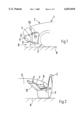
- FIG. 1 is a partial lateral view of a forward area of a passenger car having a front-end-side air guiding device known from the state of the art;
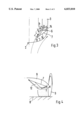
- FIG. 3 is a partial top view of the front-end area of the passenger car with the blow-out opening and the deflection blade;
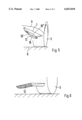
- FIG. 4 is a view corresponding to FIG. 2 of another embodiment of the deflection blade
- FIG. 5 is a view corresponding to FIG. 2 with different alternatives with respect to the cut of the blade edge pointing to the exterior side of the vehicle;
- FIG. 6 is a view corresponding to FIG. 2, in which case, on its rearward end, the deflection blade is combined with a conventional front wheel spoiler.
- the motor vehicle 1 formed by a passenger car has a vehicle body 2 and front wheels 3. Inside the vehicle body 2, a duct-shaped air guiding device 4 for a first air current A is provided inside the vehicle body 2, a duct-shaped air guiding device 4 for a first air current A is provided inside the vehicle body 2, a duct-shaped air guiding device 4 for a first air current A is provided inside the vehicle body 2, a duct-shaped air guiding device 4 for a first air current A is provided inside the vehicle body 2, a duct-shaped air guiding device 4 for a first air current A is provided inside the vehicle body 2, a duct-shaped air guiding device 4 for a first air current A is provided inside the vehicle body 2, a duct-shaped air guiding device 4 for a first air current A is provided inside the vehicle body 2, a duct-shaped air guiding device 4 for a first air current A is provided inside the vehicle body 2, a duct-shaped air guiding device 4 for a first air current A is provided inside the vehicle body 2, a duct
- the vehicle bottom side 6 is provided with an aerodynamically constructed smooth-surface covering part.
- the covering part is formed by a front-end bottom part 9 in the forward area.
- the blow-out openings 7 for the first air current A arranged on the front-end bottom part 9 are provided directly in front of and exclusively in the area of the front wheels 3.
- a device 11 for reducing the flow rate of the first air current A is arranged which is formed by a cooler 10 so that the first air current A behind the blow-out opening 7 has a lower kinetic energy than the second air current B passing through between the vehicle bottom side 7 and the roadway 8.
- a higher pressure level exists in the case of a first air current A than in the case of the second air current B; that is, the first air current A forms an upright, guide-body-type cushion (air wedge) in front of the front wheels 3 around which the second air current B is laterally guided.
- a lift-causing force component F (as illustrated in the case of the state of the art according to FIG. 1) is avoided, it is provided according to the invention that, on the side of the front-end bottom part 6 facing the roadway 8, a deflection blade 12 is arranged in the area of each blow-out opening 7 which deflects the blown-out air current A toward the vehicle side C. As the result of the deflection blade 12, the lift-causing force component is eliminated.
- the occurring impulse of the cooler exhaust air current results in a force component in the downward direction and thus to a reduced front axle lift (see FIG. 2).
- the air-guiding function of the deflection blade 12 which is preferably arranged in parallel to the flow direction equalizes losses in the Cd (drag coefficient) factor which are the result of the fact that the effect of the blow-out current A on the drag cannot be optimally maintained by the deflection.
- the deflection blade 12 is preferably made of a flexible material (such as rubber, plastic or the like and has a relatively thin-walled construction (for example, tin).
- the deflection radius R of the deflection blade 12 should preferably correspond to the height K, in which case the radius should however not be less than 10 mm.
- a blow-out opening 7 is provided which, in the top view, is approximately triangular, the corner points of the blow-out opening in FIG. 3 being marked G, H and J.
- the first boundary edge 13 of the blow-out opening 7, which connects the corner points H and J, is oriented toward the center of the vehicle, whereas the second boundary edge 14 defined by the corner points H and G extends approximately in the transverse direction of the vehicle.
- the third boundary edge 15 extends diagonally from the interior front to the exterior rear and connects the corner points J and G.
- the deflection blade 12 which is preferably arranged in parallel to the locally existing current, is positioned on the boundary edge 13 of the blow-out opening 7 which is oriented toward the vehicle center.
- This deflection blade 12 is at least as long as this edge.
- an exceeding of the width W of the blow-out opening is hardly useful. Starting at approximately half the width of the blow-out opening, the increase of the width results in a rise of the drag. For this reason, it hardly makes any sense to dimension the deflection blade 12 wider than half the width of the blow-out opening.
- the cooling air flow rate will then be limited in a function-impairing manner.
- the leg height which is optimal for a vehicle is a matter of the layout with respect to the requirement of the front axle lift and the still acceptable loss of drag.
- the height K defines the clearance between the front end bottom part 9 and the deflection blade 12.
- the blade height according to FIG. 4 may rise starting in the front at zero to the desired height at the end. This results in only small losses of the aerodynamic capacity.
- the cut of the blade edge pointing to the exterior side of the vehicle if required because of the package (overhang angle), may take place diagonally in a straight line, diagonally convexly or diagonally concavely.
- the three different cuts of the blade edge pointing to the exterior side of the vehicle are marked with the reference numbers 16, 16' and 16".
- the deflection blade 12 may be connected with a conventional front wheel spoiler. This may take place by a mechanical connection or may be shown in one piece. As a result, an advantageous reinforcement of the deflection blade can be achieved.
Abstract
Description
Claims (13)
Applications Claiming Priority (2)
| Application Number | Priority Date | Filing Date | Title |
|---|---|---|---|
| DE19705268A DE19705268C2 (en) | 1997-02-12 | 1997-02-12 | Motor vehicle with an air guiding device on the bow side |
| DE19705268 | 1997-02-12 |
Publications (1)
| Publication Number | Publication Date |
|---|---|
| US6033010A true US6033010A (en) | 2000-03-07 |
Family
ID=7819973
Family Applications (1)
| Application Number | Title | Priority Date | Filing Date |
|---|---|---|---|
| US09/014,166 Expired - Fee Related US6033010A (en) | 1997-02-12 | 1998-01-27 | Air guiding arrangement for a motor vehicle front end |
Country Status (5)
| Country | Link |
|---|---|
| US (1) | US6033010A (en) |
| EP (1) | EP0858944B1 (en) |
| JP (1) | JPH10226369A (en) |
| KR (1) | KR100509315B1 (en) |
| DE (2) | DE19705268C2 (en) |
Cited By (36)
| Publication number | Priority date | Publication date | Assignee | Title |
|---|---|---|---|---|
| US6260911B1 (en) * | 2000-02-16 | 2001-07-17 | John H. Becker | Air duct for cooling rotating tires |
| US6575522B2 (en) * | 2000-12-19 | 2003-06-10 | Ferrari S.P.A. | Vehicle with movable spoilers |
| US20030116996A1 (en) * | 2001-12-11 | 2003-06-26 | Heinz Soja | Motor vehicle having a front end comprising an air-guiding device and method of making and using same |
| US20030173798A1 (en) * | 2000-09-15 | 2003-09-18 | Hartmut Steinicke | Motor vehicle with an under body |
| US6637805B2 (en) * | 2001-10-19 | 2003-10-28 | Clayton B. Rees | Apparatus and method for increasing downward force exerted on a spinning vehicle |
| US20040036320A1 (en) * | 2001-10-19 | 2004-02-26 | Rees Clayton B. | Apparatus and method for increasing downward force exerted on a spinning vehicle |
| US20040155485A1 (en) * | 2000-12-20 | 2004-08-12 | Rudyard Hamnett | Deflector for the air-flow in a motor-vehicle |
| US20050116508A1 (en) * | 2003-12-02 | 2005-06-02 | Dr. Ing. H.C.F. Porsche Ag | Wheel house shell for a motor vehicle |
| US20050121945A1 (en) * | 2003-12-04 | 2005-06-09 | Browne Alan L. | Airflow control devices based on active materials |
| US20050121240A1 (en) * | 2003-12-04 | 2005-06-09 | Aase Jan H. | Airflow control devices based on active materials |
| US20050145455A1 (en) * | 2004-01-05 | 2005-07-07 | Honda Motor Co., Ltd. | Air guide for cooling a vehicle brake assembly |
| US20050194815A1 (en) * | 2003-12-04 | 2005-09-08 | Mc Knight Geoffrey P. | Airflow control devices based on active materials |
| US20050212310A1 (en) * | 2004-03-24 | 2005-09-29 | Viriyapanthu Paul Y | Device for protecting the front chin spoiler of an automobile |
| US20050248146A1 (en) * | 2004-05-06 | 2005-11-10 | Byrne Francis J | Apparatus and method for enhancing tire traction |
| US20060196739A1 (en) * | 2005-03-07 | 2006-09-07 | Istvan Paulik | Cycle brake cooling article |
| WO2007007184A1 (en) | 2005-07-08 | 2007-01-18 | Ferrari S.P.A. | High-performance car with streamline configuration- altering air jets |
| US20070182207A1 (en) * | 2006-01-16 | 2007-08-09 | Hiroyuki Nakaya | Aerodynamic device for vehicle |
| US20080272615A1 (en) * | 2004-11-05 | 2008-11-06 | General Motors Corporation | Airflow control devices based on active materials |
| US20080315622A1 (en) * | 2005-12-27 | 2008-12-25 | Kazunori Oda | Wheel Pant Device For a Vehicle and Control Method Thereof |
| US20090295190A1 (en) * | 2007-08-09 | 2009-12-03 | Kottenstette Ryan J | Aerodynamically activated front skirt for a vehicle |
| US20100327625A1 (en) * | 2009-06-26 | 2010-12-30 | Demetrios Tavlarides | Automotive Air Deflector, and a System Thereof |
| US20110095562A1 (en) * | 2007-10-03 | 2011-04-28 | Toyota Jidosha Kabushiki Kaisha | Vehicle and vehicle substructure |
| US20110148143A1 (en) * | 2009-12-22 | 2011-06-23 | John Ondracek | Extendable and Retractable Spoiler |
| US20120007389A1 (en) * | 2010-07-06 | 2012-01-12 | Hbpo Gmbh | Front-end part of a motor vehicle |
| US20120013146A1 (en) * | 2010-07-16 | 2012-01-19 | Dr. Ing. H.C.F. Porsche Aktiengesellschaft | Air guiding device |
| US8210600B1 (en) * | 2011-01-05 | 2012-07-03 | Ford Global Technologies, Llc | Aerodynamic package for an automotive vehicle |
| US20130257093A1 (en) * | 2012-03-28 | 2013-10-03 | Dr. Ing. H.C. F. Porsche Aktiengesellschaft | Front diffuser for a motor vehicle |
| US20150232138A1 (en) * | 2012-09-21 | 2015-08-20 | Mclaren Automotive Limited | Devices for controlling the downforce generated by a vehicle |
| US20150274224A1 (en) * | 2012-12-11 | 2015-10-01 | Toyota Jidosha Kabushiki Kaisha | Vehicle lower structure |
| CN105228888A (en) * | 2013-04-24 | 2016-01-06 | 丰田自动车株式会社 | Vehicle rectifying device |
| US20160016617A1 (en) * | 2014-07-21 | 2016-01-21 | Dr. Ing. H.C. F. Porsche Aktiengesellschaft | Front of a motor vehicle |
| US9669807B2 (en) * | 2014-12-18 | 2017-06-06 | GM Global Technology Operations LLC | Motor vehicle with ventilated wheel case |
| US10227095B2 (en) * | 2014-08-05 | 2019-03-12 | Jaguar Land Rover Limited | Vehicle aerodynamic apparatus |
| US10450011B2 (en) | 2017-02-24 | 2019-10-22 | Dr. Ing. H.C. F. Porsche Aktiengesellschaft | Motor vehicle with front-end diffuser |
| US10668958B2 (en) | 2014-10-31 | 2020-06-02 | Bayerische Motoren Werke Aktiengesellschaft | Motor vehicle having a front apron having duct-like air-guiding devices |
| US11124249B2 (en) * | 2018-10-31 | 2021-09-21 | Mazda Motor Corporation | Deflector structure of automotive vehicle |
Families Citing this family (5)
| Publication number | Priority date | Publication date | Assignee | Title |
|---|---|---|---|---|
| DE10048531C1 (en) * | 2000-09-30 | 2002-04-25 | Porsche Ag | Cooling air duct for motor vehicles |
| DE102008022626A1 (en) | 2008-05-08 | 2009-11-12 | Daimler Ag | Zone separation device for local separation of zone into warm and cold zones of combustion engine in front end of automobile, has inner lining and outer lining, where outer lining thermally separates engine bearing and wheel bearing |
| DE102015008892A1 (en) * | 2015-07-09 | 2016-03-31 | Daimler Ag | Underbody covering for a motor vehicle, in particular passenger cars |
| FR3044998B1 (en) * | 2015-12-10 | 2018-03-23 | Valeo Systemes Thermiques | AERODYNAMIC DEFLECTOR DEVICE FOR A MOTOR VEHICLE WHEEL |
| CN110300696B (en) * | 2017-02-17 | 2021-10-22 | 本田技研工业株式会社 | Air resistance reducing device for vehicle |
Citations (3)
| Publication number | Priority date | Publication date | Assignee | Title |
|---|---|---|---|---|
| FR2491857A1 (en) * | 1980-10-09 | 1982-04-16 | Mure Guy | Self adhesive car wind deflector - is of soft plastics with moulded aluminium strips retained by double face self adhesive |
| EP0213387A2 (en) * | 1985-08-27 | 1987-03-11 | Dr.Ing.h.c. F. Porsche Aktiengesellschaft | Vehicle with an air guiding device on the side of the coachwork |
| DE3542376A1 (en) * | 1985-11-30 | 1987-06-04 | Porsche Ag | MOTOR VEHICLE WITH A BENDING PART THAT IS NEAR A ROAD |
-
1997
- 1997-02-12 DE DE19705268A patent/DE19705268C2/en not_active Expired - Fee Related
- 1997-12-18 EP EP97122370A patent/EP0858944B1/en not_active Expired - Lifetime
- 1997-12-18 DE DE59704784T patent/DE59704784D1/en not_active Expired - Lifetime
-
1998
- 1998-01-27 US US09/014,166 patent/US6033010A/en not_active Expired - Fee Related
- 1998-02-09 JP JP10027381A patent/JPH10226369A/en active Pending
- 1998-02-11 KR KR10-1998-0004022A patent/KR100509315B1/en not_active IP Right Cessation
Patent Citations (5)
| Publication number | Priority date | Publication date | Assignee | Title |
|---|---|---|---|---|
| FR2491857A1 (en) * | 1980-10-09 | 1982-04-16 | Mure Guy | Self adhesive car wind deflector - is of soft plastics with moulded aluminium strips retained by double face self adhesive |
| EP0213387A2 (en) * | 1985-08-27 | 1987-03-11 | Dr.Ing.h.c. F. Porsche Aktiengesellschaft | Vehicle with an air guiding device on the side of the coachwork |
| US4673206A (en) * | 1985-08-27 | 1987-06-16 | Dr. Ing. H.C.F. Porsche Aktiengesellschaft | Motor vehicle with an air guidance device arranged in the body |
| DE3542376A1 (en) * | 1985-11-30 | 1987-06-04 | Porsche Ag | MOTOR VEHICLE WITH A BENDING PART THAT IS NEAR A ROAD |
| US4810021A (en) * | 1985-11-30 | 1989-03-07 | Dr.-Ing H.C.F. Porsche Aktiengesellschaft | Aerodynamic brake cooling spoiler |
Cited By (74)
| Publication number | Priority date | Publication date | Assignee | Title |
|---|---|---|---|---|
| US6260911B1 (en) * | 2000-02-16 | 2001-07-17 | John H. Becker | Air duct for cooling rotating tires |
| US20030173798A1 (en) * | 2000-09-15 | 2003-09-18 | Hartmut Steinicke | Motor vehicle with an under body |
| US6719359B2 (en) * | 2000-09-15 | 2004-04-13 | Audi Ag | Motor vehicle with an under body |
| US6575522B2 (en) * | 2000-12-19 | 2003-06-10 | Ferrari S.P.A. | Vehicle with movable spoilers |
| US20040155485A1 (en) * | 2000-12-20 | 2004-08-12 | Rudyard Hamnett | Deflector for the air-flow in a motor-vehicle |
| US6637805B2 (en) * | 2001-10-19 | 2003-10-28 | Clayton B. Rees | Apparatus and method for increasing downward force exerted on a spinning vehicle |
| US20040036320A1 (en) * | 2001-10-19 | 2004-02-26 | Rees Clayton B. | Apparatus and method for increasing downward force exerted on a spinning vehicle |
| US6742831B2 (en) | 2001-10-19 | 2004-06-01 | Clayton B. Rees | Apparatus and method for increasing downward force exerted on a spinning vehicle |
| US7040690B2 (en) * | 2001-12-11 | 2006-05-09 | Dr. Ing H.C.F. Porsche Ag | Motor vehicle having a front end comprising an air-guiding device and method of making and using same |
| US20030116996A1 (en) * | 2001-12-11 | 2003-06-26 | Heinz Soja | Motor vehicle having a front end comprising an air-guiding device and method of making and using same |
| US20050116508A1 (en) * | 2003-12-02 | 2005-06-02 | Dr. Ing. H.C.F. Porsche Ag | Wheel house shell for a motor vehicle |
| US7086692B2 (en) * | 2003-12-02 | 2006-08-08 | Dr. Ing. H.C.F. Porsche Aktiengesellschaft | Wheel house shell for a motor vehicle |
| US7118652B2 (en) * | 2003-12-04 | 2006-10-10 | General Motors Corporation | Airflow control devices based on active materials |
| US20050121240A1 (en) * | 2003-12-04 | 2005-06-09 | Aase Jan H. | Airflow control devices based on active materials |
| US7429074B2 (en) | 2003-12-04 | 2008-09-30 | General Motors Corporation | Airflow control devices based on active materials |
| US20050230546A1 (en) * | 2003-12-04 | 2005-10-20 | Mc Knight Geoffrey P | Airflow control devices based on active materials |
| US7178859B2 (en) * | 2003-12-04 | 2007-02-20 | General Motors Corporation | Method for controlling airflow |
| US6979050B2 (en) * | 2003-12-04 | 2005-12-27 | General Motors Corporation | Airflow control devices based on active materials |
| US20060049666A1 (en) * | 2003-12-04 | 2006-03-09 | General Motors Corporation | Airflow control devices based on active materials |
| US20050121945A1 (en) * | 2003-12-04 | 2005-06-09 | Browne Alan L. | Airflow control devices based on active materials |
| US7059664B2 (en) | 2003-12-04 | 2006-06-13 | General Motors Corporation | Airflow control devices based on active materials |
| US20050194815A1 (en) * | 2003-12-04 | 2005-09-08 | Mc Knight Geoffrey P. | Airflow control devices based on active materials |
| US7703839B2 (en) | 2003-12-04 | 2010-04-27 | Gm Global Technology Operations, Inc. | Airflow control devices based on active materials |
| US20060214469A1 (en) * | 2003-12-04 | 2006-09-28 | General Motors Corporation | Airflow control devices based on active materials |
| US7147271B2 (en) | 2003-12-04 | 2006-12-12 | General Motors Corporation | Airflow control devices with planar surfaces |
| US20060267376A1 (en) * | 2003-12-04 | 2006-11-30 | Mcknight Geoffrey P | Airflow control devices based on active materials |
| US7147269B2 (en) | 2003-12-04 | 2006-12-12 | General Motors Corporation | Airflow control devices using current |
| US20050145455A1 (en) * | 2004-01-05 | 2005-07-07 | Honda Motor Co., Ltd. | Air guide for cooling a vehicle brake assembly |
| US7198139B2 (en) * | 2004-01-05 | 2007-04-03 | Honda Motor Co., Ltd. | Air guide for cooling a vehicle brake assembly |
| US20050212310A1 (en) * | 2004-03-24 | 2005-09-29 | Viriyapanthu Paul Y | Device for protecting the front chin spoiler of an automobile |
| US7370888B2 (en) | 2004-05-06 | 2008-05-13 | Bridgestone Firestone North American Tire, Llc | Apparatus and method for enhancing tire traction |
| US20050248146A1 (en) * | 2004-05-06 | 2005-11-10 | Byrne Francis J | Apparatus and method for enhancing tire traction |
| US20080272615A1 (en) * | 2004-11-05 | 2008-11-06 | General Motors Corporation | Airflow control devices based on active materials |
| US7854467B2 (en) | 2004-11-05 | 2010-12-21 | General Motors Corporation | Airflow control devices based on active materials |
| US20060196739A1 (en) * | 2005-03-07 | 2006-09-07 | Istvan Paulik | Cycle brake cooling article |
| US7337884B2 (en) * | 2005-03-07 | 2008-03-04 | Vented Brakes, Inc. | Cycle brake cooling article |
| WO2007007184A1 (en) | 2005-07-08 | 2007-01-18 | Ferrari S.P.A. | High-performance car with streamline configuration- altering air jets |
| US7886859B2 (en) | 2005-07-08 | 2011-02-15 | Ferrari S.P.A. | High-performance car with streamline configuration-altering air jets |
| US20080315622A1 (en) * | 2005-12-27 | 2008-12-25 | Kazunori Oda | Wheel Pant Device For a Vehicle and Control Method Thereof |
| US7988220B2 (en) * | 2005-12-27 | 2011-08-02 | Toyota Jidosha Kabushiki Kaisha | Wheel pant device for a vehicle and control method thereof |
| US20070182207A1 (en) * | 2006-01-16 | 2007-08-09 | Hiroyuki Nakaya | Aerodynamic device for vehicle |
| US7380869B2 (en) * | 2006-01-16 | 2008-06-03 | Toyota Jidosha Kabushiki Kaisha | Aerodynamic device for vehicle |
| US20090295190A1 (en) * | 2007-08-09 | 2009-12-03 | Kottenstette Ryan J | Aerodynamically activated front skirt for a vehicle |
| US7780223B2 (en) * | 2007-08-09 | 2010-08-24 | Bayerische Motoren Werke Aktiengesellschaft | Aerodynamically activated front skirt for a vehicle |
| US20110095562A1 (en) * | 2007-10-03 | 2011-04-28 | Toyota Jidosha Kabushiki Kaisha | Vehicle and vehicle substructure |
| US8366178B2 (en) * | 2007-10-03 | 2013-02-05 | Toyota Jidosha Kabushiki Kaisha | Vehicle and vehicle substructure |
| US8246103B2 (en) * | 2009-06-26 | 2012-08-21 | Demetrios Tavlarides | Automotive air deflector, and a system thereof |
| US20100327625A1 (en) * | 2009-06-26 | 2010-12-30 | Demetrios Tavlarides | Automotive Air Deflector, and a System Thereof |
| US8308222B2 (en) | 2009-12-22 | 2012-11-13 | John Ondracek | Extendable and retractable spoiler |
| US20110148143A1 (en) * | 2009-12-22 | 2011-06-23 | John Ondracek | Extendable and Retractable Spoiler |
| US20120007389A1 (en) * | 2010-07-06 | 2012-01-12 | Hbpo Gmbh | Front-end part of a motor vehicle |
| US8491050B2 (en) * | 2010-07-06 | 2013-07-23 | Dr. Ing. H.C.F. Porsche Aktiengesellschaft | Front-end part of a motor vehicle |
| CN102336226A (en) * | 2010-07-16 | 2012-02-01 | F·波尔希名誉工学博士公司 | Air guiding device |
| US20120013146A1 (en) * | 2010-07-16 | 2012-01-19 | Dr. Ing. H.C.F. Porsche Aktiengesellschaft | Air guiding device |
| US8297685B2 (en) * | 2010-07-16 | 2012-10-30 | Dr. Ing. H.C.F. Porsche Aktiengesellschaft | Air guiding device |
| CN102336226B (en) * | 2010-07-16 | 2015-08-19 | F·波尔希名誉工学博士公司 | Air guiding device |
| US8210600B1 (en) * | 2011-01-05 | 2012-07-03 | Ford Global Technologies, Llc | Aerodynamic package for an automotive vehicle |
| US20130257093A1 (en) * | 2012-03-28 | 2013-10-03 | Dr. Ing. H.C. F. Porsche Aktiengesellschaft | Front diffuser for a motor vehicle |
| US8926000B2 (en) * | 2012-03-28 | 2015-01-06 | Dr. Ing. H.C.F. Porsche Aktiengesellschaft | Front diffuser for a motor vehicle |
| US10099731B2 (en) * | 2012-09-21 | 2018-10-16 | Mclaren Automotive Limited | Devices for controlling the downforce generated by a vehicle during cornering |
| US20150232138A1 (en) * | 2012-09-21 | 2015-08-20 | Mclaren Automotive Limited | Devices for controlling the downforce generated by a vehicle |
| US10752303B2 (en) * | 2012-09-21 | 2020-08-25 | Mclaren Automotive Limited | Component for controlling downforce generated by a vehicle |
| US9561827B2 (en) * | 2012-09-21 | 2017-02-07 | McLaren Technology Centre | Devices for controlling the downforce generated by a vehicle |
| US10106211B2 (en) * | 2012-09-21 | 2018-10-23 | Mclaren Automotive Limited | Adjustable component cooling device for controlling downforce generated by a vehicle |
| US9352792B2 (en) * | 2012-12-11 | 2016-05-31 | Toyota Jidosha Kabushiki Kaisha | Vehicle lower structure |
| US20150274224A1 (en) * | 2012-12-11 | 2015-10-01 | Toyota Jidosha Kabushiki Kaisha | Vehicle lower structure |
| CN105228888A (en) * | 2013-04-24 | 2016-01-06 | 丰田自动车株式会社 | Vehicle rectifying device |
| US9694858B2 (en) * | 2014-07-21 | 2017-07-04 | Dr. Ing. H.C. F. Porsche Aktiengesellschaft | Front of a motor vehicle |
| US20160016617A1 (en) * | 2014-07-21 | 2016-01-21 | Dr. Ing. H.C. F. Porsche Aktiengesellschaft | Front of a motor vehicle |
| US10227095B2 (en) * | 2014-08-05 | 2019-03-12 | Jaguar Land Rover Limited | Vehicle aerodynamic apparatus |
| US10668958B2 (en) | 2014-10-31 | 2020-06-02 | Bayerische Motoren Werke Aktiengesellschaft | Motor vehicle having a front apron having duct-like air-guiding devices |
| US9669807B2 (en) * | 2014-12-18 | 2017-06-06 | GM Global Technology Operations LLC | Motor vehicle with ventilated wheel case |
| US10450011B2 (en) | 2017-02-24 | 2019-10-22 | Dr. Ing. H.C. F. Porsche Aktiengesellschaft | Motor vehicle with front-end diffuser |
| US11124249B2 (en) * | 2018-10-31 | 2021-09-21 | Mazda Motor Corporation | Deflector structure of automotive vehicle |
Also Published As
| Publication number | Publication date |
|---|---|
| DE19705268A1 (en) | 1998-08-13 |
| KR100509315B1 (en) | 2005-10-24 |
| KR19980071261A (en) | 1998-10-26 |
| DE59704784D1 (en) | 2001-11-08 |
| EP0858944A1 (en) | 1998-08-19 |
| JPH10226369A (en) | 1998-08-25 |
| EP0858944B1 (en) | 2001-10-04 |
| DE19705268C2 (en) | 1999-10-21 |
Similar Documents
| Publication | Publication Date | Title |
|---|---|---|
| US6033010A (en) | Air guiding arrangement for a motor vehicle front end | |
| US4460213A (en) | Motor vehicle front end with an adjustable airflow device | |
| US4379582A (en) | Device for improving aerodynamic and safety characteristics of automotive vehicles | |
| US4772060A (en) | Air guide arrangement for the underside of a vehicle | |
| US6669270B1 (en) | Truck wind deflector | |
| US5511847A (en) | Front end covering for a motor vehicle | |
| JP4903352B2 (en) | Car with lower body | |
| US7695050B2 (en) | Vehicle having aerodynamic fan elements | |
| US10933927B2 (en) | Airflow deflector for a vehicle | |
| KR101319056B1 (en) | Vehicle boundary layer air flow control structure | |
| US20220355871A1 (en) | Vehicle | |
| US6343401B1 (en) | Wiper blade with wind deflector | |
| US20040155485A1 (en) | Deflector for the air-flow in a motor-vehicle | |
| US5934740A (en) | Air guiding device | |
| JP2001180530A (en) | Fender liner for automobile | |
| JP2689608B2 (en) | Midship car | |
| JP2002120769A (en) | Vehicle body structure | |
| EP0420826A1 (en) | A system for reducing slipstream drag for high-performance motor cars | |
| US5927795A (en) | Vehicle aerodynamic stability device | |
| JP4631566B2 (en) | Auto body structure | |
| JPH04339079A (en) | Device for improving aerodynamic characteristic of car | |
| CN110294027B (en) | Bottom channel vortex generator | |
| JPH06344956A (en) | Traveling stabilizing device for vehicle | |
| JPH0569861A (en) | Front part structure for automobile | |
| JP7164511B2 (en) | Wheel house structure and vehicle |
Legal Events
| Date | Code | Title | Description |
|---|---|---|---|
| AS | Assignment |
Owner name: DR. ING. H.C.F. PORSCHE AG, GERMANY Free format text: ASSIGNMENT OF ASSIGNORS INTEREST;ASSIGNOR:PREISS, MICHAEL;REEL/FRAME:008980/0044 Effective date: 19980116 |
|
| FPAY | Fee payment |
Year of fee payment: 4 |
|
| FPAY | Fee payment |
Year of fee payment: 8 |
|
| AS | Assignment |
Owner name: DR. ING. H.C.F. PORSCHE AKTIENGESELLSCHAFT (COMPAN Free format text: MERGER;ASSIGNOR:DR. ING. H.C.F. PORSCHE AKTIENGESELLSCHAFT (COMPANY NUMBER 5211);REEL/FRAME:021040/0147 Effective date: 20071113 |
|
| AS | Assignment |
Owner name: DR. ING. H.C.F. PORSCHE AKTIENGESELLSCHAFT, GERMAN Free format text: CHANGE OF NAME;ASSIGNOR:PORSCHE ZWISCHENHOLDING GMBH;REEL/FRAME:025227/0747 Effective date: 20091130 Owner name: PORSCHE ZWISCHENHOLDING GMBH, GERMANY Free format text: MERGER;ASSIGNOR:DR. ING. H.C.F. PORSCHE AKTIENGESELLSCHAFT;REEL/FRAME:025227/0699 Effective date: 20091125 |
|
| REMI | Maintenance fee reminder mailed | ||
| LAPS | Lapse for failure to pay maintenance fees | ||
| STCH | Information on status: patent discontinuation |
Free format text: PATENT EXPIRED DUE TO NONPAYMENT OF MAINTENANCE FEES UNDER 37 CFR 1.362 |
|
| FP | Lapsed due to failure to pay maintenance fee |
Effective date: 20120307 |