US5798631A - Performance optimization controller and control method for doubly-fed machines - Google Patents
Performance optimization controller and control method for doubly-fed machines Download PDFInfo
- Publication number
- US5798631A US5798631A US08/725,187 US72518796A US5798631A US 5798631 A US5798631 A US 5798631A US 72518796 A US72518796 A US 72518796A US 5798631 A US5798631 A US 5798631A
- Authority
- US
- United States
- Prior art keywords
- power
- converter
- control winding
- doubly
- frequency
- Prior art date
- Legal status (The legal status is an assumption and is not a legal conclusion. Google has not performed a legal analysis and makes no representation as to the accuracy of the status listed.)
- Expired - Fee Related
Links
- 238000000034 method Methods 0.000 title claims description 22
- 238000005457 optimization Methods 0.000 title description 8
- 238000004804 winding Methods 0.000 claims abstract description 105
- 230000005284 excitation Effects 0.000 claims description 14
- 230000001276 controlling effect Effects 0.000 claims description 12
- 230000001105 regulatory effect Effects 0.000 claims description 7
- 238000001914 filtration Methods 0.000 claims description 5
- 230000011664 signaling Effects 0.000 claims 7
- 230000003044 adaptive effect Effects 0.000 abstract description 23
- 230000003190 augmentative effect Effects 0.000 abstract description 2
- 238000004422 calculation algorithm Methods 0.000 description 44
- 230000006698 induction Effects 0.000 description 23
- 230000001360 synchronised effect Effects 0.000 description 13
- 238000004146 energy storage Methods 0.000 description 10
- 238000010586 diagram Methods 0.000 description 9
- 238000005259 measurement Methods 0.000 description 9
- 230000008901 benefit Effects 0.000 description 7
- 238000006243 chemical reaction Methods 0.000 description 7
- 238000013461 design Methods 0.000 description 7
- 238000013528 artificial neural network Methods 0.000 description 6
- 230000008569 process Effects 0.000 description 6
- 238000012549 training Methods 0.000 description 6
- 238000013459 approach Methods 0.000 description 5
- 230000033228 biological regulation Effects 0.000 description 4
- 230000008859 change Effects 0.000 description 4
- 239000004065 semiconductor Substances 0.000 description 4
- 238000011217 control strategy Methods 0.000 description 3
- 230000008878 coupling Effects 0.000 description 3
- 238000010168 coupling process Methods 0.000 description 3
- 238000005859 coupling reaction Methods 0.000 description 3
- 230000005611 electricity Effects 0.000 description 3
- 230000003993 interaction Effects 0.000 description 3
- 238000010248 power generation Methods 0.000 description 3
- 238000003860 storage Methods 0.000 description 3
- 230000002457 bidirectional effect Effects 0.000 description 2
- 239000003990 capacitor Substances 0.000 description 2
- 238000010276 construction Methods 0.000 description 2
- 230000007423 decrease Effects 0.000 description 2
- 230000003247 decreasing effect Effects 0.000 description 2
- 238000009826 distribution Methods 0.000 description 2
- 238000005516 engineering process Methods 0.000 description 2
- ZZUFCTLCJUWOSV-UHFFFAOYSA-N furosemide Chemical compound C1=C(Cl)C(S(=O)(=O)N)=CC(C(O)=O)=C1NCC1=CC=CO1 ZZUFCTLCJUWOSV-UHFFFAOYSA-N 0.000 description 2
- 238000012423 maintenance Methods 0.000 description 2
- 230000010355 oscillation Effects 0.000 description 2
- 230000010349 pulsation Effects 0.000 description 2
- 238000010845 search algorithm Methods 0.000 description 2
- 238000012360 testing method Methods 0.000 description 2
- 238000012546 transfer Methods 0.000 description 2
- XLYOFNOQVPJJNP-UHFFFAOYSA-N water Substances O XLYOFNOQVPJJNP-UHFFFAOYSA-N 0.000 description 2
- RYGMFSIKBFXOCR-UHFFFAOYSA-N Copper Chemical compound [Cu] RYGMFSIKBFXOCR-UHFFFAOYSA-N 0.000 description 1
- CYTYCFOTNPOANT-UHFFFAOYSA-N Perchloroethylene Chemical compound ClC(Cl)=C(Cl)Cl CYTYCFOTNPOANT-UHFFFAOYSA-N 0.000 description 1
- 239000006096 absorbing agent Substances 0.000 description 1
- 230000001668 ameliorated effect Effects 0.000 description 1
- 230000005540 biological transmission Effects 0.000 description 1
- 238000004364 calculation method Methods 0.000 description 1
- 238000012512 characterization method Methods 0.000 description 1
- 230000002860 competitive effect Effects 0.000 description 1
- 239000012141 concentrate Substances 0.000 description 1
- 238000011109 contamination Methods 0.000 description 1
- 229910052802 copper Inorganic materials 0.000 description 1
- 239000010949 copper Substances 0.000 description 1
- 230000001419 dependent effect Effects 0.000 description 1
- 238000001514 detection method Methods 0.000 description 1
- 238000011161 development Methods 0.000 description 1
- 238000006073 displacement reaction Methods 0.000 description 1
- 230000000694 effects Effects 0.000 description 1
- 230000005672 electromagnetic field Effects 0.000 description 1
- 230000007613 environmental effect Effects 0.000 description 1
- 238000000605 extraction Methods 0.000 description 1
- 230000004907 flux Effects 0.000 description 1
- 239000002803 fossil fuel Substances 0.000 description 1
- 238000002347 injection Methods 0.000 description 1
- 239000007924 injection Substances 0.000 description 1
- 230000010354 integration Effects 0.000 description 1
- 238000011835 investigation Methods 0.000 description 1
- 230000005415 magnetization Effects 0.000 description 1
- 238000004519 manufacturing process Methods 0.000 description 1
- 239000000463 material Substances 0.000 description 1
- 230000007246 mechanism Effects 0.000 description 1
- 238000012544 monitoring process Methods 0.000 description 1
- 230000000737 periodic effect Effects 0.000 description 1
- 238000012545 processing Methods 0.000 description 1
- 230000009467 reduction Effects 0.000 description 1
- 230000000717 retained effect Effects 0.000 description 1
- 238000004088 simulation Methods 0.000 description 1
- 238000011144 upstream manufacturing Methods 0.000 description 1
Images


Classifications
-
- F—MECHANICAL ENGINEERING; LIGHTING; HEATING; WEAPONS; BLASTING
- F03—MACHINES OR ENGINES FOR LIQUIDS; WIND, SPRING, OR WEIGHT MOTORS; PRODUCING MECHANICAL POWER OR A REACTIVE PROPULSIVE THRUST, NOT OTHERWISE PROVIDED FOR
- F03D—WIND MOTORS
- F03D7/00—Controlling wind motors
- F03D7/02—Controlling wind motors the wind motors having rotation axis substantially parallel to the air flow entering the rotor
- F03D7/0272—Controlling wind motors the wind motors having rotation axis substantially parallel to the air flow entering the rotor by measures acting on the electrical generator
-
- F—MECHANICAL ENGINEERING; LIGHTING; HEATING; WEAPONS; BLASTING
- F03—MACHINES OR ENGINES FOR LIQUIDS; WIND, SPRING, OR WEIGHT MOTORS; PRODUCING MECHANICAL POWER OR A REACTIVE PROPULSIVE THRUST, NOT OTHERWISE PROVIDED FOR
- F03D—WIND MOTORS
- F03D7/00—Controlling wind motors
- F03D7/02—Controlling wind motors the wind motors having rotation axis substantially parallel to the air flow entering the rotor
- F03D7/04—Automatic control; Regulation
- F03D7/042—Automatic control; Regulation by means of an electrical or electronic controller
- F03D7/043—Automatic control; Regulation by means of an electrical or electronic controller characterised by the type of control logic
- F03D7/046—Automatic control; Regulation by means of an electrical or electronic controller characterised by the type of control logic with learning or adaptive control, e.g. self-tuning, fuzzy logic or neural network
-
- H—ELECTRICITY
- H02—GENERATION; CONVERSION OR DISTRIBUTION OF ELECTRIC POWER
- H02P—CONTROL OR REGULATION OF ELECTRIC MOTORS, ELECTRIC GENERATORS OR DYNAMO-ELECTRIC CONVERTERS; CONTROLLING TRANSFORMERS, REACTORS OR CHOKE COILS
- H02P9/00—Arrangements for controlling electric generators for the purpose of obtaining a desired output
- H02P9/007—Control circuits for doubly fed generators
-
- H—ELECTRICITY
- H02—GENERATION; CONVERSION OR DISTRIBUTION OF ELECTRIC POWER
- H02P—CONTROL OR REGULATION OF ELECTRIC MOTORS, ELECTRIC GENERATORS OR DYNAMO-ELECTRIC CONVERTERS; CONTROLLING TRANSFORMERS, REACTORS OR CHOKE COILS
- H02P9/00—Arrangements for controlling electric generators for the purpose of obtaining a desired output
- H02P9/42—Arrangements for controlling electric generators for the purpose of obtaining a desired output to obtain desired frequency without varying speed of the generator
-
- F—MECHANICAL ENGINEERING; LIGHTING; HEATING; WEAPONS; BLASTING
- F05—INDEXING SCHEMES RELATING TO ENGINES OR PUMPS IN VARIOUS SUBCLASSES OF CLASSES F01-F04
- F05B—INDEXING SCHEME RELATING TO WIND, SPRING, WEIGHT, INERTIA OR LIKE MOTORS, TO MACHINES OR ENGINES FOR LIQUIDS COVERED BY SUBCLASSES F03B, F03D AND F03G
- F05B2210/00—Working fluid
- F05B2210/16—Air or water being indistinctly used as working fluid, i.e. the machine can work equally with air or water without any modification
-
- F—MECHANICAL ENGINEERING; LIGHTING; HEATING; WEAPONS; BLASTING
- F05—INDEXING SCHEMES RELATING TO ENGINES OR PUMPS IN VARIOUS SUBCLASSES OF CLASSES F01-F04
- F05B—INDEXING SCHEME RELATING TO WIND, SPRING, WEIGHT, INERTIA OR LIKE MOTORS, TO MACHINES OR ENGINES FOR LIQUIDS COVERED BY SUBCLASSES F03B, F03D AND F03G
- F05B2270/00—Control
- F05B2270/10—Purpose of the control system
- F05B2270/20—Purpose of the control system to optimise the performance of a machine
-
- H—ELECTRICITY
- H02—GENERATION; CONVERSION OR DISTRIBUTION OF ELECTRIC POWER
- H02P—CONTROL OR REGULATION OF ELECTRIC MOTORS, ELECTRIC GENERATORS OR DYNAMO-ELECTRIC CONVERTERS; CONTROLLING TRANSFORMERS, REACTORS OR CHOKE COILS
- H02P2101/00—Special adaptation of control arrangements for generators
- H02P2101/15—Special adaptation of control arrangements for generators for wind-driven turbines
-
- H—ELECTRICITY
- H02—GENERATION; CONVERSION OR DISTRIBUTION OF ELECTRIC POWER
- H02P—CONTROL OR REGULATION OF ELECTRIC MOTORS, ELECTRIC GENERATORS OR DYNAMO-ELECTRIC CONVERTERS; CONTROLLING TRANSFORMERS, REACTORS OR CHOKE COILS
- H02P2207/00—Indexing scheme relating to controlling arrangements characterised by the type of motor
- H02P2207/07—Doubly fed machines receiving two supplies both on the stator only wherein the power supply is fed to different sets of stator windings or to rotor and stator windings
- H02P2207/073—Doubly fed machines receiving two supplies both on the stator only wherein the power supply is fed to different sets of stator windings or to rotor and stator windings wherein only one converter is used, the other windings being supplied without converter, e.g. doubly-fed induction machines
-
- Y—GENERAL TAGGING OF NEW TECHNOLOGICAL DEVELOPMENTS; GENERAL TAGGING OF CROSS-SECTIONAL TECHNOLOGIES SPANNING OVER SEVERAL SECTIONS OF THE IPC; TECHNICAL SUBJECTS COVERED BY FORMER USPC CROSS-REFERENCE ART COLLECTIONS [XRACs] AND DIGESTS
- Y02—TECHNOLOGIES OR APPLICATIONS FOR MITIGATION OR ADAPTATION AGAINST CLIMATE CHANGE
- Y02E—REDUCTION OF GREENHOUSE GAS [GHG] EMISSIONS, RELATED TO ENERGY GENERATION, TRANSMISSION OR DISTRIBUTION
- Y02E10/00—Energy generation through renewable energy sources
- Y02E10/70—Wind energy
- Y02E10/72—Wind turbines with rotation axis in wind direction
Definitions
- This invention relates to energy conversion systems for generating or consuming electricity and for methods for controlling such systems. More particularly, this invention relates to a control system for optimizing the performance of a doubly-fed variable speed generation (VSG) system such as a wind or hydro turbine-based system or a doubly-fed adjustable speed drive (ASD) system.
- VSG variable speed generation
- ASD doubly-fed adjustable speed drive
- a VSG system converts energy from a variable resource such as wind or water flow into variable rotational mechanical energy of a turbine or other device. The mechanical energy is then converted into electrical energy by an electrical generator.
- VSG systems that utilize a doubly-fed electrical generator are shown and described in U.S. Pat. Nos. 4,994,684 and 5,028,804, which are hereby incorporated by reference.
- variable-speed generators Due to the power electronic utility interface provided with a typical variable speed generation systems, it is also possible to improve the poor displacement power factor associated with induction generators. At the same time, harmonics from other generators or non-linear loads can be minimized or compensated using appropriate converter control algorithms and passive harmonic filters. While offering significant benefits in operational performance, variable-speed generators have the drawbacks of higher initial cost as well as increased complexity resulting in potentially lower reliability. In a well designed and engineered system, however, the additional costs should be offset by increased energy capture and improved control flexibility.
- An objective of this invention therefore is to provide a VSG system of simpler design and low initial cost that can be inexpensively maintained on site.
- Another objective of the invention is to provide a VSG system that maximizes the real or active power generated by the system at any given variable resource energy level.
- the proposed variable speed, constant frequency (VSCF) system utilizes a doubly-fed machine (DFM) to maximize the output power of the system.
- the system includes a power converter that provides a current excitation signal to the control winding of the DFM.
- the output of the power converter is controlled by an adaptive controller.
- the controller signals the converter to vary the frequency of its output current excitation signal and thereby the rotor speed of the DFM until a maximum power output is sensed (maximum power point of turbine converting resource energy into mechanical energy).
- the controller also signals the converter to vary the magnitude of the output current excitation signal and thereby the portions of power carried by the respective windings of the DFM until a maximum power output is again sensed (maximum power point of generator system converting mechanical into electrical energy).
- the control can be augmented to not only maximize power and efficiency, but also provide for harmonic and reactive power compensation.
- FIG. 1 is a graph of power available with VSCF/CSCF systems.
- FIG. 2 is a graph of the power coefficient of a 100 kW wind turbine.
- FIG. 3 is a graph of power and speed characteristics of a 100 kW turbine.
- FIGS. 4(a)-(d) are block diagrams of four possible energy conversion systems for VSG: (a) synchronous (b) wound rotor induction (c) cage rotor induction and (d) brushless doubly-fed.
- FIG. 5 is a three dimensional graph of electrical power as a function of control frequency and control current in a VSG system according to the invention.
- FIG. 6 is a block diagram of a VSG system for an electrical generator according to the invention.
- FIG. 7 is a block diagram of an adjustable speed drive (ASD) system for a motor according to the invention.
- ASD adjustable speed drive
- FIG. 8 is a block diagram of a particular embodiment of a brushless doubly-fed VSG system according to the invention.
- FIG. 9 is a block diagram of a control algorithm for a VSG system controller according to the invention.
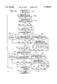
- FIG. 10 is a flowchart of a generalized algorithm for output power maximization according to the invention.
- FIG. 11 is a more detailed version of the algorithm for output power maximization.
- FIG. 12 is a graph of neural network optimum efficiency training data.
- FIG. 13 is a flowchart of an alternative method for finding the maximum power point with respect to turbine speed.
- FIG. 14 is a graph of measured efficiencies of prototype BDFM generator.
- FIG. 15 is a graph of efficiency comparisons.
- FIG. 16 is a diagram of BDFM power gain and converter current.
- FIG. 17 is a graph of annual wind speed distribution.
- FIG. 18 is a graph of measured power enhancement for a BDFM generator according to the invention.
- the invention has applicability in any environment where the energy resource being tapped is varying, such as wind or water.
- the following description therefore, is only of a preferred embodiment of the invention where wind is the resource.
- the invention is not limited to wind-powered systems but may be used wherever its concepts are applicable.
- the conversion of wind energy into electricity on a large scale raises the problem of energy storage.
- the electrical supply grid is a convenient absorber of electricity generated from wind on a large scale, provided the capacity of the wind generation equipment is still small in relation to the total generating capacity coupled to the supply grid. Coupling the wind generating equipment to the supply grid immediately raises the problem of converting the power at varying wind speeds found in practice to the constant frequency of the grid.
- CSCF constant speed constant frequency
- VSCF variable speed constant frequency
- a wind turbine can only extract a certain percentage of the power associated with the wind, up to the maximum Betz limit of 59%. This fraction is described as the power coefficient.
- the value of the power coefficient is a function of the form, wind speed, rotation speed and pitch of the specific wind turbine. Assuming all other operational variables to be constant, this coefficient has only one maximum point at a fixed wind speed as the rotational speed is varied. It is therefore important to adapt the rotational speed of the turbine to correspond to the wind speed in order to extract the maximum power possible out of the wind.
- the characteristics of the power coefficient are normally expressed in terms of the tip-speed-ratio A, which is defined as: ##EQU1## with: v p --tip-speed of turbine blade
- the power coefficient C p is plotted as a function of the tip-speed ratio ⁇ for a 100 kW high speed turbine.
- C p depends on the particulars of blade design and is a function of the tip-speed ratio.
- the torque coefficient C T of the turbine is described in the following equation: ##EQU2## with: ⁇ --air density;
- the power and torque of a wind turbine can be described by the combination of the power, torque and wind speed characteristics shown in FIG. 2. Wind turbines are thus most efficient at one tip-speed ratio ( ⁇ ). As illustrated in FIG. 3, power output is related to the cube of the upstream wind velocity v, or
- variable-speed generation With a fixed-speed wind turbine system, it may be necessary to use pitch control of the blades to optimize performance, thus introducing additional mechanical control systems, complexities and costs. With variable-speed generation, however, it is possible to track the changes in wind speed by changing shaft speed and thus maintaining optimal energy generation.
- FIG. 3 the rotor power from the wind turbine is plotted using variable speed operation (VSG) and fixed speed operation (FSG).
- VSG variable speed operation
- FSG fixed speed operation
- the fixed speed system is optimized at only a single speed, generally representing maximum energy capture potential for a given site, and power output at near cut-in and maximum power are significantly lower than for the variable speed system.
- the fixed speed system is inherently power limited as increasing wind speeds lower the turbine power coefficient.
- the variable speed system will attempt to track maximum power at any wind speed.
- wind and rotor speed are related linearly, whereas in the constant power regime, shaft speed drops off sharply and is kept essentially constant thereafter.
- the data in FIG. 3 also gives the basis for required speed range and gearbox ratio, which relates turbine rotor speed to generator shaft speed.
- Some large wind systems are not self-starting or self-stopping. Tower resonances require that the wind turbine be motored up to the operating speed. Fixed-speed systems require the starting of a large induction machine with the resulting expense of soft start mechanisms; also, stopping a fixed-speed system usually requires a large mechanical braking system.
- CSCF CSCF
- the electromechanical energy conversion is done by means of a synchronous generator so that variations in wind speed have to be accommodated by pitch control of the wind turbine itself.
- pitch control of the wind turbine This means that the primary power flow control function is referred to the mechanical side of the system.
- the wind turbine operates at variable speed. If this variable speed region is made large enough, it is possible to operate a fixed pitch wind turbine and refer the entire power control function to electrical devices.
- variable speed operation is possible with a conventional induction generator, since the efficiency becomes proportional to speed. This has led to the investigation of over synchronous operation of slip ring or wound rotor doubly-fed induction generators with rotor and stator power fed back to the supply. In this case, variable speed operation is possible while only controlling the electrical side of the system.
- These systems are suitable for application to conventional horizontal-axis wind turbines as well as to vertical axis machines.
- FIGS. 4(a)-(d) show variable speed systems based on ac machines and voltage source inverter technology. These represent the desired implementation for medium power (approx. 100-500 kW) wind systems. Higher power turbines may still utilize current-fed, supply commutated topologies.
- the system selection process should be based on the following criteria:
- FIGS. 4(a) and (c) will have approximately the same supply interaction, since all rely on processing the entire power generated in the inverter systems provided with attendant power quality problems.
- the topologies shown in FIGS. 4(b) and (d) generate most power directly into the grid without power electronic interface and thus have potentially more attractive harmonic characteristics.
- Very important differences between the systems lie in the application of selection criteria (i) and (iii) above. Maintenance and reliability considerations, especially for equipment that should be capable of working unattended for extended periods, suggest that slip rings should be avoided.
- the generator system shown in FIG. 4(c) uses a standard cage rotor induction machine (CRIM), of lower cost than the doubly-fed Scherbius cascade. While speed range is not limited to over synchronous operation in this case, the power converters have to be rated for the total power flow, similar to FIG. 4(a). Thus, the advantages of variable-speed generation are achieved, at the expense of significantly increased cost, size and weight due to the rating of the power electronic converter at greater than 100% of induction generator apparent power. This leads to very complex mechanical designs involving multiple induction generators and converters on the same turbine shaft.
- CRIM cage rotor induction machine
- the invention While also applicable to the doubly-fed system shown in FIG. 4(b), the invention utilizes a brushless doubly-fed machine as illustrated in FIG. 4(d).
- the invention uniquely combines the advantages of the cage rotor systems (low machine cost, robust brushless machine construction) with the benefits of the electronic Scherbius configuration (reduced power converter rating and cost) in a novel and unobvious manner. Additional benefits of the combination include greatly enhanced control flexibility due to an additional controller degree of freedom.
- the brushless doubly-fed machine in FIG. 4(d) has two stator windings of different pole number to avoid direct transformer coupling.
- the power and control stator windings interact through the rotor which has a cage structure with a number of identical sections corresponding to the sum of the pole pairs of the stator windings.
- the machine exhibits synchronous behavior during which stator frequencies and shaft speed are related by the following equation:
- p refers to the power winding connected directly to the grid and the subscript "c” refers to the control winding connected to the power converter.
- the p p and p c are the pole pair numbers of the stator windings; f p is the utility grid frequency (60 Hz); f r is the shaft speed dictated by the variable-speed generation algorithm; and f c is the required converter output frequency.
- the mechanical MPPT varies the converter output frequency and thus the turbine shaft speed according to Eq. (4).
- the converter output current magnitude can be used to adjust active and reactive powers associated with the two stator winding systems. For a given mechanical input power, this can be used to control power flow in stator windings and power converter and thus maximize efficiency and output power. This has been shown initially with simulation studies and is verified experimentally as described below.
- control frequency f c is the converter output frequency signal that is applied to the control stator winding to control the turbine shaft speed f r .
- control current I c is a current signal applied to the control stator winding to adjust the active and reactive powers associated with the BDFM and the power balance between both windings.
- z axis is plotted the real or active electrical power output by the system.
- a VSG system 18 which is illustrated in FIG. 6 and relies only on electrical feedback parameters of real power (for MPPT) and reactive power (for optional power factor control).
- a VSG system according to the invention includes a doubly-fed machine (DFM) 20 whose shaft is connected to a wind turbine and gearbox (not shown).
- the DFM is an electromechanical device which converts mechanical energy to electrical energy and vice versa.
- the doubly-fed machine can be realized in different ways, such as in a:
- BDFRM Brushless Doubly-Fed Reluctance Machine
- option (i) It has two windings, the power winding with p p poles and the control winding with p c poles.
- the uncontrolled power winding 22 situated on the stator is directly connected to the grid.
- the control winding 24 is also situated on the stator and is connected to an ac/ac power electronic converter 28 which outputs variable voltage and variable frequency.
- the converter would be connected to the rotor via slip rings, while option (iii) also provides for a stator connection).
- Torque production in the BDFM results from the interaction of the stator and rotor electromagnetic fields.
- the wind turbine input power P wt is related to the turbine torque T wt by
- Equation (4) the rotor speed can be varied linearly by adjusting the frequency f c of the control winding through the power converter 28.
- FIG. 6 uses the term "output" for the interface of the converter to the machine and "input” for the interface between the converter and the utility grid. This is for identification purposes only, as the energy flow is bidirectional. For normal VSG operation in the super synchronous mode, energy will flow from the machine through the converter to the grid.
- the power converter includes as its output stage a current controlled converter 28 with output current control.
- the converter 28 generates output currents i sc , i bc and i cc in the DFM control winding P c , which can be controlled to be sinusoidal with a fundamental frequency of f c .
- f c can be determined by the converter with the information of the demanded mechanical speed f r of the DFM rotor and the turbine.
- the reference for the output current magnitude, I c is an input to the converter from an adaptive controller 30.
- a link energy storage device 32 Connected to the input of the converter 28 is a link energy storage device 32.
- This storage device 32 may be a capacitor bank in a voltage source converter or an inductor in a current source converter for topologies that use a dc-link.
- a link In an ac link a combination of passive devices (capacitors and inductors) is used.
- a combination of passive and active devices In yet another form of dc-link realization, a combination of passive and active devices (discrete electronic components like thyristors, IGBTs, MOSFETs, etc.) is used. It is also possible to convert energy from one form of ac to another form of ac, without the need for link energy storage. This is typically done in a direct converter topology.
- the energy stored in the storage device 32 is monitored by a link monitor 34.
- This monitor includes voltage or current sensor(s) to measure the energy in the link for both dc and ac-link topologies.
- the monitoring of the link helps in regulating the link energy to a desired level.
- the desired link energy is determined by the voltage and current ratings of the sensitive active (power semiconductors) and passive devices in the power circuit.
- the information to increase or decrease energy in the link helps determine the net power flow into or out of the power converters 28 and 38 dynamically.
- phase locked loop also included within the VSG system 18 is a phase locked loop (PLL) 36.
- the PLL provides instantaneous frequency and phase information on the grid voltages to an active utility interface controller 38. Periodic oscillations arise if two asynchronous (of different frequencies of excitation) active sources are interfaced with each other. These oscillations render the circuit unstable.
- the input stage of the interface converter 38 is controlled by the PLL in a manner such that its input voltage and current have a fundamental frequency similar to that of the grid on a dynamic basis.
- the PLL can be implemented by the following methods:
- the converter 38 is the active input stage of a bidirectional ac/ac converter with input current control.
- the converter 38 also includes a set of grid interface inductors connected between the electrical grid and the electronic circuit.
- the magnitudes of the input currents i a , i b and i c are determined dynamically from the input/output power flow of the converter with information obtained from the link monitor 34.
- the input currents are controlled to be sinusoidal with a fundamental frequency of f p (information provided by the PLL), the grid frequency, and the frequency of excitation of the DFM power winding. Since both the magnitude and the phase of the input currents of the converter are actively controlled, it is possible to operate the converter with leading and lagging power factors at the input.
- converter resources can also be utilized to control harmonic interference and regulate line voltage.
- these capabilities are subject to the availability of converter resources and are only implemented when the converter resources are not required for the power maximization control.
- the converter resources 28 and 38 are rated to only achieve the power maximization discussed in this invention, the actual converter utilization will depend on the level of resource energy as a function of wind speed (see FIG. 3). At one point, all the converter resources (allowable semiconductor device currents) may be fully utilized. However, at other points, possibly, not all converter resources are required for power maximization, i.e., the maximum semiconductor currents are not reached. Thus, the remaining allowable converter currents can be utilized for alternative control strategies.
- the power maximization algorithm is entirely controlled by converter 28. Converter 38 is not responsible directly for this power optimization, but provides for the suitable energy transfer between converter 28 and the grid via the link 32.
- converter 38 for reactive power control (to provide additional reactive power to the grid), the converter currents in 38 are controlled to be out of phase with respect to the utility grid voltage. This circulates reactive currents through converter 38 resulting in a higher current than in converter 28, which optimizes the generator real power without consideration to the reactive power.
- the converter currents in 38 will be controlled to have, additionally, currents of higher frequency components, also resulting in a higher total current than in converter 28.
- converters 28 and 38 are rated for the maximization algorithm only, the capability to perform alternative controls (reactive power, voltage regulation, harmonic filtering) will be a function of wind speed and the associated available converter current resources in 38. However, it is possible to rate converter 38 different from converter 28 to allow for sufficient current capability for alternative controls at the utility interface without affecting the optimum power control of converter 28.
- the generator 20 is delivering power from the stator winding 22 and control winding 24.
- the power converter 28, link energy storage 32 and the active utility interface converter, 38 control the torque and speed of the generator in order to maximize the power input from the mechanical resource.
- the power converter 28 is controlled by the adaptive maximum power point (MPPT) controller 30.
- MPPT adaptive maximum power point
- the speed of the generator to track the maximum power point of the turbine is controlled by the control winding frequency reference f c .
- the efficiency of the generator is controlled by the control winding current reference I c .
- the adaptive MPPT controller 30 has as input the measured active and reactive output power P and Q. These measurements are determined from the measured line voltages and currents using power transducers 40.
- the adaptive MPPT controller has as output also the required reactive power reference Q* transmitted to the active utility interface converter in order to control the reactive power on the output of the generator system.
- a link energy reference is also transmitted to the active utility interface converter to regulate the link energy storage, using the link monitor unit.
- the active utility interface converter is synchronized with the ac supply using a PLL 36.
- the generator delivers P T , power to the power utility at maximum input power and maximum generator efficiency.
- the P and Q transducers are used to determine the power from measurements of voltage and current.
- the measured value of P is used to maximize the output power with the MPPT control algorithm.
- the reactive power Q is only measured to control the Active utility interface converter and does not affect the efficiency or maximum power point tracking algorithms.
- the real and reactive powers are sensed by a regular power transducer, a standard commercial item.
- the feature to isolate current harmonics from the grid can be implemented in the active utility interface converter 38.
- Algorithms to isolate harmonics are known and can be implemented in parallel with the other algorithms for active power and reactive power control.
- the apparent power rating of the active utility interface converter can be increased to perform these additional features. This principle is based on the fact that a load current is measured and decomposed into several components, i.e., active current component, reactive current component and a distortion current component.
- the reactive and distortion current components can now be inverted and used as references for the active utility interface converter. This will imply that the rating needs to be increased in converter 38 beyond that of converter 28 and beyond that required for real power optimization.
- converter 38 can be controlled separately from and in addition to the real power maximization to provide for reactive power control, voltage regulation and flicker control. There are several ways of accomplishing these goals, and they are not related to the real power maximization algorithm.
- FIG. 7 shows an alternative embodiment of the invention designed for a drive system such as a motor.
- the speed of operation is typically determined by the process or the application.
- the speed of operation is an external input to the converter 28.
- Torque control is achieved through a torque controller, which may or may not be incorporated into the adaptive controller 30.
- the current magnitude command is obtained from the adaptive controller, which minimizes the input power to the DFM while establishing a desired electromagnetic torque.
- the power-current-frequency graph as shown in FIG. 5 of the attached invention disclosure would be different and would have to accommodate the motoring mode of operation.
- the BDFM motor is supplying mechanical power P mech , to the mechanical load.
- the electrical power is supplied from the stator P p (22) and from the control winding P c (24).
- the current controlled converter 28, link energy storage 32 and the active utility interface converter 38 control the torque and speed of the motor.
- the speed is externally controlled using the control winding frequency f c reference.
- the current controlled converter 28 is controlled from the adaptive controller to maximize the motor efficiency using the control winding current I c reference.
- the DFM motor drive draws P T , power from the power utility at a maximum motor efficiency.
- FIG. 8 is a block diagram of a more particular embodiment of the invention. As shown, current control of converters 28 and 38 is achieved by dedicated, low cost microcontrollers while data acquisition, filtering and adaptive control is implemented in a digital signal processor.
- the BDFM generator is delivering power from the stator winding 22 and control winding 24 to the power utility directly and through the converters 28 and 38.
- the power converter 28, link energy storage 32, and the converter 38 control the torque and speed of the generator in order to maximize the power input from the mechanical energy resource.
- the converter 28 is controlled via a current regulating microcontroller 30.
- the digital signal processor (DSP) microcontroller implementing the adaptive maximum power point algorithm, generates the reference frequency and magnitude of current signals for the current regulating microcontroller 48 to regulate.
- the speed of the generator is controlled by the control winding frequency reference f c , while the efficiency of the generator is controlled by the control winding current reference I c .
- control winding currents i sc , i bc , i cc are measured using a current sensor. As is known in the art, two of the three currents could also be sufficient for current regulation.
- the DSP adaptive MPPT microcontroller has as input the measured active and reactive output power P and Q from the P and Q transducer. These measurements are determined from the measured line voltages and currents using power transducers.
- the adaptive MPPT controller has as output also the required reactive power reference Q* transmitted to the converter 38 in order to control the reactive power on the output at the generator system.
- a dc link voltage reference, V dc is also transmitted to the converter 38 to regulate the dc link voltage, using the voltage sense transducer 42.
- the inner loop of the converter 38 is regulating the current output of the converter 38, i a , i b , i c .
- the interface converter 38 is synchronized with the ac supply using the voltage zero-crossing detector.
- the generator delivers P T , power to the power utility at maximum input power and maximum generator efficiency.
- the adaptive controller 30 can also perform reactive power as well as harmonic compensation.
- FIG. 9 illustrates the control algorithm in block diagram form. Based on output power measurement, the adaptive controller 30 sets converter frequency and current magnitude. While currents for optimum efficiency and thus maximum output power could be calculated based on machine parameters, this should be avoided due to the variations of internal parameters such as rotor time constant. Since mechanical power is also not available, an adaptive approach is proposed in the digital signal processor to aid in the determination of the maximum power point as illustrated in FIGS. 5 and 9.
- the adaptive controller discussed here is based on artificial neural networks. This is, however, only one embodiment. Other possible embodiments are 1) the use of other forms of adaptive or intelligent control or 2) the use of mechanical feedbacks, or 3) the determination and use of system parameters.
- the BDFM generator is connected to a wind turbine on the mechanical axis.
- a mechanical power from the wind turbine has a cube relationship to wind speed and a maximum operating point determined by the tip-speed-ratio.
- the BDFM generator is delivering power from the stator winding 22 and control winding 24 to the power utility directly and through the converters 28 and 38.
- the converter 28, link energy storage 32 and converter 38, control the torque and speed of the generator in order to maximize the power input from the wind turbine.
- the converter 28 is controlled by a three dimensional adaptive seeking control algorithm, implementing the adaptive maximum power point algorithm.
- the speed of the generator is controlled by the control winding frequency f c , while the efficiency of the generator is controlled by the control winding current reference I c .
- the control algorithm has an updating function, which updates the optimum current vs power characteristic during operation to account for changes due to environmental factors.
- the output power of the generating system P T is plotted as a function of the control winding current I c , of the BDFM. This update has an input measurement from the output power P T through the power transducer.
- the generating system is interfaced to the power utility via the Converter 38 converting the dc power back into ac power.
- the generator system delivers P T , power to the power utility at maximum input power from the wind turbine and at the maximum BDFM generator efficiency.
- the characteristic current-power function is updated via a simple two layer neural network.
- initial training data are updated on-line and take into account variations due to operating temperature, etc.
- the search algorithm operates on a moving average value of output power representing relatively slow tracking dynamics (approximately one second).
- the MPPT will not track high frequency power disturbances due to wind gusts and tower shadow.
- FIGS. 10 and 11 are flowcharts that illustrate the operation of system 18. The flowcharts are explained with reference to the wind power generation application. It should be noted that the algorithms can be adapted for other generation (diesel) or even motoring systems.
- FIG. 10 shows a general representation of the output power maximization algorithm for a doubly-fed variable speed wind generation system. It should be emphasized that there could be a multitude of implementation methods for the individual blocks of the flowchart. While implementation could, possibly, vary considerably, the basic optimization algorithm would remain the same.
- the algorithm begins by initializing, in 60, the variables P T , which represents the total measured power of the generator system, and f r , the mechanical or the shaft speed of the DFM-turbine system. Typically, upon system startup, these variables would be initialized non-optimally, and solely based upon the wind speed and the generated power thereof at the time of initialization. Measurement of the total output power P T helps in the determination of the optimal control winding current setting, in 62, from the previously stored I c -P T profile. The I C and P T profile is developed during the DFM characterization as explained above and exemplified in FIG. 12. To ensure operation at the maximum power point of the wind turbine, the mechanical speed, f r , is adaptively determined in 64 by controller 30 in FIG. 6.
- control winding current, I C , and P T are used to update the profile as shown in 66 and 68.
- the algorithm repeats with a new measured output power P T after a fixed delay, in 70 timed by an interrupt in the controller.
- FIG. 11 details a simplified realization of the basic algorithm as shown in FIG. 10.
- the mechanical speed, f r , and the total output power P T are initialized, in 101 and 102 respectively, dependent upon the startup conditions.
- the control winding of the doubly-fed machine (DFM) is excited with a current magnitude as determined from the existing I C -P T profile as shown in 103 (see FIG. 9 as well).
- the output power P T could possibly vary too. If the new measured value of output power P T (1) is greater than that of the initial value, then P T (1) is retained as is shown in 104 and 105.
- Determination of the initial optimum control winding current initiates the optimization algorithm of f r as detailed in 106-113.
- the initialized mechanical speed, f r is incremented by a predetermined quantity ⁇ f r .
- This change in the mechanical speed may vary the output power P T and thus the output power, P T (2), as measured in 107.
- the new output power, if determined, in 109, to be greater than the previous P T is saved, in 108, as the latest operating point for maximum output power.
- the process of incrementing the mechanical speed f r is repeated until the latest measured output power P T (2) is determined to be lower than that of the previous iteration. This leads to the next part of the algorithm where the mechanical speed is decreased by a predetermined quantity, ⁇ f r , as shown in 110-113.
- the basic operation of the algorithm in the speed decremental mode is similar to that in the speed incremental mode as detailed above.
- the system is further optimized by fine tuning the optimal control winding current setting, in 114-122.
- the process of varying the control winding current magnitude, I C is similar to the process for varying f r .
- the control winding current is incremented until the maximum power point it attained, while in 119-122 the current is decremented to obtain the maximum power operating point.
- the new operating point, in the I C -P T domain, obtained as detailed above, is updated in the profile, in 123. The update is required due to the continuously varying system parameters caused by changes in temperature, humidity, magnetic properties of the material of the machine, wear and tear, etc.
- the algorithm repeats with a new measured output power P T after a fixed delay, in 124, timed by an interrupt in the controller.
- the maximum power and efficiency tracking algorithm presented uses a perturbation algorithm, which incrementally changes excitation current frequency and magnitude to obtain maximum overall output power (thus maximizing energy extraction from the wind and minimizing electrical losses in the generator/converter system).
- FIG. 13 illustrates an alternative method for determining the maximum power point with respect to f r .
- the algorithm discussed is a possible realization of block 64 in FIG. 10.
- the algorithm would replace blocks 104-113.
- the algorithm 140-158 replaces 104-113 in FIG. 10.
- This method enables a faster search for the maximum power point (M.P.) as compared to the varying shaft speed approach outlined above.
- M.P. maximum power point
- the main control blocks of this novel algorithm are as shown in FIG. 9.
- the total output power, P T is the only sensed quantity (electrical or mechanical) for the MPPT control loop.
- the I C vs P T block of FIG. 9 is detailed in FIG. 12, which shows an example curve determined from a laboratory prototype.
- the optimum control winding current I C with respect to the total output power P T as characterized in FIG. 12 is obtained from maximum efficiency measurements as shown in FIG. 14.
- information regarding the maximum efficiency of the DFM with respect to total output power P T can also be determined easily from FIG. 14.
- this stored information should be updated similar to that of the I C -P T curve.
- C p ( ⁇ ) is a functional representation of the C p vs. ⁇ characteristic of the turbine as shown in FIG. 2, ⁇ is the density of air, R is the turbine radius, and ⁇ T is the rotor speed which can be determined from equation (4).
- update in 158 the optimum power coefficient, used in step 4, in the C p- ⁇ curve.
- the power coefficient of the turbine may have been modified due to the change in parameters of the turbine over time caused by wear and tear.
- the new optimum C p can be determined by using P wt max in 146 (equation (6)) and assuming the wind speed to have remained constant.
- This algorithm is not entirely based on a perturbation approach as the one previously described (blocks 104 to 113 in FIG. 11), but uses perturbation for fine adjustments.
- the above flowcharts discuss the maximization of active or real power from resource to electrical utility grid. As discussed above, this does not leave a degree of freedom to independently generate reactive power. Rather, the machine will draw reactive power required for magnetization at the particular operating point.
- the reactive power feedback, Q, and reactive power set point, Q*, shown in the figures only interact with the converter 38 (FIGS. 6 and 7) at the grid and are separate from and in addition to the real power maximization.
- the real power control is discussed in detail in the flowcharts and sets the in-phase current component of converter 38.
- the reactive power controller only involves converter 38 and provides for an additional out of phase current component of converter 38.
- Output power in the efficiency maximizing scheme (in all the flowcharts) is defined as the real power.
- the output current can be used to either change real power associated with the machine or reactive power, but not both. If it is desirable to maintain a certain reactive power without using converter 38, a compromise can be made between real and reactive powers via current I C . Then for example, we define a performance factor such as the product of
- adaptive controllers that can be implemented to achieve output power maximization for generator operation or input power minimization for motor operation which use any (or combination) of the following:
- the invention includes a DFM system in the form of a generator that is connected to a utility grid.
- the generator is characterized by voltage and current at the interface to grid.
- the converter 28 is controlled such as to maximize the active or real (in-phase) component of the total current at the grid interface. This is the discussed output power maximization using both converter frequency and current.
- the current waveform may be distorted with harmonics. It is possible via controlling the converter 38 to cancel or isolate these harmonics, achieving optimum harmonic performance. This feature requires additionally the injection of currents of higher frequencies than the control frequency used in (i, ii, iii).
- the grid voltage can be disturbed at the point of common coupling due to factors associated with the grid, such as loading, etc.
- This disturbance can be in the form of a lower fundamental (referred to as voltage dip or sag) or a variation in the rms value (called flicker).
- voltage dip or sag a lower fundamental
- flicker a variation in the rms value
- controllers and control methods are limited to the extent that the converter is designed to produce the appropriate range of frequencies and current magnitudes.
- the control winding current I c is used to optimally transfer the mechanical to electrical energy.
- the doubly-fed machine like any ac machine
- both stator windings (22 and 24) produce real power and require reactive power (or produce the latter) as a function of excitation (voltage and current applied to the windings).
- the real powers delivered by the power winding and the control winding (through the converters) to the grid is optimized by the invention.
- the control winding current magnitude is used to change the real and reactive power allocation between windings.
- reactive power is not directly controlled via the machine, i.e. the reactive power associated with the windings will be such that the machine is magnetized properly.
- the following case study compares a BDFM generator with a more conventional VSG system based on a cage rotor induction machine and PWM converter utility interface.
- the study is based on a wind turbine rated at 100 kW, with characteristics as shown earlier in FIGS. 2 and 3.
- the study compares both generation systems for use at a typical wind site on the Oregon coast.
- the brushless doubly-fed generator is based on six and two-pole stator windings and a die-cast "four-pole" rotor geometry in an induction machine frame. It should be noted that this is only an example and that other pole combinations are also possible.
- Machine design and modeling follow established procedures as discussed previously. While copper loss in the BDFM is calculated directly, core and stray load losses are assumed at 200% of a single winding induction machine to account for higher rotor frequencies and increased leakage due to the two winding stator configuration. Table II summarizes some important BDFM VSG parameters. Speed range and power factor considerations lead to the selection of a 75 kVA power converter, which represents 62.5% of the equivalent induction machine converter rating. In both cases the same gearbox is assumed. The control approach as discussed here does not require the use of a gearbox and can also be applied to direct drive systems without a gearbox.
- FIG. 15 compares steady state electrical efficiencies for the two machines and VSG systems when operating with a wind turbine as described by the characteristics in FIGS. 2 and 3.
- the curves are based on shaft to grid performance and do not include mechanical losses due to gearbox or other extraneous equipment.
- Induction machine control is based on established air gap flux control, while BDFM control relies on the optimized algorithm discussed above. Both systems operate over the same speed range, approximately 3:1.
- the BDFM shows comparable efficiencies to the induction machine.
- converter efficiency becomes significant and the reduced rating of the BDFM power electronics enhances system efficiency significantly. It should be noted that in FIGS.
- wind speeds in excess of 28 m/hr correspond to the constant power mode of operation with the resulting sharp drop off in shaft speed of approximately 20%.
- the BDFM system as designed for this example was found to be voltage limited due to the high converter frequencies required (Eq. 4) and not operating truly in the optimum efficiency mode. This can be adjusted by proper design of the doubly-fed machine to better match turbine speed range and grid voltage. The drop in shaft speed in the constant power regime allows improved current control in the BDFM with the resulting increase in efficiency as illustrated.
- FIG. 16 illustrates the BDFM control winding current and also details the additional power generated by the BDFM VSG system when compared with the induction machine system. As shown, converter current increases with speed in the variable speed region and becomes almost constant during constant power operation.
- FIG. 14 illustrates the relationship between electromagnetic energy conversion efficiency and converter current magnitude for a range of mechanical input power values. It is evident that a unique value of current will ensure optimum efficiency and thus maximum electric output power. It should be noted that the efficiency values given are for a non-optimized system based on a BDFM rewound and converted from an induction machine. Thus, results should only be taken as qualitative representations of system capabilities.
- the peaks of the curves in FIG. 14 represent the desired operating values for a wind power control system.
- the raw data in FIG. 14 can not be used as training data for the neural network algorithm. Rather, training data is established by plotting the optimum control winding current values as a function of electrical output power, which is available to the controller as a feedback quantity (see FIGS. 6-9).
- the resulting curve is illustrated in FIG. 12 for the experimental system.
- the maximum efficiency tracking algorithm initially uses this data to establish a current operating point close to the peak efficiency (see FIG. 5). After an on-line efficiency maximum has been determined, the graph is updated by the neural network.
- the laboratory system can also be used to illustrate the enhanced energy capture due to the optimized controller.
- FIG. 18 shows mechanical power as a function of speed for the laboratory generator. Note that the speed range had to be kept low due to a combination of converter voltage limits and mechanical test stand considerations.
- the electrical power curves shown compare the BDFM operating with the optimum control algorithm with a conventional system based on constant current (I c ) or equivalent V/Hz control. It is evident that a significant increase in power output can be achieved, which correlates with the case study shown in FIG. 16.
Abstract
A variable speed, constant frequency (VSCF) system utilizes a doubly-fed machine (DFM) to maximize the output power of the system. The system includes a power converter that provides a frequency signal and a current signal to the DFM. The power converter is controlled by an adaptive controller. The controller signals the converter to vary its frequency signal and thereby the rotor speed of the DFM until a maximum power output is sensed. The controller also signals the converter to vary its current signal and thereby the portions of power carried by the respective windings until a maximum power output is sensed. The control can be augmented to not only maximize power and efficiency, but also provide for harmonic and reactive power compensation.
Description
This application is based on U.S. Provisional Application Serial No. 60/004,790, filed Oct. 2, 1995.
This invention relates to energy conversion systems for generating or consuming electricity and for methods for controlling such systems. More particularly, this invention relates to a control system for optimizing the performance of a doubly-fed variable speed generation (VSG) system such as a wind or hydro turbine-based system or a doubly-fed adjustable speed drive (ASD) system.
A VSG system converts energy from a variable resource such as wind or water flow into variable rotational mechanical energy of a turbine or other device. The mechanical energy is then converted into electrical energy by an electrical generator. VSG systems that utilize a doubly-fed electrical generator are shown and described in U.S. Pat. Nos. 4,994,684 and 5,028,804, which are hereby incorporated by reference.
Renewed interest has been shown in environmentally conscious renewable energy resources such as wind and hydro power generation schemes with the advent of power electronic drives for VSG systems. Presently available and proposed generators include systems based mainly on dc machine, synchronous and induction machine technology as well as reluctance machines. While extracting more energy from the wind, for example, most proposed variable-speed systems suffer a cost disadvantage due to the required rating of the power electronic converter. This cost penalty may eventually render the additional energy capture meaningless. Thus, reducing the cost of the power electronic hardware is essential for variable-speed generating systems to achieve viable and competitive $/kWh ratios when compared to fossil fuel-based generating systems.
Due to the power electronic utility interface provided with a typical variable speed generation systems, it is also possible to improve the poor displacement power factor associated with induction generators. At the same time, harmonics from other generators or non-linear loads can be minimized or compensated using appropriate converter control algorithms and passive harmonic filters. While offering significant benefits in operational performance, variable-speed generators have the drawbacks of higher initial cost as well as increased complexity resulting in potentially lower reliability. In a well designed and engineered system, however, the additional costs should be offset by increased energy capture and improved control flexibility.
An objective of this invention therefore is to provide a VSG system of simpler design and low initial cost that can be inexpensively maintained on site. Another objective of the invention is to provide a VSG system that maximizes the real or active power generated by the system at any given variable resource energy level.
The proposed variable speed, constant frequency (VSCF) system utilizes a doubly-fed machine (DFM) to maximize the output power of the system. The system includes a power converter that provides a current excitation signal to the control winding of the DFM. The output of the power converter is controlled by an adaptive controller. The controller signals the converter to vary the frequency of its output current excitation signal and thereby the rotor speed of the DFM until a maximum power output is sensed (maximum power point of turbine converting resource energy into mechanical energy). The controller also signals the converter to vary the magnitude of the output current excitation signal and thereby the portions of power carried by the respective windings of the DFM until a maximum power output is again sensed (maximum power point of generator system converting mechanical into electrical energy). The control can be augmented to not only maximize power and efficiency, but also provide for harmonic and reactive power compensation.
The foregoing and other objects, features, and advantages of the invention will become more apparent from the following detailed description of a preferred embodiment which proceeds with reference to the accompanying drawings.
FIG. 1 is a graph of power available with VSCF/CSCF systems.
FIG. 2 is a graph of the power coefficient of a 100 kW wind turbine.
FIG. 3 is a graph of power and speed characteristics of a 100 kW turbine.
FIGS. 4(a)-(d) are block diagrams of four possible energy conversion systems for VSG: (a) synchronous (b) wound rotor induction (c) cage rotor induction and (d) brushless doubly-fed.
FIG. 5 is a three dimensional graph of electrical power as a function of control frequency and control current in a VSG system according to the invention.
FIG. 6 is a block diagram of a VSG system for an electrical generator according to the invention.
FIG. 7 is a block diagram of an adjustable speed drive (ASD) system for a motor according to the invention.
FIG. 8 is a block diagram of a particular embodiment of a brushless doubly-fed VSG system according to the invention.
FIG. 9 is a block diagram of a control algorithm for a VSG system controller according to the invention.
FIG. 10 is a flowchart of a generalized algorithm for output power maximization according to the invention.
FIG. 11 is a more detailed version of the algorithm for output power maximization.
FIG. 12 is a graph of neural network optimum efficiency training data.
FIG. 13 is a flowchart of an alternative method for finding the maximum power point with respect to turbine speed.
FIG. 14 is a graph of measured efficiencies of prototype BDFM generator.
FIG. 15 is a graph of efficiency comparisons.
FIG. 16 is a diagram of BDFM power gain and converter current.
FIG. 17 is a graph of annual wind speed distribution.
FIG. 18 is a graph of measured power enhancement for a BDFM generator according to the invention.
The invention has applicability in any environment where the energy resource being tapped is varying, such as wind or water. The following description, therefore, is only of a preferred embodiment of the invention where wind is the resource. Those of skill in the art will appreciate that the invention is not limited to wind-powered systems but may be used wherever its concepts are applicable.
The conversion of wind energy into electricity on a large scale raises the problem of energy storage. Although work is in progress on various other storage systems, the electrical supply grid is a convenient absorber of electricity generated from wind on a large scale, provided the capacity of the wind generation equipment is still small in relation to the total generating capacity coupled to the supply grid. Coupling the wind generating equipment to the supply grid immediately raises the problem of converting the power at varying wind speeds found in practice to the constant frequency of the grid. For constant speed constant frequency (CSCF) systems the energy capture capability per year is much smaller than for variable speed constant frequency (VSCF) systems, which are a particular type of VSG system. This is illustrated in FIG. 1. The invention, as will be described, is an improved VSCF system.
A wind turbine can only extract a certain percentage of the power associated with the wind, up to the maximum Betz limit of 59%. This fraction is described as the power coefficient. The value of the power coefficient is a function of the form, wind speed, rotation speed and pitch of the specific wind turbine. Assuming all other operational variables to be constant, this coefficient has only one maximum point at a fixed wind speed as the rotational speed is varied. It is therefore important to adapt the rotational speed of the turbine to correspond to the wind speed in order to extract the maximum power possible out of the wind. The characteristics of the power coefficient are normally expressed in terms of the tip-speed-ratio A, which is defined as: ##EQU1## with: vp --tip-speed of turbine blade
R--turbine rotor radius,
ΩT --rotational turbine angular velocity;
v--wind speed.
In FIG. 2 the power coefficient Cp is plotted as a function of the tip-speed ratio λ for a 100 kW high speed turbine. Cp depends on the particulars of blade design and is a function of the tip-speed ratio. The torque coefficient CT of the turbine is described in the following equation: ##EQU2## with: ρ--air density;
A--sweep area
The power and torque of a wind turbine can be described by the combination of the power, torque and wind speed characteristics shown in FIG. 2. Wind turbines are thus most efficient at one tip-speed ratio (λ). As illustrated in FIG. 3, power output is related to the cube of the upstream wind velocity v, or
P.sub.w =1/2πρC.sub.p R.sup.2 v.sup.3 (3)
where p is the specific mass of air and Cp is the coefficient of power.
With a fixed-speed wind turbine system, it may be necessary to use pitch control of the blades to optimize performance, thus introducing additional mechanical control systems, complexities and costs. With variable-speed generation, however, it is possible to track the changes in wind speed by changing shaft speed and thus maintaining optimal energy generation.
In FIG. 3 the rotor power from the wind turbine is plotted using variable speed operation (VSG) and fixed speed operation (FSG). The fixed speed system is optimized at only a single speed, generally representing maximum energy capture potential for a given site, and power output at near cut-in and maximum power are significantly lower than for the variable speed system. The fixed speed system is inherently power limited as increasing wind speeds lower the turbine power coefficient. The variable speed system, on the other hand, will attempt to track maximum power at any wind speed. During variable speed operation wind and rotor speed are related linearly, whereas in the constant power regime, shaft speed drops off sharply and is kept essentially constant thereafter. The data in FIG. 3 also gives the basis for required speed range and gearbox ratio, which relates turbine rotor speed to generator shaft speed.
Horizontal axis wind turbines produce a non-constant torque due to tower shadow. As each blade passes the supporting tower, the output torque decreases. Thus, the torque produced by a two-blade wind turbine contains a harmonic at twice the rotational speed. Typically, a fixed-speed system is unable to mitigate this effect in order to improve the quality of the output power. In VSG systems, however, appropriate control of the power electronic converter can minimize torque ripple and thus output power pulsations. The torque ripple control can utilize either the energy storage in the link of the converter or it can utilize the inertia of the generator as energy storage via appropriate (field oriented) control. See, for example, U.S. Pat. No. 5,083,039 or D. Zhou, "Dynamic Control of Brushless Doubly-Fed Machines," Ph.D. Dissertation, Oregon State University, 1995.
Some large wind systems are not self-starting or self-stopping. Tower resonances require that the wind turbine be motored up to the operating speed. Fixed-speed systems require the starting of a large induction machine with the resulting expense of soft start mechanisms; also, stopping a fixed-speed system usually requires a large mechanical braking system.
In CSCF systems the electromechanical energy conversion is done by means of a synchronous generator so that variations in wind speed have to be accommodated by pitch control of the wind turbine itself. This means that the primary power flow control function is referred to the mechanical side of the system. In VSCF systems, such as in the invention, the wind turbine operates at variable speed. If this variable speed region is made large enough, it is possible to operate a fixed pitch wind turbine and refer the entire power control function to electrical devices.
Only limited variable speed operation is possible with a conventional induction generator, since the efficiency becomes proportional to speed. This has led to the investigation of over synchronous operation of slip ring or wound rotor doubly-fed induction generators with rotor and stator power fed back to the supply. In this case, variable speed operation is possible while only controlling the electrical side of the system. These systems are suitable for application to conventional horizontal-axis wind turbines as well as to vertical axis machines.
Singly-fed cage rotor IM systems inherently use large and expensive converters, typically at 125% of machine rating. Doubly-fed wound-rotor induction generators use much smaller and thus cheaper converters to process slip power, but are more prone to failures due to the use of slip rings. Recently, doubly-fed machines without slip-rings have been proposed as viable variable speed generators for wind power applications. FIGS. 4(a)-(d) show variable speed systems based on ac machines and voltage source inverter technology. These represent the desired implementation for medium power (approx. 100-500 kW) wind systems. Higher power turbines may still utilize current-fed, supply commutated topologies. The system selection process should be based on the following criteria:
(i) Reliability and maintenance;
(ii) Minimum number of components and cost;
(iii) Efficiency and applicability over power range;
(iv) Supply interaction and contamination.
The systems suggested in FIGS. 4(a) and (c) will have approximately the same supply interaction, since all rely on processing the entire power generated in the inverter systems provided with attendant power quality problems. Similarly, the topologies shown in FIGS. 4(b) and (d) generate most power directly into the grid without power electronic interface and thus have potentially more attractive harmonic characteristics. Very important differences between the systems lie in the application of selection criteria (i) and (iii) above. Maintenance and reliability considerations, especially for equipment that should be capable of working unattended for extended periods, suggest that slip rings should be avoided.
Regarding selection criterion (ii) stated above, there is an important fundamental difference between the systems illustrated. In the doubly-fed systems shown, the power electronics do not handle all the system power, but only the part that is used for system control and not directly fed into the supply. Power flow characteristics of the electronic Scherbius system of FIG. 4(b) are well known. The maximum power operation (FIG. 3) corresponds to rated torque at twice synchronous speed, which is the speed of operation with a dc excitation on the control winding, and the power electronic sub-system will be rated at 50% of that necessary for the synchronous generator system in the same application. Thus, doubly-fed systems can be installed at an appreciable saving in capital investment.
The generator system shown in FIG. 4(c), uses a standard cage rotor induction machine (CRIM), of lower cost than the doubly-fed Scherbius cascade. While speed range is not limited to over synchronous operation in this case, the power converters have to be rated for the total power flow, similar to FIG. 4(a). Thus, the advantages of variable-speed generation are achieved, at the expense of significantly increased cost, size and weight due to the rating of the power electronic converter at greater than 100% of induction generator apparent power. This leads to very complex mechanical designs involving multiple induction generators and converters on the same turbine shaft.
While also applicable to the doubly-fed system shown in FIG. 4(b), the invention utilizes a brushless doubly-fed machine as illustrated in FIG. 4(d). The invention uniquely combines the advantages of the cage rotor systems (low machine cost, robust brushless machine construction) with the benefits of the electronic Scherbius configuration (reduced power converter rating and cost) in a novel and unobvious manner. Additional benefits of the combination include greatly enhanced control flexibility due to an additional controller degree of freedom.
The brushless doubly-fed machine in FIG. 4(d) has two stator windings of different pole number to avoid direct transformer coupling. The power and control stator windings interact through the rotor which has a cage structure with a number of identical sections corresponding to the sum of the pole pairs of the stator windings. The machine exhibits synchronous behavior during which stator frequencies and shaft speed are related by the following equation:
f.sub.c =f.sub.r (p.sub.p +p.sub.c)±f.sub.p (4)
where the subscript "p" refers to the power winding connected directly to the grid and the subscript "c" refers to the control winding connected to the power converter. The pp and pc are the pole pair numbers of the stator windings; fp is the utility grid frequency (60 Hz); fr is the shaft speed dictated by the variable-speed generation algorithm; and fc is the required converter output frequency.
Only a fraction of the generator power is processed electronically, resulting in reduced size and cost as well as improved power quality. The die-castable rotor cage ensures robust and inexpensive machine construction.
From FIGS. 2 and 3 it is clear that in order to obtain maximum power from the wind turbine it is necessary to keep the tip-speed-ratio λ constant over a wide range of wind speeds. This is achieved by a maximum power point tracking (MPPT) system which tracks the optimum tip speed ratio for large variations of wind speeds. As wind speed varies, this involves appropriate control of generator shaft speed to ensure that the maximum turbine power is tracked, as illustrated in FIG. 3.
In a doubly-fed machine, the mechanical MPPT varies the converter output frequency and thus the turbine shaft speed according to Eq. (4). At an established shaft speed fr, stable operation is possible for a variety of control winding current levels, thus allowing for an additional degree of control freedom not present in singly-fed systems. The converter output current magnitude can be used to adjust active and reactive powers associated with the two stator winding systems. For a given mechanical input power, this can be used to control power flow in stator windings and power converter and thus maximize efficiency and output power. This has been shown initially with simulation studies and is verified experimentally as described below. Thus, the overall optimization problem for the mechanical (turbine) and electrical (generator) systems involves finding the maximum of power output as a function of (1) turbine shaft speed and (2) control current, as illustrated conceptually in FIG. 5. On the x axis of the graph of FIG. 5 is plotted control frequency fc, which is the converter output frequency signal that is applied to the control stator winding to control the turbine shaft speed fr. On the y axis is plotted a control current Ic, which is a current signal applied to the control stator winding to adjust the active and reactive powers associated with the BDFM and the power balance between both windings. On the z axis is plotted the real or active electrical power output by the system.
To keep the controller of the system simple, mechanically robust and inexpensive, no mechanical inputs such as shaft torque should be required for the control algorithm. This has lead to the development of a VSG system 18 according to the invention which is illustrated in FIG. 6 and relies only on electrical feedback parameters of real power (for MPPT) and reactive power (for optional power factor control). Starting at the left of the figure, a VSG system according to the invention includes a doubly-fed machine (DFM) 20 whose shaft is connected to a wind turbine and gearbox (not shown). The DFM is an electromechanical device which converts mechanical energy to electrical energy and vice versa. The doubly-fed machine can be realized in different ways, such as in a:
(i) Brushless Doubly-Fed Machine (BDFM) with a modified cage rotor;
(ii) Wound Rotor Doubly-Fed Machine (WRDFM) with slip ring rotor connection; or
(iii) Brushless Doubly-Fed Reluctance Machine (BDFRM) with windingless reluctance rotor.
The machine pursued in detail to illustrate the capabilities of the invention is option (i). It has two windings, the power winding with pp poles and the control winding with pc poles. The uncontrolled power winding 22 situated on the stator is directly connected to the grid. The control winding 24 is also situated on the stator and is connected to an ac/ac power electronic converter 28 which outputs variable voltage and variable frequency. (In option (ii) the converter would be connected to the rotor via slip rings, while option (iii) also provides for a stator connection). Torque production in the BDFM results from the interaction of the stator and rotor electromagnetic fields.
For a generator application, the wind turbine input power Pwt is related to the turbine torque Twt by
P.sub.wt =T.sub.wt f.sub.r (5)
where fr is the DFM rotor and turbine mechanical speed. According to Equation (4) the rotor speed can be varied linearly by adjusting the frequency fc of the control winding through the power converter 28.
The description of FIG. 6 uses the term "output" for the interface of the converter to the machine and "input" for the interface between the converter and the utility grid. This is for identification purposes only, as the energy flow is bidirectional. For normal VSG operation in the super synchronous mode, energy will flow from the machine through the converter to the grid.
The power converter includes as its output stage a current controlled converter 28 with output current control. The converter 28 generates output currents isc, ibc and icc in the DFM control winding Pc, which can be controlled to be sinusoidal with a fundamental frequency of fc. As stated above, in the BDFM, converter and mechanical frequencies are related as shown in equation (4). Hence, fc can be determined by the converter with the information of the demanded mechanical speed fr of the DFM rotor and the turbine. The reference for the output current magnitude, Ic, is an input to the converter from an adaptive controller 30.
Connected to the input of the converter 28 is a link energy storage device 32. In conventional electronic ac/ac conversion, electrical energy of a certain form is stored in an intermediate dc or ac "link" which can be regarded as an energy reservoir, before it is finally converted to its desired form. This storage device 32 may be a capacitor bank in a voltage source converter or an inductor in a current source converter for topologies that use a dc-link. In an ac link a combination of passive devices (capacitors and inductors) is used. In yet another form of dc-link realization, a combination of passive and active devices (discrete electronic components like thyristors, IGBTs, MOSFETs, etc.) is used. It is also possible to convert energy from one form of ac to another form of ac, without the need for link energy storage. This is typically done in a direct converter topology.
The energy stored in the storage device 32 is monitored by a link monitor 34. This monitor includes voltage or current sensor(s) to measure the energy in the link for both dc and ac-link topologies. The monitoring of the link helps in regulating the link energy to a desired level. The desired link energy is determined by the voltage and current ratings of the sensitive active (power semiconductors) and passive devices in the power circuit. The information to increase or decrease energy in the link helps determine the net power flow into or out of the power converters 28 and 38 dynamically.
Also included within the VSG system 18 is a phase locked loop (PLL) 36. The PLL provides instantaneous frequency and phase information on the grid voltages to an active utility interface controller 38. Periodic oscillations arise if two asynchronous (of different frequencies of excitation) active sources are interfaced with each other. These oscillations render the circuit unstable. Thus the input stage of the interface converter 38 is controlled by the PLL in a manner such that its input voltage and current have a fundamental frequency similar to that of the grid on a dynamic basis. The PLL can be implemented by the following methods:
(a) actual grid voltage measurement; and
(b) grid voltage zero-crossing detection.
The converter 38 is the active input stage of a bidirectional ac/ac converter with input current control. The converter 38 also includes a set of grid interface inductors connected between the electrical grid and the electronic circuit. The magnitudes of the input currents ia, ib and ic are determined dynamically from the input/output power flow of the converter with information obtained from the link monitor 34. The input currents are controlled to be sinusoidal with a fundamental frequency of fp (information provided by the PLL), the grid frequency, and the frequency of excitation of the DFM power winding. Since both the magnitude and the phase of the input currents of the converter are actively controlled, it is possible to operate the converter with leading and lagging power factors at the input. This extra demand in the reactive power should be such that the kVA rating of the converter and the voltage and current ratings of the semiconductor devices and the other components are not exceeded and are controlled as to not interfere with the active power maximization described in this invention. As is known in the art, converter resources can also be utilized to control harmonic interference and regulate line voltage. However, as with reactive power control, these capabilities are subject to the availability of converter resources and are only implemented when the converter resources are not required for the power maximization control.
If the converter resources 28 and 38 are rated to only achieve the power maximization discussed in this invention, the actual converter utilization will depend on the level of resource energy as a function of wind speed (see FIG. 3). At one point, all the converter resources (allowable semiconductor device currents) may be fully utilized. However, at other points, possibly, not all converter resources are required for power maximization, i.e., the maximum semiconductor currents are not reached. Thus, the remaining allowable converter currents can be utilized for alternative control strategies. Here it is noted that the power maximization algorithm is entirely controlled by converter 28. Converter 38 is not responsible directly for this power optimization, but provides for the suitable energy transfer between converter 28 and the grid via the link 32. It is technically possible to control the DFM via the converter 28 to not maximize power, but to generate reactive power out of the stator windings 22. This makes it impossible to optimize real power output via converter current Ic in 28; thus, it is better to use converter 38 for reactive power control and alternative control purposes. For reactive power control (to provide additional reactive power to the grid), the converter currents in 38 are controlled to be out of phase with respect to the utility grid voltage. This circulates reactive currents through converter 38 resulting in a higher current than in converter 28, which optimizes the generator real power without consideration to the reactive power. For harmonic filtering, the converter currents in 38 will be controlled to have, additionally, currents of higher frequency components, also resulting in a higher total current than in converter 28.
If converters 28 and 38 are rated for the maximization algorithm only, the capability to perform alternative controls (reactive power, voltage regulation, harmonic filtering) will be a function of wind speed and the associated available converter current resources in 38. However, it is possible to rate converter 38 different from converter 28 to allow for sufficient current capability for alternative controls at the utility interface without affecting the optimum power control of converter 28.
In summary, the generator 20 is delivering power from the stator winding 22 and control winding 24. The power converter 28, link energy storage 32 and the active utility interface converter, 38 control the torque and speed of the generator in order to maximize the power input from the mechanical resource. The power converter 28 is controlled by the adaptive maximum power point (MPPT) controller 30. The speed of the generator to track the maximum power point of the turbine is controlled by the control winding frequency reference fc. The efficiency of the generator is controlled by the control winding current reference Ic.
The adaptive MPPT controller 30 has as input the measured active and reactive output power P and Q. These measurements are determined from the measured line voltages and currents using power transducers 40. The adaptive MPPT controller has as output also the required reactive power reference Q* transmitted to the active utility interface converter in order to control the reactive power on the output of the generator system. A link energy reference is also transmitted to the active utility interface converter to regulate the link energy storage, using the link monitor unit. The active utility interface converter is synchronized with the ac supply using a PLL 36.
The generator delivers PT, power to the power utility at maximum input power and maximum generator efficiency.
The P and Q transducers are used to determine the power from measurements of voltage and current. The measured value of P is used to maximize the output power with the MPPT control algorithm. The reactive power Q is only measured to control the Active utility interface converter and does not affect the efficiency or maximum power point tracking algorithms.
The real and reactive powers are sensed by a regular power transducer, a standard commercial item. Electrical efficiency η is defined as electrical output real power divided by input real power, and is only determined by the real electrical power. Reactive power can only influence the efficiency by means of the magnitude of the current, but is not used in the calculation of efficiency η, where η=Pout /Pin %!
Additionally, the feature to isolate current harmonics from the grid can be implemented in the active utility interface converter 38. Algorithms to isolate harmonics are known and can be implemented in parallel with the other algorithms for active power and reactive power control. The apparent power rating of the active utility interface converter can be increased to perform these additional features. This principle is based on the fact that a load current is measured and decomposed into several components, i.e., active current component, reactive current component and a distortion current component. The reactive and distortion current components can now be inverted and used as references for the active utility interface converter. This will imply that the rating needs to be increased in converter 38 beyond that of converter 28 and beyond that required for real power optimization.
In a similar fashion, converter 38 can be controlled separately from and in addition to the real power maximization to provide for reactive power control, voltage regulation and flicker control. There are several ways of accomplishing these goals, and they are not related to the real power maximization algorithm.
It is not necessary for the control to be implemented only in a generation system (power flow from left to right in FIG. 6), but it is equally applicable for drive systems (where power flows from right to left). FIG. 7 shows an alternative embodiment of the invention designed for a drive system such as a motor. Unlike in a variable speed generation system, in an adjustable speed drive application, the speed of operation is typically determined by the process or the application. Thus the speed of operation is an external input to the converter 28.
Torque control is achieved through a torque controller, which may or may not be incorporated into the adaptive controller 30. The current magnitude command is obtained from the adaptive controller, which minimizes the input power to the DFM while establishing a desired electromagnetic torque. The power-current-frequency graph as shown in FIG. 5 of the attached invention disclosure would be different and would have to accommodate the motoring mode of operation.
The BDFM motor is supplying mechanical power Pmech, to the mechanical load. The electrical power is supplied from the stator Pp (22) and from the control winding Pc (24). The current controlled converter 28, link energy storage 32 and the active utility interface converter 38 control the torque and speed of the motor. The speed is externally controlled using the control winding frequency fc reference. The current controlled converter 28 is controlled from the adaptive controller to maximize the motor efficiency using the control winding current Ic reference.
The DFM motor drive draws PT, power from the power utility at a maximum motor efficiency.
FIG. 8 is a block diagram of a more particular embodiment of the invention. As shown, current control of converters 28 and 38 is achieved by dedicated, low cost microcontrollers while data acquisition, filtering and adaptive control is implemented in a digital signal processor.
The BDFM generator is delivering power from the stator winding 22 and control winding 24 to the power utility directly and through the converters 28 and 38. The power converter 28, link energy storage 32, and the converter 38, control the torque and speed of the generator in order to maximize the power input from the mechanical energy resource. The converter 28 is controlled via a current regulating microcontroller 30. The digital signal processor (DSP) microcontroller, implementing the adaptive maximum power point algorithm, generates the reference frequency and magnitude of current signals for the current regulating microcontroller 48 to regulate. The speed of the generator is controlled by the control winding frequency reference fc, while the efficiency of the generator is controlled by the control winding current reference Ic. In order to regulate the control winding currents in the current regulating microcontroller 48, the control winding currents isc, ibc, icc are measured using a current sensor. As is known in the art, two of the three currents could also be sufficient for current regulation.
The DSP adaptive MPPT microcontroller has as input the measured active and reactive output power P and Q from the P and Q transducer. These measurements are determined from the measured line voltages and currents using power transducers. The adaptive MPPT controller has as output also the required reactive power reference Q* transmitted to the converter 38 in order to control the reactive power on the output at the generator system. A dc link voltage reference, Vdc is also transmitted to the converter 38 to regulate the dc link voltage, using the voltage sense transducer 42. The inner loop of the converter 38 is regulating the current output of the converter 38, ia, ib, ic. The interface converter 38 is synchronized with the ac supply using the voltage zero-crossing detector.
The generator delivers PT, power to the power utility at maximum input power and maximum generator efficiency.
In addition to the power and efficiency maximizing function associated with the turbine shaft speed, the adaptive controller 30 can also perform reactive power as well as harmonic compensation. FIG. 9 illustrates the control algorithm in block diagram form. Based on output power measurement, the adaptive controller 30 sets converter frequency and current magnitude. While currents for optimum efficiency and thus maximum output power could be calculated based on machine parameters, this should be avoided due to the variations of internal parameters such as rotor time constant. Since mechanical power is also not available, an adaptive approach is proposed in the digital signal processor to aid in the determination of the maximum power point as illustrated in FIGS. 5 and 9. The adaptive controller discussed here is based on artificial neural networks. This is, however, only one embodiment. Other possible embodiments are 1) the use of other forms of adaptive or intelligent control or 2) the use of mechanical feedbacks, or 3) the determination and use of system parameters.
To avoid lengthy search routines, basic system characteristics are provided as training data to the adaptive controller in this embodiment. These values for converter current magnitudes can be relatively crude measurements obtained during acceptance testing as explained below. The preprogrammed characteristics form the starting point for the MPPT search algorithm which is based on established techniques and ensures simplicity and avoidance of local maxima. Turbine speed is varied via the output frequency of the power converter 28 until the output power starts decreasing, i.e. until the optimum tip-speed-ratio is established. Perturbation of current magnitude around the value provided by the training data establishes maximum electrical efficiency in much the same manner.
In FIG. 9 the BDFM generator is connected to a wind turbine on the mechanical axis. A mechanical power from the wind turbine has a cube relationship to wind speed and a maximum operating point determined by the tip-speed-ratio. The BDFM generator is delivering power from the stator winding 22 and control winding 24 to the power utility directly and through the converters 28 and 38. The converter 28, link energy storage 32 and converter 38, control the torque and speed of the generator in order to maximize the power input from the wind turbine. The converter 28 is controlled by a three dimensional adaptive seeking control algorithm, implementing the adaptive maximum power point algorithm. The speed of the generator is controlled by the control winding frequency fc, while the efficiency of the generator is controlled by the control winding current reference Ic. The control algorithm has an updating function, which updates the optimum current vs power characteristic during operation to account for changes due to environmental factors. Through an original setting and regular updates the output power of the generating system PT, is plotted as a function of the control winding current Ic, of the BDFM. This update has an input measurement from the output power PT through the power transducer.
The generating system is interfaced to the power utility via the Converter 38 converting the dc power back into ac power. The generator system delivers PT, power to the power utility at maximum input power from the wind turbine and at the maximum BDFM generator efficiency.
Once a maximum power point has been determined, the characteristic current-power function is updated via a simple two layer neural network. Thus, initial training data are updated on-line and take into account variations due to operating temperature, etc. As described, the search algorithm operates on a moving average value of output power representing relatively slow tracking dynamics (approximately one second). The MPPT will not track high frequency power disturbances due to wind gusts and tower shadow. These fast dynamics need to be accounted for in a separate, wider bandwidth outer control loop, not for efficiency optimization, but to ensure a reduction of system torque pulsation stresses.
FIGS. 10 and 11 are flowcharts that illustrate the operation of system 18. The flowcharts are explained with reference to the wind power generation application. It should be noted that the algorithms can be adapted for other generation (diesel) or even motoring systems.
FIG. 10 shows a general representation of the output power maximization algorithm for a doubly-fed variable speed wind generation system. It should be emphasized that there could be a multitude of implementation methods for the individual blocks of the flowchart. While implementation could, possibly, vary considerably, the basic optimization algorithm would remain the same.
The algorithm begins by initializing, in 60, the variables PT, which represents the total measured power of the generator system, and fr, the mechanical or the shaft speed of the DFM-turbine system. Typically, upon system startup, these variables would be initialized non-optimally, and solely based upon the wind speed and the generated power thereof at the time of initialization. Measurement of the total output power PT helps in the determination of the optimal control winding current setting, in 62, from the previously stored Ic -PT profile. The IC and PT profile is developed during the DFM characterization as explained above and exemplified in FIG. 12. To ensure operation at the maximum power point of the wind turbine, the mechanical speed, fr, is adaptively determined in 64 by controller 30 in FIG. 6. To further optimize the operation of the system, the control winding current, IC, and PT are used to update the profile as shown in 66 and 68. The algorithm repeats with a new measured output power PT after a fixed delay, in 70 timed by an interrupt in the controller.
FIG. 11 details a simplified realization of the basic algorithm as shown in FIG. 10. As mentioned before, the mechanical speed, fr, and the total output power PT are initialized, in 101 and 102 respectively, dependent upon the startup conditions. Based on the measured output power, PT, the control winding of the doubly-fed machine (DFM) is excited with a current magnitude as determined from the existing IC -PT profile as shown in 103 (see FIG. 9 as well). As the DFM control winding excitation is varied, the output power PT could possibly vary too. If the new measured value of output power PT(1) is greater than that of the initial value, then PT(1) is retained as is shown in 104 and 105. Determination of the initial optimum control winding current initiates the optimization algorithm of fr as detailed in 106-113. In 106, the initialized mechanical speed, fr, is incremented by a predetermined quantity Δfr. This change in the mechanical speed may vary the output power PT and thus the output power, PT(2), as measured in 107. The new output power, if determined, in 109, to be greater than the previous PT, is saved, in 108, as the latest operating point for maximum output power. The process of incrementing the mechanical speed fr is repeated until the latest measured output power PT(2) is determined to be lower than that of the previous iteration. This leads to the next part of the algorithm where the mechanical speed is decreased by a predetermined quantity, Δfr, as shown in 110-113. The basic operation of the algorithm in the speed decremental mode is similar to that in the speed incremental mode as detailed above.
Once the maximum power point is established by varying the mechanical speed, the system is further optimized by fine tuning the optimal control winding current setting, in 114-122. The process of varying the control winding current magnitude, IC, is similar to the process for varying fr. In 114-118, the control winding current is incremented until the maximum power point it attained, while in 119-122 the current is decremented to obtain the maximum power operating point. The new operating point, in the IC -PT domain, obtained as detailed above, is updated in the profile, in 123. The update is required due to the continuously varying system parameters caused by changes in temperature, humidity, magnetic properties of the material of the machine, wear and tear, etc. As in FIG. 10, the algorithm repeats with a new measured output power PT after a fixed delay, in 124, timed by an interrupt in the controller.
As discussed above, the maximum power and efficiency tracking algorithm presented uses a perturbation algorithm, which incrementally changes excitation current frequency and magnitude to obtain maximum overall output power (thus maximizing energy extraction from the wind and minimizing electrical losses in the generator/converter system).
FIG. 13 illustrates an alternative method for determining the maximum power point with respect to fr. The algorithm discussed is a possible realization of block 64 in FIG. 10. In FIG. 11, the algorithm would replace blocks 104-113. (The algorithm 140-158 replaces 104-113 in FIG. 10.) This method enables a faster search for the maximum power point (M.P.) as compared to the varying shaft speed approach outlined above. Thus, this novel control strategy would potentially provide for a more effective generation system.
The main control blocks of this novel algorithm are as shown in FIG. 9. The total output power, PT, is the only sensed quantity (electrical or mechanical) for the MPPT control loop. The IC vs PT block of FIG. 9 is detailed in FIG. 12, which shows an example curve determined from a laboratory prototype. The optimum control winding current IC with respect to the total output power PT as characterized in FIG. 12 is obtained from maximum efficiency measurements as shown in FIG. 14. Thus it is conceivable that information regarding the maximum efficiency of the DFM with respect to total output power PT can also be determined easily from FIG. 14. Moreover, this stored information should be updated similar to that of the IC -PT curve.
Following is the alternative method for determining the optimal shaft speed as shown in the flowchart of FIG. 13:
1. Estimate in 140 the maximum DFM efficiency ηmax at a particular output power from the stored and updated information.
2. Calculate in 142 input power Pwt to the DFM from estimated maximum efficiency ηmax and measured output power PT.
3. Determine in 144 λ from Pwt and the following equation: ##EQU3## Where Cp (λ) is a functional representation of the Cp vs. λ characteristic of the turbine as shown in FIG. 2, ρ is the density of air, R is the turbine radius, and ΩT is the rotor speed which can be determined from equation (4).
4. From the shaft speed and λ as determined in point 3. above, the wind speed can be determined in 146 using equation (1).
5. Determine in 148 Cp max λopt from the Cp -λ curve in FIG. 2. Calculate ΩT opt from ##EQU4## 6. Estimate in 150 Pwt max and Pt max for the wind speed ν using the following equations: ##EQU5## 7. Command in 152 the system to the desired optimum shaft
P.sub.T.sup.max =η.sub.max.sup.DFM P.sub.wt.sup.max (9)
speed ΩT opt determined from (7) above and measure the total output power PT.
8. Perturb in 154 the shaft speed within a small speed range and measure the total output power PT repeatedly to actually determine and confirm the M.P. Call it Ptmess max.
9. Compare in 156 the estimated Pt max to the measured Ptmess max.
10. If they do not compare within a predetermined limit or threshold, update in 158 the optimum power coefficient, used in step 4, in the Cp- λ curve. The power coefficient of the turbine may have been modified due to the change in parameters of the turbine over time caused by wear and tear. The new optimum Cp can be determined by using Pwt max in 146 (equation (6)) and assuming the wind speed to have remained constant.
11. Go in 160 to the efficiency maximization algorithm (114-123 in FIG. 11) and continue.
This algorithm is not entirely based on a perturbation approach as the one previously described (blocks 104 to 113 in FIG. 11), but uses perturbation for fine adjustments.
The algorithms discussed above concentrate on the wind power application of the power and efficiency maximizing control system for brushless doubly-fed machines. The method is also applicable to other generation resources, other doubly-fed systems (wound rotor induction machine, doubly-fed reluctance machine) as well as motor drive systems. In the latter case, input power will be minimized for a certain load to achieve efficiency maximization by optimal loss allocation between motor subsystems (stator windings, rotor) and converter.
The above flowcharts discuss the maximization of active or real power from resource to electrical utility grid. As discussed above, this does not leave a degree of freedom to independently generate reactive power. Rather, the machine will draw reactive power required for magnetization at the particular operating point. The reactive power feedback, Q, and reactive power set point, Q*, shown in the figures only interact with the converter 38 (FIGS. 6 and 7) at the grid and are separate from and in addition to the real power maximization. The real power control is discussed in detail in the flowcharts and sets the in-phase current component of converter 38. The reactive power controller only involves converter 38 and provides for an additional out of phase current component of converter 38.
Output power in the efficiency maximizing scheme (in all the flowcharts) is defined as the real power.
As discussed, in converter 28 the output current can be used to either change real power associated with the machine or reactive power, but not both. If it is desirable to maintain a certain reactive power without using converter 38, a compromise can be made between real and reactive powers via current IC. Then for example, we define a performance factor such as the product of
efficiency*power factor
to be optimized. This still leaves fc to optimize power transmission from resource to turbine, but Ic now is not used for optimization of efficiency, but of this performance index.
There are various forms of adaptive controllers that can be implemented to achieve output power maximization for generator operation or input power minimization for motor operation which use any (or combination) of the following:
a) recursive algorithms;
b) a system identification approach;
c) on-line parameter estimation;
d) use of mechanical feedback;
e) multi-dimensional maximization or minimization algorithm;
f) fuzzy-logic;
g) artificial neural network; and
h) expert system or any other form of intelligent control.
Using electrical duality it is easily seen that a similar control strategy can be implemented using terminal voltage control instead of the current control as shown in the block diagrams. An optimum control winding voltage Vc (average of the three phase RMS voltages) versus the total power PT profile would then be required for the controller.
To summarize, the invention includes a DFM system in the form of a generator that is connected to a utility grid. The generator is characterized by voltage and current at the interface to grid. One may now control voltage and currents to achieve various performance requirements. This includes:
(i) At a given resource energy level (constant input power) the converter 28 is controlled such as to maximize the active or real (in-phase) component of the total current at the grid interface. This is the discussed output power maximization using both converter frequency and current.
(ii) Current in 28 is controlled to minimize the reactive (out of phase) current at the grid interface. This achieves an optimum "power factor" of the system. (Converter frequency is still used to quasi-optimize output power, but current is now used to optimize reactive power.)
(iii) Items (i) and (ii) are generally not attainable at the same time, thus a choice has to be made in which parameter to optimize. It is also possible to create a somewhat artificial performance index made up out of a combination of (i) and (ii). Often a product of efficiency times power factor is used as a goodness factor. Our system can sense voltages and currents, determine active power and reactive power (being responsible for power factor) and maximize for example the ratio of real power to reactive power.
(iv) Use current control of 28 to maximize the real power output to the utility grid and use reactive current control of converter 38 to provide for reactive power control at the grid and to compensate for reactive power requirements of stator winding 22. This may require a higher rating for converter 38 than 28 but allows for concurrent reactive and real power control.
(v) Due to the switching converter of the generator and/or other systems connected to the grid, the current waveform may be distorted with harmonics. It is possible via controlling the converter 38 to cancel or isolate these harmonics, achieving optimum harmonic performance. This feature requires additionally the injection of currents of higher frequencies than the control frequency used in (i, ii, iii).
(vi) At times, the grid voltage can be disturbed at the point of common coupling due to factors associated with the grid, such as loading, etc. This disturbance can be in the form of a lower fundamental (referred to as voltage dip or sag) or a variation in the rms value (called flicker). Again, this can be ameliorated via appropriate control of the converter 38 and (for high frequency signals) can be concurrent with items (i, ii, iii).
It should be noted that all controllers and control methods are limited to the extent that the converter is designed to produce the appropriate range of frequencies and current magnitudes.
Sensors that may be used for these items are:
(i) Electrical output power or fundamental voltages and currents to calculate electrical output power.
(ii) Reactive power or fundamental voltages and currents to calculate reactive power.
(iii) Real and reactive power or fundamental voltages and currents to calculate electrical output power and reactive power.
(iv) A current sensor having high bandwidth to show the indicated harmonics signal.
(v) A voltage sensor having high bandwidth to generate voltage flicker indication signal (if only magnitude regulation is desired, a conventional transducer as in (i) through (iii) after the "OR" is sufficient).
Since the BDFM has a fixed relationship between the control winding frequency fc, and the mechanical speed (similar to a synchronous machine) there is a direct relationship between the machine speed and the control winding frequency fc. This is represented in Eq. (4). The torque in the generator application is not controlled per se. For a given wind speed, control of the frequency establishes the maximum power point for the turbine, i.e., the maximum torque*speed product. Torque is provided by the resource in a generator and the generator needs to respond to this in an optimum manner. Once control of fc, has established the optimum conversion from resource energy into mechanical energy, the control winding current Ic, is used to optimally allocate the electrical energy produced in the generator between electrical components to minimize losses. There is no need to sense the turbine speed since there is a direct relationship between the speed and the control winding frequency fc, (synchronous nature of machine, eq., (4)).
Once fc has established the optimum turbine operating point, the control winding current Ic is used to optimally transfer the mechanical to electrical energy. Here it must be noted that the doubly-fed machine (like any ac machine) has real (active) as well as reactive power associated with it. In the BDFM, both stator windings (22 and 24) produce real power and require reactive power (or produce the latter) as a function of excitation (voltage and current applied to the windings). The real powers delivered by the power winding and the control winding (through the converters) to the grid is optimized by the invention. The control winding current magnitude is used to change the real and reactive power allocation between windings. In the real power maximization discussed in the invention, reactive power is not directly controlled via the machine, i.e. the reactive power associated with the windings will be such that the machine is magnetized properly. We can only control optimally one or the other (real or reactive) power in the machine via the converter current into 24. Thus, we optimize the real power generation at the expense of possibly additional reactive power drawn by winding 22 from the grid. We can still optimize the reactive power performance at the grid interface not via the machine, but via the utility interface converter 38 itself.
To illustrate the capabilities of the brushless doubly-fed wind generation system discussed, the following case study compares a BDFM generator with a more conventional VSG system based on a cage rotor induction machine and PWM converter utility interface. The study is based on a wind turbine rated at 100 kW, with characteristics as shown earlier in FIGS. 2 and 3. To illustrate performance in a wind application, the study compares both generation systems for use at a typical wind site on the Oregon coast.
The induction machine characteristics used are typical for the rating considered and are based on published and available manufacturers data. Table I summarizes the performance parameters as assumed in this study for the induction machine VSG system.
TABLE I ______________________________________ INDUCTION MACHINE VSG SYSTEM Voltage Rating 480V Power Rating 100 kW Enclosure Drip proof, High Eff. NEMA Frame 405 Machine 94.5% Efficiency (100% Load) Machine Power 89% Factor (100% Load)Converter Rating 120 kVA Nominal 97% Converter Efficiency ______________________________________
The brushless doubly-fed generator is based on six and two-pole stator windings and a die-cast "four-pole" rotor geometry in an induction machine frame. It should be noted that this is only an example and that other pole combinations are also possible. Machine design and modeling follow established procedures as discussed previously. While copper loss in the BDFM is calculated directly, core and stray load losses are assumed at 200% of a single winding induction machine to account for higher rotor frequencies and increased leakage due to the two winding stator configuration. Table II summarizes some important BDFM VSG parameters. Speed range and power factor considerations lead to the selection of a 75 kVA power converter, which represents 62.5% of the equivalent induction machine converter rating. In both cases the same gearbox is assumed. The control approach as discussed here does not require the use of a gearbox and can also be applied to direct drive systems without a gearbox.
              TABLE II
______________________________________
BDFM VSG SYSTEM
       Voltage Rating
                480 V
       Power Rating
                100 kW
       Design   94%
       Efficiency
       (100% Load)
       Converter
                75 kVA
       Rating
       Nominal  97%
       Converter
       Efficiency
______________________________________
FIG. 15 compares steady state electrical efficiencies for the two machines and VSG systems when operating with a wind turbine as described by the characteristics in FIGS. 2 and 3. The curves are based on shaft to grid performance and do not include mechanical losses due to gearbox or other extraneous equipment. Induction machine control is based on established air gap flux control, while BDFM control relies on the optimized algorithm discussed above. Both systems operate over the same speed range, approximately 3:1. As illustrated, the BDFM shows comparable efficiencies to the induction machine. However, when the full VSG systems are considered, converter efficiency becomes significant and the reduced rating of the BDFM power electronics enhances system efficiency significantly. It should be noted that in FIGS. 2 and 3, wind speeds in excess of 28 m/hr correspond to the constant power mode of operation with the resulting sharp drop off in shaft speed of approximately 20%. For wind speeds of around 24 to 28 m/hr, the BDFM system as designed for this example was found to be voltage limited due to the high converter frequencies required (Eq. 4) and not operating truly in the optimum efficiency mode. This can be adjusted by proper design of the doubly-fed machine to better match turbine speed range and grid voltage. The drop in shaft speed in the constant power regime allows improved current control in the BDFM with the resulting increase in efficiency as illustrated.
FIG. 16 illustrates the BDFM control winding current and also details the additional power generated by the BDFM VSG system when compared with the induction machine system. As shown, converter current increases with speed in the variable speed region and becomes almost constant during constant power operation.
To compare the economic gains which can be realized by using the proposed BDFM generator, the electric power gains were evaluated for a wind site on the Oregon Coast with an annual wind distribution as shown in FIG. 17. Integration of power outputs over the useful wind speeds for the designed systems (10 to 40 m/hr) yields the economic result summarized in Table III.
              TABLE III
______________________________________
BDFM BENEFITS FOR 100 kW WIND
GENERATOR
Increased Energy
                5077 kWh
Capture per Year
Price per kWh   $0.055
Net Capital Gain
                $279.25
per Year
______________________________________
It should be emphasized that the economic benefits shown are based solely on operating characteristics over a one year time frame. Initial cost is also very important in renewable energy system design. Based on comparable machine and control hardware cost, the lower converter rating of the BDFM system will translate into additional cost incentives, which are not reflected in Table III.
An existing laboratory prototype of relatively low power rating (7 kW) can be used to illustrate steady state doubly-fed machine performance and supports the control algorithm presented. The laboratory generation system is driven by a dc drive programmed with a cubic power-speed relationship, representing a wind turbine characteristic at optimum tip-speed-ratio. FIG. 14 illustrates the relationship between electromagnetic energy conversion efficiency and converter current magnitude for a range of mechanical input power values. It is evident that a unique value of current will ensure optimum efficiency and thus maximum electric output power. It should be noted that the efficiency values given are for a non-optimized system based on a BDFM rewound and converted from an induction machine. Thus, results should only be taken as qualitative representations of system capabilities.
The peaks of the curves in FIG. 14 represent the desired operating values for a wind power control system. However, since in this embodiment, mechanical power is not available in the adaptive controller, the raw data in FIG. 14 can not be used as training data for the neural network algorithm. Rather, training data is established by plotting the optimum control winding current values as a function of electrical output power, which is available to the controller as a feedback quantity (see FIGS. 6-9). The resulting curve is illustrated in FIG. 12 for the experimental system. The maximum efficiency tracking algorithm initially uses this data to establish a current operating point close to the peak efficiency (see FIG. 5). After an on-line efficiency maximum has been determined, the graph is updated by the neural network.
The laboratory system can also be used to illustrate the enhanced energy capture due to the optimized controller. FIG. 18 shows mechanical power as a function of speed for the laboratory generator. Note that the speed range had to be kept low due to a combination of converter voltage limits and mechanical test stand considerations. The electrical power curves shown compare the BDFM operating with the optimum control algorithm with a conventional system based on constant current (Ic) or equivalent V/Hz control. It is evident that a significant increase in power output can be achieved, which correlates with the case study shown in FIG. 16.
In view of the many possible embodiments to which the principles of our invention may be applied, it should be recognized that the illustrated embodiment is only a preferred example of the invention and should not be taken as a limitation on the scope of the invention. Rather, the scope of the invention is defined by the following claims. We therefore claim as our invention all that comes within the scope and spirit of these claims.
Claims (17)
1. Apparatus for maximizing output power generated by a doubly-fed machine generator having a rotor, a stator and multiple windings including at least one control winding, the doubly-fed machine being responsive to changes in amplitude and frequency of a control winding excitation signal from a power converter coupled to said control winding, comprising:
a sensor for sensing the output power of the doubly-fed machine; and
a controller for controlling the power converter and responsive to the sensor, the controller adapted to maximize the output power by:
signaling the converter to adjust the frequency of its output signal so as to adjust the frequency of the control winding signal and thereby the rotor speed to maximize the output power; and
signaling the converter to adjust the amplitude of its output signal so as to adjust the amplitude of the control winding signal to maximize said output power,
whereby the maximum output power of the machine is determined as a function of both the frequency and amplitude of the output signal of the power converter.
2. The apparatus of claim 1 wherein the doubly-fed machine generator is operatively connected to a turbine driven by a variable energy resource.
3. The apparatus of claim 1 including an electrical connection to an electrical grid to supply the output power of the machine to the grid.
4. The apparatus of claim 3 including means for isolating current harmonics from the electrical grid.
5. The apparatus of claim 3 including means for regulating voltage at a point of connection to the grid.
6. The apparatus of claim 3 including means for maximizing the power factor at a grid interface.
7. The apparatus of claim 3 including means for filtering current harmonics at a grid interface.
8. A method for maximizing output power generated by a doubly-fed machine generator having a rotor, a stator and multiple windings including at least one control winding, the doubly-fed machine being responsive to changes in amplitude and frequency of a control winding excitation signal from a power converter coupled to said control winding, comprising:
sensing the output power of the doubly-fed machine; and
controlling the power converter in response to the sensed output power by:
adjusting the converter output signal frequency to adjust the frequency of the control winding signal and thereby the rotor speed to maximize the output power; and
adjusting the converter output signal amplitude to adjust the amplitude of the control winding signal to maximize the output power,
whereby the maximum output power of the machine is determined as a function of both the frequency and the amplitude of the output signal of the power converter.
9. Apparatus for minimizing input power consumed by a doubly-fed machine motor having a rotor, a stator and multiple windings including at least one control winding, the doubly-fed machine being responsive to changes in amplitude and frequency of a control winding excitation signal from a power converter coupled to said control winding, comprising:
a sensor for sensing the input power consumed by the doubly-fed machine; and
a controller for controlling the power converter and responsive to the sensor, the controller adapted to minimize the input power by signaling the converter to adjust the amplitude of its output signal so as to adjust the amplitude of the control winding signal to minimize said input power,
whereby the minimum input power consumed by the machine is determined as a function of the amplitude of the output signal of the power converter at any given frequency.
10. The apparatus of claim 9 including an electrical connection to an electrical grid to supply the power from the grid to the machine.
11. The apparatus of claim 10 including means for isolating current harmonics from the electrical grid.
12. The apparatus of claim 10 including means for regulating voltage at a point of connection to the grid.
13. The apparatus of claim 10 including means for maximizing the power factor at a grid interface.
14. The apparatus of claim 10 including means for filtering current harmonics at a grid interface.
15. A method for minimizing input power consumed by a doubly-fed machine motor having a rotor, a stator and multiple windings including at least one control winding, the doubly-fed machine being responsive to changes in amplitude and frequency of a control winding excitation signal from a power converter coupled to said control winding, comprising:
sensing the input power consumed by the doubly-fed machine; and
controlling the power converter in response to the sensed output power by adjusting the converter output signal so as to adjust the amplitude of the control winding signal to minimize said input power,
whereby the minimum input power consumed by the machine is determined as a function of the amplitude of output signal of the power converter at any given frequency.
16. Apparatus for controlling the output power generated by a doubly-fed machine, comprising:
a sensor for sensing the output power of the doubly-fed machine;
a power converter coupled to a control winding of the doubly-fed machine for controlling a generator through an excitation signal applied to the control winding;
a controller responsive to the sensor for controlling the power converter by:
signaling the converter through a control winding frequency reference signal to adjust the frequency of the control winding signal and thereby to control generator speed; and
signaling the converter through a control winding current amplitude reference signal to adjust the current amplitude of the control winding signal and thereby to control efficiency of the generator.
17. Method for controlling the output power generated by a doubly-fed machine system, the system including a power converter and a generator, the method comprising the following steps:
sensing the output power of the doubly-fed machine;
controlling the power converter in response to the sensed output power;
signaling the converter through a control winding frequency reference signal to adjust the frequency of the control winding signal and thereby to control generator speed; and
signaling the converter through a control winding current amplitude reference signal to adjust the current amplitude of the control winding signal and thereby to control efficiency of the generator.
Priority Applications (1)
| Application Number | Priority Date | Filing Date | Title |
|---|---|---|---|
| US08/725,187 US5798631A (en) | 1995-10-02 | 1996-10-02 | Performance optimization controller and control method for doubly-fed machines |
Applications Claiming Priority (2)
| Application Number | Priority Date | Filing Date | Title |
|---|---|---|---|
| US479095P | 1995-10-02 | 1995-10-02 | |
| US08/725,187 US5798631A (en) | 1995-10-02 | 1996-10-02 | Performance optimization controller and control method for doubly-fed machines |
Publications (1)
| Publication Number | Publication Date |
|---|---|
| US5798631A true US5798631A (en) | 1998-08-25 |
Family
ID=26673475
Family Applications (1)
| Application Number | Title | Priority Date | Filing Date |
|---|---|---|---|
| US08/725,187 Expired - Fee Related US5798631A (en) | 1995-10-02 | 1996-10-02 | Performance optimization controller and control method for doubly-fed machines |
Country Status (1)
| Country | Link |
|---|---|
| US (1) | US5798631A (en) |
Cited By (246)
| Publication number | Priority date | Publication date | Assignee | Title |
|---|---|---|---|---|
| US5929608A (en) * | 1996-08-02 | 1999-07-27 | Honda Giken Kogyo Kabushiki Kaisha | Control system for hybrid vehicle |
| US5929612A (en) * | 1995-06-07 | 1999-07-27 | Satcon Technology Corporation | Externally field-controlled induction generator |
| US5994881A (en) * | 1997-10-07 | 1999-11-30 | Hitachi, Ltd. | Control apparatus for a synchronous generator system and a hybrid-type electric vehicle using it |
| WO2001018937A1 (en) | 1999-09-06 | 2001-03-15 | Abb Ab | A plant for generating electric power and a method for operation of such a plant |
| US6208109B1 (en) * | 1996-08-19 | 2001-03-27 | Hiroyuki Yamai | Synchronous motor driving method, compressor driving method, device for the methods, and brushless DC motor driving device |
| US6216010B1 (en) * | 1997-11-14 | 2001-04-10 | Nortel Networks Limited | Up-link power control for fixed wireless access |
| US6278211B1 (en) * | 1999-02-09 | 2001-08-21 | Edwin A. Sweo | Brushless doubly-fed induction machines employing dual cage rotors |
| WO2001084701A1 (en) * | 2000-05-03 | 2001-11-08 | Abb Ab | A power plant and a method for operation thereof |
| US6323624B1 (en) * | 1997-06-26 | 2001-11-27 | Mita-Teknik A/S | Procedure to connect an asynchronous generator on an alternating current and an electrical connecting for use at this procedure |
| US20020036430A1 (en) * | 2000-09-28 | 2002-03-28 | Welches Richard S. | Local area grid for distributed power |
| US6417650B1 (en) * | 2000-12-13 | 2002-07-09 | Ford Global Technologies Inc. | Method of controlling an induction generator |
| US6420795B1 (en) * | 1998-08-08 | 2002-07-16 | Zond Energy Systems, Inc. | Variable speed wind turbine generator |
| US6437535B1 (en) * | 2000-09-25 | 2002-08-20 | General Electric Company | Starting system and method for a microturbine power generation unit |
| US6448735B1 (en) * | 2001-04-26 | 2002-09-10 | Abb Automation Inc. | Controller for a wound rotor slip ring induction machine |
| US6479971B1 (en) * | 1998-01-30 | 2002-11-12 | Schroedl Manfred | Method for regulating a three-phase machine without a mechanical rotary transducer |
| US6486639B1 (en) * | 1999-11-24 | 2002-11-26 | Dassault Aviation | Method of controlling a stand-alone electrical generator, in particular for aircraft |
| WO2003028203A1 (en) * | 2001-09-27 | 2003-04-03 | Alexander Stoev | Cascade with electronic disconnection and an enlarged rotational speed range |
| US6566764B2 (en) * | 2000-05-23 | 2003-05-20 | Vestas Wind Systems A/S, R&D | Variable speed wind turbine having a matrix converter |
| US20030151259A1 (en) * | 2002-02-11 | 2003-08-14 | Lorenz Feddersen | Variable speed wind turbine having a passive grid side rectifier with scalar power control and dependent pitch control |
| US20030155773A1 (en) * | 2000-05-11 | 2003-08-21 | Aloys Wobben | Method for operating a wind power station and wind power station |
| US20030160457A1 (en) * | 2000-07-07 | 2003-08-28 | Mario Ragwitz | Method and device for processing and predicting the flow parameters of turbulent media |
| US6628005B2 (en) * | 2001-09-27 | 2003-09-30 | Siemens Westinghouse Power Corporation | Single speed turbine generator for different power system output frequencies in power generation systems and associated methods |
| US20030227172A1 (en) * | 2002-06-07 | 2003-12-11 | Erdman William L. | Wind farm electrical system |
| US20040027095A1 (en) * | 2000-11-28 | 2004-02-12 | Aloys Wobben | Wind energy turbine and wind farm consisting of a plurality of wind energy turbines |
| US6703718B2 (en) | 2001-10-12 | 2004-03-09 | David Gregory Calley | Wind turbine controller |
| US20040094964A1 (en) * | 1997-08-08 | 2004-05-20 | Mikhail Amir S. | Variable speed wind turbine generator |
| WO2004070936A1 (en) * | 2003-02-07 | 2004-08-19 | Vestas Wind Systems A/S | Method for controlling a power-grid connected wind turbine generator during grid faults and apparatus for implementing said method |
| US6784634B2 (en) | 2001-09-14 | 2004-08-31 | Edwin A. Sweo | Brushless doubly-fed induction machine control |
| US20040183505A1 (en) * | 2000-10-13 | 2004-09-23 | Denso Corporation | Voltage regulator for alternator and method of controlling power generation of alternator |
| US20040207206A1 (en) * | 2001-04-20 | 2004-10-21 | Aloys Wobben | Method for operating a wind energy plant |
| US20040257842A1 (en) * | 2000-12-04 | 2004-12-23 | City University Of Hong Kong | Maximum power tracking technique for solar panels |
| US20040264089A1 (en) * | 2002-12-10 | 2004-12-30 | Ebara Corporation | Interconnecting power generation system |
| US6839249B2 (en) * | 2001-01-10 | 2005-01-04 | Honeywell International Inc. | AC-to-ac power converter without a dc link capacitor |
| US20050012490A1 (en) * | 2003-07-18 | 2005-01-20 | Mitsuo Ueda | Motor driving apparatus |
| US20050012487A1 (en) * | 2003-01-23 | 2005-01-20 | Skeist S. Merrill | Doubly fed induction machine |
| US20050017672A1 (en) * | 2003-07-25 | 2005-01-27 | Denso Corporation | Power control apparatus for a turbo charger equipped with an assist motor and a motor driven turbo charging apparatus |
| US20050040655A1 (en) * | 2003-08-18 | 2005-02-24 | Wilkins Thomas A. | Continuous reactive power support for wind turbine generators |
| US20050042098A1 (en) * | 2001-09-28 | 2005-02-24 | Aloys Wobben | Method for operating a wind park |
| EP1543608A1 (en) * | 2003-05-27 | 2005-06-22 | ABB Oy | Method for controlling doubly-fed machine |
| US20050134137A1 (en) * | 2003-12-17 | 2005-06-23 | Sweo Edwin A. | Method for manufacturing squirrel cage rotor |
| US20050151504A1 (en) * | 2004-01-13 | 2005-07-14 | Hitachi, Ltd. | Electrical rotating machine control unit and power generation system |
| US20050151377A1 (en) * | 2004-01-08 | 2005-07-14 | Hitachi, Ltd. | Wind turbine generator system |
| US20050173928A1 (en) * | 2000-08-17 | 2005-08-11 | Hongsun Hua | Framework composition windmill |
| US20050179331A1 (en) * | 2002-03-28 | 2005-08-18 | Pietro Maddalena | Energy conversion apparatus with induction machine and method for operating the same |
| GB2411252A (en) * | 2004-02-17 | 2005-08-24 | Areva T & D Uk Ltd | Controlling a generator with varying speed |
| WO2005091490A1 (en) * | 2004-03-17 | 2005-09-29 | Siemens Aktiengesellschaft | Wind energy unit |
| WO2005099063A1 (en) * | 2004-03-12 | 2005-10-20 | General Electric Company | Method for operating a frequency converter of a generator and wind energy turbine having a generator operated according to the method |
| US20050236838A1 (en) * | 2004-04-23 | 2005-10-27 | Bernd Rosebrock | Protection for wind power station |
| WO2004098261A3 (en) * | 2003-05-02 | 2005-12-22 | Xantrex Technology Inc | Control system for doubly fed induction generator |
| US20050281058A1 (en) * | 2004-06-21 | 2005-12-22 | Issa Batarseh | Dynamic optimization of efficiency using dead time and FET drive control |
| US20050285574A1 (en) * | 2004-06-25 | 2005-12-29 | Huff Frederick C | Method and apparatus for providing economic analysis of power generation and distribution |
| EP1630948A1 (en) * | 2004-08-27 | 2006-03-01 | SEG Schaltanlagen-Elektronik-Geräte GmbH & Co. KG | Power regulation of AC Machines |
| US20060100748A1 (en) * | 2003-01-08 | 2006-05-11 | Thomas Schubert | Wind power installation comprising at least two components and a data network |
| US20060113800A1 (en) * | 2002-09-10 | 2006-06-01 | Wolf Willisch | Operating method for a a wind turbine with a supersynchronous cascade |
| US20060163882A1 (en) * | 2003-08-15 | 2006-07-27 | Repower Systems Ag | Wind power plant comprising a rotor blade adjusting device |
| US20060163881A1 (en) * | 2002-07-17 | 2006-07-27 | Andreas Bucker | Method for operating a wind power plant and method for operating it |
| US20060184947A1 (en) * | 2005-02-16 | 2006-08-17 | Kotaro Endo | Distributed system, computer and state transition control method for distributed system |
| US20060186670A1 (en) * | 2005-02-22 | 2006-08-24 | Hudson Raymond M | Method and apparatus for converting wind generated electricity to constant frequency electricity for a utility grid |
| US20060214645A1 (en) * | 2003-07-05 | 2006-09-28 | Alstom Technology Ltd | Frequency converter for high-speed generators |
| US20060232072A1 (en) * | 2002-09-20 | 2006-10-19 | Manchester Jonathan R | Apparatus for generating electrical power from tidal water movement |
| KR100668118B1 (en) * | 2005-12-30 | 2007-01-16 | 한국전기연구원 | A electrical power converter and power converting method for doubly-fed induction generator |
| US20070024247A1 (en) * | 2005-07-27 | 2007-02-01 | Masaya Ichinose | Power generation apparatus using AC energization synchronous generator and method of controlling the same |
| US20070024059A1 (en) * | 2005-07-29 | 2007-02-01 | General Electric Company | System and method for power control in wind turbines |
| US20070063519A1 (en) * | 2001-04-20 | 2007-03-22 | Aloys Wobben | Method for operating a wind turbine |
| US20070063677A1 (en) * | 2005-09-16 | 2007-03-22 | Satcon Technology Corporation | Slip-controlled, wound-rotor induction machine for wind turbine and other applications |
| US20070085344A1 (en) * | 2003-09-16 | 2007-04-19 | Wilhelm Janssen | Method for operating a frequency converter of a generator |
| WO2007054729A1 (en) * | 2005-11-11 | 2007-05-18 | Converteam Ltd | Power converters |
| US7271500B1 (en) | 2004-01-13 | 2007-09-18 | Hitachi, Ltd. | Electrical rotating machine control unit and power generation system |
| US20070252390A1 (en) * | 2003-11-19 | 2007-11-01 | Gordon David H | Renewable Energy Resources |
| WO2007123552A1 (en) * | 2006-04-26 | 2007-11-01 | Midwest Research Institute | Adaptive pitch control for variable speed wind turbines |
| US20080001409A1 (en) * | 2006-06-30 | 2008-01-03 | Vincent Schellings | Wind energy system and method of operation thereof |
| US20080001408A1 (en) * | 2006-06-30 | 2008-01-03 | Yan Liu | Systems and methods for an integrated electrical sub-system powered by wind energy |
| US20080007121A1 (en) * | 2003-05-07 | 2008-01-10 | William Erdman | Power system with low voltage ride-through capability |
| US20080069693A1 (en) * | 2006-08-24 | 2008-03-20 | Olga Malakhova | Method and apparatus of monitoring a machine |
| US20080088129A1 (en) * | 2004-12-17 | 2008-04-17 | Repower Systems Ag | Power Control of a Wind Farm and Method Thereof |
| US20080106098A1 (en) * | 2006-11-02 | 2008-05-08 | Nicholas Wright Miller | Methods and apparatus for controlling current in an electrical machine |
| KR100832769B1 (en) * | 2003-07-15 | 2008-05-27 | 가메사 이노베이션 앤드 테크널러지 에스.엘. | control and protection of a doubly-fed induction generator system |
| US20080136185A1 (en) * | 2006-11-16 | 2008-06-12 | Thomas Edenfeld | Excitation voltage supply for synchronous generator used in a wind turbine, and method of starting a wind turbine having such excitation voltage supply |
| US20080144294A1 (en) * | 2006-12-06 | 2008-06-19 | Meir Adest | Removal component cartridge for increasing reliability in power harvesting systems |
| US20080143188A1 (en) * | 2006-12-06 | 2008-06-19 | Meir Adest | Distributed power harvesting systems using dc power sources |
| US20080150469A1 (en) * | 2005-11-30 | 2008-06-26 | Hofmann Heath F | Feedforward controller for synchronous reluctance machines |
| US20080150366A1 (en) * | 2006-12-06 | 2008-06-26 | Solaredge, Ltd. | Method for distributed power harvesting using dc power sources |
| US20080157529A1 (en) * | 2006-12-29 | 2008-07-03 | Ingeteam, S.A. | Low voltage ride through system for a variable speed wind turbine having an exciter machine and a power converter not connected to the grid |
| US20080180975A1 (en) * | 2006-10-24 | 2008-07-31 | Unico, Inc. | Harmonic Disturbance Regulator |
| US7425771B2 (en) | 2006-03-17 | 2008-09-16 | Ingeteam S.A. | Variable speed wind turbine having an exciter machine and a power converter not connected to the grid |
| US20080252076A1 (en) * | 2003-09-25 | 2008-10-16 | Jens Fortmann | Wind Power Plant Comprising a Reactive Power Module For Supporting a Power Supply System and Corresponding Method |
| WO2008128680A2 (en) * | 2007-04-19 | 2008-10-30 | Repower Systems Ag | Wind energy plant with reactive power condition |
| WO2008137836A1 (en) * | 2007-05-04 | 2008-11-13 | The University Of Alabama | Converter control of variable-speed wind turbines |
| EP2001120A2 (en) | 2007-06-08 | 2008-12-10 | Korean Electro Technology Research Institute | Controller of doubly-fed induction generator |
| US20090039852A1 (en) * | 2007-08-06 | 2009-02-12 | Solaredge Technologies Ltd. | Digital average input current control in power converter |
| WO2009030692A1 (en) * | 2007-09-06 | 2009-03-12 | Woodward Seg Gmbh & Co. Kg | Method and control unit for the short circuit current reduction in a double-fed asynchronous machine |
| US20090121483A1 (en) * | 2007-11-13 | 2009-05-14 | Qimou Xiong | Methods and systems for wind turbine generators |
| US20090140715A1 (en) * | 2006-12-06 | 2009-06-04 | Solaredge, Ltd. | Safety mechanisms, wake up and shutdown methods in distributed power installations |
| US20090141522A1 (en) * | 2007-10-10 | 2009-06-04 | Solaredge, Ltd. | System and method for protection during inverter shutdown in distributed power installations |
| US20090146667A1 (en) * | 2007-12-05 | 2009-06-11 | Meir Adest | Testing of a photovoltaic panel |
| US20090147554A1 (en) * | 2007-12-05 | 2009-06-11 | Solaredge, Ltd. | Parallel connected inverters |
| US20090145480A1 (en) * | 2007-12-05 | 2009-06-11 | Meir Adest | Photovoltaic system power tracking method |
| US20090206666A1 (en) * | 2007-12-04 | 2009-08-20 | Guy Sella | Distributed power harvesting systems using dc power sources |
| US20090250931A1 (en) * | 2008-04-02 | 2009-10-08 | Nordex Energy Gmbh | Method for operating a wind energy plant with a doubly-fed asynchronous machine and wind energy plant with a doubly-fed asynchronous machine |
| US20090278351A1 (en) * | 2006-03-17 | 2009-11-12 | Ingeteam S.A. | High voltage direct current link transmission system for variable speed wind turbine |
| EP2123908A1 (en) * | 2006-12-22 | 2009-11-25 | Wind To Power System, S.l. | Asynchronous generator with double supply |
| GB2460723A (en) * | 2008-06-13 | 2009-12-16 | Ehsan Abdi Jalebi | Operating a brushless doubly fed machine (BDFM) |
| WO2010010477A1 (en) * | 2008-07-22 | 2010-01-28 | Vestas Wind Systems A/S | Method of controlling a variable speed wind turbine |
| US20100052323A1 (en) * | 2008-09-03 | 2010-03-04 | Parag Vyas | Magnetically geared generator |
| US20100060001A1 (en) * | 2008-07-31 | 2010-03-11 | Mariah Power, Inc. | Wind turbine safety system and methods |
| US20100124027A1 (en) * | 2008-06-12 | 2010-05-20 | Lior Handelsman | Switching Circuit Layout With Heatsink |
| US20100127495A1 (en) * | 2008-11-26 | 2010-05-27 | Per Egedal | Estimating an achievable power production of a wind turbine by means of a neural network |
| US20100127494A1 (en) * | 2007-05-04 | 2010-05-27 | Iker Garmendia Olarreaga | Pitch control system and method for wind turbines |
| US20100129215A1 (en) * | 2008-11-21 | 2010-05-27 | Preus Robert W | System for providing dynamic pitch control in a wind turbine |
| US20100133821A1 (en) * | 2009-08-28 | 2010-06-03 | Scholte-Wassink Hartmut | Method and system for extracting inertial energy from a wind turbine |
| CN101267117B (en) * | 2008-04-30 | 2010-06-09 | 北京清能华福风电技术有限公司 | A speed-varying frequency constant dual feedback wind power generation system and its parallel control method |
| ITSA20090004A1 (en) * | 2009-02-20 | 2010-08-21 | Univ Degli Studi Salerno | METHOD OF CONTROL OF AN ELECTRIC POWER GENERATION SYSTEM BASED ON ENERGY SOURCES, IN PARTICULARES OF RENEWABLE ENERGY SOURCES, AND ITS CONTROLLING DEVICE. |
| US20100277137A1 (en) * | 2009-09-11 | 2010-11-04 | General Electric Company | System for detecting generator winding faults |
| US20100294528A1 (en) * | 2009-05-22 | 2010-11-25 | Guy Sella | Electrically isolated heat dissipating junction box |
| US20100297860A1 (en) * | 2009-05-22 | 2010-11-25 | Vadim Shmukler | Dual compressive connector |
| US20100294903A1 (en) * | 2009-05-25 | 2010-11-25 | Vadim Shmukler | Bracket for Connection of a Junction Box to Photovoltaic Panels |
| US20100301991A1 (en) * | 2009-05-26 | 2010-12-02 | Guy Sella | Theft detection and prevention in a power generation system |
| US20100308586A1 (en) * | 2008-02-29 | 2010-12-09 | Efficient Drivetrains, Inc | Wind Turbine Systems Using Continuously Variable Transmissions and Controls |
| US20100327585A1 (en) * | 2009-06-30 | 2010-12-30 | Vestas Wind Systems A/S | Control System for an Electrical Generator and Method for Controlling an Electrical Generator |
| US7900361B2 (en) | 2006-12-06 | 2011-03-08 | Solaredge, Ltd. | Current bypass for distributed power harvesting systems using DC power sources |
| US20110057446A1 (en) * | 2008-03-28 | 2011-03-10 | Jesus Mayor Lusarreta | Wind turbine operation method and system |
| US20110074151A1 (en) * | 2009-09-25 | 2011-03-31 | General Electric Company | Multi-use energy storage for renewable sources |
| US20110084485A1 (en) * | 2009-10-08 | 2011-04-14 | Vestas Wind Systems A/S | Control method for a wind turbine |
| US20110084553A1 (en) * | 2007-12-04 | 2011-04-14 | Meir Adest | Distributed power system using direct current power sources |
| US20110101689A1 (en) * | 2009-10-30 | 2011-05-05 | Einar Vaughn Larsen | Method and apparatus for generating power in a wind turbine |
| US20110125431A1 (en) * | 2007-12-05 | 2011-05-26 | Meir Adest | Testing of a Photovoltaic Panel |
| US20110121652A1 (en) * | 2006-12-06 | 2011-05-26 | Guy Sella | Pairing of components in a direct current distributed power generation system |
| US20110133552A1 (en) * | 2009-12-01 | 2011-06-09 | Yaron Binder | Dual Use Photovoltaic System |
| US20110140423A1 (en) * | 2010-06-29 | 2011-06-16 | Detlef Menke | Wind turbine and method for operating a wind turbine |
| US20110140438A1 (en) * | 2010-06-22 | 2011-06-16 | General Electric Company | Power conversion system and method for a rotary power generation system |
| US20110141773A1 (en) * | 2010-08-05 | 2011-06-16 | General Electric Company | Hvdc connection of wind turbine |
| US20110140645A1 (en) * | 2009-12-15 | 2011-06-16 | Meyer Steven D | Dual purpose permanent magnet speed sensor and generator |
| US20110156390A1 (en) * | 2008-06-26 | 2011-06-30 | Mayor Lusarreta Jesus | Method for controlling a wind turbine |
| US20110181340A1 (en) * | 2010-01-27 | 2011-07-28 | Meir Gazit | Fast Voltage Level Shifter Circuit |
| US20110194812A1 (en) * | 2009-08-14 | 2011-08-11 | Gilles Melin | Microstructured optical fiber and a device for generating broadband white light |
| US20110198847A1 (en) * | 2008-10-27 | 2011-08-18 | Rolls-Royce Plc | Distributed electrical generation system |
| US20110215772A1 (en) * | 2009-08-07 | 2011-09-08 | Shenzhen Hopewind Electric Co. Ltd. | Protection device and protection method for through power network fault of double-fed induction generator |
| WO2011120523A3 (en) * | 2010-03-31 | 2012-02-23 | Vestas Wind Systems A/S | Method of operating a wind turbine, wind turbine, wind turbine controlling system, and processing system |
| CN102386630A (en) * | 2011-09-21 | 2012-03-21 | 广东工业大学 | Double-fed induction wind generator controller of non-grid side converter |
| CN102522744A (en) * | 2011-12-01 | 2012-06-27 | 华北电力大学 | Interconnected grid loss allocation method |
| US20120193991A1 (en) * | 2011-02-01 | 2012-08-02 | Kim Hoej Jensen | Active desynchronization of switching converters |
| CN102638177A (en) * | 2012-04-23 | 2012-08-15 | 华北电力大学 | Two-way four-quadrant frequency converter |
| WO2011128664A3 (en) * | 2010-04-16 | 2012-09-27 | University Of Northumbria At Newcastle | Method and apparatus for controlling doubly fed electrical machine and doubly fed electrical machine incorporating such apparatus |
| US20120268081A1 (en) * | 2008-08-29 | 2012-10-25 | Vestas Wind Systems A/S | Direct power and stator flux vector control of a generator for wind energy conversion system |
| US20120274289A1 (en) * | 2011-04-28 | 2012-11-01 | Kabushiki Kaisha Toshiba | Controller and variable-speed generator-motor starting method |
| US8319471B2 (en) | 2006-12-06 | 2012-11-27 | Solaredge, Ltd. | Battery power delivery module |
| US8384243B2 (en) | 2007-12-04 | 2013-02-26 | Solaredge Technologies Ltd. | Distributed power harvesting systems using DC power sources |
| US8466573B2 (en) * | 2004-08-06 | 2013-06-18 | Hitachi, Ltd. | Wind turbine generator system |
| US8473250B2 (en) | 2006-12-06 | 2013-06-25 | Solaredge, Ltd. | Monitoring of distributed power harvesting systems using DC power sources |
| US20130187385A1 (en) * | 2012-01-20 | 2013-07-25 | Mitsubishi Heavy Industries, Ltd. | Wind-turbine-generator control system, wind turbine generator, wind farm, and wind-turbine-generator control method |
| US8570005B2 (en) | 2011-09-12 | 2013-10-29 | Solaredge Technologies Ltd. | Direct current link circuit |
| US20140015252A1 (en) * | 2011-03-29 | 2014-01-16 | General Electric Company | Methods for adjusting the power output of a wind turbine |
| US8723402B2 (en) | 2012-07-30 | 2014-05-13 | Boudler Wind Power, Inc. | Structure for an electromagnetic machine having compression and tension members |
| US8736133B1 (en) | 2013-03-14 | 2014-05-27 | Boulder Wind Power, Inc. | Methods and apparatus for overlapping windings |
| CN103931097A (en) * | 2011-08-12 | 2014-07-16 | 开放水知识产权有限公司 | Method and system for controlling hydroelectric turbines |
| US8823241B2 (en) | 2009-01-16 | 2014-09-02 | Boulder Wind Power, Inc. | Segmented stator for an axial field device |
| US20140284932A1 (en) * | 2011-08-09 | 2014-09-25 | University Of Southampton | Turbine generator |
| US8858174B2 (en) | 2011-05-12 | 2014-10-14 | General Electric Company | Wind turbine torque-speed control |
| WO2014180960A2 (en) * | 2013-05-08 | 2014-11-13 | Lenze Drives Gmbh | Drive system |
| US20140339829A1 (en) * | 2011-12-08 | 2014-11-20 | Vestas Wind Systems A/S | Method and system for controlled shutdown of wind turbines |
| US20140347019A1 (en) * | 2013-05-27 | 2014-11-27 | HS Aerospace Dijon | Voltage-controlled dc link for variable frequency generator excitation |
| US20140361718A1 (en) * | 2013-05-24 | 2014-12-11 | Kabushiki Kaisha Toshiba | Variable speed control apparatus and operation method |
| US20140362618A1 (en) * | 2011-02-03 | 2014-12-11 | Alstom Technology Ltd. | Power electronic converter |
| US8941961B2 (en) | 2013-03-14 | 2015-01-27 | Boulder Wind Power, Inc. | Methods and apparatus for protection in a multi-phase machine |
| US8957645B2 (en) | 2008-03-24 | 2015-02-17 | Solaredge Technologies Ltd. | Zero voltage switching |
| US8988838B2 (en) | 2012-01-30 | 2015-03-24 | Solaredge Technologies Ltd. | Photovoltaic panel circuitry |
| US9000617B2 (en) | 2008-05-05 | 2015-04-07 | Solaredge Technologies, Ltd. | Direct current power combiner |
| US9093924B2 (en) | 2010-08-18 | 2015-07-28 | Vestas Wind Systems A/S | Method of controlling a grid side converter of a wind turbine and system suitable therefore |
| US9130401B2 (en) | 2006-12-06 | 2015-09-08 | Solaredge Technologies Ltd. | Distributed power harvesting systems using DC power sources |
| US9154024B2 (en) | 2010-06-02 | 2015-10-06 | Boulder Wind Power, Inc. | Systems and methods for improved direct drive generators |
| US20150365033A1 (en) * | 2013-01-14 | 2015-12-17 | The Governors Of The University Of Alberta | Grid-connected induction machine with controllable power factor |
| US20160006345A1 (en) * | 2014-07-04 | 2016-01-07 | Kabushiki Kaisha Yaskawa Denki | Matrix convertor, power generation system, and method for controlling power factor |
| US9235228B2 (en) | 2012-03-05 | 2016-01-12 | Solaredge Technologies Ltd. | Direct current link circuit |
| EP2731262A4 (en) * | 2011-07-08 | 2016-03-02 | Dayu Electric Co Ltd | Variable frequency speed control system for motor |
| US20160079898A1 (en) * | 2014-09-17 | 2016-03-17 | Abb Technology Ag | Doubly-Fed, Variable-Speed, Dual-Voltage AC Generation and Distribution Systems |
| US20160076518A1 (en) * | 2013-05-08 | 2016-03-17 | Consiglio Nazionale Delle Ricerche | Method and relevant system for converting mechanical energy from a generator actuated by a turbine into electric energy |
| US20160087432A1 (en) * | 2014-07-04 | 2016-03-24 | Stefan Matan | Local metering response to data aggregation in distributed grid node |
| US9318974B2 (en) | 2014-03-26 | 2016-04-19 | Solaredge Technologies Ltd. | Multi-level inverter with flying capacitor topology |
| US20160177923A1 (en) * | 2014-12-18 | 2016-06-23 | General Electric Company | Systems and methods for increasing wind turbine power output |
| US9391554B2 (en) | 2010-08-25 | 2016-07-12 | University Of Alabama | Control of a permanent magnet synchronous generator wind turbine |
| US9401599B2 (en) | 2010-12-09 | 2016-07-26 | Solaredge Technologies Ltd. | Disconnection of a string carrying direct current power |
| CN102834996B (en) * | 2010-03-31 | 2016-12-14 | 维斯塔斯风力系统集团公司 | The operation method of wind turbine, wind turbine, wind turbine control system and processing system |
| EP1399674B1 (en) | 2001-06-07 | 2016-12-21 | Wobben Properties GmbH | Method for maximizing the energy output of a wind turbine |
| US20160373039A1 (en) * | 2015-06-16 | 2016-12-22 | Hyundai Motor Company | Device for ripple controlling an alternator and method for ripple controlling the same |
| US9548619B2 (en) | 2013-03-14 | 2017-01-17 | Solaredge Technologies Ltd. | Method and apparatus for storing and depleting energy |
| DE102015219418A1 (en) * | 2015-10-07 | 2017-04-13 | Mtu Friedrichshafen Gmbh | Power generation arrangement for generating electric power, power grid with such a power generation arrangement and method for operating a power generation arrangement |
| EP1959130B1 (en) | 2007-02-02 | 2017-05-03 | General Electric Company | Method for optimizing the operation of a wind turbine |
| US9647442B2 (en) | 2010-11-09 | 2017-05-09 | Solaredge Technologies Ltd. | Arc detection and prevention in a power generation system |
| US9705440B2 (en) * | 2015-07-16 | 2017-07-11 | Hamilton Sundstrand Corporation | Fault tolerant electric power generating system |
| US20170272014A1 (en) * | 2016-03-17 | 2017-09-21 | General Electric Company | System and method for minimizing reactive current to limit rotor modulation index on a power converter |
| EP1768223A3 (en) * | 2005-09-27 | 2017-11-01 | Gamesa Innovation & Technology, S.L. | Method for operation of a converter system |
| US20170317630A1 (en) * | 2016-04-29 | 2017-11-02 | Hamilton Sundstrand Corporation | PMG Based Variable Speed Constant Frequency Generating System |
| US9812984B2 (en) | 2012-01-30 | 2017-11-07 | Solaredge Technologies Ltd. | Maximizing power in a photovoltaic distributed power system |
| US9819178B2 (en) | 2013-03-15 | 2017-11-14 | Solaredge Technologies Ltd. | Bypass mechanism |
| US9831824B2 (en) | 2007-12-05 | 2017-11-28 | SolareEdge Technologies Ltd. | Current sensing on a MOSFET |
| EP3089353A4 (en) * | 2013-12-27 | 2017-12-13 | Hitachi, Ltd. | Rotating electrical machine system |
| US9853565B2 (en) | 2012-01-30 | 2017-12-26 | Solaredge Technologies Ltd. | Maximized power in a photovoltaic distributed power system |
| US9866098B2 (en) | 2011-01-12 | 2018-01-09 | Solaredge Technologies Ltd. | Serially connected inverters |
| US9870016B2 (en) | 2012-05-25 | 2018-01-16 | Solaredge Technologies Ltd. | Circuit for interconnected direct current power sources |
| US9941813B2 (en) | 2013-03-14 | 2018-04-10 | Solaredge Technologies Ltd. | High frequency multi-level inverter |
| US20180102720A1 (en) * | 2016-10-11 | 2018-04-12 | General Electric Company | Spillover of reactive current to line side converter |
| RU178735U1 (en) * | 2017-10-27 | 2018-04-18 | ФЕДЕРАЛЬНОЕ ГОСУДАРСТВЕННОЕ КАЗЕННОЕ ВОЕННОЕ ОБРАЗОВАТЕЛЬНОЕ УЧРЕЖДЕНИЕ ВЫСШЕГО ОБРАЗОВАНИЯ Военная академия Ракетных войск стратегического назначения имени Петра Великого МИНИСТЕРСТВА ОБОРОНЫ РОССИЙСКОЙ ФЕДЕРАЦИИ | AUTONOMOUS ELECTRIC UNIT |
| US10003186B2 (en) | 2016-06-15 | 2018-06-19 | Hamilton Sundstrand Corporation | Variable-speed constant-frequency power control |
| US10061957B2 (en) | 2016-03-03 | 2018-08-28 | Solaredge Technologies Ltd. | Methods for mapping power generation installations |
| US10075016B2 (en) | 2011-05-20 | 2018-09-11 | Thomas Alexander Wilkins | Waveform distortion mitigation in power systems |
| US20180278184A1 (en) * | 2015-09-28 | 2018-09-27 | Siemens Aktiengesellschaft | Synchronous Machine Module, Vehicle Drive and Vehicle |
| US10115841B2 (en) | 2012-06-04 | 2018-10-30 | Solaredge Technologies Ltd. | Integrated photovoltaic panel circuitry |
| US10177620B2 (en) | 2014-05-05 | 2019-01-08 | Boulder Wind Power, Inc. | Methods and apparatus for segmenting a machine |
| US10230310B2 (en) | 2016-04-05 | 2019-03-12 | Solaredge Technologies Ltd | Safety switch for photovoltaic systems |
| US10320196B2 (en) * | 2013-12-11 | 2019-06-11 | Vestas Wind Systems A/S | Wind power plant, and a method for increasing the reactive power capability of a wind power plant |
| US20190199255A1 (en) * | 2017-12-25 | 2019-06-27 | Huazhong University Of Science And Technology | Ac excitation synchronous condenser and control method thereof |
| US10352298B2 (en) * | 2016-12-21 | 2019-07-16 | General Electric Company | Wind generation system and controlling method thereof |
| RU192315U1 (en) * | 2018-12-24 | 2019-09-12 | ФЕДЕРАЛЬНОЕ ГОСУДАРСТВЕННОЕ КАЗЕННОЕ ВОЕННОЕ ОБРАЗОВАТЕЛЬНОЕ УЧРЕЖДЕНИЕ ВЫСШЕГО ОБРАЗОВАНИЯ Военная академия Ракетных войск стратегического назначения имени Петра Великого МИНИСТЕРСТВА ОБОРОНЫ РОССИЙСКОЙ ФЕДЕРАЦИИ | AUTONOMOUS ELECTRIC UNIT |
| US10468977B2 (en) | 2014-11-13 | 2019-11-05 | The University Of Hong Kong | Power controller and power control method |
| US10473088B2 (en) | 2015-03-13 | 2019-11-12 | General Electric Company | System and method for variable tip-speed-ratio control of a wind turbine |
| US10599113B2 (en) | 2016-03-03 | 2020-03-24 | Solaredge Technologies Ltd. | Apparatus and method for determining an order of power devices in power generation systems |
| US10634121B2 (en) | 2017-06-15 | 2020-04-28 | General Electric Company | Variable rated speed control in partial load operation of a wind turbine |
| US10673229B2 (en) | 2010-11-09 | 2020-06-02 | Solaredge Technologies Ltd. | Arc detection and prevention in a power generation system |
| US10673222B2 (en) | 2010-11-09 | 2020-06-02 | Solaredge Technologies Ltd. | Arc detection and prevention in a power generation system |
| US10686314B2 (en) | 2014-07-04 | 2020-06-16 | Xslent Energy Technologies, Llc | Power grid saturation control with distributed grid intelligence |
| CN111384945A (en) * | 2018-12-29 | 2020-07-07 | 重庆西山科技股份有限公司 | Frequency control method and device and frequency control circuit |
| JP2020532270A (en) * | 2017-08-29 | 2020-11-05 | ヴォッベン プロパティーズ ゲーエムベーハーWobben Properties Gmbh | How to control a multi-phase separately excited synchronous generator in a wind turbine |
| US10879695B2 (en) | 2014-07-04 | 2020-12-29 | Apparent Labs, LLC | Grid network gateway aggregation |
| US10931119B2 (en) | 2012-01-11 | 2021-02-23 | Solaredge Technologies Ltd. | Photovoltaic module |
| US11009327B2 (en) * | 2017-06-23 | 2021-05-18 | Hamilton Sundstrand Corporation | Series hybrid architecture for an unmanned underwater vehicle propulsion system |
| US11018623B2 (en) | 2016-04-05 | 2021-05-25 | Solaredge Technologies Ltd. | Safety switch for photovoltaic systems |
| US11081608B2 (en) | 2016-03-03 | 2021-08-03 | Solaredge Technologies Ltd. | Apparatus and method for determining an order of power devices in power generation systems |
| US11177663B2 (en) | 2016-04-05 | 2021-11-16 | Solaredge Technologies Ltd. | Chain of power devices |
| US11264947B2 (en) | 2007-12-05 | 2022-03-01 | Solaredge Technologies Ltd. | Testing of a photovoltaic panel |
| US11296650B2 (en) | 2006-12-06 | 2022-04-05 | Solaredge Technologies Ltd. | System and method for protection during inverter shutdown in distributed power installations |
| US11309832B2 (en) | 2006-12-06 | 2022-04-19 | Solaredge Technologies Ltd. | Distributed power harvesting systems using DC power sources |
| US20220178349A1 (en) * | 2020-12-07 | 2022-06-09 | General Electric Company | System and method for providing grid-forming control for a double-fed wind turbine generator using virtual impedance |
| US20220205424A1 (en) * | 2020-12-31 | 2022-06-30 | General Electric Company | Method for operating doubly-fed wind turbine generator as a virtual synchronous machine to provide grid-forming control thereof |
| US20230006580A1 (en) * | 2019-12-06 | 2023-01-05 | Xinjiang Goldwind Science & Technology Co., Ltd. | Method and device for controlling generator-side terminal voltage of converter, and controller of converter |
| US11569659B2 (en) | 2006-12-06 | 2023-01-31 | Solaredge Technologies Ltd. | Distributed power harvesting systems using DC power sources |
| US11585322B1 (en) * | 2022-05-26 | 2023-02-21 | King Fahd University Of Petroleum And Minerals | Wind turbine control apparatus and method therefor |
| US20230141320A1 (en) * | 2020-04-16 | 2023-05-11 | Siemens Gamesa Renewable Energy Innovation & Technology S.L. | Method of operating a wind turbine and control system |
| US11687112B2 (en) | 2006-12-06 | 2023-06-27 | Solaredge Technologies Ltd. | Distributed power harvesting systems using DC power sources |
| US11728768B2 (en) | 2006-12-06 | 2023-08-15 | Solaredge Technologies Ltd. | Pairing of components in a direct current distributed power generation system |
| US11735910B2 (en) | 2006-12-06 | 2023-08-22 | Solaredge Technologies Ltd. | Distributed power system using direct current power sources |
| US11843252B2 (en) | 2021-11-30 | 2023-12-12 | General Electric Company | System and method for damping sub-synchronous control interactions in a grid-forming inverter-based resource |
| US11855231B2 (en) | 2006-12-06 | 2023-12-26 | Solaredge Technologies Ltd. | Distributed power harvesting systems using DC power sources |
| US20240006882A1 (en) * | 2019-07-03 | 2024-01-04 | Neworld.Energy Llc | Meter adapter and systems |
| US11870267B2 (en) | 2021-11-29 | 2024-01-09 | General Electric Company | System and method for constraining grid-induced power deviations from grid-forming inverter-based resources |
| US11881814B2 (en) | 2005-12-05 | 2024-01-23 | Solaredge Technologies Ltd. | Testing of a photovoltaic panel |
| US11888387B2 (en) | 2006-12-06 | 2024-01-30 | Solaredge Technologies Ltd. | Safety mechanisms, wake up and shutdown methods in distributed power installations |
Citations (5)
| Publication number | Priority date | Publication date | Assignee | Title |
|---|---|---|---|---|
| US4982147A (en) * | 1989-01-30 | 1991-01-01 | State Of Oregon Acting By And Through The State Board Of Higher Education On Behalf Of Oregon State University | Power factor motor control system |
| US4994684A (en) * | 1989-01-30 | 1991-02-19 | The State Of Oregon Acting By And Through The State Board Of Higher Education On Behalf Of Oregon State University | Doubly fed generator variable speed generation control system |
| US5028804A (en) * | 1989-06-30 | 1991-07-02 | The State Of Oregon Acting By And Through The State Board Of Higher Education On Behalf Of Oregon State University | Brushless doubly-fed generator control system |
| US5082077A (en) * | 1990-10-09 | 1992-01-21 | Ford Motor Company | Offset steering gear assembly |
| US5239251A (en) * | 1989-06-30 | 1993-08-24 | The State Of Oregon Acting By And Through The State Board Of Higher Education On Behalf Of Oregon State University | Brushless doubly-fed motor control system |
-
1996
- 1996-10-02 US US08/725,187 patent/US5798631A/en not_active Expired - Fee Related
Patent Citations (5)
| Publication number | Priority date | Publication date | Assignee | Title |
|---|---|---|---|---|
| US4982147A (en) * | 1989-01-30 | 1991-01-01 | State Of Oregon Acting By And Through The State Board Of Higher Education On Behalf Of Oregon State University | Power factor motor control system |
| US4994684A (en) * | 1989-01-30 | 1991-02-19 | The State Of Oregon Acting By And Through The State Board Of Higher Education On Behalf Of Oregon State University | Doubly fed generator variable speed generation control system |
| US5028804A (en) * | 1989-06-30 | 1991-07-02 | The State Of Oregon Acting By And Through The State Board Of Higher Education On Behalf Of Oregon State University | Brushless doubly-fed generator control system |
| US5239251A (en) * | 1989-06-30 | 1993-08-24 | The State Of Oregon Acting By And Through The State Board Of Higher Education On Behalf Of Oregon State University | Brushless doubly-fed motor control system |
| US5082077A (en) * | 1990-10-09 | 1992-01-21 | Ford Motor Company | Offset steering gear assembly |
Non-Patent Citations (14)
| Title |
|---|
| C. Brune et al.; Experimental Evaluation of a Variable Speed, Doubly Fed Wind Power Generation System; IEEE pp. 480 487 (1993). * |
| C. Brune et al.; Experimental Evaluation of a Variable-Speed, Doubly-Fed Wind-Power Generation System; IEEE pp. 480-487 (1993). |
| Enslin et al.; Adaptive, Closed Loop Control of Dynamic Power Filters as Fictitious Power Compensators; IEEE Transactions on Industrial Electronics, vol. 37, No. 3, pp. 203 211 (Jun., 1990). * |
| Enslin et al.; Adaptive, Closed-Loop Control of Dynamic Power Filters as Fictitious Power Compensators; IEEE Transactions on Industrial Electronics, vol. 37, No. 3, pp. 203-211 (Jun., 1990). |
| L. Dessaint et al.; Propagation and Elimination of Torgue Ripple in a Wind Energy Conversion System, IEEE Transactions on Energy Conversion, vol. EC 1, No. 2, pp. 104 112 (Jun., 1986). * |
| L. Dessaint et al.; Propagation and Elimination of Torgue Ripple in a Wind Energy Conversion System, IEEE Transactions on Energy Conversion, vol. EC-1, No. 2, pp. 104-112 (Jun., 1986). |
| Li et al.; Synchronous Drive Performance of Brushless Doubly Fed Motors; IEEE, pp. 631 638 (Jan., 1992). * |
| Li et al.; Synchronous Drive Performance of Brushless Doubly-Fed Motors; IEEE, pp. 631-638 (Jan., 1992). |
| Li et al.; Two Axis Model Development of Cage Rotor Brushless Doubly Fed Machines; IEEE Transactins on Energy Conversion; vol. 6, No. 3, pp. 453 460 (Sep., 1991). * |
| Li et al.; Two-Axis Model Development of Cage-Rotor Brushless Doubly-Fed Machines; IEEE Transactins on Energy Conversion; vol. 6, No. 3, pp. 453-460 (Sep., 1991). |
| Nakra et al.; Slip Power Recovery Induction Generators for Large Vertical Axis Wind Turbines; IEEE Transactions on Energy Conversion, vol. 3, No. 4, pp. 733 737 (Dec., 1988). * |
| Nakra et al.; Slip Power Recovery Induction Generators for Large Vertical Axis Wind Turbines; IEEE Transactions on Energy Conversion, vol. 3, No. 4, pp. 733-737 (Dec., 1988). |
| Xu et al.; A Novel Wind Power Generating System Using Field Orientation Controlled Doubly Excited Brushless Reluctance Machine; IEEE, pp. 408 413 (Jan., 1992). * |
| Xu et al.; A Novel Wind-Power Generating System Using Field Orientation Controlled Doubly-Excited Brushless Reluctance Machine; IEEE, pp. 408-413 (Jan., 1992). |
Cited By (591)
| Publication number | Priority date | Publication date | Assignee | Title |
|---|---|---|---|---|
| US5929612A (en) * | 1995-06-07 | 1999-07-27 | Satcon Technology Corporation | Externally field-controlled induction generator |
| US5929608A (en) * | 1996-08-02 | 1999-07-27 | Honda Giken Kogyo Kabushiki Kaisha | Control system for hybrid vehicle |
| US6208109B1 (en) * | 1996-08-19 | 2001-03-27 | Hiroyuki Yamai | Synchronous motor driving method, compressor driving method, device for the methods, and brushless DC motor driving device |
| US6198256B1 (en) * | 1996-10-09 | 2001-03-06 | Hitachi, Ltd. | Control apparatus for a synchronous generator system and a hybrid-type electric vehicle using it |
| US6323624B1 (en) * | 1997-06-26 | 2001-11-27 | Mita-Teknik A/S | Procedure to connect an asynchronous generator on an alternating current and an electrical connecting for use at this procedure |
| US20040207208A1 (en) * | 1997-08-08 | 2004-10-21 | Mikhail Amir S | Variable speed wind turbine generator |
| US20040094964A1 (en) * | 1997-08-08 | 2004-05-20 | Mikhail Amir S. | Variable speed wind turbine generator |
| US7095131B2 (en) * | 1997-08-08 | 2006-08-22 | General Electric Company | Variable speed wind turbine generator |
| US6847128B2 (en) | 1997-08-08 | 2005-01-25 | General Electric Company | Variable speed wind turbine generator |
| US20050253396A1 (en) * | 1997-08-08 | 2005-11-17 | Mikhail Amir S | Variable speed wind turbine generator |
| US6856039B2 (en) | 1997-08-08 | 2005-02-15 | General Electric Company | Variable speed wind turbine generator |
| US5994881A (en) * | 1997-10-07 | 1999-11-30 | Hitachi, Ltd. | Control apparatus for a synchronous generator system and a hybrid-type electric vehicle using it |
| US6216010B1 (en) * | 1997-11-14 | 2001-04-10 | Nortel Networks Limited | Up-link power control for fixed wireless access |
| US6479971B1 (en) * | 1998-01-30 | 2002-11-12 | Schroedl Manfred | Method for regulating a three-phase machine without a mechanical rotary transducer |
| US6420795B1 (en) * | 1998-08-08 | 2002-07-16 | Zond Energy Systems, Inc. | Variable speed wind turbine generator |
| US6278211B1 (en) * | 1999-02-09 | 2001-08-21 | Edwin A. Sweo | Brushless doubly-fed induction machines employing dual cage rotors |
| WO2001018937A1 (en) | 1999-09-06 | 2001-03-15 | Abb Ab | A plant for generating electric power and a method for operation of such a plant |
| EP1149453A1 (en) * | 1999-09-06 | 2001-10-31 | Abb Ab | A plant for generating electric power and a method for operation of such a plant |
| US6486639B1 (en) * | 1999-11-24 | 2002-11-26 | Dassault Aviation | Method of controlling a stand-alone electrical generator, in particular for aircraft |
| WO2001084701A1 (en) * | 2000-05-03 | 2001-11-08 | Abb Ab | A power plant and a method for operation thereof |
| US6891281B2 (en) * | 2000-05-11 | 2005-05-10 | Aloys Wobben | Method for operating a wind power station and wind power station |
| US20030155773A1 (en) * | 2000-05-11 | 2003-08-21 | Aloys Wobben | Method for operating a wind power station and wind power station |
| US20040026929A1 (en) * | 2000-05-23 | 2004-02-12 | Vestas Wind Systems A/S | Variable speed wind turbine having a matrix converter |
| US6856038B2 (en) | 2000-05-23 | 2005-02-15 | Vestas Wind Systems A/S | Variable speed wind turbine having a matrix converter |
| US6566764B2 (en) * | 2000-05-23 | 2003-05-20 | Vestas Wind Systems A/S, R&D | Variable speed wind turbine having a matrix converter |
| US6909198B2 (en) * | 2000-07-07 | 2005-06-21 | Max-Planck-Gesellschaft Zur Forderung Der Wissenschaften E.V. | Method and device for processing and predicting the flow parameters of turbulent media |
| US20030160457A1 (en) * | 2000-07-07 | 2003-08-28 | Mario Ragwitz | Method and device for processing and predicting the flow parameters of turbulent media |
| US20050173928A1 (en) * | 2000-08-17 | 2005-08-11 | Hongsun Hua | Framework composition windmill |
| US7105941B2 (en) * | 2000-08-17 | 2006-09-12 | Hongsun Hua | Framework composition windmill |
| US6437535B1 (en) * | 2000-09-25 | 2002-08-20 | General Electric Company | Starting system and method for a microturbine power generation unit |
| US20020036430A1 (en) * | 2000-09-28 | 2002-03-28 | Welches Richard S. | Local area grid for distributed power |
| WO2002027892A1 (en) * | 2000-09-28 | 2002-04-04 | Youtility Inc | Local area grid for distributed power |
| US20040183505A1 (en) * | 2000-10-13 | 2004-09-23 | Denso Corporation | Voltage regulator for alternator and method of controlling power generation of alternator |
| US20040027095A1 (en) * | 2000-11-28 | 2004-02-12 | Aloys Wobben | Wind energy turbine and wind farm consisting of a plurality of wind energy turbines |
| US6906431B2 (en) * | 2000-11-28 | 2005-06-14 | Aloys Wobben | Wind power system for Delivering constant apparent power |
| US20040257842A1 (en) * | 2000-12-04 | 2004-12-23 | City University Of Hong Kong | Maximum power tracking technique for solar panels |
| US6417650B1 (en) * | 2000-12-13 | 2002-07-09 | Ford Global Technologies Inc. | Method of controlling an induction generator |
| US6839249B2 (en) * | 2001-01-10 | 2005-01-04 | Honeywell International Inc. | AC-to-ac power converter without a dc link capacitor |
| US20070063519A1 (en) * | 2001-04-20 | 2007-03-22 | Aloys Wobben | Method for operating a wind turbine |
| US7462947B2 (en) | 2001-04-20 | 2008-12-09 | Aloys Wobben | Method for operating a wind turbine |
| US7462946B2 (en) * | 2001-04-20 | 2008-12-09 | Aloys Wobben | Method for operating a wind energy plant |
| US20040207206A1 (en) * | 2001-04-20 | 2004-10-21 | Aloys Wobben | Method for operating a wind energy plant |
| US6741059B2 (en) * | 2001-04-26 | 2004-05-25 | Abb Automation Inc. | Controller for a wound rotor slip ring induction machine |
| US20030071596A1 (en) * | 2001-04-26 | 2003-04-17 | Abb Automation Inc./ Abb Industry Oy | Controller for a wound rotor slip ring induction machine |
| US6448735B1 (en) * | 2001-04-26 | 2002-09-10 | Abb Automation Inc. | Controller for a wound rotor slip ring induction machine |
| EP1399674B2 (en) † | 2001-06-07 | 2020-02-26 | Wobben Properties GmbH | Method for maximizing the energy output of a wind turbine |
| EP1399674B1 (en) | 2001-06-07 | 2016-12-21 | Wobben Properties GmbH | Method for maximizing the energy output of a wind turbine |
| US6784634B2 (en) | 2001-09-14 | 2004-08-31 | Edwin A. Sweo | Brushless doubly-fed induction machine control |
| US6628005B2 (en) * | 2001-09-27 | 2003-09-30 | Siemens Westinghouse Power Corporation | Single speed turbine generator for different power system output frequencies in power generation systems and associated methods |
| WO2003028203A1 (en) * | 2001-09-27 | 2003-04-03 | Alexander Stoev | Cascade with electronic disconnection and an enlarged rotational speed range |
| US8301313B2 (en) | 2001-09-28 | 2012-10-30 | Aloys Wobben | Method of reducing power provided by a wind power installation based on network conditions |
| US20060142899A1 (en) * | 2001-09-28 | 2006-06-29 | Aloys Wobben | Method of operating a wind park |
| US20100276931A1 (en) * | 2001-09-28 | 2010-11-04 | Aloys Wobben | Method of operating a wind park |
| US20070090651A1 (en) * | 2001-09-28 | 2007-04-26 | Aloys Wobben | Method for operating a wind park |
| US7638893B2 (en) * | 2001-09-28 | 2009-12-29 | Aloys Wobben | Method for operating a wind park |
| US20050042098A1 (en) * | 2001-09-28 | 2005-02-24 | Aloys Wobben | Method for operating a wind park |
| US7830029B2 (en) | 2001-09-28 | 2010-11-09 | Aloys Wobben | Method for operating a wind park |
| US7392114B2 (en) | 2001-09-28 | 2008-06-24 | Aloys Wobben | Method for operating a wind park |
| US6703718B2 (en) | 2001-10-12 | 2004-03-09 | David Gregory Calley | Wind turbine controller |
| US7015595B2 (en) | 2002-02-11 | 2006-03-21 | Vestas Wind Systems A/S | Variable speed wind turbine having a passive grid side rectifier with scalar power control and dependent pitch control |
| US6933625B2 (en) | 2002-02-11 | 2005-08-23 | Vestas Wind Systems A/S | Variable speed wind turbine having a passive grid side rectifier with scalar power control and dependent pitch control |
| US20040217594A1 (en) * | 2002-02-11 | 2004-11-04 | Vestas Wind Systems A/S | Variable speed wind turbine having a passive grid side rectifier with scalar power control and dependent pitch control |
| US20030151259A1 (en) * | 2002-02-11 | 2003-08-14 | Lorenz Feddersen | Variable speed wind turbine having a passive grid side rectifier with scalar power control and dependent pitch control |
| US6856040B2 (en) | 2002-02-11 | 2005-02-15 | Vestas Wind Systems A/S | Variable speed wind turbine having a passive grid side rectifier with scalar power control and dependent pitch control |
| US20050179331A1 (en) * | 2002-03-28 | 2005-08-18 | Pietro Maddalena | Energy conversion apparatus with induction machine and method for operating the same |
| US20030227172A1 (en) * | 2002-06-07 | 2003-12-11 | Erdman William L. | Wind farm electrical system |
| US7071579B2 (en) * | 2002-06-07 | 2006-07-04 | Global Energyconcepts,Llc | Wind farm electrical system |
| US20060163881A1 (en) * | 2002-07-17 | 2006-07-27 | Andreas Bucker | Method for operating a wind power plant and method for operating it |
| US7471007B2 (en) * | 2002-07-17 | 2008-12-30 | General Electric Company | Method for operating a wind power plant and method for operating it |
| US7321221B2 (en) * | 2002-07-17 | 2008-01-22 | General Electric Company | Method for operating a wind power plant and method for operating it |
| US7291937B2 (en) * | 2002-09-10 | 2007-11-06 | Dewind Gmbh | Operating method for a wind turbine with a supersynchronous cascade |
| US20060113800A1 (en) * | 2002-09-10 | 2006-06-01 | Wolf Willisch | Operating method for a a wind turbine with a supersynchronous cascade |
| US20060232072A1 (en) * | 2002-09-20 | 2006-10-19 | Manchester Jonathan R | Apparatus for generating electrical power from tidal water movement |
| US7339284B2 (en) * | 2002-09-20 | 2008-03-04 | Jonathan Ralph Manchester | Apparatus for generating electrical power from tidal water movement |
| US7233082B2 (en) * | 2002-12-10 | 2007-06-19 | Ebara Densan Ltd. | Interconnecting power generation system |
| US20040264089A1 (en) * | 2002-12-10 | 2004-12-30 | Ebara Corporation | Interconnecting power generation system |
| US20060100748A1 (en) * | 2003-01-08 | 2006-05-11 | Thomas Schubert | Wind power installation comprising at least two components and a data network |
| US7285870B2 (en) * | 2003-01-08 | 2007-10-23 | Nordex Energy Gmbh | Wind power installation comprising at least two components and a data network |
| US6954004B2 (en) * | 2003-01-23 | 2005-10-11 | Spellman High Voltage Electronics Corporation | Doubly fed induction machine |
| US20050012487A1 (en) * | 2003-01-23 | 2005-01-20 | Skeist S. Merrill | Doubly fed induction machine |
| WO2004070936A1 (en) * | 2003-02-07 | 2004-08-19 | Vestas Wind Systems A/S | Method for controlling a power-grid connected wind turbine generator during grid faults and apparatus for implementing said method |
| CN1748356B (en) * | 2003-02-07 | 2010-04-28 | 维斯塔斯风力系统公司 | Method and apparatus for controlling power-grid connected wine turbine generator during grid faults |
| USRE43698E1 (en) | 2003-05-02 | 2012-10-02 | Schneider Electric USA, Inc. | Control system for doubly fed induction generator |
| CN1784823B (en) * | 2003-05-02 | 2010-05-05 | 克桑特雷克斯技术有限公司 | Control system for doubly fed induction generator |
| US20070052244A1 (en) * | 2003-05-02 | 2007-03-08 | Xantrex Technology Inc. | Control system for doubly fed induction generator |
| US7411309B2 (en) * | 2003-05-02 | 2008-08-12 | Xantrex Technology Inc. | Control system for doubly fed induction generator |
| WO2004098261A3 (en) * | 2003-05-02 | 2005-12-22 | Xantrex Technology Inc | Control system for doubly fed induction generator |
| US7535120B2 (en) * | 2003-05-07 | 2009-05-19 | Chipper Windpower Technology, Inc. | Power system with low voltage ride-through capability |
| US20080007121A1 (en) * | 2003-05-07 | 2008-01-10 | William Erdman | Power system with low voltage ride-through capability |
| EP1543608A1 (en) * | 2003-05-27 | 2005-06-22 | ABB Oy | Method for controlling doubly-fed machine |
| US20060214645A1 (en) * | 2003-07-05 | 2006-09-28 | Alstom Technology Ltd | Frequency converter for high-speed generators |
| US7180270B2 (en) * | 2003-07-05 | 2007-02-20 | Alstom Technology Ltd. | Frequency converter for high-speed generators |
| KR100832769B1 (en) * | 2003-07-15 | 2008-05-27 | 가메사 이노베이션 앤드 테크널러지 에스.엘. | control and protection of a doubly-fed induction generator system |
| US7330011B2 (en) * | 2003-07-18 | 2008-02-12 | Matsushita Electric Industrial Co., Ltd. | Motor driving apparatus |
| US20050012490A1 (en) * | 2003-07-18 | 2005-01-20 | Mitsuo Ueda | Motor driving apparatus |
| US7084600B2 (en) * | 2003-07-25 | 2006-08-01 | Denso Corporation | Power control apparatus for a turbo charger equipped with an assist motor and a motor driven turbo charging apparatus |
| US20050017672A1 (en) * | 2003-07-25 | 2005-01-27 | Denso Corporation | Power control apparatus for a turbo charger equipped with an assist motor and a motor driven turbo charging apparatus |
| US7256509B2 (en) * | 2003-08-15 | 2007-08-14 | Repower Systems Ag | Wind power plant comprising a rotor blade adjusting device |
| US20060163882A1 (en) * | 2003-08-15 | 2006-07-27 | Repower Systems Ag | Wind power plant comprising a rotor blade adjusting device |
| US6924565B2 (en) * | 2003-08-18 | 2005-08-02 | General Electric Company | Continuous reactive power support for wind turbine generators |
| US20050040655A1 (en) * | 2003-08-18 | 2005-02-24 | Wilkins Thomas A. | Continuous reactive power support for wind turbine generators |
| CN100449904C (en) * | 2003-09-16 | 2009-01-07 | 通用电气公司 | Method for operating frequence converter of a generator |
| US7787266B2 (en) | 2003-09-16 | 2010-08-31 | General Electric Company | Method for operating a frequency converter of a generator |
| US20070085344A1 (en) * | 2003-09-16 | 2007-04-19 | Wilhelm Janssen | Method for operating a frequency converter of a generator |
| US7741728B2 (en) * | 2003-09-25 | 2010-06-22 | Repower Systems Ag | Wind power plant comprising a reactive power module for supporting a power supply system and corresponding method |
| US20080252076A1 (en) * | 2003-09-25 | 2008-10-16 | Jens Fortmann | Wind Power Plant Comprising a Reactive Power Module For Supporting a Power Supply System and Corresponding Method |
| US20070252390A1 (en) * | 2003-11-19 | 2007-11-01 | Gordon David H | Renewable Energy Resources |
| US20060150396A1 (en) * | 2003-12-17 | 2006-07-13 | Sweo Edwin A | Method for manufacturing squirrel cage rotor |
| US7337526B2 (en) | 2003-12-17 | 2008-03-04 | Sweo Edwin A | Method for manufacturing squirrel cage rotor |
| US20050134137A1 (en) * | 2003-12-17 | 2005-06-23 | Sweo Edwin A. | Method for manufacturing squirrel cage rotor |
| US20080185845A1 (en) * | 2004-01-08 | 2008-08-07 | Hitachi, Ltd. | Wind turbine generator system |
| US20110049889A1 (en) * | 2004-01-08 | 2011-03-03 | Hitachi, Ltd. | Wind turbine generator system |
| US20050151377A1 (en) * | 2004-01-08 | 2005-07-14 | Hitachi, Ltd. | Wind turbine generator system |
| US7964980B2 (en) | 2004-01-08 | 2011-06-21 | Hitachi, Ltd. | Wind turbine generator system |
| US20090322087A1 (en) * | 2004-01-08 | 2009-12-31 | Hitachi, Ltd. | Wind Turbine Generator System |
| US20110215578A1 (en) * | 2004-01-08 | 2011-09-08 | Hitachi, Ltd. | Wind turbine generator system |
| US7847427B2 (en) | 2004-01-08 | 2010-12-07 | Hitachi, Ltd. | Wind turbine generator system |
| US7095130B2 (en) * | 2004-01-08 | 2006-08-22 | Hitachi, Ltd. | Wind turbine generator system |
| US8076790B2 (en) | 2004-01-08 | 2011-12-13 | Hitachi, Ltd. | Wind turbine generator system |
| US7692323B2 (en) | 2004-01-08 | 2010-04-06 | Hitachi, Ltd. | Wind turbine generator system |
| US20060244265A1 (en) * | 2004-01-08 | 2006-11-02 | Hitachi, Ltd. | Wind turbine generator system |
| US7355296B2 (en) | 2004-01-08 | 2008-04-08 | Hitachi, Ltd. | Wind turbine generator system |
| AU2004233484B2 (en) * | 2004-01-08 | 2010-10-21 | Hitachi Industrial Products, Ltd. | Wind turbine generator system |
| US7205676B2 (en) * | 2004-01-08 | 2007-04-17 | Hitachi, Ltd. | Wind turbine generator system |
| US20060138980A1 (en) * | 2004-01-12 | 2006-06-29 | Hitachi, Ltd. | Electrical rotating machine control unit and power generation system |
| US7271500B1 (en) | 2004-01-13 | 2007-09-18 | Hitachi, Ltd. | Electrical rotating machine control unit and power generation system |
| US7095133B2 (en) * | 2004-01-13 | 2006-08-22 | Hitachi, Ltd. | Electrical rotating machine control unit and power generation system |
| US20050151504A1 (en) * | 2004-01-13 | 2005-07-14 | Hitachi, Ltd. | Electrical rotating machine control unit and power generation system |
| US7157804B2 (en) | 2004-01-13 | 2007-01-02 | Hitachi, Ltd. | Electrical rotating machine control unit and power generation system |
| GB2411252A (en) * | 2004-02-17 | 2005-08-24 | Areva T & D Uk Ltd | Controlling a generator with varying speed |
| US20070273155A1 (en) * | 2004-03-12 | 2007-11-29 | Werner Barton | Method for operating a frequency converter of a generator and wind energy turbine having a generator operated according to the method |
| WO2005099063A1 (en) * | 2004-03-12 | 2005-10-20 | General Electric Company | Method for operating a frequency converter of a generator and wind energy turbine having a generator operated according to the method |
| AU2004318142C1 (en) * | 2004-03-12 | 2011-03-10 | General Electric Company | Method for operating a frequency converter of a generator and wind energy turbine having a generator operated according to the method |
| AU2004318142B2 (en) * | 2004-03-12 | 2009-06-11 | General Electric Company | Method for operating a frequency converter of a generator and wind energy turbine having a generator operated according to the method |
| US7605487B2 (en) * | 2004-03-12 | 2009-10-20 | General Electric Company | Method for operating a frequency converter of a generator and wind energy turbine having a generator operated according to the method |
| US20080157533A1 (en) * | 2004-03-17 | 2008-07-03 | Jorg Flottemesch | Wind Energy Unit |
| US7531910B2 (en) * | 2004-03-17 | 2009-05-12 | Siemens Aktiengesellschaft | Wing energy unit |
| WO2005091490A1 (en) * | 2004-03-17 | 2005-09-29 | Siemens Aktiengesellschaft | Wind energy unit |
| US7038330B2 (en) * | 2004-04-23 | 2006-05-02 | Rwe Piller Gmbh | Protection for wind power station |
| US20050236838A1 (en) * | 2004-04-23 | 2005-10-27 | Bernd Rosebrock | Protection for wind power station |
| US20050281058A1 (en) * | 2004-06-21 | 2005-12-22 | Issa Batarseh | Dynamic optimization of efficiency using dead time and FET drive control |
| US7474080B2 (en) | 2004-06-25 | 2009-01-06 | Emerson Process Management Power & Water Solutions, Inc. | Method and apparatus for providing economic analysis of power generation and distribution |
| US7288921B2 (en) * | 2004-06-25 | 2007-10-30 | Emerson Process Management Power & Water Solutions, Inc. | Method and apparatus for providing economic analysis of power generation and distribution |
| US20080004721A1 (en) * | 2004-06-25 | 2008-01-03 | Emerson Process Management Power & Water Solutions, Inc. | Method and Apparatus for Providing Economic Analysis of Power Generation and Distribution |
| US20050285574A1 (en) * | 2004-06-25 | 2005-12-29 | Huff Frederick C | Method and apparatus for providing economic analysis of power generation and distribution |
| US7385300B2 (en) | 2004-06-25 | 2008-06-10 | Emerson Process Management Power & Water Solutions, Inc. | Method and apparatus for determining actual reactive capability curves |
| US8466573B2 (en) * | 2004-08-06 | 2013-06-18 | Hitachi, Ltd. | Wind turbine generator system |
| CN101053137B (en) * | 2004-08-27 | 2010-10-13 | 沃德瓦尔德Seg合资有限公司 | Induction machine and power control method and device of an induction machine |
| US7423406B2 (en) | 2004-08-27 | 2008-09-09 | Woodward Seg Gmbh & Co Kg | Power control of an induction machine |
| EP1630948A1 (en) * | 2004-08-27 | 2006-03-01 | SEG Schaltanlagen-Elektronik-Geräte GmbH & Co. KG | Power regulation of AC Machines |
| US20070052394A1 (en) * | 2004-08-27 | 2007-03-08 | Seg Schaltan Lagen-Elektronik-Gerate Gmbh & Co. Kg | Power control of an induction machine |
| US7840312B2 (en) * | 2004-12-17 | 2010-11-23 | Repower Systems Ag | Power control of a wind farm and method thereof |
| US20080088129A1 (en) * | 2004-12-17 | 2008-04-17 | Repower Systems Ag | Power Control of a Wind Farm and Method Thereof |
| US20060184947A1 (en) * | 2005-02-16 | 2006-08-17 | Kotaro Endo | Distributed system, computer and state transition control method for distributed system |
| EP1856795A4 (en) * | 2005-02-22 | 2008-05-07 | Xantrex Technology Inc | Method and apparatus for converting wind generated electricity to constant frequency electricity for a utility grid |
| EP1856795A2 (en) * | 2005-02-22 | 2007-11-21 | Xantrex Technology Inc. | Method and apparatus for converting wind generated electricity to constant frequency electricity for a utility grid |
| US20060186670A1 (en) * | 2005-02-22 | 2006-08-24 | Hudson Raymond M | Method and apparatus for converting wind generated electricity to constant frequency electricity for a utility grid |
| US7215035B2 (en) * | 2005-02-22 | 2007-05-08 | Xantrex Technology, Inc. | Method and apparatus for converting wind generated electricity to constant frequency electricity for a utility grid |
| US7453242B2 (en) * | 2005-07-27 | 2008-11-18 | Hitachi, Ltd. | Power generation apparatus using AC energization synchronous generator and method of controlling the same |
| US20080143113A1 (en) * | 2005-07-27 | 2008-06-19 | Masaya Ichinose | Power Generation Apparatus Using AC Energization Synchronous Generator And Method of Controlling The Same |
| US7332894B2 (en) * | 2005-07-27 | 2008-02-19 | Hitachi, Ltd. | Power generation apparatus using AC energization synchronous generator and method of controlling the same |
| US20070024247A1 (en) * | 2005-07-27 | 2007-02-01 | Masaya Ichinose | Power generation apparatus using AC energization synchronous generator and method of controlling the same |
| US7733066B2 (en) | 2005-07-27 | 2010-06-08 | Hitachi, Ltd. | Power generation apparatus using AC energization synchronous generator and method of controlling the same |
| US20090066297A1 (en) * | 2005-07-27 | 2009-03-12 | Masaya Ichinose | Power Generation Apparatus Using AC Energization Synchronous Generator And Method Of Controlling The Same |
| US20070024059A1 (en) * | 2005-07-29 | 2007-02-01 | General Electric Company | System and method for power control in wind turbines |
| US7239036B2 (en) * | 2005-07-29 | 2007-07-03 | General Electric Company | System and method for power control in wind turbines |
| US7554302B2 (en) * | 2005-09-16 | 2009-06-30 | Satcon Technology Corporation | Slip-controlled, wound-rotor induction machine for wind turbine and other applications |
| US20070063677A1 (en) * | 2005-09-16 | 2007-03-22 | Satcon Technology Corporation | Slip-controlled, wound-rotor induction machine for wind turbine and other applications |
| EP1768223A3 (en) * | 2005-09-27 | 2017-11-01 | Gamesa Innovation & Technology, S.L. | Method for operation of a converter system |
| WO2007054729A1 (en) * | 2005-11-11 | 2007-05-18 | Converteam Ltd | Power converters |
| EP2429073A3 (en) * | 2005-11-11 | 2013-11-06 | Converteam UK Ltd | Power converters |
| CN101310434B (en) * | 2005-11-11 | 2010-12-15 | 康弗蒂姆英国有限公司 | Power converters |
| US20080150469A1 (en) * | 2005-11-30 | 2008-06-26 | Hofmann Heath F | Feedforward controller for synchronous reluctance machines |
| US7489100B2 (en) * | 2005-11-30 | 2009-02-10 | Hofmann Heath F | Feedforward controller for synchronous reluctance machines |
| US11881814B2 (en) | 2005-12-05 | 2024-01-23 | Solaredge Technologies Ltd. | Testing of a photovoltaic panel |
| US7579702B2 (en) * | 2005-12-30 | 2009-08-25 | Korea Electrotechnology Research Institute | Electric power converting device and power converting method for controlling doubly-fed induction generator |
| KR100668118B1 (en) * | 2005-12-30 | 2007-01-16 | 한국전기연구원 | A electrical power converter and power converting method for doubly-fed induction generator |
| US20070182383A1 (en) * | 2005-12-30 | 2007-08-09 | Korea Electrotechnology Research Institute | Electric power converting device and power converting method for controlling doubly-fed induction generator |
| EP1804372A3 (en) * | 2005-12-30 | 2013-02-27 | Korea Electro Technology Research Institute | Electric power converting device and power converting method for controlling doubly-fed induction generator |
| US7425771B2 (en) | 2006-03-17 | 2008-09-16 | Ingeteam S.A. | Variable speed wind turbine having an exciter machine and a power converter not connected to the grid |
| US20110057443A1 (en) * | 2006-03-17 | 2011-03-10 | Gregorio Rivas | Collector anti-wearing and lubrication system for variable speed wind turbine |
| US8183704B2 (en) | 2006-03-17 | 2012-05-22 | Ingeteam Energy, S.A. | Connection and disconnection sequence for variable speed wind turbine having an exciter machine and a power converter not connected to the grid |
| US8207623B2 (en) | 2006-03-17 | 2012-06-26 | Ingeteam Energy, S.A. | Dynamic electric brake for a variable speed wind turbine having an exciter machine and a power converter not connected to the grid |
| US8264094B2 (en) | 2006-03-17 | 2012-09-11 | Ingeteam Power Technology, S.A. | High voltage direct current link transmission system for variable speed wind turbine |
| US20090278352A1 (en) * | 2006-03-17 | 2009-11-12 | Ingeteam S.A. | Dynamic electric brake for a variable speed wind turbine having an exciter machine and a power converter not connected to the grid |
| US20090278351A1 (en) * | 2006-03-17 | 2009-11-12 | Ingeteam S.A. | High voltage direct current link transmission system for variable speed wind turbine |
| US20090167095A1 (en) * | 2006-03-17 | 2009-07-02 | Ingeteam S.A. | Connection and disconnection sequence for variable speed wind turbine having an exciter machine and a power converter not connected to the grid |
| US8294288B2 (en) | 2006-03-17 | 2012-10-23 | Ingeteam Power Technology, S.A. | Collector anti-wearing and lubrication system for variable speed wind turbine |
| US20090295159A1 (en) * | 2006-04-26 | 2009-12-03 | Alliance For Sustainable Energy, Llc | Adaptive Pitch Control for Variable Speed Wind Turbines |
| WO2007123552A1 (en) * | 2006-04-26 | 2007-11-01 | Midwest Research Institute | Adaptive pitch control for variable speed wind turbines |
| US8174136B2 (en) | 2006-04-26 | 2012-05-08 | Alliance For Sustainable Energy, Llc | Adaptive pitch control for variable speed wind turbines |
| US7560823B2 (en) * | 2006-06-30 | 2009-07-14 | General Electric Company | Wind energy system and method of operation thereof |
| US20080001409A1 (en) * | 2006-06-30 | 2008-01-03 | Vincent Schellings | Wind energy system and method of operation thereof |
| US20080001408A1 (en) * | 2006-06-30 | 2008-01-03 | Yan Liu | Systems and methods for an integrated electrical sub-system powered by wind energy |
| US7391126B2 (en) * | 2006-06-30 | 2008-06-24 | General Electric Company | Systems and methods for an integrated electrical sub-system powered by wind energy |
| US7417332B2 (en) * | 2006-08-24 | 2008-08-26 | General Electric Company | Method and apparatus of monitoring a machine |
| US20080069693A1 (en) * | 2006-08-24 | 2008-03-20 | Olga Malakhova | Method and apparatus of monitoring a machine |
| US20080180975A1 (en) * | 2006-10-24 | 2008-07-31 | Unico, Inc. | Harmonic Disturbance Regulator |
| US7545113B2 (en) * | 2006-10-24 | 2009-06-09 | Unico, Inc. | Harmonic disturbance regulator |
| US20080106098A1 (en) * | 2006-11-02 | 2008-05-08 | Nicholas Wright Miller | Methods and apparatus for controlling current in an electrical machine |
| US7417333B2 (en) | 2006-11-02 | 2008-08-26 | General Electric Company | Methods and apparatus for controlling current in an electrical machine |
| CN101188395B (en) * | 2006-11-16 | 2013-02-06 | 通用电气公司 | Wind turbine, and method of starting a wind turbine |
| US20080136185A1 (en) * | 2006-11-16 | 2008-06-12 | Thomas Edenfeld | Excitation voltage supply for synchronous generator used in a wind turbine, and method of starting a wind turbine having such excitation voltage supply |
| US7514809B2 (en) * | 2006-11-16 | 2009-04-07 | General Electric Company | Excitation voltage supply for synchronous generator used in a wind turbine, and method of starting a wind turbine having such excitation voltage supply |
| US11594882B2 (en) | 2006-12-06 | 2023-02-28 | Solaredge Technologies Ltd. | Distributed power harvesting systems using DC power sources |
| US9960667B2 (en) | 2006-12-06 | 2018-05-01 | Solaredge Technologies Ltd. | System and method for protection during inverter shutdown in distributed power installations |
| US11579235B2 (en) | 2006-12-06 | 2023-02-14 | Solaredge Technologies Ltd. | Safety mechanisms, wake up and shutdown methods in distributed power installations |
| US11575260B2 (en) | 2006-12-06 | 2023-02-07 | Solaredge Technologies Ltd. | Distributed power harvesting systems using DC power sources |
| US20080144294A1 (en) * | 2006-12-06 | 2008-06-19 | Meir Adest | Removal component cartridge for increasing reliability in power harvesting systems |
| US11575261B2 (en) | 2006-12-06 | 2023-02-07 | Solaredge Technologies Ltd. | Distributed power harvesting systems using DC power sources |
| US11569659B2 (en) | 2006-12-06 | 2023-01-31 | Solaredge Technologies Ltd. | Distributed power harvesting systems using DC power sources |
| US11569660B2 (en) | 2006-12-06 | 2023-01-31 | Solaredge Technologies Ltd. | Distributed power harvesting systems using DC power sources |
| US20080143188A1 (en) * | 2006-12-06 | 2008-06-19 | Meir Adest | Distributed power harvesting systems using dc power sources |
| US11594881B2 (en) | 2006-12-06 | 2023-02-28 | Solaredge Technologies Ltd. | Distributed power harvesting systems using DC power sources |
| US11476799B2 (en) | 2006-12-06 | 2022-10-18 | Solaredge Technologies Ltd. | Distributed power harvesting systems using DC power sources |
| US20080150366A1 (en) * | 2006-12-06 | 2008-06-26 | Solaredge, Ltd. | Method for distributed power harvesting using dc power sources |
| US11598652B2 (en) | 2006-12-06 | 2023-03-07 | Solaredge Technologies Ltd. | Monitoring of distributed power harvesting systems using DC power sources |
| US11309832B2 (en) | 2006-12-06 | 2022-04-19 | Solaredge Technologies Ltd. | Distributed power harvesting systems using DC power sources |
| US11658482B2 (en) | 2006-12-06 | 2023-05-23 | Solaredge Technologies Ltd. | Distributed power harvesting systems using DC power sources |
| US11682918B2 (en) | 2006-12-06 | 2023-06-20 | Solaredge Technologies Ltd. | Battery power delivery module |
| US11296650B2 (en) | 2006-12-06 | 2022-04-05 | Solaredge Technologies Ltd. | System and method for protection during inverter shutdown in distributed power installations |
| US11183922B2 (en) | 2006-12-06 | 2021-11-23 | Solaredge Technologies Ltd. | Distributed power harvesting systems using DC power sources |
| US11073543B2 (en) | 2006-12-06 | 2021-07-27 | Solaredge Technologies Ltd. | Monitoring of distributed power harvesting systems using DC power sources |
| US11063440B2 (en) | 2006-12-06 | 2021-07-13 | Solaredge Technologies Ltd. | Method for distributed power harvesting using DC power sources |
| US8319471B2 (en) | 2006-12-06 | 2012-11-27 | Solaredge, Ltd. | Battery power delivery module |
| US11043820B2 (en) | 2006-12-06 | 2021-06-22 | Solaredge Technologies Ltd. | Battery power delivery module |
| US11687112B2 (en) | 2006-12-06 | 2023-06-27 | Solaredge Technologies Ltd. | Distributed power harvesting systems using DC power sources |
| US11031861B2 (en) | 2006-12-06 | 2021-06-08 | Solaredge Technologies Ltd. | System and method for protection during inverter shutdown in distributed power installations |
| US8473250B2 (en) | 2006-12-06 | 2013-06-25 | Solaredge, Ltd. | Monitoring of distributed power harvesting systems using DC power sources |
| US8531055B2 (en) | 2006-12-06 | 2013-09-10 | Solaredge Ltd. | Safety mechanisms, wake up and shutdown methods in distributed power installations |
| US11002774B2 (en) | 2006-12-06 | 2021-05-11 | Solaredge Technologies Ltd. | Monitoring of distributed power harvesting systems using DC power sources |
| US8587151B2 (en) | 2006-12-06 | 2013-11-19 | Solaredge, Ltd. | Method for distributed power harvesting using DC power sources |
| US7900361B2 (en) | 2006-12-06 | 2011-03-08 | Solaredge, Ltd. | Current bypass for distributed power harvesting systems using DC power sources |
| US10673253B2 (en) | 2006-12-06 | 2020-06-02 | Solaredge Technologies Ltd. | Battery power delivery module |
| US8659188B2 (en) | 2006-12-06 | 2014-02-25 | Solaredge Technologies Ltd. | Distributed power harvesting systems using DC power sources |
| US11728768B2 (en) | 2006-12-06 | 2023-08-15 | Solaredge Technologies Ltd. | Pairing of components in a direct current distributed power generation system |
| US10637393B2 (en) | 2006-12-06 | 2020-04-28 | Solaredge Technologies Ltd. | Distributed power harvesting systems using DC power sources |
| US11735910B2 (en) | 2006-12-06 | 2023-08-22 | Solaredge Technologies Ltd. | Distributed power system using direct current power sources |
| US9041339B2 (en) | 2006-12-06 | 2015-05-26 | Solaredge Technologies Ltd. | Battery power delivery module |
| US10447150B2 (en) | 2006-12-06 | 2019-10-15 | Solaredge Technologies Ltd. | Distributed power harvesting systems using DC power sources |
| US10230245B2 (en) | 2006-12-06 | 2019-03-12 | Solaredge Technologies Ltd | Battery power delivery module |
| US9088178B2 (en) | 2006-12-06 | 2015-07-21 | Solaredge Technologies Ltd | Distributed power harvesting systems using DC power sources |
| US10097007B2 (en) | 2006-12-06 | 2018-10-09 | Solaredge Technologies Ltd. | Method for distributed power harvesting using DC power sources |
| US9966766B2 (en) | 2006-12-06 | 2018-05-08 | Solaredge Technologies Ltd. | Battery power delivery module |
| US20110121652A1 (en) * | 2006-12-06 | 2011-05-26 | Guy Sella | Pairing of components in a direct current distributed power generation system |
| US9960731B2 (en) | 2006-12-06 | 2018-05-01 | Solaredge Technologies Ltd. | Pairing of components in a direct current distributed power generation system |
| US20110140536A1 (en) * | 2006-12-06 | 2011-06-16 | Meir Adest | Current bypass for distributed power harvesting systems using dc power sources |
| US11594880B2 (en) | 2006-12-06 | 2023-02-28 | Solaredge Technologies Ltd. | Distributed power harvesting systems using DC power sources |
| US9948233B2 (en) | 2006-12-06 | 2018-04-17 | Solaredge Technologies Ltd. | Distributed power harvesting systems using DC power sources |
| US9853490B2 (en) | 2006-12-06 | 2017-12-26 | Solaredge Technologies Ltd. | Distributed power system using direct current power sources |
| US11855231B2 (en) | 2006-12-06 | 2023-12-26 | Solaredge Technologies Ltd. | Distributed power harvesting systems using DC power sources |
| US9680304B2 (en) | 2006-12-06 | 2017-06-13 | Solaredge Technologies Ltd. | Method for distributed power harvesting using DC power sources |
| US11888387B2 (en) | 2006-12-06 | 2024-01-30 | Solaredge Technologies Ltd. | Safety mechanisms, wake up and shutdown methods in distributed power installations |
| US9112379B2 (en) | 2006-12-06 | 2015-08-18 | Solaredge Technologies Ltd. | Pairing of components in a direct current distributed power generation system |
| US9644993B2 (en) | 2006-12-06 | 2017-05-09 | Solaredge Technologies Ltd. | Monitoring of distributed power harvesting systems using DC power sources |
| US9130401B2 (en) | 2006-12-06 | 2015-09-08 | Solaredge Technologies Ltd. | Distributed power harvesting systems using DC power sources |
| US9590526B2 (en) | 2006-12-06 | 2017-03-07 | Solaredge Technologies Ltd. | Safety mechanisms, wake up and shutdown methods in distributed power installations |
| US9543889B2 (en) | 2006-12-06 | 2017-01-10 | Solaredge Technologies Ltd. | Distributed power harvesting systems using DC power sources |
| US8004117B2 (en) | 2006-12-06 | 2011-08-23 | Solaredge, Ltd. | Current bypass for distributed power harvesting systems using DC power sources |
| US9368964B2 (en) | 2006-12-06 | 2016-06-14 | Solaredge Technologies Ltd. | Distributed power system using direct current power sources |
| US8013472B2 (en) | 2006-12-06 | 2011-09-06 | Solaredge, Ltd. | Method for distributed power harvesting using DC power sources |
| US20090140715A1 (en) * | 2006-12-06 | 2009-06-04 | Solaredge, Ltd. | Safety mechanisms, wake up and shutdown methods in distributed power installations |
| US20110018270A1 (en) * | 2006-12-22 | 2011-01-27 | Wind To Power System, S.L. | Doubly-controlled asynchronous generator |
| EP2123908A4 (en) * | 2006-12-22 | 2012-03-14 | Wind To Power System S L | Asynchronous generator with double supply |
| EP2123908A1 (en) * | 2006-12-22 | 2009-11-25 | Wind To Power System, S.l. | Asynchronous generator with double supply |
| US20080157529A1 (en) * | 2006-12-29 | 2008-07-03 | Ingeteam, S.A. | Low voltage ride through system for a variable speed wind turbine having an exciter machine and a power converter not connected to the grid |
| US7622815B2 (en) * | 2006-12-29 | 2009-11-24 | Ingeteam Energy, S.A. | Low voltage ride through system for a variable speed wind turbine having an exciter machine and a power converter not connected to the grid |
| EP1959130B1 (en) | 2007-02-02 | 2017-05-03 | General Electric Company | Method for optimizing the operation of a wind turbine |
| WO2008128680A3 (en) * | 2007-04-19 | 2009-01-08 | Repower Systems Ag | Wind energy plant with reactive power condition |
| WO2008128680A2 (en) * | 2007-04-19 | 2008-10-30 | Repower Systems Ag | Wind energy plant with reactive power condition |
| WO2008137836A1 (en) * | 2007-05-04 | 2008-11-13 | The University Of Alabama | Converter control of variable-speed wind turbines |
| US8577508B2 (en) | 2007-05-04 | 2013-11-05 | University Of Alabama | Converter control of variable-speed wind turbines |
| US20100127494A1 (en) * | 2007-05-04 | 2010-05-27 | Iker Garmendia Olarreaga | Pitch control system and method for wind turbines |
| US20100109328A1 (en) * | 2007-05-04 | 2010-05-06 | The University Of Alabama | Converter control of variable-speed wind turbines |
| US7638983B2 (en) | 2007-06-08 | 2009-12-29 | Korean Electro Technology Research Institute | Controller of doubly-fed induction generator |
| EP2001120A2 (en) | 2007-06-08 | 2008-12-10 | Korean Electro Technology Research Institute | Controller of doubly-fed induction generator |
| US20080303489A1 (en) * | 2007-06-08 | 2008-12-11 | Jung-Woo Park | Controller of doubly-fed induction generator |
| US10516336B2 (en) | 2007-08-06 | 2019-12-24 | Solaredge Technologies Ltd. | Digital average input current control in power converter |
| US20090039852A1 (en) * | 2007-08-06 | 2009-02-12 | Solaredge Technologies Ltd. | Digital average input current control in power converter |
| US10116217B2 (en) | 2007-08-06 | 2018-10-30 | Solaredge Technologies Ltd. | Digital average input current control in power converter |
| US9673711B2 (en) | 2007-08-06 | 2017-06-06 | Solaredge Technologies Ltd. | Digital average input current control in power converter |
| US8773092B2 (en) | 2007-08-06 | 2014-07-08 | Solaredge Technologies Ltd. | Digital average input current control in power converter |
| US11594968B2 (en) | 2007-08-06 | 2023-02-28 | Solaredge Technologies Ltd. | Digital average input current control in power converter |
| US8319483B2 (en) | 2007-08-06 | 2012-11-27 | Solaredge Technologies Ltd. | Digital average input current control in power converter |
| WO2009030692A1 (en) * | 2007-09-06 | 2009-03-12 | Woodward Seg Gmbh & Co. Kg | Method and control unit for the short circuit current reduction in a double-fed asynchronous machine |
| US20090141522A1 (en) * | 2007-10-10 | 2009-06-04 | Solaredge, Ltd. | System and method for protection during inverter shutdown in distributed power installations |
| US8816535B2 (en) | 2007-10-10 | 2014-08-26 | Solaredge Technologies, Ltd. | System and method for protection during inverter shutdown in distributed power installations |
| US7884492B2 (en) | 2007-11-13 | 2011-02-08 | General Electric Company | Methods and systems for wind turbine generators |
| US20090121483A1 (en) * | 2007-11-13 | 2009-05-14 | Qimou Xiong | Methods and systems for wind turbine generators |
| US8384243B2 (en) | 2007-12-04 | 2013-02-26 | Solaredge Technologies Ltd. | Distributed power harvesting systems using DC power sources |
| US8963369B2 (en) | 2007-12-04 | 2015-02-24 | Solaredge Technologies Ltd. | Distributed power harvesting systems using DC power sources |
| US9853538B2 (en) | 2007-12-04 | 2017-12-26 | Solaredge Technologies Ltd. | Distributed power harvesting systems using DC power sources |
| US8618692B2 (en) | 2007-12-04 | 2013-12-31 | Solaredge Technologies Ltd. | Distributed power system using direct current power sources |
| US20110084553A1 (en) * | 2007-12-04 | 2011-04-14 | Meir Adest | Distributed power system using direct current power sources |
| US20090206666A1 (en) * | 2007-12-04 | 2009-08-20 | Guy Sella | Distributed power harvesting systems using dc power sources |
| US11264947B2 (en) | 2007-12-05 | 2022-03-01 | Solaredge Technologies Ltd. | Testing of a photovoltaic panel |
| US11894806B2 (en) | 2007-12-05 | 2024-02-06 | Solaredge Technologies Ltd. | Testing of a photovoltaic panel |
| US20090146667A1 (en) * | 2007-12-05 | 2009-06-11 | Meir Adest | Testing of a photovoltaic panel |
| US10644589B2 (en) | 2007-12-05 | 2020-05-05 | Solaredge Technologies Ltd. | Parallel connected inverters |
| US8289742B2 (en) | 2007-12-05 | 2012-10-16 | Solaredge Ltd. | Parallel connected inverters |
| US9291696B2 (en) | 2007-12-05 | 2016-03-22 | Solaredge Technologies Ltd. | Photovoltaic system power tracking method |
| US20090145480A1 (en) * | 2007-12-05 | 2009-06-11 | Meir Adest | Photovoltaic system power tracking method |
| US9979280B2 (en) | 2007-12-05 | 2018-05-22 | Solaredge Technologies Ltd. | Parallel connected inverters |
| US11183969B2 (en) | 2007-12-05 | 2021-11-23 | Solaredge Technologies Ltd. | Testing of a photovoltaic panel |
| US20090147554A1 (en) * | 2007-12-05 | 2009-06-11 | Solaredge, Ltd. | Parallel connected inverters |
| US11183923B2 (en) | 2007-12-05 | 2021-11-23 | Solaredge Technologies Ltd. | Parallel connected inverters |
| US11693080B2 (en) | 2007-12-05 | 2023-07-04 | Solaredge Technologies Ltd. | Parallel connected inverters |
| US9407161B2 (en) | 2007-12-05 | 2016-08-02 | Solaredge Technologies Ltd. | Parallel connected inverters |
| US20110125431A1 (en) * | 2007-12-05 | 2011-05-26 | Meir Adest | Testing of a Photovoltaic Panel |
| US8599588B2 (en) | 2007-12-05 | 2013-12-03 | Solaredge Ltd. | Parallel connected inverters |
| US8324921B2 (en) | 2007-12-05 | 2012-12-04 | Solaredge Technologies Ltd. | Testing of a photovoltaic panel |
| US9831824B2 (en) | 2007-12-05 | 2017-11-28 | SolareEdge Technologies Ltd. | Current sensing on a MOSFET |
| US10693415B2 (en) | 2007-12-05 | 2020-06-23 | Solaredge Technologies Ltd. | Testing of a photovoltaic panel |
| US20100308586A1 (en) * | 2008-02-29 | 2010-12-09 | Efficient Drivetrains, Inc | Wind Turbine Systems Using Continuously Variable Transmissions and Controls |
| US9876430B2 (en) | 2008-03-24 | 2018-01-23 | Solaredge Technologies Ltd. | Zero voltage switching |
| US8957645B2 (en) | 2008-03-24 | 2015-02-17 | Solaredge Technologies Ltd. | Zero voltage switching |
| US20110057446A1 (en) * | 2008-03-28 | 2011-03-10 | Jesus Mayor Lusarreta | Wind turbine operation method and system |
| US20090250931A1 (en) * | 2008-04-02 | 2009-10-08 | Nordex Energy Gmbh | Method for operating a wind energy plant with a doubly-fed asynchronous machine and wind energy plant with a doubly-fed asynchronous machine |
| US7948102B2 (en) * | 2008-04-02 | 2011-05-24 | Nordex Energy Gmbh | Method for operating a wind energy plant with a doubly-fed asynchronous machine and wind energy plant with a doubly-fed asynchronous machine |
| CN101267117B (en) * | 2008-04-30 | 2010-06-09 | 北京清能华福风电技术有限公司 | A speed-varying frequency constant dual feedback wind power generation system and its parallel control method |
| US11424616B2 (en) | 2008-05-05 | 2022-08-23 | Solaredge Technologies Ltd. | Direct current power combiner |
| US10468878B2 (en) | 2008-05-05 | 2019-11-05 | Solaredge Technologies Ltd. | Direct current power combiner |
| US9000617B2 (en) | 2008-05-05 | 2015-04-07 | Solaredge Technologies, Ltd. | Direct current power combiner |
| US9362743B2 (en) | 2008-05-05 | 2016-06-07 | Solaredge Technologies Ltd. | Direct current power combiner |
| US8630098B2 (en) | 2008-06-12 | 2014-01-14 | Solaredge Technologies Ltd. | Switching circuit layout with heatsink |
| US20100124027A1 (en) * | 2008-06-12 | 2010-05-20 | Lior Handelsman | Switching Circuit Layout With Heatsink |
| GB2460723A (en) * | 2008-06-13 | 2009-12-16 | Ehsan Abdi Jalebi | Operating a brushless doubly fed machine (BDFM) |
| GB2460723B (en) * | 2008-06-13 | 2011-04-13 | Ehsan Abdi Jalebi | Operating a brushless doubly fed machine (BDFM) to enable a unidirectional power flow from an AC mains power supply line |
| US20110156390A1 (en) * | 2008-06-26 | 2011-06-30 | Mayor Lusarreta Jesus | Method for controlling a wind turbine |
| US8624422B2 (en) * | 2008-07-22 | 2014-01-07 | Vestas Wind Systems A/S | Method of controlling a variable speed wind turbine |
| WO2010010477A1 (en) * | 2008-07-22 | 2010-01-28 | Vestas Wind Systems A/S | Method of controlling a variable speed wind turbine |
| US20110140433A1 (en) * | 2008-07-22 | 2011-06-16 | Vestas Wind Systems A/S | Method of controlling a variable speed wind turbine |
| US20100060001A1 (en) * | 2008-07-31 | 2010-03-11 | Mariah Power, Inc. | Wind turbine safety system and methods |
| US20120268081A1 (en) * | 2008-08-29 | 2012-10-25 | Vestas Wind Systems A/S | Direct power and stator flux vector control of a generator for wind energy conversion system |
| US8395360B2 (en) * | 2008-08-29 | 2013-03-12 | Vestas Wind Systems A/S | Direct power and stator flux vector control of a generator for wind energy conversion system |
| US9722520B2 (en) | 2008-08-29 | 2017-08-01 | Vestas Wind Systems A/S | Direct power and stator flux vector control of a generator for wind energy conversion system |
| US20100052323A1 (en) * | 2008-09-03 | 2010-03-04 | Parag Vyas | Magnetically geared generator |
| US8299641B2 (en) | 2008-09-03 | 2012-10-30 | General Electric Company | Magnetically geared generator |
| US8723360B2 (en) * | 2008-10-27 | 2014-05-13 | Rolls-Royce Plc | Distributed electrical generation system |
| US20110198847A1 (en) * | 2008-10-27 | 2011-08-18 | Rolls-Royce Plc | Distributed electrical generation system |
| US8573937B2 (en) | 2008-11-21 | 2013-11-05 | Xzeres Corp. | System for providing dynamic pitch control in a wind turbine |
| US20100129215A1 (en) * | 2008-11-21 | 2010-05-27 | Preus Robert W | System for providing dynamic pitch control in a wind turbine |
| US8587140B2 (en) * | 2008-11-26 | 2013-11-19 | Siemens Aktiengesellschaft | Estimating an achievable power production of a wind turbine by means of a neural network |
| US20100127495A1 (en) * | 2008-11-26 | 2010-05-27 | Per Egedal | Estimating an achievable power production of a wind turbine by means of a neural network |
| CN101737257B (en) * | 2008-11-26 | 2014-01-29 | 西门子公司 | Estimating an achievable power production of a wind turbine by means of a neural network |
| CN101737257A (en) * | 2008-11-26 | 2010-06-16 | 西门子公司 | Estimating an achievable power production of a wind turbine by means of a neural network |
| US9537445B2 (en) | 2008-12-04 | 2017-01-03 | Solaredge Technologies Ltd. | Testing of a photovoltaic panel |
| US10461687B2 (en) | 2008-12-04 | 2019-10-29 | Solaredge Technologies Ltd. | Testing of a photovoltaic panel |
| US9762099B2 (en) | 2009-01-16 | 2017-09-12 | Boulder Wind Power, Inc. | Segmented stator for an axial field device |
| US8823241B2 (en) | 2009-01-16 | 2014-09-02 | Boulder Wind Power, Inc. | Segmented stator for an axial field device |
| WO2010095159A3 (en) * | 2009-02-20 | 2010-10-14 | Universita' Degli Studi Di Salerno | Method for controlling an electric power generation system based on energy sources, in particular renewable energy sources, and related controller device |
| WO2010095159A2 (en) | 2009-02-20 | 2010-08-26 | Universita' Degli Studi Di Salerno | Method for controlling an electric power generation system based on energy sources, in particular renewable energy sources, and related controller device |
| ITSA20090004A1 (en) * | 2009-02-20 | 2010-08-21 | Univ Degli Studi Salerno | METHOD OF CONTROL OF AN ELECTRIC POWER GENERATION SYSTEM BASED ON ENERGY SOURCES, IN PARTICULARES OF RENEWABLE ENERGY SOURCES, AND ITS CONTROLLING DEVICE. |
| US10686402B2 (en) | 2009-05-22 | 2020-06-16 | Solaredge Technologies Ltd. | Electrically isolated heat dissipating junction box |
| US9692164B2 (en) | 2009-05-22 | 2017-06-27 | Solaredge Technologies Ltd. | Dual compressive connector |
| US9006569B2 (en) | 2009-05-22 | 2015-04-14 | Solaredge Technologies Ltd. | Electrically isolated heat dissipating junction box |
| US8476524B2 (en) | 2009-05-22 | 2013-07-02 | Solaredge Technologies Ltd. | Electrically isolated heat dissipating junction box |
| US20100297860A1 (en) * | 2009-05-22 | 2010-11-25 | Vadim Shmukler | Dual compressive connector |
| US9748896B2 (en) | 2009-05-22 | 2017-08-29 | Solaredge Technologies Ltd. | Electrically isolated heat dissipating junction box |
| US10879840B2 (en) | 2009-05-22 | 2020-12-29 | Solaredge Technologies Ltd. | Electrically isolated heat dissipating junction box |
| US9748897B2 (en) | 2009-05-22 | 2017-08-29 | Solaredge Technologies Ltd. | Electrically isolated heat dissipating junction box |
| US8303349B2 (en) | 2009-05-22 | 2012-11-06 | Solaredge Technologies Ltd. | Dual compressive connector |
| US10411644B2 (en) | 2009-05-22 | 2019-09-10 | Solaredge Technologies, Ltd. | Electrically isolated heat dissipating junction box |
| US11509263B2 (en) | 2009-05-22 | 2022-11-22 | Solaredge Technologies Ltd. | Electrically isolated heat dissipating junction box |
| US9391385B2 (en) | 2009-05-22 | 2016-07-12 | Solaredge Technologies Ltd. | Dual compressive connector |
| US8771024B2 (en) | 2009-05-22 | 2014-07-08 | Solaredge Technologies Ltd. | Dual compressive connector |
| US11695371B2 (en) | 2009-05-22 | 2023-07-04 | Solaredge Technologies Ltd. | Electrically isolated heat dissipating junction box |
| US20100294528A1 (en) * | 2009-05-22 | 2010-11-25 | Guy Sella | Electrically isolated heat dissipating junction box |
| US10432138B2 (en) | 2009-05-25 | 2019-10-01 | Solaredge Technologies Ltd. | Bracket for connection of a junction box to photovoltaic panels |
| US11088656B2 (en) | 2009-05-25 | 2021-08-10 | Solaredge Technologies Ltd. | Bracket for connection of a junction box to photovoltaic panels |
| US10622939B2 (en) | 2009-05-25 | 2020-04-14 | Solaredge Technologies Ltd. | Bracket for connection of a junction box to photovoltaic panels |
| US10090803B2 (en) | 2009-05-25 | 2018-10-02 | Solaredge Technologies Ltd. | Bracket for connection of a junction box to photovoltaic panels |
| US9813020B2 (en) | 2009-05-25 | 2017-11-07 | Solaredge Technologies Ltd. | Bracket for connection of a junction box to photovoltaic panels |
| US9099849B2 (en) | 2009-05-25 | 2015-08-04 | Solaredge Technologies Ltd. | Bracket for connection of a junction box to photovoltaic panels |
| US9438161B2 (en) | 2009-05-25 | 2016-09-06 | Solaredge Technologies Ltd. | Bracket for connection of a junction box to photovoltaic panels |
| US20100294903A1 (en) * | 2009-05-25 | 2010-11-25 | Vadim Shmukler | Bracket for Connection of a Junction Box to Photovoltaic Panels |
| US11817820B2 (en) | 2009-05-25 | 2023-11-14 | Solaredge Technologies Ltd. | Bracket for connection of a junction box to photovoltaic panels |
| US20100301991A1 (en) * | 2009-05-26 | 2010-12-02 | Guy Sella | Theft detection and prevention in a power generation system |
| US10969412B2 (en) | 2009-05-26 | 2021-04-06 | Solaredge Technologies Ltd. | Theft detection and prevention in a power generation system |
| US9869701B2 (en) | 2009-05-26 | 2018-01-16 | Solaredge Technologies Ltd. | Theft detection and prevention in a power generation system |
| US11867729B2 (en) | 2009-05-26 | 2024-01-09 | Solaredge Technologies Ltd. | Theft detection and prevention in a power generation system |
| US8947194B2 (en) | 2009-05-26 | 2015-02-03 | Solaredge Technologies Ltd. | Theft detection and prevention in a power generation system |
| US8248039B2 (en) | 2009-06-30 | 2012-08-21 | Vestas Wind Systems A/S | Control system for an electrical generator and method for controlling an electrical generator |
| US20100327585A1 (en) * | 2009-06-30 | 2010-12-30 | Vestas Wind Systems A/S | Control System for an Electrical Generator and Method for Controlling an Electrical Generator |
| EP2292929A3 (en) * | 2009-06-30 | 2012-04-25 | Vestas Wind Systems A/S | Control system for an electrical generator and method for controlling an electrical generator for a wind turbine |
| US20110215772A1 (en) * | 2009-08-07 | 2011-09-08 | Shenzhen Hopewind Electric Co. Ltd. | Protection device and protection method for through power network fault of double-fed induction generator |
| US8674665B2 (en) * | 2009-08-07 | 2014-03-18 | Shenzhen Hopewind Electric Co. Ltd. | Protection device and protection method for through power network fault of double-fed induction generator |
| US8699833B2 (en) * | 2009-08-14 | 2014-04-15 | Draka Comteq B.V. | Microstructured optical fiber and a device for generating broadband white light |
| US20110194812A1 (en) * | 2009-08-14 | 2011-08-11 | Gilles Melin | Microstructured optical fiber and a device for generating broadband white light |
| US20100133821A1 (en) * | 2009-08-28 | 2010-06-03 | Scholte-Wassink Hartmut | Method and system for extracting inertial energy from a wind turbine |
| US7750490B2 (en) * | 2009-08-28 | 2010-07-06 | General Electric Company | Method and system for extracting inertial energy from a wind turbine |
| US7888915B2 (en) * | 2009-09-11 | 2011-02-15 | General Electric Company | System for detecting generator winding faults |
| CN102023276B (en) * | 2009-09-11 | 2014-04-23 | 通用电气公司 | System for detecting generator winding faults |
| CN102023276A (en) * | 2009-09-11 | 2011-04-20 | 通用电气公司 | System for detecting generator winding faults |
| US20100277137A1 (en) * | 2009-09-11 | 2010-11-04 | General Electric Company | System for detecting generator winding faults |
| US8227929B2 (en) * | 2009-09-25 | 2012-07-24 | General Electric Company | Multi-use energy storage for renewable sources |
| US20110074151A1 (en) * | 2009-09-25 | 2011-03-31 | General Electric Company | Multi-use energy storage for renewable sources |
| US20110084485A1 (en) * | 2009-10-08 | 2011-04-14 | Vestas Wind Systems A/S | Control method for a wind turbine |
| US7964979B2 (en) * | 2009-10-08 | 2011-06-21 | Vestas Wind Systmes A/S | Control method for a wind turbine |
| US20110101689A1 (en) * | 2009-10-30 | 2011-05-05 | Einar Vaughn Larsen | Method and apparatus for generating power in a wind turbine |
| US8310074B2 (en) * | 2009-10-30 | 2012-11-13 | General Electric Company | Method and apparatus for generating power in a wind turbine |
| US10270255B2 (en) | 2009-12-01 | 2019-04-23 | Solaredge Technologies Ltd | Dual use photovoltaic system |
| US20110133552A1 (en) * | 2009-12-01 | 2011-06-09 | Yaron Binder | Dual Use Photovoltaic System |
| US11735951B2 (en) | 2009-12-01 | 2023-08-22 | Solaredge Technologies Ltd. | Dual use photovoltaic system |
| US9276410B2 (en) | 2009-12-01 | 2016-03-01 | Solaredge Technologies Ltd. | Dual use photovoltaic system |
| US11056889B2 (en) | 2009-12-01 | 2021-07-06 | Solaredge Technologies Ltd. | Dual use photovoltaic system |
| US8710699B2 (en) | 2009-12-01 | 2014-04-29 | Solaredge Technologies Ltd. | Dual use photovoltaic system |
| US20110140645A1 (en) * | 2009-12-15 | 2011-06-16 | Meyer Steven D | Dual purpose permanent magnet speed sensor and generator |
| US8305021B2 (en) * | 2009-12-15 | 2012-11-06 | Astronics Advanced Electronic Systems Corp. | Dual purpose permanent magnet speed sensor and generator |
| US20110181340A1 (en) * | 2010-01-27 | 2011-07-28 | Meir Gazit | Fast Voltage Level Shifter Circuit |
| US8766696B2 (en) | 2010-01-27 | 2014-07-01 | Solaredge Technologies Ltd. | Fast voltage level shifter circuit |
| US9917587B2 (en) | 2010-01-27 | 2018-03-13 | Solaredge Technologies Ltd. | Fast voltage level shifter circuit |
| US9564882B2 (en) | 2010-01-27 | 2017-02-07 | Solaredge Technologies Ltd. | Fast voltage level shifter circuit |
| US9231570B2 (en) | 2010-01-27 | 2016-01-05 | Solaredge Technologies Ltd. | Fast voltage level shifter circuit |
| US8970057B2 (en) | 2010-03-31 | 2015-03-03 | Vestas Wind Systems A/S | Method of operating a wind turbine, wind turbine, wind turbine controlling system, and processing system |
| CN102834996B (en) * | 2010-03-31 | 2016-12-14 | 维斯塔斯风力系统集团公司 | The operation method of wind turbine, wind turbine, wind turbine control system and processing system |
| CN102834996A (en) * | 2010-03-31 | 2012-12-19 | 维斯塔斯风力系统集团公司 | Method of operating a wind turbine, wind turbine, wind turbine controlling system, and processing system |
| WO2011120523A3 (en) * | 2010-03-31 | 2012-02-23 | Vestas Wind Systems A/S | Method of operating a wind turbine, wind turbine, wind turbine controlling system, and processing system |
| WO2011128664A3 (en) * | 2010-04-16 | 2012-09-27 | University Of Northumbria At Newcastle | Method and apparatus for controlling doubly fed electrical machine and doubly fed electrical machine incorporating such apparatus |
| US9154024B2 (en) | 2010-06-02 | 2015-10-06 | Boulder Wind Power, Inc. | Systems and methods for improved direct drive generators |
| US8013461B2 (en) | 2010-06-22 | 2011-09-06 | General Electric Company | Power conversion system and method for a rotary power generation system |
| US20110140438A1 (en) * | 2010-06-22 | 2011-06-16 | General Electric Company | Power conversion system and method for a rotary power generation system |
| US8115330B2 (en) * | 2010-06-29 | 2012-02-14 | General Electric Company | Wind turbine and method for operating a wind turbine |
| US20110140423A1 (en) * | 2010-06-29 | 2011-06-16 | Detlef Menke | Wind turbine and method for operating a wind turbine |
| US8018083B2 (en) * | 2010-08-05 | 2011-09-13 | General Electric Company | HVDC connection of wind turbine |
| US20110141773A1 (en) * | 2010-08-05 | 2011-06-16 | General Electric Company | Hvdc connection of wind turbine |
| US9093924B2 (en) | 2010-08-18 | 2015-07-28 | Vestas Wind Systems A/S | Method of controlling a grid side converter of a wind turbine and system suitable therefore |
| US9391554B2 (en) | 2010-08-25 | 2016-07-12 | University Of Alabama | Control of a permanent magnet synchronous generator wind turbine |
| US11070051B2 (en) | 2010-11-09 | 2021-07-20 | Solaredge Technologies Ltd. | Arc detection and prevention in a power generation system |
| US10673229B2 (en) | 2010-11-09 | 2020-06-02 | Solaredge Technologies Ltd. | Arc detection and prevention in a power generation system |
| US9647442B2 (en) | 2010-11-09 | 2017-05-09 | Solaredge Technologies Ltd. | Arc detection and prevention in a power generation system |
| US11489330B2 (en) | 2010-11-09 | 2022-11-01 | Solaredge Technologies Ltd. | Arc detection and prevention in a power generation system |
| US10673222B2 (en) | 2010-11-09 | 2020-06-02 | Solaredge Technologies Ltd. | Arc detection and prevention in a power generation system |
| US10931228B2 (en) | 2010-11-09 | 2021-02-23 | Solaredge Technologies Ftd. | Arc detection and prevention in a power generation system |
| US11349432B2 (en) | 2010-11-09 | 2022-05-31 | Solaredge Technologies Ltd. | Arc detection and prevention in a power generation system |
| US9401599B2 (en) | 2010-12-09 | 2016-07-26 | Solaredge Technologies Ltd. | Disconnection of a string carrying direct current power |
| US9935458B2 (en) | 2010-12-09 | 2018-04-03 | Solaredge Technologies Ltd. | Disconnection of a string carrying direct current power |
| US11271394B2 (en) | 2010-12-09 | 2022-03-08 | Solaredge Technologies Ltd. | Disconnection of a string carrying direct current power |
| US10666125B2 (en) | 2011-01-12 | 2020-05-26 | Solaredge Technologies Ltd. | Serially connected inverters |
| US11205946B2 (en) | 2011-01-12 | 2021-12-21 | Solaredge Technologies Ltd. | Serially connected inverters |
| US9866098B2 (en) | 2011-01-12 | 2018-01-09 | Solaredge Technologies Ltd. | Serially connected inverters |
| US9160170B2 (en) * | 2011-02-01 | 2015-10-13 | Siemens Aktiengesellschaft | Active desynchronization of switching converters |
| US20120193991A1 (en) * | 2011-02-01 | 2012-08-02 | Kim Hoej Jensen | Active desynchronization of switching converters |
| US20140362618A1 (en) * | 2011-02-03 | 2014-12-11 | Alstom Technology Ltd. | Power electronic converter |
| US8995151B2 (en) * | 2011-02-03 | 2015-03-31 | Alstom Technology Ltd | Power electronic converter |
| US9127642B2 (en) * | 2011-03-29 | 2015-09-08 | General Electric Company | Methods for adjusting the power output of a wind turbine |
| US20140015252A1 (en) * | 2011-03-29 | 2014-01-16 | General Electric Company | Methods for adjusting the power output of a wind turbine |
| US9077268B2 (en) * | 2011-04-28 | 2015-07-07 | Kabushiki Kaisha Toshiba | Controller and variable-speed generator-motor starting method |
| US20120274289A1 (en) * | 2011-04-28 | 2012-11-01 | Kabushiki Kaisha Toshiba | Controller and variable-speed generator-motor starting method |
| US8858174B2 (en) | 2011-05-12 | 2014-10-14 | General Electric Company | Wind turbine torque-speed control |
| US10075016B2 (en) | 2011-05-20 | 2018-09-11 | Thomas Alexander Wilkins | Waveform distortion mitigation in power systems |
| EP2731262A4 (en) * | 2011-07-08 | 2016-03-02 | Dayu Electric Co Ltd | Variable frequency speed control system for motor |
| US20140284932A1 (en) * | 2011-08-09 | 2014-09-25 | University Of Southampton | Turbine generator |
| US20140246854A1 (en) * | 2011-08-12 | 2014-09-04 | Openhydro Ip Limited | Method and system for controlling hydroelectric turbines |
| US20140319837A1 (en) * | 2011-08-12 | 2014-10-30 | Openhydro Limited | Method and system for controlling hydroelectric turbines |
| AU2012296936B2 (en) * | 2011-08-12 | 2017-04-20 | Openhydro Ip Limited | Method and system for controlling hydroelectric turbines |
| US9638160B2 (en) * | 2011-08-12 | 2017-05-02 | Openhydro Ip Limited | Method and system for controlling hydroelectric turbines |
| US9670897B2 (en) * | 2011-08-12 | 2017-06-06 | Openhydro Ip Limited | Method and system for controlling hydroelectric turbines |
| US9541053B2 (en) * | 2011-08-12 | 2017-01-10 | Openhydro Ip Limited | Method and system for controlling hydroelectric turbines |
| CN103931097A (en) * | 2011-08-12 | 2014-07-16 | 开放水知识产权有限公司 | Method and system for controlling hydroelectric turbines |
| CN103931097B (en) * | 2011-08-12 | 2018-02-02 | 开放水知识产权有限公司 | For controlling the method and system of hydroelectric turbine |
| JP2014529031A (en) * | 2011-08-12 | 2014-10-30 | オープンハイドロ アイピー リミテッド | Method and system for controlling a hydroelectric turbine |
| US20140319836A1 (en) * | 2011-08-12 | 2014-10-30 | Openhydro Ip Limited | Method and system for controlling hydroelectric turbines |
| JP2014529702A (en) * | 2011-08-12 | 2014-11-13 | オープンハイドロ アイピーリミテッド | Method and system for controlling a hydroelectric turbine |
| AU2012296939B2 (en) * | 2011-08-12 | 2017-04-20 | Openhydro Ip Limited | Method and system for controlling hydroelectric turbines |
| US10396662B2 (en) | 2011-09-12 | 2019-08-27 | Solaredge Technologies Ltd | Direct current link circuit |
| US8570005B2 (en) | 2011-09-12 | 2013-10-29 | Solaredge Technologies Ltd. | Direct current link circuit |
| CN102386630A (en) * | 2011-09-21 | 2012-03-21 | 广东工业大学 | Double-fed induction wind generator controller of non-grid side converter |
| CN102522744B (en) * | 2011-12-01 | 2014-01-22 | 华北电力大学 | Interconnected grid loss allocation method |
| CN102522744A (en) * | 2011-12-01 | 2012-06-27 | 华北电力大学 | Interconnected grid loss allocation method |
| US9574548B2 (en) * | 2011-12-08 | 2017-02-21 | Vestas Wind Systems A/S | Method and system for controlled shutdown of wind turbines |
| US20140339829A1 (en) * | 2011-12-08 | 2014-11-20 | Vestas Wind Systems A/S | Method and system for controlled shutdown of wind turbines |
| US10931119B2 (en) | 2012-01-11 | 2021-02-23 | Solaredge Technologies Ltd. | Photovoltaic module |
| US8736094B2 (en) * | 2012-01-20 | 2014-05-27 | Mitsubishi Heavy Industries, Ltd. | Wind-turbine-generator control system, wind turbine generator, wind farm, and wind-turbine-generator control method |
| US20130187385A1 (en) * | 2012-01-20 | 2013-07-25 | Mitsubishi Heavy Industries, Ltd. | Wind-turbine-generator control system, wind turbine generator, wind farm, and wind-turbine-generator control method |
| US9853565B2 (en) | 2012-01-30 | 2017-12-26 | Solaredge Technologies Ltd. | Maximized power in a photovoltaic distributed power system |
| US9812984B2 (en) | 2012-01-30 | 2017-11-07 | Solaredge Technologies Ltd. | Maximizing power in a photovoltaic distributed power system |
| US11620885B2 (en) | 2012-01-30 | 2023-04-04 | Solaredge Technologies Ltd. | Photovoltaic panel circuitry |
| US8988838B2 (en) | 2012-01-30 | 2015-03-24 | Solaredge Technologies Ltd. | Photovoltaic panel circuitry |
| US10381977B2 (en) | 2012-01-30 | 2019-08-13 | Solaredge Technologies Ltd | Photovoltaic panel circuitry |
| US10992238B2 (en) | 2012-01-30 | 2021-04-27 | Solaredge Technologies Ltd. | Maximizing power in a photovoltaic distributed power system |
| US11929620B2 (en) | 2012-01-30 | 2024-03-12 | Solaredge Technologies Ltd. | Maximizing power in a photovoltaic distributed power system |
| US9923516B2 (en) | 2012-01-30 | 2018-03-20 | Solaredge Technologies Ltd. | Photovoltaic panel circuitry |
| US11183968B2 (en) | 2012-01-30 | 2021-11-23 | Solaredge Technologies Ltd. | Photovoltaic panel circuitry |
| US10608553B2 (en) | 2012-01-30 | 2020-03-31 | Solaredge Technologies Ltd. | Maximizing power in a photovoltaic distributed power system |
| US9235228B2 (en) | 2012-03-05 | 2016-01-12 | Solaredge Technologies Ltd. | Direct current link circuit |
| US9639106B2 (en) | 2012-03-05 | 2017-05-02 | Solaredge Technologies Ltd. | Direct current link circuit |
| US10007288B2 (en) | 2012-03-05 | 2018-06-26 | Solaredge Technologies Ltd. | Direct current link circuit |
| CN102638177A (en) * | 2012-04-23 | 2012-08-15 | 华北电力大学 | Two-way four-quadrant frequency converter |
| CN102638177B (en) * | 2012-04-23 | 2014-05-21 | 华北电力大学 | Two-way four-quadrant frequency converter |
| US9870016B2 (en) | 2012-05-25 | 2018-01-16 | Solaredge Technologies Ltd. | Circuit for interconnected direct current power sources |
| US10705551B2 (en) | 2012-05-25 | 2020-07-07 | Solaredge Technologies Ltd. | Circuit for interconnected direct current power sources |
| US11740647B2 (en) | 2012-05-25 | 2023-08-29 | Solaredge Technologies Ltd. | Circuit for interconnected direct current power sources |
| US11334104B2 (en) | 2012-05-25 | 2022-05-17 | Solaredge Technologies Ltd. | Circuit for interconnected direct current power sources |
| US10115841B2 (en) | 2012-06-04 | 2018-10-30 | Solaredge Technologies Ltd. | Integrated photovoltaic panel circuitry |
| US11177768B2 (en) | 2012-06-04 | 2021-11-16 | Solaredge Technologies Ltd. | Integrated photovoltaic panel circuitry |
| US8723402B2 (en) | 2012-07-30 | 2014-05-13 | Boudler Wind Power, Inc. | Structure for an electromagnetic machine having compression and tension members |
| US20150365033A1 (en) * | 2013-01-14 | 2015-12-17 | The Governors Of The University Of Alberta | Grid-connected induction machine with controllable power factor |
| US9941813B2 (en) | 2013-03-14 | 2018-04-10 | Solaredge Technologies Ltd. | High frequency multi-level inverter |
| US8736133B1 (en) | 2013-03-14 | 2014-05-27 | Boulder Wind Power, Inc. | Methods and apparatus for overlapping windings |
| US11545912B2 (en) | 2013-03-14 | 2023-01-03 | Solaredge Technologies Ltd. | High frequency multi-level inverter |
| US10778025B2 (en) | 2013-03-14 | 2020-09-15 | Solaredge Technologies Ltd. | Method and apparatus for storing and depleting energy |
| US11742777B2 (en) | 2013-03-14 | 2023-08-29 | Solaredge Technologies Ltd. | High frequency multi-level inverter |
| US8941961B2 (en) | 2013-03-14 | 2015-01-27 | Boulder Wind Power, Inc. | Methods and apparatus for protection in a multi-phase machine |
| US9548619B2 (en) | 2013-03-14 | 2017-01-17 | Solaredge Technologies Ltd. | Method and apparatus for storing and depleting energy |
| US11424617B2 (en) | 2013-03-15 | 2022-08-23 | Solaredge Technologies Ltd. | Bypass mechanism |
| US9819178B2 (en) | 2013-03-15 | 2017-11-14 | Solaredge Technologies Ltd. | Bypass mechanism |
| US10651647B2 (en) | 2013-03-15 | 2020-05-12 | Solaredge Technologies Ltd. | Bypass mechanism |
| US9856857B2 (en) * | 2013-05-08 | 2018-01-02 | Consiglio Nazionale Delle Ricerche | Method and relevant system for converting mechanical energy from a generator actuated by a turbine into electric energy |
| WO2014180960A2 (en) * | 2013-05-08 | 2014-11-13 | Lenze Drives Gmbh | Drive system |
| US20160076518A1 (en) * | 2013-05-08 | 2016-03-17 | Consiglio Nazionale Delle Ricerche | Method and relevant system for converting mechanical energy from a generator actuated by a turbine into electric energy |
| WO2014180960A3 (en) * | 2013-05-08 | 2015-01-29 | Lenze Drives Gmbh | Drive system |
| US9825568B2 (en) | 2013-05-08 | 2017-11-21 | Lenze Drives Gmbh | Drive system |
| US9344015B2 (en) * | 2013-05-24 | 2016-05-17 | Kabushiki Kaisha Toshiba | Variable speed control apparatus and operation method |
| US20140361718A1 (en) * | 2013-05-24 | 2014-12-11 | Kabushiki Kaisha Toshiba | Variable speed control apparatus and operation method |
| US20140347019A1 (en) * | 2013-05-27 | 2014-11-27 | HS Aerospace Dijon | Voltage-controlled dc link for variable frequency generator excitation |
| US9270219B2 (en) * | 2013-05-27 | 2016-02-23 | HS Aerospace Dijon | Voltage-controlled DC link for variable frequency generator excitation |
| US10320196B2 (en) * | 2013-12-11 | 2019-06-11 | Vestas Wind Systems A/S | Wind power plant, and a method for increasing the reactive power capability of a wind power plant |
| EP3089353A4 (en) * | 2013-12-27 | 2017-12-13 | Hitachi, Ltd. | Rotating electrical machine system |
| US11296590B2 (en) | 2014-03-26 | 2022-04-05 | Solaredge Technologies Ltd. | Multi-level inverter |
| US11855552B2 (en) | 2014-03-26 | 2023-12-26 | Solaredge Technologies Ltd. | Multi-level inverter |
| US10886831B2 (en) | 2014-03-26 | 2021-01-05 | Solaredge Technologies Ltd. | Multi-level inverter |
| US9318974B2 (en) | 2014-03-26 | 2016-04-19 | Solaredge Technologies Ltd. | Multi-level inverter with flying capacitor topology |
| US10886832B2 (en) | 2014-03-26 | 2021-01-05 | Solaredge Technologies Ltd. | Multi-level inverter |
| US11632058B2 (en) | 2014-03-26 | 2023-04-18 | Solaredge Technologies Ltd. | Multi-level inverter |
| US10574107B2 (en) | 2014-05-05 | 2020-02-25 | Bwp Group | Methods and apparatus for segmented machines having mechanically and electrically removable machine segments |
| US10177620B2 (en) | 2014-05-05 | 2019-01-08 | Boulder Wind Power, Inc. | Methods and apparatus for segmenting a machine |
| US10063055B2 (en) | 2014-07-04 | 2018-08-28 | Xslent Energy Technologies, Llc | Distributed power grid control with local VAR control |
| US10158232B2 (en) | 2014-07-04 | 2018-12-18 | Xslent Energy Technologies, Llc | Total harmonic control |
| US20160204610A1 (en) * | 2014-07-04 | 2016-07-14 | Stefan Matan | Intelligent battery backup at a distributed grid node |
| US10686314B2 (en) | 2014-07-04 | 2020-06-16 | Xslent Energy Technologies, Llc | Power grid saturation control with distributed grid intelligence |
| US20160087432A1 (en) * | 2014-07-04 | 2016-03-24 | Stefan Matan | Local metering response to data aggregation in distributed grid node |
| US10879695B2 (en) | 2014-07-04 | 2020-12-29 | Apparent Labs, LLC | Grid network gateway aggregation |
| US11063431B2 (en) | 2014-07-04 | 2021-07-13 | Apparent Labs Llc | Hierarchical and distributed power grid control |
| US10784684B2 (en) | 2014-07-04 | 2020-09-22 | Xslent Energy Technologies, Llc | Total harmonic control |
| US10003196B2 (en) | 2014-07-04 | 2018-06-19 | Xslent Energy Technologies, Llc | Energy signatures to represent complex current vectors |
| US20160006345A1 (en) * | 2014-07-04 | 2016-01-07 | Kabushiki Kaisha Yaskawa Denki | Matrix convertor, power generation system, and method for controlling power factor |
| US11462908B2 (en) | 2014-07-04 | 2022-10-04 | Apparent Labs, LLC | Distributed grid node with intelligent battery backup |
| US9923456B2 (en) * | 2014-07-04 | 2018-03-20 | Kabushiki Kaisha Yaskawa Denki | Matrix convertor, power generation system, and method for controlling power factor |
| US9742331B2 (en) * | 2014-09-17 | 2017-08-22 | Abb Schweiz Ag | Doubly-fed, variable-speed, dual-voltage AC generation and distribution systems |
| US20160079898A1 (en) * | 2014-09-17 | 2016-03-17 | Abb Technology Ag | Doubly-Fed, Variable-Speed, Dual-Voltage AC Generation and Distribution Systems |
| US10468977B2 (en) | 2014-11-13 | 2019-11-05 | The University Of Hong Kong | Power controller and power control method |
| US9447772B2 (en) * | 2014-12-18 | 2016-09-20 | General Electric Company | Systems and methods for increasing wind turbine power output |
| US20160177923A1 (en) * | 2014-12-18 | 2016-06-23 | General Electric Company | Systems and methods for increasing wind turbine power output |
| US20160369776A1 (en) * | 2014-12-18 | 2016-12-22 | General Electric Company | Systems and Methods for Increasing Wind Turbine Power Output |
| US9617976B2 (en) * | 2014-12-18 | 2017-04-11 | General Electric Company | Systems and methods for increasing wind turbine power output |
| US10473088B2 (en) | 2015-03-13 | 2019-11-12 | General Electric Company | System and method for variable tip-speed-ratio control of a wind turbine |
| US20160373039A1 (en) * | 2015-06-16 | 2016-12-22 | Hyundai Motor Company | Device for ripple controlling an alternator and method for ripple controlling the same |
| US9825573B2 (en) * | 2015-06-16 | 2017-11-21 | Hyundai Motor Company | Device for ripple controlling an alternator and method for ripple controlling the same |
| US9705440B2 (en) * | 2015-07-16 | 2017-07-11 | Hamilton Sundstrand Corporation | Fault tolerant electric power generating system |
| US20180278184A1 (en) * | 2015-09-28 | 2018-09-27 | Siemens Aktiengesellschaft | Synchronous Machine Module, Vehicle Drive and Vehicle |
| US10469000B2 (en) * | 2015-09-28 | 2019-11-05 | Siemens Aktiengesellschaft | Synchronous machine module, vehicle drive and vehicle |
| DE102015219418A1 (en) * | 2015-10-07 | 2017-04-13 | Mtu Friedrichshafen Gmbh | Power generation arrangement for generating electric power, power grid with such a power generation arrangement and method for operating a power generation arrangement |
| US11081608B2 (en) | 2016-03-03 | 2021-08-03 | Solaredge Technologies Ltd. | Apparatus and method for determining an order of power devices in power generation systems |
| US10061957B2 (en) | 2016-03-03 | 2018-08-28 | Solaredge Technologies Ltd. | Methods for mapping power generation installations |
| US11538951B2 (en) | 2016-03-03 | 2022-12-27 | Solaredge Technologies Ltd. | Apparatus and method for determining an order of power devices in power generation systems |
| US11824131B2 (en) | 2016-03-03 | 2023-11-21 | Solaredge Technologies Ltd. | Apparatus and method for determining an order of power devices in power generation systems |
| US10540530B2 (en) | 2016-03-03 | 2020-01-21 | Solaredge Technologies Ltd. | Methods for mapping power generation installations |
| US10599113B2 (en) | 2016-03-03 | 2020-03-24 | Solaredge Technologies Ltd. | Apparatus and method for determining an order of power devices in power generation systems |
| US20170272014A1 (en) * | 2016-03-17 | 2017-09-21 | General Electric Company | System and method for minimizing reactive current to limit rotor modulation index on a power converter |
| US10396694B2 (en) * | 2016-03-17 | 2019-08-27 | General Electric Company | System and method for minimizing reactive current to limit rotor modulation index on a power converter |
| US11177663B2 (en) | 2016-04-05 | 2021-11-16 | Solaredge Technologies Ltd. | Chain of power devices |
| US10230310B2 (en) | 2016-04-05 | 2019-03-12 | Solaredge Technologies Ltd | Safety switch for photovoltaic systems |
| US11870250B2 (en) | 2016-04-05 | 2024-01-09 | Solaredge Technologies Ltd. | Chain of power devices |
| US11201476B2 (en) | 2016-04-05 | 2021-12-14 | Solaredge Technologies Ltd. | Photovoltaic power device and wiring |
| US11018623B2 (en) | 2016-04-05 | 2021-05-25 | Solaredge Technologies Ltd. | Safety switch for photovoltaic systems |
| US20170317630A1 (en) * | 2016-04-29 | 2017-11-02 | Hamilton Sundstrand Corporation | PMG Based Variable Speed Constant Frequency Generating System |
| US10003186B2 (en) | 2016-06-15 | 2018-06-19 | Hamilton Sundstrand Corporation | Variable-speed constant-frequency power control |
| US20180102720A1 (en) * | 2016-10-11 | 2018-04-12 | General Electric Company | Spillover of reactive current to line side converter |
| US10218298B2 (en) * | 2016-10-11 | 2019-02-26 | General Electric Company | Spillover of reactive current to line side converter |
| US10352298B2 (en) * | 2016-12-21 | 2019-07-16 | General Electric Company | Wind generation system and controlling method thereof |
| US10634121B2 (en) | 2017-06-15 | 2020-04-28 | General Electric Company | Variable rated speed control in partial load operation of a wind turbine |
| US11009327B2 (en) * | 2017-06-23 | 2021-05-18 | Hamilton Sundstrand Corporation | Series hybrid architecture for an unmanned underwater vehicle propulsion system |
| JP2020532270A (en) * | 2017-08-29 | 2020-11-05 | ヴォッベン プロパティーズ ゲーエムベーハーWobben Properties Gmbh | How to control a multi-phase separately excited synchronous generator in a wind turbine |
| US11585320B2 (en) | 2017-08-29 | 2023-02-21 | Wobben Properties Gmbh | Method for controlling a multiphase separately excited synchronous generator in a wind turbine |
| RU178735U1 (en) * | 2017-10-27 | 2018-04-18 | ФЕДЕРАЛЬНОЕ ГОСУДАРСТВЕННОЕ КАЗЕННОЕ ВОЕННОЕ ОБРАЗОВАТЕЛЬНОЕ УЧРЕЖДЕНИЕ ВЫСШЕГО ОБРАЗОВАНИЯ Военная академия Ракетных войск стратегического назначения имени Петра Великого МИНИСТЕРСТВА ОБОРОНЫ РОССИЙСКОЙ ФЕДЕРАЦИИ | AUTONOMOUS ELECTRIC UNIT |
| US10411627B2 (en) * | 2017-12-25 | 2019-09-10 | Huazhong University Of Science And Technology | AC excitation synchronous condenser and control method thereof |
| US20190199255A1 (en) * | 2017-12-25 | 2019-06-27 | Huazhong University Of Science And Technology | Ac excitation synchronous condenser and control method thereof |
| RU192315U1 (en) * | 2018-12-24 | 2019-09-12 | ФЕДЕРАЛЬНОЕ ГОСУДАРСТВЕННОЕ КАЗЕННОЕ ВОЕННОЕ ОБРАЗОВАТЕЛЬНОЕ УЧРЕЖДЕНИЕ ВЫСШЕГО ОБРАЗОВАНИЯ Военная академия Ракетных войск стратегического назначения имени Петра Великого МИНИСТЕРСТВА ОБОРОНЫ РОССИЙСКОЙ ФЕДЕРАЦИИ | AUTONOMOUS ELECTRIC UNIT |
| CN111384945A (en) * | 2018-12-29 | 2020-07-07 | 重庆西山科技股份有限公司 | Frequency control method and device and frequency control circuit |
| US20240006882A1 (en) * | 2019-07-03 | 2024-01-04 | Neworld.Energy Llc | Meter adapter and systems |
| US20230006580A1 (en) * | 2019-12-06 | 2023-01-05 | Xinjiang Goldwind Science & Technology Co., Ltd. | Method and device for controlling generator-side terminal voltage of converter, and controller of converter |
| US20230141320A1 (en) * | 2020-04-16 | 2023-05-11 | Siemens Gamesa Renewable Energy Innovation & Technology S.L. | Method of operating a wind turbine and control system |
| US11506173B2 (en) * | 2020-12-07 | 2022-11-22 | General Electric Company | System and method for providing grid-forming control for a double-fed wind turbine generator using virtual impedance |
| US20220178349A1 (en) * | 2020-12-07 | 2022-06-09 | General Electric Company | System and method for providing grid-forming control for a double-fed wind turbine generator using virtual impedance |
| US11486355B2 (en) * | 2020-12-31 | 2022-11-01 | General Electric Company | Method for operating doubly-fed wind turbine generator as a virtual synchronous machine to provide grid-forming control thereof |
| US20220205424A1 (en) * | 2020-12-31 | 2022-06-30 | General Electric Company | Method for operating doubly-fed wind turbine generator as a virtual synchronous machine to provide grid-forming control thereof |
| US11870267B2 (en) | 2021-11-29 | 2024-01-09 | General Electric Company | System and method for constraining grid-induced power deviations from grid-forming inverter-based resources |
| US11843252B2 (en) | 2021-11-30 | 2023-12-12 | General Electric Company | System and method for damping sub-synchronous control interactions in a grid-forming inverter-based resource |
| US11879434B2 (en) | 2022-05-26 | 2024-01-23 | King Fahd University Of Petroleum And Minerals | Wind speed-tip speed ratio controlled wind turbine apparatus |
| US11585322B1 (en) * | 2022-05-26 | 2023-02-21 | King Fahd University Of Petroleum And Minerals | Wind turbine control apparatus and method therefor |
Similar Documents
| Publication | Publication Date | Title |
|---|---|---|
| US5798631A (en) | Performance optimization controller and control method for doubly-fed machines | |
| Spée et al. | Novel control strategies for variable-speed doubly fed wind power generation systems | |
| US5225712A (en) | Variable speed wind turbine with reduced power fluctuation and a static VAR mode of operation | |
| Song et al. | Implementation and control of grid connected AC-DC-AC power converter for variable speed wind energy conversion system | |
| Baroudi et al. | A review of power converter topologies for wind generators | |
| US8558405B2 (en) | Method and system for operating and controlling a wind turbine to prevent excitation of subsynchronous oscillations within the wind turbine | |
| Muller et al. | Adjustable speed generators for wind turbines based on doubly-fed induction machines and 4-quadrant IGBT converters linked to the rotor | |
| US4994684A (en) | Doubly fed generator variable speed generation control system | |
| US9593672B2 (en) | Isochronous wind turbine generator capable of stand-alone operation | |
| Oğuz et al. | Power quality control and design of power converter for variable-speed wind energy conversion system with permanent-magnet synchronous generator | |
| Abokhalil | Grid connection control of DFIG for variable speed wind turbines under turbulent conditions | |
| CN108879773A (en) | Six phase wind-driven generator direct current grid connected structures of one kind and its control method | |
| Spee et al. | Adaptive control strategies for variable-speed doubly-fed wind power generation systems | |
| Angadi et al. | Speed sensorless maximum power point tracking technique for SEIG-based wind energy conversion system feeding induction motor pump | |
| Mahieddine et al. | Developing a grid-connected DFIG strategy for the integration of wind power with harmonic current mitigation | |
| Kumar Bisoyi et al. | A review of the state of the art of generators and power electronics converter topologies for wind energy conversion system | |
| CN116316848A (en) | Virtual synchronous generator and virtual synchronous motor-based direct-drive fan cooperative control system and method in micro-grid | |
| CN105162168A (en) | Wind generator system grid connection control method | |
| Kante et al. | A review paper on modeling and simulation of permanent magnet synchronous generator based on wind energy conversion system | |
| Verma et al. | Theoretical approach for comparison of various types of wind generator systems | |
| Parker et al. | Power control of direct drive wind turbine with simplified conversion stage & transformerless grid interface | |
| Senani et al. | Vector control and direct power control of wind energy conversion system based on a DFIG | |
| Ahuja et al. | Performance assessment of distinct configurations for squirrel cage induction generator based wind energy conversion systems | |
| Yazdekhasti et al. | One‐cycle control application to wind turbine power control | |
| Thakare et al. | A review: Control strategy of Doubly Fed Induction Generator |
Legal Events
| Date | Code | Title | Description |
|---|---|---|---|
| AS | Assignment |
Owner name: STATE OF OREGON ACTING BY AND THROUGH THE STATE BO Free format text: ASSIGNMENT OF ASSIGNORS INTEREST;ASSIGNORS:SPEE, RENE;ENSLIN, JOHAN H. R.;BHOWMIK, SHIBASHIS;REEL/FRAME:008299/0793;SIGNING DATES FROM 19961022 TO 19961104 |
|
| FEPP | Fee payment procedure |
Free format text: PAYOR NUMBER ASSIGNED (ORIGINAL EVENT CODE: ASPN); ENTITY STATUS OF PATENT OWNER: SMALL ENTITY |
|
| FPAY | Fee payment |
Year of fee payment: 4 |
|
| REMI | Maintenance fee reminder mailed | ||
| LAPS | Lapse for failure to pay maintenance fees | ||
| STCH | Information on status: patent discontinuation |
Free format text: PATENT EXPIRED DUE TO NONPAYMENT OF MAINTENANCE FEES UNDER 37 CFR 1.362 |
|
| FP | Lapsed due to failure to pay maintenance fee |
Effective date: 20060825 |