US5758488A - Core flow expansion chamber device system for reduction of jet turbine engine noise - Google Patents
Core flow expansion chamber device system for reduction of jet turbine engine noise Download PDFInfo
- Publication number
- US5758488A US5758488A US08/060,389 US6038993A US5758488A US 5758488 A US5758488 A US 5758488A US 6038993 A US6038993 A US 6038993A US 5758488 A US5758488 A US 5758488A
- Authority
- US
- United States
- Prior art keywords
- expansion chamber
- core
- engine
- chamber device
- noise reduction
- Prior art date
- Legal status (The legal status is an assumption and is not a legal conclusion. Google has not performed a legal analysis and makes no representation as to the accuracy of the status listed.)
- Expired - Fee Related
Links
Images


Classifications
-
- F—MECHANICAL ENGINEERING; LIGHTING; HEATING; WEAPONS; BLASTING
- F02—COMBUSTION ENGINES; HOT-GAS OR COMBUSTION-PRODUCT ENGINE PLANTS
- F02K—JET-PROPULSION PLANTS
- F02K1/00—Plants characterised by the form or arrangement of the jet pipe or nozzle; Jet pipes or nozzles peculiar thereto
- F02K1/38—Introducing air inside the jet
- F02K1/386—Introducing air inside the jet mixing devices in the jet pipe, e.g. for mixing primary and secondary flow
-
- F—MECHANICAL ENGINEERING; LIGHTING; HEATING; WEAPONS; BLASTING
- F02—COMBUSTION ENGINES; HOT-GAS OR COMBUSTION-PRODUCT ENGINE PLANTS
- F02C—GAS-TURBINE PLANTS; AIR INTAKES FOR JET-PROPULSION PLANTS; CONTROLLING FUEL SUPPLY IN AIR-BREATHING JET-PROPULSION PLANTS
- F02C7/00—Features, components parts, details or accessories, not provided for in, or of interest apart form groups F02C1/00 - F02C6/00; Air intakes for jet-propulsion plants
- F02C7/04—Air intakes for gas-turbine plants or jet-propulsion plants
- F02C7/045—Air intakes for gas-turbine plants or jet-propulsion plants having provisions for noise suppression
-
- F—MECHANICAL ENGINEERING; LIGHTING; HEATING; WEAPONS; BLASTING
- F02—COMBUSTION ENGINES; HOT-GAS OR COMBUSTION-PRODUCT ENGINE PLANTS
- F02K—JET-PROPULSION PLANTS
- F02K1/00—Plants characterised by the form or arrangement of the jet pipe or nozzle; Jet pipes or nozzles peculiar thereto
- F02K1/78—Other construction of jet pipes
- F02K1/82—Jet pipe walls, e.g. liners
- F02K1/827—Sound absorbing structures or liners
Definitions
- the present invention relates generally to jet aircraft turbine engines and, more specifically, to a noise reduction system for retrofit on an existing engine and airframe.
- the prior art contains many instances of structure adapted specifically for retrofit or original fit on a jet turbine engine to suppress engine noise.
- the noise suppression structure consists of sound-attenuating liners applied to the nose cowl, the nose dome, and the fan duct components of the engine, a lobed mixer which mixes the core and fan flows to lower peak velocities, and in certain cases a suppressor device which draws in ambient air to be mixed with the turbine and fan flows. Examples of such installations are shown in U.S. Pat. Nos. 4,751,979, 4,723,626, 4,443,751 and 4,401,269.
- the installation of past prior noise suppression structures and devices in a retrofit application is generally extremely time consuming and detailed and has a significant negative impact on the aircraft. Many past systems also required significant preventative maintenance to maintain the beneficial effects of noise suppression.
- a still further object of the present invention is to provide a noise suppression system for retrofit installation on a bypass type turbine engine which is specifically adapted to maintain current back pressure levels in the exhaust gas stream, thereby significantly reducing any chance of fan stall.
- a noise suppression system for retrofit installation on a bypass type jet turbine engine having a core engine, an outer casing, and a thrust reverser is provided.
- the noise reduction system comprises flow diverter means, located downstream of the core engine, for turning fan air radially inward and core exhaust gases radially outward, means for supporting and positioning the flow diverter means relative to the engine outer casing, a core flow expansion chamber device for expanding and slowing the core flow prior to exhausting it through a defined area, a thrust reverser means to permit adequate reverse thrust with the core flow expansion chamber device in place, and an acoustic tailpipe assembly configured to define an outlet area for the engine fan flow path, the outlet area being sized and shaped to rematch pressure levels in the exhaust gas stream to compensate for the mass loss created by the core flow bleed off through the expansion chamber device.
- the flow diverter means includes a flow diverter having an array of axially and radially elongated hot and cold chutes with fan air directed into the cold chutes and exhaust gas into the hot chutes.
- Hot exhaust gases from the core engine pass through the hot chutes of the flow diverter and enter the core flow expansion chambers.
- Fan air from the fan duct passes through the cold chutes of the flow diverter and enters the interior cylindrical section of the core flow expansion chamber device.
- a modified thrust reverser assembly is provided with the system to replace the conventional thrust reverser.
- the modified thrust reverser is adapted such that the core flow passed through the chamber device will be engaged by the thrust reverser during reverse operations.
- a modified tailpipe is provided with the system to replace the conventional tailpipe.
- the modified tailpipe is sized to compensate for the flow diverter means being introduced into the flow stream and for the loss of mass flow through the core flow expansion chamber device, thereby reducing the mass flow passing through and exiting the tail pipe.
- FIG. 1 is an exploded perspective view of the elements of the noise suppression system configured to fit on, for example, a Douglas Corporation DC-9 or Boeing 737-100 or -200 aircraft in relation to the engine.
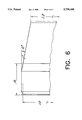
- FIG. 2 is a perspective view illustrating a core flow expansion chamber device of the present invention.
- FIG. 3 is a rear axial view of the core flow expansion chamber device of the present invention.
- FIG. 4 is an illustration of a typical chamber of the core flow expansion chamber device of the present invention.
- FIG. 5 is a diagram illustrating the gas velocity downstream of the core flow expansion chamber device according to the present invention.
- FIG. 6 is a partial view illustrating the tailpipe of the present invention.
- FIG. 7 is an illustration of a fan blade of an engine.
- FIG. 8 is an illustration of the recontouring required to a fan blade leading edge according to the present invention.
- FIG. 9 is an illustration of a typical hot and cold chute of the flow diverter device of the present invention.
- the preferred embodiment of the elements of the noise suppression system of the present invention have been sized for fit up on a Pratt & Whitney JT8D engine which is used, for example, on Douglas Corporation DC-9 and Boeing 737-100 and 737-200 aircraft. A description of the retrofit system of the preferred embodiment of the invention will therefore be described with specific reference to that engine. However, it will be recognized by persons skilled in the art that the present invention can be applied to other gas turbine bypass engines.
- FIG. 1 illustrates an exploded view of the noise suppression system of the present invention as it fits on the JT8D engine in a configuration usable on the Douglass Corporation DC-9 or Boeing 737-100 or 737-200 aircraft.
- the system is generally referenced as 1.
- Core engine 10 includes high and low pressure compressors, a combustor, and a high and low pressure turbine aligned in a series flow relationship.
- An upstream fan 11 precedes core engine 10 in the engine configuration.
- Core engine 10 includes an outer casing which defines an annular bypass duct between the outer casing and the inner casing surrounding the components of the core engine. Fan 11 is used to move a stream of air through the bypass duct of the engine.
- Noise suppression system 1 includes a device 12 for reducing noise emanating from the fan 11 known in the art as a respaced inlet guide vane or RIGV. This device removes the guide vanes controlling air entering fan 11 to a greater distance from fan 11 by means of a longer acoustically treated duct, thereby dissipating wake pressure pulses striking the fan 11 and reducing noise.
- a device 12 for reducing noise emanating from the fan 11 known in the art as a respaced inlet guide vane or RIGV. This device removes the guide vanes controlling air entering fan 11 to a greater distance from fan 11 by means of a longer acoustically treated duct, thereby dissipating wake pressure pulses striking the fan 11 and reducing noise.
- Noise suppression system 1 further includes an acoustically treated nose cowl 13 conventional for the engine, a modified fan 11, a flow diverter 14, a flow diverter support ring 16, a core flow expansion chamber device 17, a thrust reverser 18, and an acoustically treated and modified tailpipe 19.
- the addition of the flow diverter 14 and the elements of the present invention modifies the inherent gas flow pattern and the dynamics of the engine.
- the leading edges of the fan blades 37 are modified to recontour the leading edge of the fan blade and, if necessary, to decrease clearances at the mid-span shroud 38.
- the fan 11 includes a plurality of fan blades 37 which are fixed to the fan hub in a conventional manner.
- the leading edge 39 of each fan blade 37 is modified per the engine manufacturer's instructions by a special tool to create, by rechamfering, a new leading edge profile, or contour 40.
- the length of each mid-span shroud 38 shown generally in FIG. 7, must be checked and, if necessary, brought up to blueprint specifications.
- Noise suppression system 1 includes flow diverter means for directing fan air into the exhaust gas flow path downstream of the core engine and for directing exhaust gas flow into the core flow expansion chamber device 17.
- the flow diverter means comprises a flow diverter 14 which in the preferred embodiment includes twelve circumferentially spaced axially and radially elongated lobes 44 which define alternating hot and cold chutes.
- the flow diverter 14 has a plurality of alternating hot gas ducts 45 and cold gas ducts 46. Flow from the fan 11 enters into the cold gas ducts 46 which incline radially inward. The bypass gas is therefore directed toward the axis of the engine. Exhaust gas from the core of the engine flows through the hot gas ducts 45 which have a greater cross sectional area and incline outward in a radial direction thereby directing the core exhaust gas into the openings in the core flow expansion chamber device.
- a means for supporting and positioning the flow diverter 14 in the form of a flow diverter mount ring 16 are also included.
- the core flow expansion chamber device 17 reduces peak velocity of the exhaust stream and therefore reduces jet noise. Since thrust noise is a function of the peak velocity of the exhaust gas raised to the eighth power, even slight reductions in the peak overall jet velocity result in a significant lowering of the engine thrust noise.
- FIG. 5 illustrates by a comparative diagram the velocity reduction achieved by the core flow expansion chamber device system.
- the system of the present invention is designed to provide the optimum noise reduction without adversely affecting the engine efficiency.
- An example of the core flow expansion chamber device 17 is shown in FIGS. 2, 3 and 4.
- the core flow expansion chamber device 17 in the preferred embodiment is comprised of a cylindrical section 26 approximately 30 inches in length (a) and twelve circumferentially spaced exhaust chutes 27 aligned with the hot gas ducts of the flow diverter 14 through which exhaust gas from the core of the engine flows. Openings 28 in the wall of the cylindrical section 26 of the core flow expansion chamber device 17 are arranged at the points where the eflux from the hot gas ducts 45 of the flow diverter 14 would impinge on the cylindrical section 26.
- openings 28 form the entrance to the twelve circumferentially spaced exhaust chutes 27.
- the openings 28 are sized to allow the amount of gases passing through the hot gas ducts 45 of the flow diverter 14 to flow into the exhaust chutes 27.
- the openings 28 are sized at approximately 354.8 square inches (approximately 29.6 square inches per opening 28).
- chute exit 29 may appear at the point of largest chute 27 cross sectional area or the chute 27 may proceed further rearward at a constant cross sectional area prior to allowing the exhaust gases to flow into the atmosphere.
- the core flow expansion chamber device 17 of the present invention is acoustically treated by the addition of sound deadening material to the interior surfaces of the cylindrical 26 and chute 27 sections.
- This material is added to attenuate turbo-machinery noise and serves to reduce noise during the operation of the engine.
- the addition of sound deadening material to the interior surfaces of the cylindrical 26 and chute 27 sections may not be necessary for all jet engines on which the device is utilized.
- Noise suppression system 1 further includes a modified tailpipe assembly 19 which is configured to have a smaller cross sectional area in the exit plane to accommodate decreased pressure in the flow stream caused by introduction of the various components, primarily the core flow expansion chamber device 17.
- the modified tailpipe 19 for the JT8D engine has an inside inlet diameter of 34.36 inches and an inside exhaust diameter of approximately 21.25 inches.
- the tailpipe is cylindrical in shape for approximately 19.72 inches (a) and then angles inwardly at an angle of approximately 10 degrees to form a cone.
- Tailpipe assembly 19 preferably is also outfitted with acoustic inner walls so as to further suppress noise.
Abstract
A noise reduction system is provided for installation on a bypass turbine having a core engine, an outer casing and a thrust reverser. The system is comprised of an acoustically treated nose cowl conventional for the engine; a respaced inlet guide vane upstream of the core engine for reducing wake disturbances striking the engine fan; a flow diverter downstream of the core engine for turning fan air inward toward the engine center line and for turning core air outward; a structure for supporting and positioning said flow diverter relative to the engine; a core flow expansion chamber device for slowing the peak velocity of the exhaust gas prior to exhausting it to the atmosphere; and an acoustic tailpipe assembly configured to define an outlet area sized and shaped to compensate for the mass flow loss created by the core flow expansion chamber device.
Description
1. Field of the Invention
The present invention relates generally to jet aircraft turbine engines and, more specifically, to a noise reduction system for retrofit on an existing engine and airframe.
2. Description of the Related Art
In view of noise restrictions placed upon the use of aircraft, a need has existed and continues to exist for quiet aircraft engines. Due to these noise restrictions, there is a significant need for a method to modify conventional engines on aircraft that presently are in service, since aircraft with such engines often cannot continued to be used.
The prior art contains many instances of structure adapted specifically for retrofit or original fit on a jet turbine engine to suppress engine noise. Typically, the noise suppression structure consists of sound-attenuating liners applied to the nose cowl, the nose dome, and the fan duct components of the engine, a lobed mixer which mixes the core and fan flows to lower peak velocities, and in certain cases a suppressor device which draws in ambient air to be mixed with the turbine and fan flows. Examples of such installations are shown in U.S. Pat. Nos. 4,751,979, 4,723,626, 4,443,751 and 4,401,269. The installation of past prior noise suppression structures and devices in a retrofit application is generally extremely time consuming and detailed and has a significant negative impact on the aircraft. Many past systems also required significant preventative maintenance to maintain the beneficial effects of noise suppression.
In the applicants view, the past efforts to design a retrofit for aircraft engines to suppress noise levels have not been fully acceptable or successful, particularly on high thrust rated versions of these engines. Many of the past retrofit designs simply have not provided a meaningful noise reduction. Moreover, these past retrofit designs have often been prohibitively expensive and negatively impact the economic operation of the aircraft to a significant level.
Accordingly, it is an object of the present invention to provide a noise suppression system for retrofit installation on bypass type turbine engines which significantly reduce the noise from the engine perceived by ground observers, particularly during takeoff and approach operations. It is a further object of the present invention to provide a retrofit noise suppression system for a bypass turbine engine which has a minimal impact on the economic operation of the aircraft on which it is affixed.
It is a still further object of the present invention to provide a retrofit noise suppression system for a bypass turbine engine which can be installed with a minimum duration of down time and which can be easily maintained for future flight operations.
A still further object of the present invention is to provide a noise suppression system for retrofit installation on a bypass type turbine engine which is specifically adapted to maintain current back pressure levels in the exhaust gas stream, thereby significantly reducing any chance of fan stall.
Additional objects and advantages of the invention will be set forth in the description which follows, and in part will be obvious from the description, or may be learned by practice of the invention. The objects and advantages of the invention may be realized and attained by means of the elements and combinations particularly pointed out in the appended claims.
To achieve the foregoing objects, and in accordance with the purposes of the invention as embodied and broadly described herein, a noise suppression system for retrofit installation on a bypass type jet turbine engine having a core engine, an outer casing, and a thrust reverser is provided. The noise reduction system comprises flow diverter means, located downstream of the core engine, for turning fan air radially inward and core exhaust gases radially outward, means for supporting and positioning the flow diverter means relative to the engine outer casing, a core flow expansion chamber device for expanding and slowing the core flow prior to exhausting it through a defined area, a thrust reverser means to permit adequate reverse thrust with the core flow expansion chamber device in place, and an acoustic tailpipe assembly configured to define an outlet area for the engine fan flow path, the outlet area being sized and shaped to rematch pressure levels in the exhaust gas stream to compensate for the mass loss created by the core flow bleed off through the expansion chamber device.
In a preferred embodiment, the flow diverter means includes a flow diverter having an array of axially and radially elongated hot and cold chutes with fan air directed into the cold chutes and exhaust gas into the hot chutes. Hot exhaust gases from the core engine pass through the hot chutes of the flow diverter and enter the core flow expansion chambers. Fan air from the fan duct passes through the cold chutes of the flow diverter and enters the interior cylindrical section of the core flow expansion chamber device.
Preferably, a modified thrust reverser assembly is provided with the system to replace the conventional thrust reverser. The modified thrust reverser is adapted such that the core flow passed through the chamber device will be engaged by the thrust reverser during reverse operations.
In the preferred embodiment, a modified tailpipe is provided with the system to replace the conventional tailpipe. The modified tailpipe is sized to compensate for the flow diverter means being introduced into the flow stream and for the loss of mass flow through the core flow expansion chamber device, thereby reducing the mass flow passing through and exiting the tail pipe.
It is to be understood that both the foregoing general description and the following detailed description are exemplary and explanatory only and are not restrictive of the invention as claimed.
The accompanying drawings, which are incorporated in and constitute a part of the specification, illustrate a presently preferred embodiment of the invention and, together with the general description given below, serve to explain the principles of the invention.
FIG. 1 is an exploded perspective view of the elements of the noise suppression system configured to fit on, for example, a Douglas Corporation DC-9 or Boeing 737-100 or -200 aircraft in relation to the engine.
FIG. 2 is a perspective view illustrating a core flow expansion chamber device of the present invention.
FIG. 3 is a rear axial view of the core flow expansion chamber device of the present invention.
FIG. 4 is an illustration of a typical chamber of the core flow expansion chamber device of the present invention.
FIG. 5 is a diagram illustrating the gas velocity downstream of the core flow expansion chamber device according to the present invention.
FIG. 6 is a partial view illustrating the tailpipe of the present invention.
FIG. 7 is an illustration of a fan blade of an engine.
FIG. 8 is an illustration of the recontouring required to a fan blade leading edge according to the present invention.
FIG. 9 is an illustration of a typical hot and cold chute of the flow diverter device of the present invention.
Reference will now be made in detail to the presently preferred embodiment of the invention as illustrated in the accompanying drawings, wherein like reference numbers designate like or corresponding parts throughout the several drawings.
The preferred embodiment of the elements of the noise suppression system of the present invention have been sized for fit up on a Pratt & Whitney JT8D engine which is used, for example, on Douglas Corporation DC-9 and Boeing 737-100 and 737-200 aircraft. A description of the retrofit system of the preferred embodiment of the invention will therefore be described with specific reference to that engine. However, it will be recognized by persons skilled in the art that the present invention can be applied to other gas turbine bypass engines.
FIG. 1 illustrates an exploded view of the noise suppression system of the present invention as it fits on the JT8D engine in a configuration usable on the Douglass Corporation DC-9 or Boeing 737-100 or 737-200 aircraft. The system is generally referenced as 1. Core engine 10 includes high and low pressure compressors, a combustor, and a high and low pressure turbine aligned in a series flow relationship. An upstream fan 11 precedes core engine 10 in the engine configuration. Core engine 10 includes an outer casing which defines an annular bypass duct between the outer casing and the inner casing surrounding the components of the core engine. Fan 11 is used to move a stream of air through the bypass duct of the engine.
Noise suppression system 1 includes a device 12 for reducing noise emanating from the fan 11 known in the art as a respaced inlet guide vane or RIGV. This device removes the guide vanes controlling air entering fan 11 to a greater distance from fan 11 by means of a longer acoustically treated duct, thereby dissipating wake pressure pulses striking the fan 11 and reducing noise.
Noise suppression system 1 further includes an acoustically treated nose cowl 13 conventional for the engine, a modified fan 11, a flow diverter 14, a flow diverter support ring 16, a core flow expansion chamber device 17, a thrust reverser 18, and an acoustically treated and modified tailpipe 19.
As will be described below, the addition of the flow diverter 14 and the elements of the present invention modifies the inherent gas flow pattern and the dynamics of the engine. To compensate for this modification in the gas flow and engine dynamics, the leading edges of the fan blades 37 are modified to recontour the leading edge of the fan blade and, if necessary, to decrease clearances at the mid-span shroud 38. As shown generally in FIG. 1, the fan 11 includes a plurality of fan blades 37 which are fixed to the fan hub in a conventional manner. As shown generally in FIG. 8, when modifying a conventional engine, the leading edge 39 of each fan blade 37 is modified per the engine manufacturer's instructions by a special tool to create, by rechamfering, a new leading edge profile, or contour 40. In addition to the modification of the blade shape, the length of each mid-span shroud 38, shown generally in FIG. 7, must be checked and, if necessary, brought up to blueprint specifications.
Noise suppression system 1 includes flow diverter means for directing fan air into the exhaust gas flow path downstream of the core engine and for directing exhaust gas flow into the core flow expansion chamber device 17. Shown generally in FIG. 9, as embodied herein and in accordance with the invention, the flow diverter means comprises a flow diverter 14 which in the preferred embodiment includes twelve circumferentially spaced axially and radially elongated lobes 44 which define alternating hot and cold chutes.
The flow diverter 14 has a plurality of alternating hot gas ducts 45 and cold gas ducts 46. Flow from the fan 11 enters into the cold gas ducts 46 which incline radially inward. The bypass gas is therefore directed toward the axis of the engine. Exhaust gas from the core of the engine flows through the hot gas ducts 45 which have a greater cross sectional area and incline outward in a radial direction thereby directing the core exhaust gas into the openings in the core flow expansion chamber device. A means for supporting and positioning the flow diverter 14 in the form of a flow diverter mount ring 16 are also included.
As described more fully below, the core flow expansion chamber device 17 reduces peak velocity of the exhaust stream and therefore reduces jet noise. Since thrust noise is a function of the peak velocity of the exhaust gas raised to the eighth power, even slight reductions in the peak overall jet velocity result in a significant lowering of the engine thrust noise. FIG. 5 illustrates by a comparative diagram the velocity reduction achieved by the core flow expansion chamber device system.
The system of the present invention is designed to provide the optimum noise reduction without adversely affecting the engine efficiency. An example of the core flow expansion chamber device 17 is shown in FIGS. 2, 3 and 4. As embodied herein and in accordance with the invention, the core flow expansion chamber device 17 in the preferred embodiment is comprised of a cylindrical section 26 approximately 30 inches in length (a) and twelve circumferentially spaced exhaust chutes 27 aligned with the hot gas ducts of the flow diverter 14 through which exhaust gas from the core of the engine flows. Openings 28 in the wall of the cylindrical section 26 of the core flow expansion chamber device 17 are arranged at the points where the eflux from the hot gas ducts 45 of the flow diverter 14 would impinge on the cylindrical section 26. These openings 28 form the entrance to the twelve circumferentially spaced exhaust chutes 27. The openings 28 are sized to allow the amount of gases passing through the hot gas ducts 45 of the flow diverter 14 to flow into the exhaust chutes 27. In the JT8D, for example, the openings 28 are sized at approximately 354.8 square inches (approximately 29.6 square inches per opening 28).
Rearward of the opening 28 to the chute 27 the radially outer portion ("roof") 25 of the chute moves radially outward from the cylindrical section 26 ("floor") at an angle of approximately 10 degrees to the point where the distance between the I.D. of the "roof" 25 and the "floor" 26 is approximately 3 inches. Further, the side walls 24 of the chutes 27 move outward from the axial center line of the chutes 27 at an angle of approximately 10.3 degrees. This movement outward of the "roof" 25 and side walls 24 of the chute results in a constant increase in the cross sectional area of the chute 27 yielding a progressive increase in the containment volume of the chute 27. This constant increase in volume results in the gradual, constant expansion of the gas entering the chute 27, resulting in a slowing of the core flow velocity prior to the exhaust gas being expelled into the atmosphere through the chute exit 29.
It will be recognized by those schooled in the art that the chute exit 29 may appear at the point of largest chute 27 cross sectional area or the chute 27 may proceed further rearward at a constant cross sectional area prior to allowing the exhaust gases to flow into the atmosphere.
In the preferred embodiment, the core flow expansion chamber device 17 of the present invention is acoustically treated by the addition of sound deadening material to the interior surfaces of the cylindrical 26 and chute 27 sections. This material is added to attenuate turbo-machinery noise and serves to reduce noise during the operation of the engine. However, it will be recognized by those schooled in the art that the addition of sound deadening material to the interior surfaces of the cylindrical 26 and chute 27 sections may not be necessary for all jet engines on which the device is utilized.
Noise suppression system 1 further includes a modified tailpipe assembly 19 which is configured to have a smaller cross sectional area in the exit plane to accommodate decreased pressure in the flow stream caused by introduction of the various components, primarily the core flow expansion chamber device 17. With reference to FIG. 6, the modified tailpipe 19 for the JT8D engine has an inside inlet diameter of 34.36 inches and an inside exhaust diameter of approximately 21.25 inches. As shown in FIG. 6, the tailpipe is cylindrical in shape for approximately 19.72 inches (a) and then angles inwardly at an angle of approximately 10 degrees to form a cone. Tailpipe assembly 19 preferably is also outfitted with acoustic inner walls so as to further suppress noise.
Additional advantages and modifications will readily occur to those skilled in the art. Thus, the invention in its broader aspects is not limited to the specific details, representative devices and illustrative examples shown and described.
Accordingly, departures may be made from such detail without departing from the spirit or scope of the general inventive concept as defined by the appended claims and their equivalents.
Claims (8)
1. A noise reduction system for modifying a fan jet engine, the noise reduction system comprising:
(a) a flow diverter assembly having an upstream end and a downstream end, the flow diverter assembly having an annular flow diverter wall axially extending from the upstream end to the downstream end, the annular flow diverter wall being formed into a plurality of circumferentially alternating radially inward and radially outward lobes, the radially inward lobes defining cold chutes for radially inwardly diverting fan air, and the radially outward lobes defining hot chutes for radially outwardly diverting exhaust gas; and
(b) a core flow expansion chamber device at the downstream end of the flow diverter assembly, the core flow expansion chamber device being designed for expanding and slowing exhaust gas diverted radially outwardly by the flow diverter assembly.
2. A noise reduction system as claimed in claim 1, wherein the core flow expansion chamber is treated with a sound deadening material.
3. A noise reduction system as claimed in claim 1, wherein the core flow expansion chamber device has at least one exhaust chute for expanding and slowing exhaust gas diverted radially outwardly by the flow diverter assembly.
4. A noise reduction system as claimed in claim 1, wherein the core flow expansion chamber device comprises a plurality of circumferentially spaced exhaust chutes for expanding and slowing exhaust gas diverted radially outwardly by the flow diverter assembly.
5. A noise reduction system as claimed in claim 4, wherein the core flow expansion chamber device further comprises a main body portion from which the plurality of circumferentially spaced exhaust chutes extend, wherein each exhaust chute has a roof projecting from the main body portion of the core flow expansion chamber.
6. A noise reduction system as claimed in claim 5, wherein the main body portion of the core flow expansion chamber is a cylindrical portion.
7. A noise reduction system as claimed in claim 5, wherein the roof of each exhaust chute forms an angle of about 10 degrees from a longitudinal axis of the fan jet engine.
8. A noise reduction system as claimed in claim 4, wherein each of the circumferentially spaced exhaust chutes of the core flow expansion chamber device is aligned with a radially outward lobe of the flow diverter assembly for receiving radially outwardly diverted exhaust gas.
Priority Applications (1)
| Application Number | Priority Date | Filing Date | Title |
|---|---|---|---|
| US08/060,389 US5758488A (en) | 1993-05-11 | 1993-05-11 | Core flow expansion chamber device system for reduction of jet turbine engine noise |
Applications Claiming Priority (1)
| Application Number | Priority Date | Filing Date | Title |
|---|---|---|---|
| US08/060,389 US5758488A (en) | 1993-05-11 | 1993-05-11 | Core flow expansion chamber device system for reduction of jet turbine engine noise |
Publications (1)
| Publication Number | Publication Date |
|---|---|
| US5758488A true US5758488A (en) | 1998-06-02 |
Family
ID=22029162
Family Applications (1)
| Application Number | Title | Priority Date | Filing Date |
|---|---|---|---|
| US08/060,389 Expired - Fee Related US5758488A (en) | 1993-05-11 | 1993-05-11 | Core flow expansion chamber device system for reduction of jet turbine engine noise |
Country Status (1)
| Country | Link |
|---|---|
| US (1) | US5758488A (en) |
Cited By (17)
| Publication number | Priority date | Publication date | Assignee | Title |
|---|---|---|---|---|
| DE19832963C1 (en) * | 1998-07-22 | 1999-12-09 | Friedmund Nagel | Aircraft gas turbine exhaust silencer |
| US6016651A (en) * | 1997-06-24 | 2000-01-25 | Sikorsky Aircraft Corporation | Multi-stage mixer/ejector for suppressing infrared radiation |
| WO2003025378A2 (en) * | 2001-09-14 | 2003-03-27 | Mtu Aero Engines Gmbh | Device for mixing two flows of fluid, which are initially guided separate from one another, in a two-circuit reaction engine |
| US6565226B1 (en) * | 2001-11-13 | 2003-05-20 | Thomas Allen Cummings | Magazine-mounted, integral firearm lighting system |
| US20040031258A1 (en) * | 2002-03-20 | 2004-02-19 | Dimitri Papamoschou | Jet engine noise suppressor |
| US20060060417A1 (en) * | 2004-09-23 | 2006-03-23 | Williams Nicholas A | Auxiliary power unit exhaust duct with muffler incorporating an externally replaceable acoustic liner |
| US20080302083A1 (en) * | 2007-06-05 | 2008-12-11 | Sloan Mark L | Internal mixing of a portion of fan exhaust flow and full core exhaust flow in aircraft turbofan engines |
| US20100040462A1 (en) * | 2008-08-18 | 2010-02-18 | United Technologies Corporation | Separation-resistant inlet duct for mid-turbine frames |
| US20110167785A1 (en) * | 2007-06-05 | 2011-07-14 | The Boeing Company | Internal mixing of a portion of fan exhaust flow and full core exhaust flow in aircraft turbofan engines |
| US20110167786A1 (en) * | 2007-06-05 | 2011-07-14 | The Boeing Company | Internal mixing of a portion of fan exhaust flow and full core exhaust flow in aircraft turbofan engines |
| US8307943B2 (en) | 2010-07-29 | 2012-11-13 | General Electric Company | High pressure drop muffling system |
| US8430202B1 (en) | 2011-12-28 | 2013-04-30 | General Electric Company | Compact high-pressure exhaust muffling devices |
| US8511096B1 (en) | 2012-04-17 | 2013-08-20 | General Electric Company | High bleed flow muffling system |
| US8550208B1 (en) | 2012-04-23 | 2013-10-08 | General Electric Company | High pressure muffling devices |
| US9399951B2 (en) | 2012-04-17 | 2016-07-26 | General Electric Company | Modular louver system |
| US9574518B2 (en) | 2014-06-02 | 2017-02-21 | The Boeing Company | Turbofan engine with variable exhaust cooling |
| US11022071B2 (en) | 2016-12-21 | 2021-06-01 | The Boeing Company | Load distribution panel assembly, system and method |
Citations (69)
| Publication number | Priority date | Publication date | Assignee | Title |
|---|---|---|---|---|
| US2931171A (en) * | 1955-04-19 | 1960-04-05 | United Aircraft Corp | Combination noise suppressor and thrust reverser |
| US2934889A (en) * | 1956-02-14 | 1960-05-03 | United Aircraft Corp | Noise abatement means |
| US2940252A (en) * | 1956-02-07 | 1960-06-14 | Boeing Co | Gas stream thrust reaction propulsion engines with noise-suppression and thrust-reversing nozzle means |
| US2943444A (en) * | 1958-04-28 | 1960-07-05 | Ryan Aeronautical Co | Combination thrust augmenter, sound suppressor and thrust reverser for jet engines |
| US2988302A (en) * | 1959-01-14 | 1961-06-13 | Gen Sound Control Inc | Silencing means for aircraft |
| US3061038A (en) * | 1959-10-30 | 1962-10-30 | Boeing Co | Jet engine noise suppression nozzle with multiple settings |
| US3062818A (en) * | 1960-11-10 | 1962-11-06 | American Cyanamid Co | Haloalkyl-s-triazines and a new method of preparation |
| US3065818A (en) * | 1957-09-14 | 1962-11-27 | Rolls Royce | Jet noise suppressor nozzle |
| US3174282A (en) * | 1963-04-19 | 1965-03-23 | Ryan Aeronautical Co | Asymmetrical jet nozzle noise suppressor |
| US3227240A (en) * | 1964-05-04 | 1966-01-04 | Gen Electric | Air mingling sound suppressor for jet engine |
| US3289413A (en) * | 1964-08-19 | 1966-12-06 | Gen Electric | Fluid mixing apparatus for turbofan engines |
| US3455413A (en) * | 1967-08-22 | 1969-07-15 | Jack C Henley | Ultrasonic silencer for jet engines |
| US3508403A (en) * | 1968-03-28 | 1970-04-28 | Gen Electric | Turbofan engines |
| US3542152A (en) * | 1968-04-08 | 1970-11-24 | Gen Electric | Sound suppression panel |
| US3579993A (en) * | 1969-08-04 | 1971-05-25 | Rohr Corp | Sound suppression system |
| US3598318A (en) * | 1970-04-10 | 1971-08-10 | Boeing Co | Movable acoustic splitter for nozzle area control and thrust reversal |
| US3696617A (en) * | 1969-11-10 | 1972-10-10 | Rohr Corp | Turbo-fan propulsion apparatus and operating method |
| US3710890A (en) * | 1971-09-27 | 1973-01-16 | Boeing Co | Aircraft engine noise suppression |
| US3819009A (en) * | 1973-02-01 | 1974-06-25 | Gen Electric | Duct wall acoustic treatment |
| US3886737A (en) * | 1972-08-22 | 1975-06-03 | Mtu Muenchen Gmbh | Turbojet engines of multi-shaft and multi-flow construction |
| US3893640A (en) * | 1973-11-27 | 1975-07-08 | Gen Electric | Sound suppressing nacelle arrangement |
| US3954224A (en) * | 1965-07-23 | 1976-05-04 | The Boeing Company | Jet noise suppressor |
| US3982696A (en) * | 1975-07-01 | 1976-09-28 | Grumman American Aviation Corporation | Jet noise suppressor nozzle |
| US4003249A (en) * | 1975-12-29 | 1977-01-18 | The Boeing Company | Thrust correlated engine pressure ratio indicator and method for turbofan engines with mixer-type nozzles |
| US4030291A (en) * | 1976-01-02 | 1977-06-21 | General Electric Company | Thrust reverser for a gas turbofan engine |
| US4045957A (en) * | 1976-02-20 | 1977-09-06 | United Technologies Corporation | Combined guide vane and mixer for a gas turbine engine |
| US4077206A (en) * | 1976-04-16 | 1978-03-07 | The Boeing Company | Gas turbine mixer apparatus for suppressing engine core noise and engine fan noise |
| US4086761A (en) * | 1976-04-26 | 1978-05-02 | The Boeing Company | Stator bypass system for turbofan engine |
| US4117671A (en) * | 1976-12-30 | 1978-10-03 | The Boeing Company | Noise suppressing exhaust mixer assembly for ducted-fan, turbojet engine |
| US4127756A (en) * | 1977-06-27 | 1978-11-28 | Peterson Richard H | Organ stop tablet mechanism |
| US4135363A (en) * | 1976-05-13 | 1979-01-23 | United Technologies Corporation | Device to provide flow inversion in a turbofan exhaust tailpipe to achieve low jet noise |
| US4137992A (en) * | 1976-12-30 | 1979-02-06 | The Boeing Company | Turbojet engine nozzle for attenuating core and turbine noise |
| US4149375A (en) * | 1976-11-29 | 1979-04-17 | United Technologies Corporation | Lobe mixer for gas turbine engine |
| US4165609A (en) * | 1977-03-02 | 1979-08-28 | The Boeing Company | Gas turbine mixer apparatus |
| US4215536A (en) * | 1978-12-26 | 1980-08-05 | The Boeing Company | Gas turbine mixer apparatus |
| US4217756A (en) * | 1977-12-27 | 1980-08-19 | Boeing Commercial Airplane Company | Vortex mixers for reducing the noise emitted by jet engines |
| US4226085A (en) * | 1978-02-13 | 1980-10-07 | United Technologies Corporation | Unitary plug mixer and support therefor |
| US4227370A (en) * | 1977-11-04 | 1980-10-14 | Rolls-Royce Limited | By-pass gas turbine engines |
| US4235303A (en) * | 1978-11-20 | 1980-11-25 | The Boeing Company | Combination bulk absorber-honeycomb acoustic panels |
| US4240252A (en) * | 1978-01-19 | 1980-12-23 | General Electric Company | Acoustically-treated mixer for a mixed flow gas turbine engine |
| US4244441A (en) * | 1979-07-31 | 1981-01-13 | The Garrett Corporation | Broad band acoustic attenuator |
| US4289984A (en) * | 1979-10-18 | 1981-09-15 | Aroshidze Jury V | Liquid cooling of an electric machine rotor winding |
| US4291782A (en) * | 1979-10-30 | 1981-09-29 | The Boeing Company | Simplified method and apparatus for hot-shield jet noise suppression |
| US4292803A (en) * | 1979-01-19 | 1981-10-06 | Rohr Industries, Inc. | Turbo fan engine mixer |
| US4335573A (en) * | 1970-09-02 | 1982-06-22 | General Electric Company | Gas turbine engine mixer |
| US4384634A (en) * | 1979-12-18 | 1983-05-24 | United Technologies Corporation | Sound absorbing structure |
| US4401269A (en) * | 1980-09-26 | 1983-08-30 | United Technologies Corporation | Lobe mixer for gas turbine engine |
| US4422524A (en) * | 1982-03-22 | 1983-12-27 | Lockheed Corporation | Variable shape, fluid flow nozzle for sound suppression |
| GB2123486A (en) * | 1982-07-12 | 1984-02-01 | Gen Electric | Turbofan mixed flow exhaust system |
| US4433751A (en) * | 1981-12-09 | 1984-02-28 | Pratt & Whitney Aircraft Of Canada Limited | Sound suppressor liner |
| US4449607A (en) * | 1981-01-29 | 1984-05-22 | S.N.E.C.M.A. | Soundproofing for a gas pipe, in particular for the fan jet of a turbojet, and equipment for its fabrication |
| US4452335A (en) * | 1982-05-03 | 1984-06-05 | United Technologies Corporation | Sound absorbing structure for a gas turbine engine |
| US4501393A (en) * | 1982-03-17 | 1985-02-26 | The Boeing Company | Internally ventilated noise suppressor with large plug nozzle |
| US4516660A (en) * | 1980-09-22 | 1985-05-14 | Greenlaw Alfred L | Ejector and method for controlling jet engine noise |
| US4696159A (en) * | 1986-08-04 | 1987-09-29 | United Technologies Corporation | Gas turbine outlet arrangement |
| US4723626A (en) * | 1985-08-26 | 1988-02-09 | Aeronautic Development Corporation, Ltd. | Quiet nacelle system and hush kit |
| US4751979A (en) * | 1985-05-16 | 1988-06-21 | Airborne Express, Inc. | Engine noise suppression kit for the nacelles of a jet aircraft |
| US4754924A (en) * | 1987-04-03 | 1988-07-05 | Shannon Aubrey J | Variable geometry nozzle |
| US4759513A (en) * | 1986-09-26 | 1988-07-26 | Quiet Nacelle Corporation | Noise reduction nacelle |
| US4836469A (en) * | 1987-05-29 | 1989-06-06 | Valsan Partners Limited Partnership | System for reducing aircraft noise and hush kit |
| US4909346A (en) * | 1989-06-27 | 1990-03-20 | Nordam | Jet engine noise suppression system |
| US4979587A (en) * | 1989-08-01 | 1990-12-25 | The Boeing Company | Jet engine noise suppressor |
| US5014815A (en) * | 1989-06-26 | 1991-05-14 | Grumman Aerospace Corporation | Acoustic liner |
| US5058703A (en) * | 1987-11-23 | 1991-10-22 | United Technologies Corporation | Automotive exhaust noise attenuator |
| US5127602A (en) * | 1989-11-21 | 1992-07-07 | Federal Express Corporation | Noise reduction kit for jet turbine engines |
| US5133194A (en) * | 1991-02-04 | 1992-07-28 | United Technologies Corporation | Air cycle machine and fan inlet/diffuser therefor |
| US5154052A (en) * | 1990-05-07 | 1992-10-13 | General Electric Company | Exhaust assembly for a high speed civil transport aircraft engine |
| US5157916A (en) * | 1990-11-02 | 1992-10-27 | United Technologies Corporation | Apparatus and method for suppressing sound in a gas turbine engine powerplant |
| US5167118A (en) * | 1989-11-06 | 1992-12-01 | Nordam | Jet engine fixed plug noise suppressor |
-
1993
- 1993-05-11 US US08/060,389 patent/US5758488A/en not_active Expired - Fee Related
Patent Citations (70)
| Publication number | Priority date | Publication date | Assignee | Title |
|---|---|---|---|---|
| US2931171A (en) * | 1955-04-19 | 1960-04-05 | United Aircraft Corp | Combination noise suppressor and thrust reverser |
| US2940252A (en) * | 1956-02-07 | 1960-06-14 | Boeing Co | Gas stream thrust reaction propulsion engines with noise-suppression and thrust-reversing nozzle means |
| US2934889A (en) * | 1956-02-14 | 1960-05-03 | United Aircraft Corp | Noise abatement means |
| US3065818A (en) * | 1957-09-14 | 1962-11-27 | Rolls Royce | Jet noise suppressor nozzle |
| US2943444A (en) * | 1958-04-28 | 1960-07-05 | Ryan Aeronautical Co | Combination thrust augmenter, sound suppressor and thrust reverser for jet engines |
| US2988302A (en) * | 1959-01-14 | 1961-06-13 | Gen Sound Control Inc | Silencing means for aircraft |
| US3061038A (en) * | 1959-10-30 | 1962-10-30 | Boeing Co | Jet engine noise suppression nozzle with multiple settings |
| US3062818A (en) * | 1960-11-10 | 1962-11-06 | American Cyanamid Co | Haloalkyl-s-triazines and a new method of preparation |
| US3174282A (en) * | 1963-04-19 | 1965-03-23 | Ryan Aeronautical Co | Asymmetrical jet nozzle noise suppressor |
| US3227240A (en) * | 1964-05-04 | 1966-01-04 | Gen Electric | Air mingling sound suppressor for jet engine |
| US3289413A (en) * | 1964-08-19 | 1966-12-06 | Gen Electric | Fluid mixing apparatus for turbofan engines |
| US3954224A (en) * | 1965-07-23 | 1976-05-04 | The Boeing Company | Jet noise suppressor |
| US3455413A (en) * | 1967-08-22 | 1969-07-15 | Jack C Henley | Ultrasonic silencer for jet engines |
| US3508403A (en) * | 1968-03-28 | 1970-04-28 | Gen Electric | Turbofan engines |
| US3542152A (en) * | 1968-04-08 | 1970-11-24 | Gen Electric | Sound suppression panel |
| US3579993A (en) * | 1969-08-04 | 1971-05-25 | Rohr Corp | Sound suppression system |
| US3696617A (en) * | 1969-11-10 | 1972-10-10 | Rohr Corp | Turbo-fan propulsion apparatus and operating method |
| US3598318A (en) * | 1970-04-10 | 1971-08-10 | Boeing Co | Movable acoustic splitter for nozzle area control and thrust reversal |
| US4335573A (en) * | 1970-09-02 | 1982-06-22 | General Electric Company | Gas turbine engine mixer |
| US3710890A (en) * | 1971-09-27 | 1973-01-16 | Boeing Co | Aircraft engine noise suppression |
| US3886737A (en) * | 1972-08-22 | 1975-06-03 | Mtu Muenchen Gmbh | Turbojet engines of multi-shaft and multi-flow construction |
| US3819009A (en) * | 1973-02-01 | 1974-06-25 | Gen Electric | Duct wall acoustic treatment |
| US3893640A (en) * | 1973-11-27 | 1975-07-08 | Gen Electric | Sound suppressing nacelle arrangement |
| US3982696A (en) * | 1975-07-01 | 1976-09-28 | Grumman American Aviation Corporation | Jet noise suppressor nozzle |
| US4003249A (en) * | 1975-12-29 | 1977-01-18 | The Boeing Company | Thrust correlated engine pressure ratio indicator and method for turbofan engines with mixer-type nozzles |
| US4030291A (en) * | 1976-01-02 | 1977-06-21 | General Electric Company | Thrust reverser for a gas turbofan engine |
| US4045957A (en) * | 1976-02-20 | 1977-09-06 | United Technologies Corporation | Combined guide vane and mixer for a gas turbine engine |
| US4077206A (en) * | 1976-04-16 | 1978-03-07 | The Boeing Company | Gas turbine mixer apparatus for suppressing engine core noise and engine fan noise |
| US4086761A (en) * | 1976-04-26 | 1978-05-02 | The Boeing Company | Stator bypass system for turbofan engine |
| US4135363A (en) * | 1976-05-13 | 1979-01-23 | United Technologies Corporation | Device to provide flow inversion in a turbofan exhaust tailpipe to achieve low jet noise |
| US4149375A (en) * | 1976-11-29 | 1979-04-17 | United Technologies Corporation | Lobe mixer for gas turbine engine |
| US4117671A (en) * | 1976-12-30 | 1978-10-03 | The Boeing Company | Noise suppressing exhaust mixer assembly for ducted-fan, turbojet engine |
| US4137992A (en) * | 1976-12-30 | 1979-02-06 | The Boeing Company | Turbojet engine nozzle for attenuating core and turbine noise |
| US4165609A (en) * | 1977-03-02 | 1979-08-28 | The Boeing Company | Gas turbine mixer apparatus |
| US4127756A (en) * | 1977-06-27 | 1978-11-28 | Peterson Richard H | Organ stop tablet mechanism |
| US4227370A (en) * | 1977-11-04 | 1980-10-14 | Rolls-Royce Limited | By-pass gas turbine engines |
| US4217756A (en) * | 1977-12-27 | 1980-08-19 | Boeing Commercial Airplane Company | Vortex mixers for reducing the noise emitted by jet engines |
| US4240252A (en) * | 1978-01-19 | 1980-12-23 | General Electric Company | Acoustically-treated mixer for a mixed flow gas turbine engine |
| US4226085A (en) * | 1978-02-13 | 1980-10-07 | United Technologies Corporation | Unitary plug mixer and support therefor |
| US4235303A (en) * | 1978-11-20 | 1980-11-25 | The Boeing Company | Combination bulk absorber-honeycomb acoustic panels |
| US4215536A (en) * | 1978-12-26 | 1980-08-05 | The Boeing Company | Gas turbine mixer apparatus |
| US4292803A (en) * | 1979-01-19 | 1981-10-06 | Rohr Industries, Inc. | Turbo fan engine mixer |
| US4244441A (en) * | 1979-07-31 | 1981-01-13 | The Garrett Corporation | Broad band acoustic attenuator |
| US4289984A (en) * | 1979-10-18 | 1981-09-15 | Aroshidze Jury V | Liquid cooling of an electric machine rotor winding |
| US4291782A (en) * | 1979-10-30 | 1981-09-29 | The Boeing Company | Simplified method and apparatus for hot-shield jet noise suppression |
| US4384634A (en) * | 1979-12-18 | 1983-05-24 | United Technologies Corporation | Sound absorbing structure |
| US4516660A (en) * | 1980-09-22 | 1985-05-14 | Greenlaw Alfred L | Ejector and method for controlling jet engine noise |
| US4401269A (en) * | 1980-09-26 | 1983-08-30 | United Technologies Corporation | Lobe mixer for gas turbine engine |
| US4449607A (en) * | 1981-01-29 | 1984-05-22 | S.N.E.C.M.A. | Soundproofing for a gas pipe, in particular for the fan jet of a turbojet, and equipment for its fabrication |
| US4433751A (en) * | 1981-12-09 | 1984-02-28 | Pratt & Whitney Aircraft Of Canada Limited | Sound suppressor liner |
| US4501393A (en) * | 1982-03-17 | 1985-02-26 | The Boeing Company | Internally ventilated noise suppressor with large plug nozzle |
| US4422524A (en) * | 1982-03-22 | 1983-12-27 | Lockheed Corporation | Variable shape, fluid flow nozzle for sound suppression |
| US4452335A (en) * | 1982-05-03 | 1984-06-05 | United Technologies Corporation | Sound absorbing structure for a gas turbine engine |
| GB2123486A (en) * | 1982-07-12 | 1984-02-01 | Gen Electric | Turbofan mixed flow exhaust system |
| US4751979A (en) * | 1985-05-16 | 1988-06-21 | Airborne Express, Inc. | Engine noise suppression kit for the nacelles of a jet aircraft |
| US4723626A (en) * | 1985-08-26 | 1988-02-09 | Aeronautic Development Corporation, Ltd. | Quiet nacelle system and hush kit |
| US4696159A (en) * | 1986-08-04 | 1987-09-29 | United Technologies Corporation | Gas turbine outlet arrangement |
| US4759513A (en) * | 1986-09-26 | 1988-07-26 | Quiet Nacelle Corporation | Noise reduction nacelle |
| US4754924A (en) * | 1987-04-03 | 1988-07-05 | Shannon Aubrey J | Variable geometry nozzle |
| US4836469A (en) * | 1987-05-29 | 1989-06-06 | Valsan Partners Limited Partnership | System for reducing aircraft noise and hush kit |
| US5058703A (en) * | 1987-11-23 | 1991-10-22 | United Technologies Corporation | Automotive exhaust noise attenuator |
| US5014815A (en) * | 1989-06-26 | 1991-05-14 | Grumman Aerospace Corporation | Acoustic liner |
| US4909346A (en) * | 1989-06-27 | 1990-03-20 | Nordam | Jet engine noise suppression system |
| US4979587A (en) * | 1989-08-01 | 1990-12-25 | The Boeing Company | Jet engine noise suppressor |
| US5167118A (en) * | 1989-11-06 | 1992-12-01 | Nordam | Jet engine fixed plug noise suppressor |
| US5127602A (en) * | 1989-11-21 | 1992-07-07 | Federal Express Corporation | Noise reduction kit for jet turbine engines |
| US5127602B1 (en) * | 1989-11-21 | 1995-05-02 | Federal Express Corp | Noise reduction kit for jet turbine engines. |
| US5154052A (en) * | 1990-05-07 | 1992-10-13 | General Electric Company | Exhaust assembly for a high speed civil transport aircraft engine |
| US5157916A (en) * | 1990-11-02 | 1992-10-27 | United Technologies Corporation | Apparatus and method for suppressing sound in a gas turbine engine powerplant |
| US5133194A (en) * | 1991-02-04 | 1992-07-28 | United Technologies Corporation | Air cycle machine and fan inlet/diffuser therefor |
Non-Patent Citations (17)
| Title |
|---|
| A.B. Packman and D.C. Eiler, Internal Mixer Investigation for JT8D Engine Jet Noise Reduction, Rpt. No. FAA RD 77 132 (1977) (prepared for Dept. of Transportation, Federal Aviation Administration). * |
| A.B. Packman and D.C. Eiler, Internal Mixer Investigation for JT8D Engine Jet Noise Reduction, Rpt. No. FAA-RD-77-132 (1977) (prepared for Dept. of Transportation, Federal Aviation Administration). |
| Airline Observer, Aviation Week, Oct. 3, 1988, at 13 (announcing Quiet Nacelle Corp. JT8D hush kit). * |
| Bernhard H. Goethert, Noise Attenuation and Associated Thrust Increase of Turbojet Engines Through Hyper Mixing Ejector Shrouds, Fifth International Symposium on Air Breathing Engines: Symposium Papers 17 1 (1981). * |
| Bernhard H. Goethert, Noise Attenuation and Associated Thrust Increase of Turbojet Engines Through Hyper-Mixing Ejector Shrouds, Fifth International Symposium on Air Breathing Engines: Symposium Papers 17-1 (1981). |
| David Woolley, Hush kit Manufacturers Scramble to Equip Older Jets, Interavia, Jun. 1985, at 634. * |
| David Woolley, Hush-kit Manufacturers Scramble to Equip Older Jets, Interavia, Jun. 1985, at 634. |
| F.G. Strout and A. Atencio Jr., Flight Effects on Noise Generated by a JT8D Engine with Inverted Primary/Fan Flow, Journal of Aircraft, Jan. 1980, at 13. * |
| F.H. Pond and R.A. Heinz, JT8D Engine Internal Exhaust Mixer Technology Program: Final Report, Rpt. No. FAA 80 69 (1980) (prepared for U.S. Dept. of Transportation, Federal Aviation Administration). * |
| F.H. Pond and R.A. Heinz, JT8D Engine Internal Exhaust Mixer Technology Program: Final Report, Rpt. No. FAA-80-69 (1980) (prepared for U.S. Dept. of Transportation, Federal Aviation Administration). |
| General Electric Co., High Velocity Jet Noise Source Location and Reduction: Task 2 Theoretical Developments and Basic Experiments, Rpt. No. FAA RD 76 79 (1978) (prepared for Dept. of Transportation, Federal Aviation Administration). * |
| General Electric Co., High Velocity Jet Noise Source Location and Reduction: Task 2--Theoretical Developments and Basic Experiments, Rpt. No. FAA-RD-76-79 (1978) (prepared for Dept. of Transportation, Federal Aviation Administration). |
| General Electric Co., High Velocity Jet Noise Source Location and Reduction: Task 6 Noise Abatement Nozzle Design Guide, Rpt. No. FAA RD 76 79 (1979) (prepared for Dept. of Transportation, Federal Aviation Administration). * |
| General Electric Co., High Velocity Jet Noise Source Location and Reduction: Task 6--Noise Abatement Nozzle Design Guide, Rpt. No. FAA-RD-76-79 (1979) (prepared for Dept. of Transportation, Federal Aviation Administration). |
| News Briefs, Aviation Week, May 2, 1988, at 34 (announcing Pratt & Whitney hush kit using mixer). * |
| Nordman JT 8 Hushkit, Flight International, Aug. 1990, at 6 (photograph of a new product). * |
| Nordman JT-8 Hushkit, Flight International, Aug. 1990, at 6 (photograph of a new product). |
Cited By (28)
| Publication number | Priority date | Publication date | Assignee | Title |
|---|---|---|---|---|
| US6016651A (en) * | 1997-06-24 | 2000-01-25 | Sikorsky Aircraft Corporation | Multi-stage mixer/ejector for suppressing infrared radiation |
| DE19832963C1 (en) * | 1998-07-22 | 1999-12-09 | Friedmund Nagel | Aircraft gas turbine exhaust silencer |
| WO2003025378A2 (en) * | 2001-09-14 | 2003-03-27 | Mtu Aero Engines Gmbh | Device for mixing two flows of fluid, which are initially guided separate from one another, in a two-circuit reaction engine |
| WO2003025378A3 (en) * | 2001-09-14 | 2003-05-30 | Mtu Aero Engines Gmbh | Device for mixing two flows of fluid, which are initially guided separate from one another, in a two-circuit reaction engine |
| US20050022502A1 (en) * | 2001-09-14 | 2005-02-03 | Karl Katheder | Device for mixing two flows of fluid which are initially guided separate from one another in a two-circuit reaction engine |
| US7299635B2 (en) | 2001-09-14 | 2007-11-27 | Mtu Aero Engines Gmbh | Device for mixing two flows of fluid which are initially guided separate from one another in a bypass jet engine |
| US6565226B1 (en) * | 2001-11-13 | 2003-05-20 | Thomas Allen Cummings | Magazine-mounted, integral firearm lighting system |
| US20040031258A1 (en) * | 2002-03-20 | 2004-02-19 | Dimitri Papamoschou | Jet engine noise suppressor |
| US7293401B2 (en) | 2002-03-20 | 2007-11-13 | The Regents Of The University Of California | Jet engine noise suppressor |
| US20060060417A1 (en) * | 2004-09-23 | 2006-03-23 | Williams Nicholas A | Auxiliary power unit exhaust duct with muffler incorporating an externally replaceable acoustic liner |
| US7350619B2 (en) * | 2004-09-23 | 2008-04-01 | Honeywell International, Inc. | Auxiliary power unit exhaust duct with muffler incorporating an externally replaceable acoustic liner |
| US20110167785A1 (en) * | 2007-06-05 | 2011-07-14 | The Boeing Company | Internal mixing of a portion of fan exhaust flow and full core exhaust flow in aircraft turbofan engines |
| US10094334B2 (en) | 2007-06-05 | 2018-10-09 | The Boeing Company | Internal mixing of a portion of fan exhaust flow and full core exhaust flow in aircraft turbofan engines |
| US7762057B2 (en) | 2007-06-05 | 2010-07-27 | The Boeing Company | Internal mixing of a portion of fan exhaust flow and full core exhaust flow in aircraft turbofan engines |
| US20080302083A1 (en) * | 2007-06-05 | 2008-12-11 | Sloan Mark L | Internal mixing of a portion of fan exhaust flow and full core exhaust flow in aircraft turbofan engines |
| US20110167786A1 (en) * | 2007-06-05 | 2011-07-14 | The Boeing Company | Internal mixing of a portion of fan exhaust flow and full core exhaust flow in aircraft turbofan engines |
| US8341935B2 (en) | 2007-06-05 | 2013-01-01 | The Boeing Company | Internal mixing of a portion of fan exhaust flow and full core exhaust flow in aircraft turbofan engines |
| US10954890B2 (en) | 2007-06-05 | 2021-03-23 | The Boeing Company | Internal mixing of a portion of fan exhaust flow and full core exhaust flow in aircraft turbofan engines |
| US8726665B2 (en) | 2007-06-05 | 2014-05-20 | The Boeing Company | Internal mixing of a portion of fan exhaust flow and full core exhaust flow in aircraft turbofan engines |
| US8061980B2 (en) | 2008-08-18 | 2011-11-22 | United Technologies Corporation | Separation-resistant inlet duct for mid-turbine frames |
| US20100040462A1 (en) * | 2008-08-18 | 2010-02-18 | United Technologies Corporation | Separation-resistant inlet duct for mid-turbine frames |
| US8307943B2 (en) | 2010-07-29 | 2012-11-13 | General Electric Company | High pressure drop muffling system |
| US8430202B1 (en) | 2011-12-28 | 2013-04-30 | General Electric Company | Compact high-pressure exhaust muffling devices |
| US8511096B1 (en) | 2012-04-17 | 2013-08-20 | General Electric Company | High bleed flow muffling system |
| US9399951B2 (en) | 2012-04-17 | 2016-07-26 | General Electric Company | Modular louver system |
| US8550208B1 (en) | 2012-04-23 | 2013-10-08 | General Electric Company | High pressure muffling devices |
| US9574518B2 (en) | 2014-06-02 | 2017-02-21 | The Boeing Company | Turbofan engine with variable exhaust cooling |
| US11022071B2 (en) | 2016-12-21 | 2021-06-01 | The Boeing Company | Load distribution panel assembly, system and method |
Similar Documents
| Publication | Publication Date | Title |
|---|---|---|
| US5758488A (en) | Core flow expansion chamber device system for reduction of jet turbine engine noise | |
| US5127602A (en) | Noise reduction kit for jet turbine engines | |
| US5884472A (en) | Alternating lobed mixer/ejector concept suppressor | |
| US4692091A (en) | Low noise fan | |
| US3806067A (en) | Area ruled nacelle | |
| EP0984152B1 (en) | Tabbed nozzle for jet noise suppression | |
| EP0635632B1 (en) | Noise suppression system | |
| US3611724A (en) | Choked inlet noise suppression device for a turbofan engine | |
| US4979587A (en) | Jet engine noise suppressor | |
| US5638675A (en) | Double lobed mixer with major and minor lobes | |
| US5761900A (en) | Two-stage mixer ejector suppressor | |
| JP5264184B2 (en) | Bleed structure for a bleed passage in a gas turbine engine | |
| EP1340901B1 (en) | Noise attenuating segmented exhaust nozzle | |
| EP1397586B1 (en) | Exhaust flow guide for jet noise reduction | |
| US4782912A (en) | Engine air cleaner - noise reducer | |
| US3843277A (en) | Sound attenuating inlet duct | |
| EP1343962B1 (en) | Gas turbine engine | |
| US5947412A (en) | Jet engine noise suppressor assembly | |
| US4537277A (en) | Silencer for high velocity gas flow | |
| US5592813A (en) | Hush kit for jet engine | |
| GB2058929A (en) | Foreign particle separator system | |
| US4240252A (en) | Acoustically-treated mixer for a mixed flow gas turbine engine | |
| US3648800A (en) | Coanda expansion exhaust nozzle suppressor | |
| EP3633174B1 (en) | Acoustic torque box | |
| US4474259A (en) | Internally ventilated noise suppressor for jet engine |
Legal Events
| Date | Code | Title | Description |
|---|---|---|---|
| AS | Assignment |
Owner name: THOMSON, RODERICK, NEW YORK Free format text: ASSIGNMENT OF ASSIGNORS INTEREST;ASSIGNOR:BATEY, J. GARY;REEL/FRAME:006705/0453 Effective date: 19930827 |
|
| REMI | Maintenance fee reminder mailed | ||
| LAPS | Lapse for failure to pay maintenance fees | ||
| STCH | Information on status: patent discontinuation |
Free format text: PATENT EXPIRED DUE TO NONPAYMENT OF MAINTENANCE FEES UNDER 37 CFR 1.362 |
|
| FP | Lapsed due to failure to pay maintenance fee |
Effective date: 20020602 |