US5367970A - Controllable camber fin - Google Patents
Controllable camber fin Download PDFInfo
- Publication number
- US5367970A US5367970A US08/127,181 US12718193A US5367970A US 5367970 A US5367970 A US 5367970A US 12718193 A US12718193 A US 12718193A US 5367970 A US5367970 A US 5367970A
- Authority
- US
- United States
- Prior art keywords
- fin
- control wires
- foil
- structural element
- camber
- Prior art date
- Legal status (The legal status is an assumption and is not a legal conclusion. Google has not performed a legal analysis and makes no representation as to the accuracy of the status listed.)
- Expired - Fee Related
Links
Images

Classifications
-
- B—PERFORMING OPERATIONS; TRANSPORTING
- B64—AIRCRAFT; AVIATION; COSMONAUTICS
- B64C—AEROPLANES; HELICOPTERS
- B64C3/00—Wings
- B64C3/38—Adjustment of complete wings or parts thereof
- B64C3/44—Varying camber
- B64C3/48—Varying camber by relatively-movable parts of wing structures
-
- B—PERFORMING OPERATIONS; TRANSPORTING
- B63—SHIPS OR OTHER WATERBORNE VESSELS; RELATED EQUIPMENT
- B63B—SHIPS OR OTHER WATERBORNE VESSELS; EQUIPMENT FOR SHIPPING
- B63B39/00—Equipment to decrease pitch, roll, or like unwanted vessel movements; Apparatus for indicating vessel attitude
- B63B39/06—Equipment to decrease pitch, roll, or like unwanted vessel movements; Apparatus for indicating vessel attitude to decrease vessel movements by using foils acting on ambient water
-
- B—PERFORMING OPERATIONS; TRANSPORTING
- B63—SHIPS OR OTHER WATERBORNE VESSELS; RELATED EQUIPMENT
- B63H—MARINE PROPULSION OR STEERING
- B63H25/00—Steering; Slowing-down otherwise than by use of propulsive elements; Dynamic anchoring, i.e. positioning vessels by means of main or auxiliary propulsive elements
- B63H25/06—Steering by rudders
- B63H25/38—Rudders
- B63H25/381—Rudders with flaps
-
- Y—GENERAL TAGGING OF NEW TECHNOLOGICAL DEVELOPMENTS; GENERAL TAGGING OF CROSS-SECTIONAL TECHNOLOGIES SPANNING OVER SEVERAL SECTIONS OF THE IPC; TECHNICAL SUBJECTS COVERED BY FORMER USPC CROSS-REFERENCE ART COLLECTIONS [XRACs] AND DIGESTS
- Y02—TECHNOLOGIES OR APPLICATIONS FOR MITIGATION OR ADAPTATION AGAINST CLIMATE CHANGE
- Y02T—CLIMATE CHANGE MITIGATION TECHNOLOGIES RELATED TO TRANSPORTATION
- Y02T50/00—Aeronautics or air transport
- Y02T50/10—Drag reduction
Definitions
- the present invention relates to variable camber fins for use in a moving fluid to influence that fluids flow over the fin.
- Variable camber airfoil shapes have been utilized since the beginning of aviation to achieve control of an aircraft in flight, and also to achieve an increased amount of lift on the airfoil particularly at low speeds.
- Such prior art airfoil shapes are shown in the following patents; Gallaudet U.S. Pat. No. 1,219,285; Stupar U.S. Pat. No. 1,220,374; and Antoni et al U.S. Pat. No. 1,317,413. All of these early airfoil designs provide external wires that are tensioned to achieve changes in the camber of a wing. However, all these control wires are provided externally to the airfoil itself.
- the present invention relates to a variable camber fin particularly well suited for use in an underwater environment where the control wires cannot be provided externally of the foil cross section. Such a requirement is particularly important in the environment of naval operations so as to eliminate the "noise" otherwise created by providing control wires outside a fin on a naval vessel.
- Cincotta et al U.S. Pat. No. 5,114,104, utilizes "shape memory alloy” wires adapted to be contracted an elongated selectively as a result of the application or removal of heat.
- the wires are provided in the skin surface of the fin itself, which skin is fabricated from an elastomeric material and therefore is readily altered in configuration so as to achieve two distinct foil shapes made possible by these "shape memory alloy” wires.
- the Cincotta patent is relevant to the present disclosure only insofar as the outer skin of the foil fin is fabricated from an elastomeric material.
- Another object is to provide an improved variable camber fin for use in a moving fluid so as to enhance the control characteristics of underwater vehicles generally.
- This invention also has particular applicability to the keel of a sailboat, and will permit control of the direction taken by a sailboat equipped with a keel construction in accordance with the present invention solely as a result of altering the foil shape of the keel itself.
- a flexible controllable camber foil of the present invention permits development of systems for steering a sailboat solely by actuation of leading and trailing edges of the sailboat keel.
- the system can also be used to camber the keel to resist sideslip or increase the righting moment of keel.
- variable camber fin for use in a moving fluid to influence that fluids flow over the fin surface or skin.
- the invention includes providing a closed foil cross section designed to minimize drag forces on the fin at a particular design equilibrium condition, such as when the fin moves through the fluid at "zero" angle of attack.
- the fin is preferably symmetrical about the chordwise direction, and has in such symmetrical shape "zero" camber.
- Camber is defined as that line created by constructing a line connecting the leading and trailing edges of the foil so as to provide an equidistant relationship between one and the opposite surface of the foil outer surface or skin.
- the foil shaped fin of the invention has a chordwise cross section that includes at least one fixed foil portion adapted to be secured to other structure, such as the hull of a vessel.
- the foil fin cross section also includes at least another foil portion that is connected to said fixed foil portion such that these portions cooperate to define a chordwise segment of the closed foil cross section.
- the latter foil portion has a structure similar to that of a cantilevered beam, the beam having a neutral axis generally oriented in the chordwise direction, and this cantilevered beam foil portion is connected at its root end to the one fixed foil portion mentioned previously.
- the cantilevered beam foil portion has a free end that is spaced in a chordwise direction from the root end, and internally mounted control wires are provided at least some of which are on one side of the neutral axis of the cantilevered beam while others are provided on the opposite side of the neutral axis.
- These control wires have ends secured to the cantilevered beam and at its free end, and means is provided for differentially stressing or tensioning some of these control wires relative the others in order to strain the cantilevered beam foil portion and thereby change the camber of the fin.
- the external surface of the fin is defined by an elastomeric skin so as to permit this flexing of the cantilevered beam foil portion.
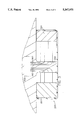
- FIG. 1 shows in a chordwise sectional view the construction of a variable camber fin constructed in accordance with the present invention
- FIG. 2 shows the fin of FIG. 1 in alternative positions made possible as a result of the flexible fin portion that is cantilevered from the fixed fin portion, illustrated in this view as the leading edge portion of the fin;
- FIG. 3 is a schematic view illustrating a conventional sailboat hull fitted with a keel constructed in accordance with the present invention.
- FIG. 4 is a cross section of the keel shown in FIG. 3.
- variable camber fin constructed in accordance with the present invention, and having a fixed leading edge portion 2 that is adapted to be secured to other structure (not shown) such as the hull of a naval vessel or missile, as for example an underwater submersible vehicle or the like.
- the variable camber fin of FIG. 1 would, when installed on such a vehicle, extend outwardly relative the longitudinal axis of such a vehicle so as to permit the variable camber fin to be manipulated for purposes of controlling the direction taken by the vehicle as it moves through the fluid or water environment.
- variable camber fin of FIG. 1 also includes at least another foil portion that is connected to the fixed foil portion such that both portions cooperate to define at least a chordwise segment of the foil cross section.
- this "another" foil portion comprises that portion between the leading edge 2 and the trailing edge portion 4 of the fin cross section.
- the trailing edge portion 4 of the fin of FIG. 1 is movable only in response to movement of the intermediate "another" portion.
- the structure of said "another" foil portion is that of a cantilevered beam having a neutral axis oriented generally in the chordwise direction. See for example FIG. 2 wherein the neutral axis of the variable camber fin in its undeformed or normal configuration is represented by a line 20. Note also that this line 20 also represents the camber of the undeformed fin as well as defining said neutral axis.
- variable camber fin of FIGS. 1 and 2 is adapted to be deflected by means to be described so as to assume various positions between the limit positions illustrated in FIG. 2. More particularly FIG. 2 shows in full lines the downward limit position of the variable camber fin with the neutral axis or camber line illustrated at 20a. This view of FIG. 2 also illustrates the variable camber fin in an upward limit position wherein the camber or neutral axis is illustrated generally at 20b. Means to be described achieves various degrees of deflection between these two limit positions of FIG. 2 solely as a result of varying the tension as between the control wires provided in the cantilevered beam foil portion of the fin, as indicated generally at 22 in FIG. 1.
- root end is connected to the leading edge portion 2 so as to permit deflection of the cantilevered beam foil portion 22 in the manner of a cantilevered beam.
- the free end of the beam 22 is indicated by 22b and it is in turn connected to a trailing edge portion 4.
- a resilient backbone member 12 is provided at the neutral axis of the cantilevered beam foil portion 22 as suggested generally at 12 in FIG. 1, and this resilient backbone 12 preferably takes the form of a leaf spring that is secured to the fixed foil portion.
- This element 12 provides a degree of rigidity to the cantilevered portion 22 so that the portion 22 can be deflected or "strained” in bending, but which will act to prevent deflection of this cantilevered beam foil portion in a "shear" mode.
- the outer skin of the fin is defined by an elastomeric material as suggested generally at 6 that provides a skin for the foil, which skin is of variable length so as to provide the desired deflection of the cantilevered foil portion in the manner suggested in FIG. 2.
- the skin is supported by stiffeners 14 spaced chordwise along the fin between its leading and trailing edges.
- control wires 10 are provided between the neutral axis defined by the backbone 12 of the fin and the aforementioned elastomeric skin 6. These wires are loosely received in openings defined by the stiffeners 14. These control wires have ends secured to said free ends of said cantilevered beam foil portion, and more particularly to the trailing edge portion 4.
- Means is provided for differentially stressing, that is by tensioning, the control wires provided on one side of the neutral axis relative to the control wires provided on the opposite side of the neutral axis of the cantilevered beam foil portion. This tensioning may be accomplished by conventional means (not shown) and is preferably tied into the control system for the vehicle itself so as to permit control of the direction taken by the vehicle in the fluid.
- control system may comprise, for example, a fire control system, or may be manually manipulated by a conventional yoke or control wheel or the like, or may be part of the response generated by an autopilot system.
- a conventional sailboat hull has an attached keel 200 that is designed to have variable camber as described previously with reference to the fin of FIGS. 1 and 2. More particularly, the keel 200 is fitted with a plurality of control wires as indicated generally at 260, 260 provided on opposite sides of a vertical center line or neutral axis that is perpendicular to the horizontally extending longitudinal axis of the hull of the vessel.
- the central portion of the keel 200 is fixed to the underside of the hull, and to this central portion 202 are secured in cantilever fashion two, or first and second, cantilevered beam foil portions. Their root ends are connected to said first mentioned fixed foil portion 202 by wires and by a spine or backbone element.
- cantilevered beam foil portions are arranged opposite one another and cooperate with the fixed central portion 202 to define a generally symmetrical keel, at least when the keel is in its non-deflected or undeformed position as referred to previously with respect to the fin of FIG. 2.
- the keel can be configured to have a linear chordwise camber.
- Both the first and the second cantilevered beam foil portions have internally mounted control wires some of which are provided on one side of their respective neutral axes of these cantilevered beam foil portions.
- the first mentioned cantilevered beam foil portion 220 comprises the leading edge portion of the keel whereas the second mentioned cantilevered beam foil portion 224 comprises a trailing edge portion of the keel.
- These cantilevered beam foil portions are identical in structure to the single cantilevered beam portion 22 described previously with reference to FIGS. 1 and 2, albeit that they are oppositely arranged.
- the free end portions of the two sets of control wires are secured to either the leading edge or the trailing edge of these cantilevered beam portions so that the inboard or root ends of these control wires can be manipulated by conventional means 300 provided internally of the vessel to achieve various deflection modes one of which is illustrated in FIG. 4.
- Another deflection mode might be the mirror image of the view in FIG. 4.
- Other deflection modes can be envisioned such that these cantilevered beam foil portions are deflected in opposite directions so that the trailing or second cantilevered beam foil portion is arranged opposite the leading edge or first portion.
- variable camber fin of the present invention might also include not only the relatively rigid leading edge and trailing edge portions as shown in both the first and second embodiments, but might also include means for defining the deflections of these portions of the fin, as for example by the placement of control elements within these leading and trailing edges, which control elements are movably mounted in the adjacent hull of the vessel to which the fin is attached in order to limit and to stabilize the deflections achieved by a plurality of cantilevered beam foil portions connected cantilever fashion to one or more of such articulated but controllable "fixed" foil portions that serve to secure the fin to the vessel or hull.
Abstract
In a fluid such as water the direction of a vessel is controlled by a fin ving at least one fixed chordwise segment and at least one cantilever mounted movable segment secured to the fixed segment by a backbone or spine spring at the neutral axis, and by differently tensioned control wires that are used to achieve camber variations under the influence of the vessel's control system. An elastomeric skin is supported on stiffeners to maintain the general fin cross section during such camber changes.
Description
The invention described herein may be manufactured and used by or for the Government of the United States of America for governmental purposes without the payment of any royalties thereon or therefore.
(1) Field of the Invention
The present invention relates to variable camber fins for use in a moving fluid to influence that fluids flow over the fin.
(2) Description of the Prior Art
Variable camber airfoil shapes have been utilized since the beginning of aviation to achieve control of an aircraft in flight, and also to achieve an increased amount of lift on the airfoil particularly at low speeds. Such prior art airfoil shapes are shown in the following patents; Gallaudet U.S. Pat. No. 1,219,285; Stupar U.S. Pat. No. 1,220,374; and Antoni et al U.S. Pat. No. 1,317,413. All of these early airfoil designs provide external wires that are tensioned to achieve changes in the camber of a wing. However, all these control wires are provided externally to the airfoil itself. The present invention relates to a variable camber fin particularly well suited for use in an underwater environment where the control wires cannot be provided externally of the foil cross section. Such a requirement is particularly important in the environment of naval operations so as to eliminate the "noise" otherwise created by providing control wires outside a fin on a naval vessel.
Cincotta et al, U.S. Pat. No. 5,114,104, utilizes "shape memory alloy" wires adapted to be contracted an elongated selectively as a result of the application or removal of heat. The wires are provided in the skin surface of the fin itself, which skin is fabricated from an elastomeric material and therefore is readily altered in configuration so as to achieve two distinct foil shapes made possible by these "shape memory alloy" wires. The Cincotta patent is relevant to the present disclosure only insofar as the outer skin of the foil fin is fabricated from an elastomeric material.
Another prior art U.S. Pat. No. 5,150,864 issued to Roglin et al teaches an airfoil camber control system utilizing cables of "shape memory alloy". Again, the configuration for the airfoil is limited by reason of the two alternate states for the shape memory alloy wires. This patent does suggest that the shape can be varied at least spanwise of the airfoil as a result of providing segmented spanwise sections that are each capable of independent manipulation by a computer or the like. The present invention is designed to avoid the need for such complexity.
The prior art generally and the above cited references in particular fail to show or to suggest a workable system for providing the continuous control of the camber of a foil shaped fin achieved simply by altering the tension of wires strategically placed within the airfoil shape.
It is a general purpose and object of the present invention to provide a fin particularly useful in the marine environment for selectively varying the contour or camber of a fin in such a manner as to enhance the efficiency of the fin as it operates in the flow of fluid over the fins external surface or skin.
It is a further object to provide a variable camber fin for use in a moving fluid such that the fin minimizes flow separation and turbulence and thereby significantly reduces the noise and/or drag created by the fin in the marine environment.
Another object is to provide an improved variable camber fin for use in a moving fluid so as to enhance the control characteristics of underwater vehicles generally. This invention also has particular applicability to the keel of a sailboat, and will permit control of the direction taken by a sailboat equipped with a keel construction in accordance with the present invention solely as a result of altering the foil shape of the keel itself. In an alternative embodiment it is possible to deflect, independently in opposite or the same direction, the leading and trailing edges of such a keel. Thus a flexible controllable camber foil of the present invention permits development of systems for steering a sailboat solely by actuation of leading and trailing edges of the sailboat keel. The system can also be used to camber the keel to resist sideslip or increase the righting moment of keel.
The foregoing objects are accomplished with the present invention by providing a variable camber fin for use in a moving fluid to influence that fluids flow over the fin surface or skin. The invention includes providing a closed foil cross section designed to minimize drag forces on the fin at a particular design equilibrium condition, such as when the fin moves through the fluid at "zero" angle of attack. In such case the fin is preferably symmetrical about the chordwise direction, and has in such symmetrical shape "zero" camber. Camber is defined as that line created by constructing a line connecting the leading and trailing edges of the foil so as to provide an equidistant relationship between one and the opposite surface of the foil outer surface or skin.
The foil shaped fin of the invention has a chordwise cross section that includes at least one fixed foil portion adapted to be secured to other structure, such as the hull of a vessel. The foil fin cross section also includes at least another foil portion that is connected to said fixed foil portion such that these portions cooperate to define a chordwise segment of the closed foil cross section. The latter foil portion has a structure similar to that of a cantilevered beam, the beam having a neutral axis generally oriented in the chordwise direction, and this cantilevered beam foil portion is connected at its root end to the one fixed foil portion mentioned previously. The cantilevered beam foil portion has a free end that is spaced in a chordwise direction from the root end, and internally mounted control wires are provided at least some of which are on one side of the neutral axis of the cantilevered beam while others are provided on the opposite side of the neutral axis. These control wires have ends secured to the cantilevered beam and at its free end, and means is provided for differentially stressing or tensioning some of these control wires relative the others in order to strain the cantilevered beam foil portion and thereby change the camber of the fin. The external surface of the fin is defined by an elastomeric skin so as to permit this flexing of the cantilevered beam foil portion.
A more complete understanding of the invention and many of the attendant advantages thereto will be readily appreciated as the same becomes better understood by reference to the following detailed description when considered in conjunction with the accompanying drawings wherein:
FIG. 1 shows in a chordwise sectional view the construction of a variable camber fin constructed in accordance with the present invention;
FIG. 2 shows the fin of FIG. 1 in alternative positions made possible as a result of the flexible fin portion that is cantilevered from the fixed fin portion, illustrated in this view as the leading edge portion of the fin;
FIG. 3 is a schematic view illustrating a conventional sailboat hull fitted with a keel constructed in accordance with the present invention.
FIG. 4 is a cross section of the keel shown in FIG. 3.
Referring now to FIG. 1 there is shown a variable camber fin constructed in accordance with the present invention, and having a fixed leading edge portion 2 that is adapted to be secured to other structure (not shown) such as the hull of a naval vessel or missile, as for example an underwater submersible vehicle or the like. The variable camber fin of FIG. 1 would, when installed on such a vehicle, extend outwardly relative the longitudinal axis of such a vehicle so as to permit the variable camber fin to be manipulated for purposes of controlling the direction taken by the vehicle as it moves through the fluid or water environment.
In addition to the one fixed foil portion referred to above the variable camber fin of FIG. 1 also includes at least another foil portion that is connected to the fixed foil portion such that both portions cooperate to define at least a chordwise segment of the foil cross section. As shown in FIG. 1 this "another" foil portion comprises that portion between the leading edge 2 and the trailing edge portion 4 of the fin cross section. The trailing edge portion 4 of the fin of FIG. 1 is movable only in response to movement of the intermediate "another" portion.
The structure of said "another" foil portion is that of a cantilevered beam having a neutral axis oriented generally in the chordwise direction. See for example FIG. 2 wherein the neutral axis of the variable camber fin in its undeformed or normal configuration is represented by a line 20. Note also that this line 20 also represents the camber of the undeformed fin as well as defining said neutral axis.
In accordance with the present invention the variable camber fin of FIGS. 1 and 2 is adapted to be deflected by means to be described so as to assume various positions between the limit positions illustrated in FIG. 2. More particularly FIG. 2 shows in full lines the downward limit position of the variable camber fin with the neutral axis or camber line illustrated at 20a. This view of FIG. 2 also illustrates the variable camber fin in an upward limit position wherein the camber or neutral axis is illustrated generally at 20b. Means to be described achieves various degrees of deflection between these two limit positions of FIG. 2 solely as a result of varying the tension as between the control wires provided in the cantilevered beam foil portion of the fin, as indicated generally at 22 in FIG. 1.
Again with reference to FIG. 1, and referring to the left hand or root end of the cantilevered beam foil portion 22, it is a further feature of the present invention that said root end, indicated 22a, is connected to the leading edge portion 2 so as to permit deflection of the cantilevered beam foil portion 22 in the manner of a cantilevered beam. The free end of the beam 22 is indicated by 22b and it is in turn connected to a trailing edge portion 4. A resilient backbone member 12 is provided at the neutral axis of the cantilevered beam foil portion 22 as suggested generally at 12 in FIG. 1, and this resilient backbone 12 preferably takes the form of a leaf spring that is secured to the fixed foil portion. This element 12 provides a degree of rigidity to the cantilevered portion 22 so that the portion 22 can be deflected or "strained" in bending, but which will act to prevent deflection of this cantilevered beam foil portion in a "shear" mode. With further reference to the cantilevered beam foil portion 22 the outer skin of the fin is defined by an elastomeric material as suggested generally at 6 that provides a skin for the foil, which skin is of variable length so as to provide the desired deflection of the cantilevered foil portion in the manner suggested in FIG. 2. The skin is supported by stiffeners 14 spaced chordwise along the fin between its leading and trailing edges.
It is an important feature of the present invention that control wires 10 are provided between the neutral axis defined by the backbone 12 of the fin and the aforementioned elastomeric skin 6. These wires are loosely received in openings defined by the stiffeners 14. These control wires have ends secured to said free ends of said cantilevered beam foil portion, and more particularly to the trailing edge portion 4. Means is provided for differentially stressing, that is by tensioning, the control wires provided on one side of the neutral axis relative to the control wires provided on the opposite side of the neutral axis of the cantilevered beam foil portion. This tensioning may be accomplished by conventional means (not shown) and is preferably tied into the control system for the vehicle itself so as to permit control of the direction taken by the vehicle in the fluid. Such control system may comprise, for example, a fire control system, or may be manually manipulated by a conventional yoke or control wheel or the like, or may be part of the response generated by an autopilot system.
Referring now to FIGS. 3 and 4, a conventional sailboat hull has an attached keel 200 that is designed to have variable camber as described previously with reference to the fin of FIGS. 1 and 2. More particularly, the keel 200 is fitted with a plurality of control wires as indicated generally at 260, 260 provided on opposite sides of a vertical center line or neutral axis that is perpendicular to the horizontally extending longitudinal axis of the hull of the vessel.
Referring now to FIG. 4 in particular, the central portion of the keel 200 is fixed to the underside of the hull, and to this central portion 202 are secured in cantilever fashion two, or first and second, cantilevered beam foil portions. Their root ends are connected to said first mentioned fixed foil portion 202 by wires and by a spine or backbone element. Thus, cantilevered beam foil portions are arranged opposite one another and cooperate with the fixed central portion 202 to define a generally symmetrical keel, at least when the keel is in its non-deflected or undeformed position as referred to previously with respect to the fin of FIG. 2. Thus, the keel can be configured to have a linear chordwise camber.
Both the first and the second cantilevered beam foil portions have internally mounted control wires some of which are provided on one side of their respective neutral axes of these cantilevered beam foil portions. The first mentioned cantilevered beam foil portion 220 comprises the leading edge portion of the keel whereas the second mentioned cantilevered beam foil portion 224 comprises a trailing edge portion of the keel. These cantilevered beam foil portions are identical in structure to the single cantilevered beam portion 22 described previously with reference to FIGS. 1 and 2, albeit that they are oppositely arranged. That is, the free end portions of the two sets of control wires are secured to either the leading edge or the trailing edge of these cantilevered beam portions so that the inboard or root ends of these control wires can be manipulated by conventional means 300 provided internally of the vessel to achieve various deflection modes one of which is illustrated in FIG. 4. Another deflection mode might be the mirror image of the view in FIG. 4. Other deflection modes can be envisioned such that these cantilevered beam foil portions are deflected in opposite directions so that the trailing or second cantilevered beam foil portion is arranged opposite the leading edge or first portion.
Obviously many modifications and variations of the present invention will become apparent in light of the above teachings. For example, one might provide in addition to a single fixed spine 202 for the keel of FIGS. 3 and 4 a two or multi-part spine having hinged joints to further enhance the degree of deflection that can be accommodated in a typical fluid flow without unnecessary disruption of the flow and without creation of the undesirable turbulence and other effects as referred to previously that tend to inhibit the use of wire controlled foils generally. Additionally, the variable camber fin of the present invention might also include not only the relatively rigid leading edge and trailing edge portions as shown in both the first and second embodiments, but might also include means for defining the deflections of these portions of the fin, as for example by the placement of control elements within these leading and trailing edges, which control elements are movably mounted in the adjacent hull of the vessel to which the fin is attached in order to limit and to stabilize the deflections achieved by a plurality of cantilevered beam foil portions connected cantilever fashion to one or more of such articulated but controllable "fixed" foil portions that serve to secure the fin to the vessel or hull.
In light of the above, it is therefore understood that within the scope of the appended claims, the invention may be practiced otherwise than as specifically described.
Claims (8)
1. A variable camber fin for use in a moving fluid to influence that fluid's flow over the fin, said fin comprising:
a closed foil cross section designed to minimize the drag forces on the fin at certain design equilibrium conditions;
said foil fin having a cross section that includes at least one fixed foil portion adapted to be secured to other structure;
said foil fin cross section also including at least another foil portion that is connected to said one fixed foil portion such that the said one and another portions cooperate to define a chordwise segment of said closed foil cross section;
said another foil portion having the structure of a cantilevered beam with a neutral axis generally oriented in said chordwise direction, and a resilient structural element oriented at said neutral axis;
said resilient structural element having a root end secured to said one fixed foil portion and said resilient structural element having a free end spaced in said chordwise direction from said root end thereof;
said cantilevered beam foil portion having internally mounted control wires some of which are provided on one side of said resilient structural element and other control wires provided on the opposite side of said resilient structural element, said control wires having free ends, said free ends secured to said free end of said resilient structural element, said control wires having root ends secured to said fixed foil portion in spaced relation to said resilient structural element root end; and
means for differentially stressing some of said control wires relative said other control wires to bend said resilient structural element and thereby to change the camber of the fin.
2. The variable camber fin of claim 1 further characterized by a third foil portion connected to said free end of said resilient structural element and to said free ends of said control wires.
3. The variable camber fin of claim 1 further characterized by an outer skin for said cantilevered portion of said closed foil cross section, said outer skin being of flexible elastomeric material, and internal stiffeners to maintain generally said flexible outer skin cross section as said control wires are differentially stressed to change the camber of the fin said stiffeners having openings for loosely receiving said control wires.
4. The variable camber fin of claim 1 further characterized by a second cantilevered beam foil portion having a root end connected to said one fixed foil portion and arranged opposite said first mentioned cantilevered beam foil portion in said chordwise direction, said second cantilevered beam foil portion also having internally mounted control wires some of which are provided on one side of a second resilient structural element located on a second neutral axis associated with said second cantilevered beam foil portion.
5. The variable camber fin of claim 4 further characterized by other control wires provided on an opposite side of said second resilient structural element at said second neutral axis, and said other control wires of said second cantilevered beam foil portion having root ends, said root ends secured to said second structural element, said second structural element having a free end, and said other control wires having free ends secured to said free end of said second resilient structural element.
6. The variable camber fin of claim 5 further characterized by an outer skin for said second cantilevered portion of said closed foil cross section, said outer skin being of flexible elastomeric material, and internal stiffeners to maintain generally and flexible outer skin cross section as said control wires are differentially stressed to change the camber of the fin, said stiffeners having openings for loosely receiving said control wires.
7. The variable camber fin of claim 4 further characterized by leading and trailing edge foil portions connected respectively to said free ends of said first mentioned and second cantilevered resilient structural elements.
8. The variable camber fin of claim 7 further characterized by an outer skin for said second cantilevered portion of said closed foil cross section, said outer skin being of flexible elastomeric material, and internal stiffeners to maintain generally said flexible outer skin cross section as said control wires are differentially stressed to change the camber of the fin, said stiffeners having openings for loosely receiving said control wires.
Priority Applications (1)
| Application Number | Priority Date | Filing Date | Title |
|---|---|---|---|
| US08/127,181 US5367970A (en) | 1993-09-27 | 1993-09-27 | Controllable camber fin |
Applications Claiming Priority (1)
| Application Number | Priority Date | Filing Date | Title |
|---|---|---|---|
| US08/127,181 US5367970A (en) | 1993-09-27 | 1993-09-27 | Controllable camber fin |
Publications (1)
| Publication Number | Publication Date |
|---|---|
| US5367970A true US5367970A (en) | 1994-11-29 |
Family
ID=22428732
Family Applications (1)
| Application Number | Title | Priority Date | Filing Date |
|---|---|---|---|
| US08/127,181 Expired - Fee Related US5367970A (en) | 1993-09-27 | 1993-09-27 | Controllable camber fin |
Country Status (1)
| Country | Link |
|---|---|
| US (1) | US5367970A (en) |
Cited By (49)
| Publication number | Priority date | Publication date | Assignee | Title |
|---|---|---|---|---|
| US5662294A (en) * | 1994-02-28 | 1997-09-02 | Lockheed Martin Corporation | Adaptive control surface using antagonistic shape memory alloy tendons |
| US5839700A (en) * | 1996-06-03 | 1998-11-24 | The United States Of America As Represented By The Secretary Of The Navy | Articulated fin |
| WO1999008570A2 (en) * | 1997-08-14 | 1999-02-25 | Wilhelm Schuster | Shaped bodies |
| GB2332894A (en) * | 1997-09-19 | 1999-07-07 | Deutsch Zentr Luft & Raumfahrt | Variable profile aerofoil |
| WO1999036313A1 (en) * | 1998-01-15 | 1999-07-22 | Sridhar Kota | System for varying a surface contour |
| US5947422A (en) * | 1997-04-29 | 1999-09-07 | Mcdonnell Douglas | Tail for an aircraft |
| US6045096A (en) * | 1998-06-30 | 2000-04-04 | Rinn; Aaron | Variable camber airfoil |
| FR2787415A1 (en) * | 1998-12-17 | 2000-06-23 | Daimler Chrysler Ag | SPACER STRUCTURE / COATING SKIN FOR AIRCRAFT CARRIER WING |
| US6152405A (en) * | 1996-10-19 | 2000-11-28 | Daimler-Benz Aerospace Ag | Lift body having a variable camber |
| US6173925B1 (en) * | 1998-04-16 | 2001-01-16 | Daimlerchrysler Ag | Skin-rib structure |
| US6209824B1 (en) | 1997-09-17 | 2001-04-03 | The Boeing Company | Control surface for an aircraft |
| EP0989057A3 (en) * | 1998-09-24 | 2001-04-04 | Werner Homann | Device for changing the shape of an aircraft wing |
| EP1090835A1 (en) * | 1999-10-09 | 2001-04-11 | Deutsches Zentrum für Luft- und Raumfahrt e.V. | Surface actuator for deforming an elastic plate structure |
| US6337294B1 (en) | 1996-09-24 | 2002-01-08 | The Boeing Company | Elastic ground plane |
| US6491262B1 (en) * | 1999-01-15 | 2002-12-10 | Sridhar Kota | System for varying a surface contour |
| WO2003080432A1 (en) * | 2002-03-20 | 2003-10-02 | The Boeing Company | Apparatus and method for variation of a wall skin |
| US6684804B2 (en) * | 2001-06-07 | 2004-02-03 | Kajak-Sport Oy | Rudder construction |
| US20040144293A1 (en) * | 2002-12-04 | 2004-07-29 | Satoshi Tani | Operational control device for jet propulsion watercraft |
| US20050009419A1 (en) * | 2003-06-06 | 2005-01-13 | Yoshimasa Kinoshita | Engine control arrangement for watercraft |
| US20050085141A1 (en) * | 2003-06-18 | 2005-04-21 | Hitoshi Motose | Engine control arrangement for watercraft |
| US20050273224A1 (en) * | 2004-05-24 | 2005-12-08 | Kazumasa Ito | Speed control device for water jet propulsion boat |
| US20060037522A1 (en) * | 2004-06-07 | 2006-02-23 | Yoshiyuki Kaneko | Steering-force detection device for steering handle of vehicle |
| US20060160437A1 (en) * | 2005-01-20 | 2006-07-20 | Yoshimasa Kinoshita | Operation control system for small boat |
| US20060160438A1 (en) * | 2005-01-20 | 2006-07-20 | Yoshimasa Kinoshita | Operation control system for planing boat |
| US20060186269A1 (en) * | 2003-03-03 | 2006-08-24 | Sridhar Kota | Adaptive compliant wing and rotor system |
| US7207856B2 (en) | 2005-01-14 | 2007-04-24 | Yamaha Marine Kabushiki Kaisha | Engine control device |
| US20070138341A1 (en) * | 2004-12-07 | 2007-06-21 | Joshi Shiv P | Transformable skin |
| FR2898865A1 (en) * | 2006-03-27 | 2007-09-28 | Cetim Cermat Ass Loi De 1901 | Hydrodynamic or streamlined profile for forming e.g. drone`s wing, has core comprising active section deformed under effect of variation of temperature of active layer inducing amplitude and direction deformation in zones of envelope |
| US7364480B2 (en) | 2004-06-29 | 2008-04-29 | Yamaha Marine Kabushiki Kaisha | Engine output control system for water jet propulsion boat |
| US7430466B2 (en) | 2004-06-07 | 2008-09-30 | Yamaha Marine Kabushiki Kaisha | Steering force detection device for steering handle of vehicle |
| US7513807B2 (en) | 2005-01-20 | 2009-04-07 | Yamaha Hatsudoki Kabushiki Kaisha | Operation control system for planing boat |
| US7549900B2 (en) | 2006-05-26 | 2009-06-23 | Yamaha Hatsudoki Kabushiki Kaisha | Operation control apparatus for planing boat |
| US20120104181A1 (en) * | 2010-11-02 | 2012-05-03 | Matthew Boyd Rix | Cross-Sectionally Morphing Airfoil |
| US20130119673A1 (en) * | 2010-05-10 | 2013-05-16 | Klaus Hufnagel | Invention relating to rotor blades, in particular for wind turbine generators |
| ITMI20141346A1 (en) * | 2014-07-24 | 2016-01-24 | Getters Spa | SAILS FOR BOATS INCLUDING SHAPE MEMORY MATERIAL ELEMENTS, APPARATUS AND METHOD FOR THEIR OPERATION |
| US9266588B2 (en) | 2012-12-03 | 2016-02-23 | Flux Innovations Pty Ltd. | Adjustable surfing fin |
| DE102014217227A1 (en) | 2014-08-28 | 2016-03-03 | Deutsches Zentrum für Luft- und Raumfahrt e.V. (DLR) | Fin stabilizer and watercraft |
| EP2570640A3 (en) * | 2011-09-14 | 2017-11-22 | Rolls-Royce plc | A variable geometry structure |
| US20180023618A1 (en) * | 2016-07-22 | 2018-01-25 | Giovanni Galeotti | Foil hinge system |
| US9944356B1 (en) | 2009-03-25 | 2018-04-17 | Alexander T. Wigley | Shape shifting foils |
| WO2018169403A1 (en) * | 2017-03-17 | 2018-09-20 | Fokker Aerostructures B.V. | Airfoil-shaped body with a variable outer shape |
| US10507907B2 (en) * | 2014-09-19 | 2019-12-17 | The Boeing Company | Vortex generators responsive to ambient conditions |
| CN111824395A (en) * | 2020-07-10 | 2020-10-27 | 大连理工大学 | Wingtip folding mechanism for morphing wing |
| WO2022047509A1 (en) * | 2020-09-01 | 2022-03-10 | Haberfellner Bernhard | Watercraft comprising hydrofoils |
| CN114701635A (en) * | 2022-04-29 | 2022-07-05 | 大连海事大学 | Marine guide pulley regulation and control rudder |
| US11459083B2 (en) | 2019-07-03 | 2022-10-04 | National Research Council Of Canada | Deforming foil structure for bridging curved fluid-dynamic surface |
| US11518502B2 (en) * | 2019-04-30 | 2022-12-06 | Textron Innovations Inc. | Energy absorption stabilizers and methods |
| EP4119440A1 (en) * | 2021-07-16 | 2023-01-18 | BAE SYSTEMS plc | Control surface actuation |
| CN115649415A (en) * | 2022-12-29 | 2023-01-31 | 中国空气动力研究与发展中心设备设计与测试技术研究所 | Distributed shape memory alloy driven active deformation skin structure |
Citations (7)
| Publication number | Priority date | Publication date | Assignee | Title |
|---|---|---|---|---|
| US1890059A (en) * | 1931-03-13 | 1932-12-06 | Lake Thomas A Edison | Flying machine |
| US4386574A (en) * | 1981-12-15 | 1983-06-07 | Riolland Pierre L | Sail assembly of variable profile, reversible and collapsible |
| GB2119730A (en) * | 1980-09-08 | 1983-11-23 | Combe Wright Wayland | The reversing wind-sail |
| SU1402486A1 (en) * | 1986-07-09 | 1988-06-15 | Николаевский Кораблестроительный Институт Им.Адм.С.О.Макарова | Sail-wing |
| US4757779A (en) * | 1984-07-05 | 1988-07-19 | Graveline Jean M N | Aerodynamic device with reversible flexible and lowerable concavity for the propulsion by the force of the wind |
| US5186420A (en) * | 1991-11-08 | 1993-02-16 | The United States Of America As Represented By The Secretary Of The Navy | Articulated fin/wing control system |
| US5263429A (en) * | 1991-04-29 | 1993-11-23 | Wilhelm Brinkmann | Airfoil sail |
-
1993
- 1993-09-27 US US08/127,181 patent/US5367970A/en not_active Expired - Fee Related
Patent Citations (7)
| Publication number | Priority date | Publication date | Assignee | Title |
|---|---|---|---|---|
| US1890059A (en) * | 1931-03-13 | 1932-12-06 | Lake Thomas A Edison | Flying machine |
| GB2119730A (en) * | 1980-09-08 | 1983-11-23 | Combe Wright Wayland | The reversing wind-sail |
| US4386574A (en) * | 1981-12-15 | 1983-06-07 | Riolland Pierre L | Sail assembly of variable profile, reversible and collapsible |
| US4757779A (en) * | 1984-07-05 | 1988-07-19 | Graveline Jean M N | Aerodynamic device with reversible flexible and lowerable concavity for the propulsion by the force of the wind |
| SU1402486A1 (en) * | 1986-07-09 | 1988-06-15 | Николаевский Кораблестроительный Институт Им.Адм.С.О.Макарова | Sail-wing |
| US5263429A (en) * | 1991-04-29 | 1993-11-23 | Wilhelm Brinkmann | Airfoil sail |
| US5186420A (en) * | 1991-11-08 | 1993-02-16 | The United States Of America As Represented By The Secretary Of The Navy | Articulated fin/wing control system |
Cited By (72)
| Publication number | Priority date | Publication date | Assignee | Title |
|---|---|---|---|---|
| US5662294A (en) * | 1994-02-28 | 1997-09-02 | Lockheed Martin Corporation | Adaptive control surface using antagonistic shape memory alloy tendons |
| US5839700A (en) * | 1996-06-03 | 1998-11-24 | The United States Of America As Represented By The Secretary Of The Navy | Articulated fin |
| US6337294B1 (en) | 1996-09-24 | 2002-01-08 | The Boeing Company | Elastic ground plane |
| US6152405A (en) * | 1996-10-19 | 2000-11-28 | Daimler-Benz Aerospace Ag | Lift body having a variable camber |
| US5947422A (en) * | 1997-04-29 | 1999-09-07 | Mcdonnell Douglas | Tail for an aircraft |
| WO1999008570A2 (en) * | 1997-08-14 | 1999-02-25 | Wilhelm Schuster | Shaped bodies |
| WO1999008570A3 (en) * | 1997-08-14 | 1999-06-03 | Wilhelm Schuster | Shaped bodies |
| AU735220B2 (en) * | 1997-08-14 | 2001-07-05 | Schukra-Geratebau Gmbh | Shaped body |
| US6209824B1 (en) | 1997-09-17 | 2001-04-03 | The Boeing Company | Control surface for an aircraft |
| US6349903B2 (en) * | 1997-09-17 | 2002-02-26 | The Boeing Company | Control surface for an aircraft |
| US6164599A (en) * | 1997-09-19 | 2000-12-26 | Deutsches Zentrum Fur Luft-Und Raumfahrt E.V. | Aerofoil profile with variable profile adaptation |
| GB2332894B (en) * | 1997-09-19 | 2001-10-17 | Deutsch Zentr Luft & Raumfahrt | Aerofoil profile member with variable profile adaptation |
| GB2332894A (en) * | 1997-09-19 | 1999-07-07 | Deutsch Zentr Luft & Raumfahrt | Variable profile aerofoil |
| WO1999036313A1 (en) * | 1998-01-15 | 1999-07-22 | Sridhar Kota | System for varying a surface contour |
| US6173925B1 (en) * | 1998-04-16 | 2001-01-16 | Daimlerchrysler Ag | Skin-rib structure |
| US6045096A (en) * | 1998-06-30 | 2000-04-04 | Rinn; Aaron | Variable camber airfoil |
| EP0989057A3 (en) * | 1998-09-24 | 2001-04-04 | Werner Homann | Device for changing the shape of an aircraft wing |
| FR2787415A1 (en) * | 1998-12-17 | 2000-06-23 | Daimler Chrysler Ag | SPACER STRUCTURE / COATING SKIN FOR AIRCRAFT CARRIER WING |
| US6491262B1 (en) * | 1999-01-15 | 2002-12-10 | Sridhar Kota | System for varying a surface contour |
| EP1090835A1 (en) * | 1999-10-09 | 2001-04-11 | Deutsches Zentrum für Luft- und Raumfahrt e.V. | Surface actuator for deforming an elastic plate structure |
| US6684804B2 (en) * | 2001-06-07 | 2004-02-03 | Kajak-Sport Oy | Rudder construction |
| WO2003080432A1 (en) * | 2002-03-20 | 2003-10-02 | The Boeing Company | Apparatus and method for variation of a wall skin |
| US20040144293A1 (en) * | 2002-12-04 | 2004-07-29 | Satoshi Tani | Operational control device for jet propulsion watercraft |
| US7195527B2 (en) | 2002-12-04 | 2007-03-27 | Yamaha Hatsudoki Kabushiki Kaisha | Operational control device for jet propulsion watercraft |
| US7384016B2 (en) * | 2003-03-03 | 2008-06-10 | Flexsys, Inc. | Adaptive compliant wing and rotor system |
| US20060186269A1 (en) * | 2003-03-03 | 2006-08-24 | Sridhar Kota | Adaptive compliant wing and rotor system |
| US7160158B2 (en) | 2003-06-06 | 2007-01-09 | Yamaha Marine Kabushiki Kaisha | Engine control arrangement for watercraft |
| US20050009419A1 (en) * | 2003-06-06 | 2005-01-13 | Yoshimasa Kinoshita | Engine control arrangement for watercraft |
| US20050085141A1 (en) * | 2003-06-18 | 2005-04-21 | Hitoshi Motose | Engine control arrangement for watercraft |
| US7166003B2 (en) | 2003-06-18 | 2007-01-23 | Yamaha Marine Kabushiki Kaisha | Engine control arrangement for watercraft |
| US7647143B2 (en) | 2004-05-24 | 2010-01-12 | Yamaha Hatsudoki Kabushiki Kaisha | Speed control device for water jet propulsion boat |
| US20050273224A1 (en) * | 2004-05-24 | 2005-12-08 | Kazumasa Ito | Speed control device for water jet propulsion boat |
| US20060037522A1 (en) * | 2004-06-07 | 2006-02-23 | Yoshiyuki Kaneko | Steering-force detection device for steering handle of vehicle |
| US7430466B2 (en) | 2004-06-07 | 2008-09-30 | Yamaha Marine Kabushiki Kaisha | Steering force detection device for steering handle of vehicle |
| US7364480B2 (en) | 2004-06-29 | 2008-04-29 | Yamaha Marine Kabushiki Kaisha | Engine output control system for water jet propulsion boat |
| US20070138341A1 (en) * | 2004-12-07 | 2007-06-21 | Joshi Shiv P | Transformable skin |
| US7207856B2 (en) | 2005-01-14 | 2007-04-24 | Yamaha Marine Kabushiki Kaisha | Engine control device |
| US20060160438A1 (en) * | 2005-01-20 | 2006-07-20 | Yoshimasa Kinoshita | Operation control system for planing boat |
| US20060160437A1 (en) * | 2005-01-20 | 2006-07-20 | Yoshimasa Kinoshita | Operation control system for small boat |
| US7201620B2 (en) | 2005-01-20 | 2007-04-10 | Yamaha Marine Kabushiki Kaisha | Operation control system for planing boat |
| US7513807B2 (en) | 2005-01-20 | 2009-04-07 | Yamaha Hatsudoki Kabushiki Kaisha | Operation control system for planing boat |
| US7422495B2 (en) | 2005-01-20 | 2008-09-09 | Yamaha Marine Kabushiki Kaisha | Operation control system for small boat |
| FR2898865A1 (en) * | 2006-03-27 | 2007-09-28 | Cetim Cermat Ass Loi De 1901 | Hydrodynamic or streamlined profile for forming e.g. drone`s wing, has core comprising active section deformed under effect of variation of temperature of active layer inducing amplitude and direction deformation in zones of envelope |
| WO2007110518A1 (en) * | 2006-03-27 | 2007-10-04 | Cetim Cermat (Association) | Aerodynamic or hydrodynamic profile which can be deformed in a continuous and controlled manner |
| US7549900B2 (en) | 2006-05-26 | 2009-06-23 | Yamaha Hatsudoki Kabushiki Kaisha | Operation control apparatus for planing boat |
| US9944356B1 (en) | 2009-03-25 | 2018-04-17 | Alexander T. Wigley | Shape shifting foils |
| US20130119673A1 (en) * | 2010-05-10 | 2013-05-16 | Klaus Hufnagel | Invention relating to rotor blades, in particular for wind turbine generators |
| US9353728B2 (en) * | 2010-05-10 | 2016-05-31 | Technische Universität Darmstadt | Invention relating to rotor blades, in particular for wind power installations |
| US20120104181A1 (en) * | 2010-11-02 | 2012-05-03 | Matthew Boyd Rix | Cross-Sectionally Morphing Airfoil |
| EP2570640A3 (en) * | 2011-09-14 | 2017-11-22 | Rolls-Royce plc | A variable geometry structure |
| US9266588B2 (en) | 2012-12-03 | 2016-02-23 | Flux Innovations Pty Ltd. | Adjustable surfing fin |
| ITMI20141346A1 (en) * | 2014-07-24 | 2016-01-24 | Getters Spa | SAILS FOR BOATS INCLUDING SHAPE MEMORY MATERIAL ELEMENTS, APPARATUS AND METHOD FOR THEIR OPERATION |
| WO2016012919A1 (en) * | 2014-07-24 | 2016-01-28 | Saes Getters S.P.A. | Boat sail comprising shape memory material elements, apparatus and method for its operation |
| AU2015293584B2 (en) * | 2014-07-24 | 2018-10-18 | Andrea Dogliotti | Boat sail comprising shape memory material elements, apparatus and method for its operation |
| US9481432B2 (en) | 2014-07-24 | 2016-11-01 | Saes Getters S.P.A. | Boat sail comprising shape memory material elements, apparatus and method for its operation |
| DE102014217227A1 (en) | 2014-08-28 | 2016-03-03 | Deutsches Zentrum für Luft- und Raumfahrt e.V. (DLR) | Fin stabilizer and watercraft |
| US9745031B2 (en) | 2014-08-28 | 2017-08-29 | Skf Blohm + Voss Industries Gmbh | Fin stabilizer and watercraft |
| EP2993118A1 (en) | 2014-08-28 | 2016-03-09 | SKF Blohm + Voss Industries GmbH | Fin stabilizer and water vessel |
| US10507907B2 (en) * | 2014-09-19 | 2019-12-17 | The Boeing Company | Vortex generators responsive to ambient conditions |
| US20180023618A1 (en) * | 2016-07-22 | 2018-01-25 | Giovanni Galeotti | Foil hinge system |
| US10704592B2 (en) * | 2016-07-22 | 2020-07-07 | Giovanni Galeotti | Hinge system for airfoil |
| US11254411B2 (en) | 2017-03-17 | 2022-02-22 | Fokker Aerostructures B.V. | Airfoil-shaped body with a variable outer shape |
| NL2018538B1 (en) * | 2017-03-17 | 2018-09-24 | Fokker Aerostructures Bv | Airfoil-shaped body with a variable outer shape |
| WO2018169403A1 (en) * | 2017-03-17 | 2018-09-20 | Fokker Aerostructures B.V. | Airfoil-shaped body with a variable outer shape |
| US11518502B2 (en) * | 2019-04-30 | 2022-12-06 | Textron Innovations Inc. | Energy absorption stabilizers and methods |
| US11459083B2 (en) | 2019-07-03 | 2022-10-04 | National Research Council Of Canada | Deforming foil structure for bridging curved fluid-dynamic surface |
| CN111824395A (en) * | 2020-07-10 | 2020-10-27 | 大连理工大学 | Wingtip folding mechanism for morphing wing |
| WO2022047509A1 (en) * | 2020-09-01 | 2022-03-10 | Haberfellner Bernhard | Watercraft comprising hydrofoils |
| EP4119440A1 (en) * | 2021-07-16 | 2023-01-18 | BAE SYSTEMS plc | Control surface actuation |
| CN114701635A (en) * | 2022-04-29 | 2022-07-05 | 大连海事大学 | Marine guide pulley regulation and control rudder |
| CN114701635B (en) * | 2022-04-29 | 2023-02-14 | 大连海事大学 | Marine guide wheel regulation and control rudder |
| CN115649415A (en) * | 2022-12-29 | 2023-01-31 | 中国空气动力研究与发展中心设备设计与测试技术研究所 | Distributed shape memory alloy driven active deformation skin structure |
Similar Documents
| Publication | Publication Date | Title |
|---|---|---|
| US5367970A (en) | Controllable camber fin | |
| US4429844A (en) | Variable camber aircraft wing tip | |
| US5839700A (en) | Articulated fin | |
| US4962902A (en) | Aircraft control surface linkage | |
| US7918421B2 (en) | Wing, in particular airfoil of an aircraft, with a variable profile shape | |
| US5794893A (en) | Elastomeric transition for aircraft control surface | |
| US5678504A (en) | Negative lift device for tow cable fairing | |
| US2881994A (en) | Convex panel wing construction | |
| US5708232A (en) | Highly maneuverable underwater vehicle | |
| US10392088B2 (en) | Wing for the propulsion of a vehicle | |
| AU587857B2 (en) | Sailing boat | |
| GB2026970A (en) | Rudder installation | |
| US5226618A (en) | Lift enhancement device | |
| KR830008887A (en) | Ship's sail | |
| US10704592B2 (en) | Hinge system for airfoil | |
| US4947775A (en) | Water air interface vehicle | |
| GB2209509A (en) | Watercraft with guide fins | |
| US4083425A (en) | Passive stern seal for air cushion vehicle | |
| CN1007143B (en) | Aileron for an airplane wing | |
| CA1062091A (en) | Under-water appendages for vessels | |
| RU97119063A (en) | METHOD AND DEVICE FOR DIRECTING AN ANCHORED FLOATING CONSTRUCTION AGAINST THE DIRECTION OF WAVES IN THE OPEN SEA | |
| US6032603A (en) | Method and apparatus to increase the velocity of sailing vessels | |
| GB2164905A (en) | Device for the automatic control of an aerodynamic trimmer associated with an aerodynamic control surface of an aircraft | |
| US5551365A (en) | Water vehicle and a directional control means therefor | |
| US20030106477A1 (en) | Sailboat rotatable keel appendage |
Legal Events
| Date | Code | Title | Description |
|---|---|---|---|
| AS | Assignment |
Owner name: UNITED STATES OF AMERICA, THE, AS REPRESENTED BY T Free format text: ASSIGNMENT OF ASSIGNORS INTEREST;ASSIGNORS:BEAUCHAMP, CHARLES H.;DEAN, LAURENCE M.;RAFFA, ANTHONY V.;REEL/FRAME:006743/0931 Effective date: 19930922 |
|
| FPAY | Fee payment |
Year of fee payment: 4 |
|
| FPAY | Fee payment |
Year of fee payment: 8 |
|
| REMI | Maintenance fee reminder mailed | ||
| LAPS | Lapse for failure to pay maintenance fees | ||
| STCH | Information on status: patent discontinuation |
Free format text: PATENT EXPIRED DUE TO NONPAYMENT OF MAINTENANCE FEES UNDER 37 CFR 1.362 |
|
| FP | Lapsed due to failure to pay maintenance fee |
Effective date: 20061129 |