US4932616A - Bail release mechanism for a spinning fishing reel - Google Patents
Bail release mechanism for a spinning fishing reel Download PDFInfo
- Publication number
- US4932616A US4932616A US07/243,285 US24328588A US4932616A US 4932616 A US4932616 A US 4932616A US 24328588 A US24328588 A US 24328588A US 4932616 A US4932616 A US 4932616A
- Authority
- US
- United States
- Prior art keywords
- support arm
- bail
- bail support
- detent mechanism
- yoke
- Prior art date
- Legal status (The legal status is an assumption and is not a legal conclusion. Google has not performed a legal analysis and makes no representation as to the accuracy of the status listed.)
- Expired - Fee Related
Links
Images


Classifications
-
- A—HUMAN NECESSITIES
- A01—AGRICULTURE; FORESTRY; ANIMAL HUSBANDRY; HUNTING; TRAPPING; FISHING
- A01K—ANIMAL HUSBANDRY; CARE OF BIRDS, FISHES, INSECTS; FISHING; REARING OR BREEDING ANIMALS, NOT OTHERWISE PROVIDED FOR; NEW BREEDS OF ANIMALS
- A01K89/00—Reels
- A01K89/01—Reels with pick-up, i.e. with the guiding member rotating and the spool not rotating during normal retrieval of the line
- A01K89/0108—Pick-up details
- A01K89/01081—Guiding members on rotor axially rearward of spool
- A01K89/01082—Guiding members shiftable on rotor
- A01K89/01083—Guiding members shiftable on rotor to wind position by rotor drive
- A01K89/01084—Guiding members shifted to unwind position by discrete manual operators
-
- A—HUMAN NECESSITIES
- A01—AGRICULTURE; FORESTRY; ANIMAL HUSBANDRY; HUNTING; TRAPPING; FISHING
- A01K—ANIMAL HUSBANDRY; CARE OF BIRDS, FISHES, INSECTS; FISHING; REARING OR BREEDING ANIMALS, NOT OTHERWISE PROVIDED FOR; NEW BREEDS OF ANIMALS
- A01K89/00—Reels
- A01K89/01—Reels with pick-up, i.e. with the guiding member rotating and the spool not rotating during normal retrieval of the line
- A01K89/0108—Pick-up details
Definitions
- the present invention relates to a detent mechanism for positioning a wire bail on a spinning fishing reel.
- the present invention overcomes deficiencies of prior art devices by providing an improved detent mechanism which has relatively few parts, and which is characterized by a relatively light resisting force to be overcome resulting in an improved "feel" in closing the bail for line rewinding.
- FIG. 1 is a perspective view of a fishing reel having the improved detent mechanism of the present invention with the bail in a closed position.
- FIG. 2 is a perspective view of the reel of FIG. 1 with the bail in an open position.
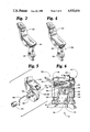
- FIG. 3 is a perspective view of one embodiment of a trigger member useful in the practice of this invention.
- FIG. 4 is a perspective view of an alternative embodiment of a trigger member useful in the practice of this invention.
- FIG. 5 is a fragmentary perspective exploded view of a portion of a bail support arm and associated elements.
- FIG. 6 is a top plan fragmentary view of the reel of FIG. 1 with the bail closed.
- FIG. 7 is an exploded perspective view of a portion of the detent mechanism of this invention.
- FIG. 8 is a fragmentary plan view of a partially disassembled reel with parts broken away.
- FIG. 9 is a fragmentary perspective view of FIG. 8 and showing a portion of the trip wire means of the present invention and showing a portion of the yoke in phantom.
- FIG. 10 is a fragmentary top plan detail of the detent mechanism of this invention with some parts cut away and some parts shown in phantom with the detent mechanism in the closed-bail position.
- FIG. 11 is a view of the parts of FIG. 10 in the open-bail position.
- FIG. 12 is a section taken along line 12--12 of FIG. 10.
- FIG. 13 is a view similar to FIG. 12 with parts in a stressed condition.
- Reel 8 has a frame 12 on which a spool 14 is mounted.
- a rotatable yoke 16 carries a wire bail 18 shown in a closed position in FIG. 1 and in an open position in FIG. 2.
- the closed position in FIG. 1 is a line rewinding position where a fishing line 20 is rewound by bail 18 on spool 14.
- bail 18 is in the open or line pay off position as shown in FIG. 2, line 20 is free to unwind from spool 14.
- line pay off may also occur, however it will be against the drag acting against rotation of spool 14.
- the line 20 may unwind from spool 14 without movement of spool 14.
- Reel 8 also has a detent mechanism 10 to hold bail 18 in one of the open and closed positions.
- Bail 18 may be moved from the closed position of FIG. 1 to the open position of FIG. 2 by actuation of trigger member 22 which operates against a bail support arm 24.
- Bail support arm 24 pivotably mounts one end of bail 18 to an adjacent portion 25 of yoke 16.
- the other end of bail 18 is mounted in pivoting relationship with an opposite portion 26 of yoke 16.
- Bail support arm 24 is pivoted about a fixed pivot or axis 28 (see FIGS. 5 and 6). Bail 18 may be opened and closed manually as well, if desired.
- trigger member 22 is pivotably or rotatably mounted to yoke 16 by screw 30 located in aperture 32.
- Trigger member 22 may have a rigid bearing surface 34 to engage a mating rigid bearing surface (not shown) on bail support arm 24 to drive bail support arm 24 from a first bail support arm position 35 to a second bail support arm position 37 as may also be seen in FIGS. 10 and 11.
- a roller may be interposed at the point of engagement between trigger member 22 and bail support arm 24.
- trigger member 22 may have a roller 38 mounted thereon in place of rigid bearing surface 34 (as shown in FIG. 3). As may be seen in FIG.
- bail support arm 24 may alternatively or additionally have a roller 36 mounted thereto by any conventional means such as an axle 40.
- trigger 22 drives bail support arm 24 through rolling contact between rollers 36 and 38, thus reducing friction and improving the ease of operating trigger 22. It is to be understood, however, that some benefit of reduced friction may be obtained in alternative embodiments using only one roller positioned on either the trigger 22 or the bail support arm 24 with a consequent reduction in cost and complexity. In a still further embodiment, a further reduction in cost and complexity may be achieved by eliminating any roller between trigger 22 and bail support arm 24.
- trigger member 22 is mounted on yoke 16 to one side of bail support arm pivot 28 and preferably engages bail support arm 24 on that side of pivot 28, thus avoiding unbalanced loading with consequent mechanical deflection inherent in designs which have a trigger mount on one side of the pivot and a trigger engagement with a support for the bail on the other side of the pivot.
- Bail support arm 24 also has a projection 42 (shown most clearly in FIG. 5) which preferably includes a sleeve bearing or roller 44 mounted thereon. Alternatively roller 44 may be omitted from projection 42 if desired, in which case projection 42 is preferably enlarged to the outer diameter of roller 44.
- Bail support arm 24 further has a recess 46 receiving a first extension 48 of a generally Z-shaped trip wire or trip member 50 as shown in FIG. 7. As may be seen in FIGS. 9, 10, 12 and 13, trip wire 50 further has a second extension 52 projecting through an aperture 54 in yoke 16. Trip wire 50 further has an intermediate portion 56 located in a recess 58 of yoke 16.
- Recess 58 carries member 50 and connects aperture 54 with an aperture 60 in yoke 16. All of trip wire extensions 48, 52 and intermediate portion 56 of trip wire 50 preferably lie substantially in a plane. Recess 58 and apertures 54 and 60 permit trip wire 50 to slide back and forth in recess 58 as may be seen most clearly in FIGS. 10 and 11.
- both the trip wire 50 and trigger member 22 are mounted on yoke 16 to the same side of the bail support arm pivot 28 to reduce or eliminate unbalanced loading and to thereby improve the "feel" of the detent mechanism 10 in operation.
- the contact between trigger member 22 and bail support arm 24 lies in the same plane as that of trip wire 50 also improving the "feel".
- FIG. 7 a drive shoe 62 is urged against bearing 44 by a cylindrical spring 64 (having a principal cylindrical axis 65) which acts against surface 66 of yoke 16.
- Spring 64 and drive shoe 62 drive bail support arm 24 to one of the two positions shown in FIGS. 10 and 11.
- FIG. 10 corresponds to the bail-closed or line rewinding position 35 of FIG. 1.
- FIG. 11 corresponds to the bail-open or line pay off position 37 of FIG. 2.
- Bail support arm 24 is rotatably mounted on yoke 16 at the fixed pivot 28 by headed axle 69.
- Axle 68 has a groove 70 which receives retaining ring 72.
- a cover 74 is secured to yoke 16 by a screw or other fastener 76.
- FIG. 10 corresponds to the bail-closed or line rewinding position 35 of FIG. 1.
- FIG. 11 corresponds to the bail-open or line pay off position 37 of FIG. 2.
- Bail support arm 24 is rot
- detent mechanism 10 having a bail support arm 24 for pivotably mounted the bail 18 about axis 28 between first and second bail positions on the yoke 16, spring 64 for biasing the bail support arm 24 with respect to yoke 16, and drive shoe or bail support arm follower 62 connected or interposed between spring 64 and projection 42 on bail support arm 24 for driving bail support arm 24 selectively toward one of the first and second arm positions 35, 37 (as shown in FIGS. 10 and 11) and away from a range of intermediate positions.
- the drive shoe 62 does not have any fixed pivot, but is slidingly positionable to a near over-center position 77 as shown in FIG.
- FIG. 10 shows a first side of an over-center position (not shown) while the bail support arm 24 is in the second bail support arm position 37, and a remote non-over-center position 78 as shown in FIG. 10 which is on a second side of the over-center position while the bail support arm 24 is in the first bail support arm position 35.
- Drive shoe 62 slides within portion 25 of yoke 16 to allow controlled deformation of spring 64 away from axis 65 of the cylindrical configuration.
- FIG. 10 shows spring 64 held in controlled deformation away from axis 65 when bail support arm 24 is in the first bail support arm position 35.
- FIG. 11 shows spring 64 compressed along cylindrical configuration axis 65 by drive shoe 62 when the bail support arm 24 is in the second bail support arm position 37.
- reel 8 has a hollow threaded shaft 80 which rotatably drives yoke 16.
- Reel 8 also has a reciprocating shaft 82 for reciprocating spool 14 along the axis of shaft 82.
- Shaft 82 is preferably free to rotate but is not driven, and may have a drag mechanism to retard line pay off with the bail closed.
- a stationary ramp 84 is secured to frame 12 and is preferably formed as an integral part of a bearing cover 86 for a yoke bearing (not shown) of reel 8.
- ramp 84 may be formed integral with frame 12.
- Bearing cover 86 concurrently acts as a shield for the yoke bearing.
- Ramp 84 is preferably formed of two sloping surfaces 88, 90 and is thus bidirectional.
- detent mechanism 10 The operation of detent mechanism 10 is as follows. Referring now again to FIG. 1, with the bail 18 in the closed-bail or line-rewinding position as shown in FIG. 1, trigger member 22 may be grasped and urged to engage bail support arm 24 to drive bail 18 from the line-rewinding to the line-pay off position shown in FIG. 2. Surface 34 (or alternatively roller 38) on member 22 engages bail support arm 24 preferably at roller 36 (see FIGS. 3-5) or at a corresponding rigid surface (not shown). As shown in FIG. 10, bail support arm 24 drives drive shoe 62 against spring 64 through projection 42 and roller 44. In the preferred practice of this invention, spring 64 is permitted to deform or buckle. The degree of deformation or buckling is controlled by drive shoe 62 as shown in FIGS. 10 and 11.
- bail 18 moves to the open-bail or line-pay off position as shown in FIG. 2.
- Spring 64 is compressed and brought into alignment with the principal cylindrical axis 65 of spring 64.
- pivotless drive shoe 62 is urged by biasing spring 64 to hold the bail 18 in an open-bail position (corresponding to the second bail support arm position 37 shown in FIG. 2) while the detent mechanism 10 is in the near-over-center position 77.
- ramp 84 drives bail support arm 24 from the line-pay off position 37 to the line-rewinding position 35 through the trip wire 50 carried by yoke 16. Since ramp 84 is bidirectional, trip wire 50 will drive bail support arm 24 from the line-pay off to the line-rewinding position for either direction of rotation of yoke 16.
- FIG. 13 A further feature of the detent mechanism is illustrated in FIG. 13.
- trip member 50 is sufficiently resilient to deform elastically as shown in FIG. 13 to prevent damage.
- the sliding drive shoe 62 retains trip wire 50 in yoke 16, while permitting wire 50 to slide in recess 58.
- first and second positions of the detent mechanism may be interchanged with respect to the open and closed bail positions.
Abstract
Description
Claims (22)
Priority Applications (1)
| Application Number | Priority Date | Filing Date | Title |
|---|---|---|---|
| US07/243,285 US4932616A (en) | 1988-09-12 | 1988-09-12 | Bail release mechanism for a spinning fishing reel |
Applications Claiming Priority (1)
| Application Number | Priority Date | Filing Date | Title |
|---|---|---|---|
| US07/243,285 US4932616A (en) | 1988-09-12 | 1988-09-12 | Bail release mechanism for a spinning fishing reel |
Publications (1)
| Publication Number | Publication Date |
|---|---|
| US4932616A true US4932616A (en) | 1990-06-12 |
Family
ID=22918128
Family Applications (1)
| Application Number | Title | Priority Date | Filing Date |
|---|---|---|---|
| US07/243,285 Expired - Fee Related US4932616A (en) | 1988-09-12 | 1988-09-12 | Bail release mechanism for a spinning fishing reel |
Country Status (1)
| Country | Link |
|---|---|
| US (1) | US4932616A (en) |
Cited By (10)
| Publication number | Priority date | Publication date | Assignee | Title |
|---|---|---|---|---|
| US5261628A (en) * | 1992-02-07 | 1993-11-16 | Abu Garcia Produktion Ab | Damping device in an open-face fishing reel of the fixed-spool type |
| US5312067A (en) * | 1991-05-07 | 1994-05-17 | Shimano Inc. | Spinning reel |
| US5613644A (en) * | 1995-01-30 | 1997-03-25 | Abu Ab | Bail mechanism in an open-face fishing reel of the fixed-spool type |
| DE19634296A1 (en) * | 1996-08-24 | 1997-04-24 | Erich Dipl Ing Ufer | Aircraft fan jet propulsion unit |
| US5667159A (en) * | 1992-07-15 | 1997-09-16 | Zebco Div. Of Brunswick Corporation | Trip system for a bail assembly on a fishing reel |
| KR20010091040A (en) * | 2000-04-10 | 2001-10-22 | 브런즈윅 코포레이션 | Trigger for actuating a bail assembly |
| US6729568B2 (en) * | 2001-04-16 | 2004-05-04 | Shimano, Inc. | Spinning reel bail tripping device |
| EP2002716A1 (en) * | 2007-06-15 | 2008-12-17 | Shimano Inc. | Reel unit for spinning reel |
| US20160174536A1 (en) * | 2014-12-19 | 2016-06-23 | Shimano Components (Malaysia) Sdn. Bhd. | Spinning reel |
| JP2019205360A (en) * | 2018-05-28 | 2019-12-05 | 株式会社シマノ | Spinning reel |
Citations (44)
| Publication number | Priority date | Publication date | Assignee | Title |
|---|---|---|---|---|
| US3233845A (en) * | 1962-08-23 | 1966-02-08 | Inamura Hachio | Spinning type fishing reel |
| US3342442A (en) * | 1965-01-11 | 1967-09-19 | Brantingson Sigurd | Fishing reel |
| JPS4919186A (en) * | 1972-06-14 | 1974-02-20 | ||
| US3946963A (en) * | 1974-08-01 | 1976-03-30 | Berkley & Company, Inc. | Drag assembly for spinning reels with fixed indicator bezel |
| US4005832A (en) * | 1974-09-09 | 1977-02-01 | Ryobi, Ltd. | Structure relating to bail arm of spinning reel for fishing |
| JPS5332191A (en) * | 1976-09-07 | 1978-03-27 | Toyoda Chuo Kenkyusho Kk | Production of insoluble phosphatase |
| US4095756A (en) * | 1975-12-27 | 1978-06-20 | Ryobi, Ltd. | Bail latching and releasing mechanism for open-spool spinning reel |
| US4098473A (en) * | 1976-03-04 | 1978-07-04 | Ryobi, Ltd. | Bail latching and releasing mechanism for spin fishing reel |
| US4098472A (en) * | 1976-03-03 | 1978-07-04 | Ryobi, Ltd. | Spin fishing reel with adjustable bail arm return spring |
| US4108392A (en) * | 1976-03-26 | 1978-08-22 | S.E.D.I.C. | Fishing reel |
| US4109880A (en) * | 1976-06-11 | 1978-08-29 | Ryobi Ltd. | Spinning reel having overrideable friction brake for preventing bail release |
| US4147313A (en) * | 1977-02-18 | 1979-04-03 | Ryobi Ltd. | Bail latching and releasing mechanism for spin fishing reel |
| JPS54101766A (en) * | 1978-01-13 | 1979-08-10 | Metallgesellschaft Ag | Removing of sulfur dioxide from sulfur dioxide containing gas |
| US4171108A (en) * | 1977-04-19 | 1979-10-16 | Shimano Industrial Company Limited | Spinning type fishing reel |
| JPS5536063A (en) * | 1978-09-08 | 1980-03-13 | Hitachi Ltd | Roll replacement device of rolling mill |
| US4196868A (en) * | 1978-08-11 | 1980-04-08 | Brunswick Corporation | Line guide for spinning reel |
| US4202508A (en) * | 1977-04-19 | 1980-05-13 | Shimano Industrial Company Limited | Spinning type fishing reel |
| US4222534A (en) * | 1978-02-04 | 1980-09-16 | Shimano Industrial Company, Limited | Fishing reel |
| US4279387A (en) * | 1978-12-18 | 1981-07-21 | Ryobi Ltd. | Bail latching and releasing mechanism for spinning reel |
| JPS56101767A (en) * | 1980-01-18 | 1981-08-14 | Mitsubishi Electric Corp | Semiconductor integrated circuit |
| JPS56157972A (en) * | 1980-04-30 | 1981-12-05 | Matsushita Electric Works Ltd | Inserting tool for e type snap ring |
| JPS56157973A (en) * | 1980-05-07 | 1981-12-05 | Yamaha Motor Co Ltd | Exchanging tool for tappet shim of four-stroke engine |
| JPS56157971A (en) * | 1980-05-02 | 1981-12-05 | Taiyou Hatsujiyou Seisakusho K | Oil pressure type switchgear for portable tool |
| JPS5731733A (en) * | 1980-08-01 | 1982-02-20 | Toyotomi Kogyo Co Ltd | Heating equipment |
| JPS5746782A (en) * | 1980-08-28 | 1982-03-17 | Chiyoda Chem Eng Construct Co | Sealing mechanism for floating roof of tank |
| US4337905A (en) * | 1978-04-07 | 1982-07-06 | Ryobi, Ltd. | Bail latching and releasing mechanism for spinning reel of outside spool type |
| US4350312A (en) * | 1977-08-05 | 1982-09-21 | Jean Masclet | Fishing reel |
| JPS57189370A (en) * | 1981-05-15 | 1982-11-20 | Nakamichi Corp | Operating device for tone arm |
| JPS588053A (en) * | 1981-07-07 | 1983-01-18 | Minoru Sekiya | Preparation of beta-aminonitrile |
| JPS5822538A (en) * | 1981-08-04 | 1983-02-09 | 株式会社東芝 | Automatic load regulator |
| JPS5870770A (en) * | 1981-10-22 | 1983-04-27 | 住友電気工業株式会社 | Coated carbon fiber |
| JPS5870769A (en) * | 1981-10-22 | 1983-04-27 | 住友電気工業株式会社 | Coated carbon fiber |
| US4389027A (en) * | 1981-02-11 | 1983-06-21 | Ryobi Limited | Bail arm reversing device fishing spinning reels |
| JPS58146465A (en) * | 1982-02-05 | 1983-09-01 | インペリアル・ケミカル・インダストリ−ズ・ピ−エルシ− | Liquid spray apparatus |
| US4403750A (en) * | 1979-04-09 | 1983-09-13 | Ryobi, Ltd. | Bail latching and releasing mechanism for spinning reel |
| US4427161A (en) * | 1981-05-23 | 1984-01-24 | Daiwa Seiko Inc. | Bail arm turning device for fishing spinning reel |
| US4502645A (en) * | 1981-07-28 | 1985-03-05 | Ryobi Limited | Fishing spinning reels |
| US4535952A (en) * | 1982-12-15 | 1985-08-20 | Abu Aktiebolag | Bail operating mechanism for fishing reels |
| US4562976A (en) * | 1982-06-22 | 1986-01-07 | Shimano Industrial Company Limited | Arm roller supporting device for a spinning reel |
| US4614314A (en) * | 1983-07-27 | 1986-09-30 | Shimano Industrial Company Limited | Spinning reel |
| US4676450A (en) * | 1984-01-06 | 1987-06-30 | Brunswick Corporation | Quick bail opening system for fishing reel |
| US4705228A (en) * | 1984-10-26 | 1987-11-10 | Ryobi Ltd. | Spinning reel having improved bail arm mechanism |
| US4747559A (en) * | 1985-05-09 | 1988-05-31 | Shimano Industrial Company Limited | Bail arm turning-over device for a fishing reel |
| US4848695A (en) * | 1985-04-19 | 1989-07-18 | Daiwa Seiko Inc. | Spinning reel for fishing |
-
1988
- 1988-09-12 US US07/243,285 patent/US4932616A/en not_active Expired - Fee Related
Patent Citations (46)
| Publication number | Priority date | Publication date | Assignee | Title |
|---|---|---|---|---|
| US3233845A (en) * | 1962-08-23 | 1966-02-08 | Inamura Hachio | Spinning type fishing reel |
| US3342442A (en) * | 1965-01-11 | 1967-09-19 | Brantingson Sigurd | Fishing reel |
| US3342442B1 (en) * | 1965-01-11 | 1991-10-29 | ||
| JPS4919186A (en) * | 1972-06-14 | 1974-02-20 | ||
| US3946963A (en) * | 1974-08-01 | 1976-03-30 | Berkley & Company, Inc. | Drag assembly for spinning reels with fixed indicator bezel |
| US4005832A (en) * | 1974-09-09 | 1977-02-01 | Ryobi, Ltd. | Structure relating to bail arm of spinning reel for fishing |
| US4095756A (en) * | 1975-12-27 | 1978-06-20 | Ryobi, Ltd. | Bail latching and releasing mechanism for open-spool spinning reel |
| US4098472A (en) * | 1976-03-03 | 1978-07-04 | Ryobi, Ltd. | Spin fishing reel with adjustable bail arm return spring |
| US4098473A (en) * | 1976-03-04 | 1978-07-04 | Ryobi, Ltd. | Bail latching and releasing mechanism for spin fishing reel |
| US4108392A (en) * | 1976-03-26 | 1978-08-22 | S.E.D.I.C. | Fishing reel |
| US4109880A (en) * | 1976-06-11 | 1978-08-29 | Ryobi Ltd. | Spinning reel having overrideable friction brake for preventing bail release |
| JPS5332191A (en) * | 1976-09-07 | 1978-03-27 | Toyoda Chuo Kenkyusho Kk | Production of insoluble phosphatase |
| US4147313A (en) * | 1977-02-18 | 1979-04-03 | Ryobi Ltd. | Bail latching and releasing mechanism for spin fishing reel |
| US4202508A (en) * | 1977-04-19 | 1980-05-13 | Shimano Industrial Company Limited | Spinning type fishing reel |
| US4171108A (en) * | 1977-04-19 | 1979-10-16 | Shimano Industrial Company Limited | Spinning type fishing reel |
| US4350312A (en) * | 1977-08-05 | 1982-09-21 | Jean Masclet | Fishing reel |
| JPS54101766A (en) * | 1978-01-13 | 1979-08-10 | Metallgesellschaft Ag | Removing of sulfur dioxide from sulfur dioxide containing gas |
| US4222534A (en) * | 1978-02-04 | 1980-09-16 | Shimano Industrial Company, Limited | Fishing reel |
| US4337905A (en) * | 1978-04-07 | 1982-07-06 | Ryobi, Ltd. | Bail latching and releasing mechanism for spinning reel of outside spool type |
| US4196868A (en) * | 1978-08-11 | 1980-04-08 | Brunswick Corporation | Line guide for spinning reel |
| JPS5536063A (en) * | 1978-09-08 | 1980-03-13 | Hitachi Ltd | Roll replacement device of rolling mill |
| US4279387A (en) * | 1978-12-18 | 1981-07-21 | Ryobi Ltd. | Bail latching and releasing mechanism for spinning reel |
| US4403750A (en) * | 1979-04-09 | 1983-09-13 | Ryobi, Ltd. | Bail latching and releasing mechanism for spinning reel |
| JPS56101767A (en) * | 1980-01-18 | 1981-08-14 | Mitsubishi Electric Corp | Semiconductor integrated circuit |
| JPS56157972A (en) * | 1980-04-30 | 1981-12-05 | Matsushita Electric Works Ltd | Inserting tool for e type snap ring |
| JPS56157971A (en) * | 1980-05-02 | 1981-12-05 | Taiyou Hatsujiyou Seisakusho K | Oil pressure type switchgear for portable tool |
| JPS56157973A (en) * | 1980-05-07 | 1981-12-05 | Yamaha Motor Co Ltd | Exchanging tool for tappet shim of four-stroke engine |
| JPS5731733A (en) * | 1980-08-01 | 1982-02-20 | Toyotomi Kogyo Co Ltd | Heating equipment |
| JPS5746782A (en) * | 1980-08-28 | 1982-03-17 | Chiyoda Chem Eng Construct Co | Sealing mechanism for floating roof of tank |
| US4389027A (en) * | 1981-02-11 | 1983-06-21 | Ryobi Limited | Bail arm reversing device fishing spinning reels |
| JPS57189370A (en) * | 1981-05-15 | 1982-11-20 | Nakamichi Corp | Operating device for tone arm |
| US4427161A (en) * | 1981-05-23 | 1984-01-24 | Daiwa Seiko Inc. | Bail arm turning device for fishing spinning reel |
| JPS588053A (en) * | 1981-07-07 | 1983-01-18 | Minoru Sekiya | Preparation of beta-aminonitrile |
| US4502645A (en) * | 1981-07-28 | 1985-03-05 | Ryobi Limited | Fishing spinning reels |
| JPS5822538A (en) * | 1981-08-04 | 1983-02-09 | 株式会社東芝 | Automatic load regulator |
| JPS5870769A (en) * | 1981-10-22 | 1983-04-27 | 住友電気工業株式会社 | Coated carbon fiber |
| JPS5870770A (en) * | 1981-10-22 | 1983-04-27 | 住友電気工業株式会社 | Coated carbon fiber |
| JPS58146465A (en) * | 1982-02-05 | 1983-09-01 | インペリアル・ケミカル・インダストリ−ズ・ピ−エルシ− | Liquid spray apparatus |
| US4562976A (en) * | 1982-06-22 | 1986-01-07 | Shimano Industrial Company Limited | Arm roller supporting device for a spinning reel |
| US4535952A (en) * | 1982-12-15 | 1985-08-20 | Abu Aktiebolag | Bail operating mechanism for fishing reels |
| US4614314A (en) * | 1983-07-27 | 1986-09-30 | Shimano Industrial Company Limited | Spinning reel |
| US4676450A (en) * | 1984-01-06 | 1987-06-30 | Brunswick Corporation | Quick bail opening system for fishing reel |
| US4676450B1 (en) * | 1984-01-06 | 1991-06-25 | Quick bail opening system for fishing reel | |
| US4705228A (en) * | 1984-10-26 | 1987-11-10 | Ryobi Ltd. | Spinning reel having improved bail arm mechanism |
| US4848695A (en) * | 1985-04-19 | 1989-07-18 | Daiwa Seiko Inc. | Spinning reel for fishing |
| US4747559A (en) * | 1985-05-09 | 1988-05-31 | Shimano Industrial Company Limited | Bail arm turning-over device for a fishing reel |
Cited By (15)
| Publication number | Priority date | Publication date | Assignee | Title |
|---|---|---|---|---|
| US5312067A (en) * | 1991-05-07 | 1994-05-17 | Shimano Inc. | Spinning reel |
| US5261628A (en) * | 1992-02-07 | 1993-11-16 | Abu Garcia Produktion Ab | Damping device in an open-face fishing reel of the fixed-spool type |
| US5667159A (en) * | 1992-07-15 | 1997-09-16 | Zebco Div. Of Brunswick Corporation | Trip system for a bail assembly on a fishing reel |
| US5613644A (en) * | 1995-01-30 | 1997-03-25 | Abu Ab | Bail mechanism in an open-face fishing reel of the fixed-spool type |
| DE19634296A1 (en) * | 1996-08-24 | 1997-04-24 | Erich Dipl Ing Ufer | Aircraft fan jet propulsion unit |
| DE19634296C2 (en) * | 1996-08-24 | 1999-04-22 | Erich Dipl Ing Ufer | Blower engine for aircraft with facilities for boundary layer extraction |
| KR20010091040A (en) * | 2000-04-10 | 2001-10-22 | 브런즈윅 코포레이션 | Trigger for actuating a bail assembly |
| US6729568B2 (en) * | 2001-04-16 | 2004-05-04 | Shimano, Inc. | Spinning reel bail tripping device |
| EP2002716A1 (en) * | 2007-06-15 | 2008-12-17 | Shimano Inc. | Reel unit for spinning reel |
| US20080308663A1 (en) * | 2007-06-15 | 2008-12-18 | Shimano Inc. | Reel unit for spinning reel |
| US7607602B2 (en) | 2007-06-15 | 2009-10-27 | Shimano Inc. | Reel unit for spinning reel |
| CN101322484B (en) * | 2007-06-15 | 2011-12-14 | 株式会社岛野 | Reel unit for spinning reel |
| US20160174536A1 (en) * | 2014-12-19 | 2016-06-23 | Shimano Components (Malaysia) Sdn. Bhd. | Spinning reel |
| US9770016B2 (en) * | 2014-12-19 | 2017-09-26 | Shimano Components (Malaysia) Sdn. Bhd. | Spinning reel |
| JP2019205360A (en) * | 2018-05-28 | 2019-12-05 | 株式会社シマノ | Spinning reel |
Similar Documents
| Publication | Publication Date | Title |
|---|---|---|
| US4932616A (en) | Bail release mechanism for a spinning fishing reel | |
| US5186412A (en) | Spool braking force switching device for fishing reel | |
| US4491885A (en) | Magnetic recording/playback device | |
| US4031556A (en) | Mode changeover apparatus for recorder/player | |
| TW467723B (en) | Bail tripping device for spinning reel | |
| US4824046A (en) | Clutch mechanism for use in fishing reels | |
| US5988546A (en) | Fishing reel tension bail mechanism | |
| US4389690A (en) | Magnetic tape cassette including a locking mechanism | |
| DE2713267A1 (en) | TAPE RECORDER | |
| US5947397A (en) | Compact spinning reel having inclined pivoting axis | |
| US3652030A (en) | Tape reeling mechanism on video tape recorder | |
| US4923140A (en) | Bail reversing apparatus for fishing spinning reels | |
| US5393006A (en) | Fishing reel | |
| US3142454A (en) | Spinning reel with line brake | |
| JPH104839A (en) | Spinning reel for fishing | |
| JPH0447372B2 (en) | ||
| US6045074A (en) | Actuating system for changing a fishing reel from a retrieve state into a cast state | |
| KR940005822Y1 (en) | Guide arm and pinch arm assembly of vcr | |
| KR970001351B1 (en) | Equipment for turning round bail arm of a reel for fishing | |
| JPS624949Y2 (en) | ||
| US5519550A (en) | Tape cassette adapter for converting a compact tape cassette to a standard size tape cassette for application in a general video-tape player | |
| JP3358781B2 (en) | Spinning reel for fishing | |
| JP2919737B2 (en) | Spinning reel | |
| US3161369A (en) | Re-winding device for photographic cameras | |
| KR100226421B1 (en) | The antibacklash device in the fishing reel |
Legal Events
| Date | Code | Title | Description |
|---|---|---|---|
| AS | Assignment |
Owner name: BERKLEY, INC., ONE BERKLEY DR., SPIRIT LAKE, IA 51 Free format text: ASSIGNMENT OF ASSIGNORS INTEREST.;ASSIGNORS:MC MICKLE, ROBERT L.;BENIT, BRADLEY J.;GRICE, STEVEN L.;REEL/FRAME:004956/0218 Effective date: 19880908 Owner name: BERKLEY, INC., A CORP. OF IA,IOWA Free format text: ASSIGNMENT OF ASSIGNORS INTEREST;ASSIGNORS:MC MICKLE, ROBERT L.;BENIT, BRADLEY J.;GRICE, STEVEN L.;REEL/FRAME:004956/0218 Effective date: 19880908 |
|
| FPAY | Fee payment |
Year of fee payment: 4 |
|
| FPAY | Fee payment |
Year of fee payment: 8 |
|
| AS | Assignment |
Owner name: HARRIS TRUST AND SAVINGS BANK, ILLINOIS Free format text: SECURITY INTEREST;ASSIGNOR:BERKLEY INC.;REEL/FRAME:010942/0073 Effective date: 20000204 |
|
| REMI | Maintenance fee reminder mailed | ||
| LAPS | Lapse for failure to pay maintenance fees | ||
| STCH | Information on status: patent discontinuation |
Free format text: PATENT EXPIRED DUE TO NONPAYMENT OF MAINTENANCE FEES UNDER 37 CFR 1.362 |
|
| FP | Expired due to failure to pay maintenance fee |
Effective date: 20020612 |
|
| AS | Assignment |
Owner name: PURE FISHING, INC., IOWA Free format text: RELEASE AND REASSIGNMENT;ASSIGNOR:HARRIS TRUST AND SAVINGS BANK, AS AGENT;REEL/FRAME:014306/0112 Effective date: 20030618 |