US4716347A - Oscillation reducing apparatus for rotary compressor - Google Patents
Oscillation reducing apparatus for rotary compressor Download PDFInfo
- Publication number
- US4716347A US4716347A US06/839,735 US83973586A US4716347A US 4716347 A US4716347 A US 4716347A US 83973586 A US83973586 A US 83973586A US 4716347 A US4716347 A US 4716347A
- Authority
- US
- United States
- Prior art keywords
- compressor
- motor
- load torque
- torque
- inverter
- Prior art date
- Legal status (The legal status is an assumption and is not a legal conclusion. Google has not performed a legal analysis and makes no representation as to the accuracy of the status listed.)
- Expired - Lifetime
Links
Images


Classifications
-
- H—ELECTRICITY
- H02—GENERATION; CONVERSION OR DISTRIBUTION OF ELECTRIC POWER
- H02M—APPARATUS FOR CONVERSION BETWEEN AC AND AC, BETWEEN AC AND DC, OR BETWEEN DC AND DC, AND FOR USE WITH MAINS OR SIMILAR POWER SUPPLY SYSTEMS; CONVERSION OF DC OR AC INPUT POWER INTO SURGE OUTPUT POWER; CONTROL OR REGULATION THEREOF
- H02M7/00—Conversion of ac power input into dc power output; Conversion of dc power input into ac power output
- H02M7/42—Conversion of dc power input into ac power output without possibility of reversal
- H02M7/44—Conversion of dc power input into ac power output without possibility of reversal by static converters
- H02M7/48—Conversion of dc power input into ac power output without possibility of reversal by static converters using discharge tubes with control electrode or semiconductor devices with control electrode
- H02M7/53—Conversion of dc power input into ac power output without possibility of reversal by static converters using discharge tubes with control electrode or semiconductor devices with control electrode using devices of a triode or transistor type requiring continuous application of a control signal
- H02M7/537—Conversion of dc power input into ac power output without possibility of reversal by static converters using discharge tubes with control electrode or semiconductor devices with control electrode using devices of a triode or transistor type requiring continuous application of a control signal using semiconductor devices only, e.g. single switched pulse inverters
- H02M7/5387—Conversion of dc power input into ac power output without possibility of reversal by static converters using discharge tubes with control electrode or semiconductor devices with control electrode using devices of a triode or transistor type requiring continuous application of a control signal using semiconductor devices only, e.g. single switched pulse inverters in a bridge configuration
- H02M7/53871—Conversion of dc power input into ac power output without possibility of reversal by static converters using discharge tubes with control electrode or semiconductor devices with control electrode using devices of a triode or transistor type requiring continuous application of a control signal using semiconductor devices only, e.g. single switched pulse inverters in a bridge configuration with automatic control of output voltage or current
- H02M7/53873—Conversion of dc power input into ac power output without possibility of reversal by static converters using discharge tubes with control electrode or semiconductor devices with control electrode using devices of a triode or transistor type requiring continuous application of a control signal using semiconductor devices only, e.g. single switched pulse inverters in a bridge configuration with automatic control of output voltage or current with digital control
-
- G—PHYSICS
- G05—CONTROLLING; REGULATING
- G05D—SYSTEMS FOR CONTROLLING OR REGULATING NON-ELECTRIC VARIABLES
- G05D19/00—Control of mechanical oscillations, e.g. of amplitude, of frequency, of phase
- G05D19/02—Control of mechanical oscillations, e.g. of amplitude, of frequency, of phase characterised by the use of electric means
Definitions
- the present invention relates to a compressor to be driven by a motor, and, more particularly, to a compressor provided with a vibration reducing device which can reduce the vibration caused by the load torque fluctuation of the compressor.
- the motion balance is almost completely governed to remove the usual vibrations caused by the load torque fluctuations.
- the rotary portion of the rotary compressor is varied in rotation by the variations in load torque so that the twisting oscillations are caused in the compressor by the reaction force of the rotation variation. Accordingly, once the type of rotary compressor and load torque variation pattern for the compressor are determined, twist oscillations which may be almost constant are formulated to be caused in accordance with the determination.
- a dynamic oscillation absorber is additionally provided on the compressor container as disclosed in, for example, Japanese Patent Publication (unexamined) Tokkaisho No. 59-50244.
- the primary natural oscillation number of the dynamic oscillation absorber is made almost consistent with the rotation frequency or power supply frequency of the compressor to absorb the oscillations which are caused by the load torque changes.
- the inertia movement of the rotation portion of the rotary compressor is made larger to render the rotary change of the rotation portion smaller, thereby reducing the oscillations which are caused by the load torque changes.
- any one of the conventional art devices are not effective measures with respect to the oscillations which are caused by the load torque changes, because they are restrictive in their oscillation reduction, and therefore ineffective for oscillation reduction.
- the present inventor investigates the movement of the rotation portion of the rotary compressor.
- the movement with respect to the amplitude of a twisting vibration of the compressor in a direction of the rotary shaft thereof will be described by the following equation.
- ⁇ s rotary angle with respect to the amplitude of twisting vibration in a direction of the rotary shaft of the compressor
- Ks spring constant of the support portion for the compressor in a direction of the rotary shaft
- ⁇ r angular velocity of the rotational portion of the compressor
- an object of the present invention is, in a rotary compressor provided with a motor to be controlled by an inverter, to vary the power supply frequency or impressed voltage during one rotation of the motor in accordance with the changes in the load torque to make the production torque of the motor correspond to the changes in the load torque so as to fundamentally and effectively reduce the oscillations which are caused by the load torque changes.
- the solving means of the present invention is provided with an inverter for varying the power supply frequency and the impressed voltage of the induction motor of the rotary compressor, a load torque estimating means for estimating the load torque during one rotation of the rotary compressor, a controlling means for receiving the output of the load torque estimating means and controlling the inverter so that the power supply frequency and impressed voltage of the induction motor are variably controlled in accordance with the load torque during one rotation.
- the power supply or impressed voltage of the motor is varied by the inverter in accordance with the load torque during one rotation to vary the production torque of the motor so that the variation in the load torque corresponds with the variation in the motor production torque so as to control the rotation variation of the rotary portion.
- FIG. 1 is a cross-sectional view of a compressor in accordance with one embodiment of the present invention
- FIG. 2 is a cross-sectional view taken along a line II--II of FIG. 1;
- FIG. 3 is a block diagram of an electric circuit constituting a vibration reducing device for use in the compressor of FIG. 1;
- FIG. 4 is a graph showing a fundamental pattern of load torque employed in the circuit of FIG. 3;
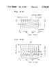
- FIGS. 5 and 6, (a) and (b), are graphs showing electric signals of outputs derived from components in the circuit of FIG. 3, respectively;
- FIGS. 7 and 8, (a) and (b), are graphs showing wave-forms of signals relating to the operation of the compressor of FIG. 1, respectively;
- FIG. 9 is a view similar to FIG. 3, providing additional components to the circuit of FIG. 3;
- FIGS. 10, (a) and (b), is a graph showing electric signals of outputs derived from components in the circuit of FIG. 9.
- the rotary compressor 1 comprises a compressor unit 10, a DC motor 20 of a brushless type for driving the compressor unit 10, and a circuit means 30 for controlling the driving condition of the motor 20 on the application of electric power from an AC power source 31 to the motor 20 therethrough.
- the compressor unit 10 includes a cylinder 12 provided with a pair of cylinder heads 13 covered at the openings of the cylinder 12 at both sides thereof to form a cylinder chamber 14 therein having a suction port 15 and a discharge portion 16, a rotator 17 accommodated within the cylinder chamber 14 to be rotatable eccentrically together with a crank shaft 18 of which both ends are journalled on the cylinder heads 13, and a movable blade 19 for partitioning a space disposed between the cylinder chamber 14 and rotator 16 into two sections, a suction section connected to the suction port 15 and a discharge section connected to the discharge port 16 so as to perform the compression operation for gas which is drawing in at the suction section and taking out from the discharge section.
- the compressor unit 10 is accommodated fixedly within a casing 2 together with the motor 20.
- the motor 20 is formed of a synchronous type having a stator 22 of windings provided fixedly within the casing 2, and a rotor 23 made by permanent magnet to be rotatable against the stator 22 together with the crank shaft 18 of the compressor unit 10 under control of the circuit means 30.
- the rotator 17 of the compressor unit 10 is driven in synchronous relationship with the rotation of the motor 20, for instance, in such a state that the rotor 23 is connected directly to the crank shaft 18.
- the circuit means 30 includes the AC power source 31, a rectifying circuit 32, a smoothing circuit 33, an inverter circuit 34 consisting of a transistor commutator for distributing the direct current supplied from the AC power source 31 through the rectifying circuit 32 and smoothing circuit 33 to the respective windings 22 of the motor 20 to drive the compressor unit 10, and a control circuit 35 for controlling the driving condition of the inverter circuit 34.
- the inverter circuit therefore changes a DC current output from the rectifying circuit 32 into an AC current by means of the control circuit 35, and the synchronous motors 20 is driven by the AC current output from the inverter circuit 34.
- the control circuit 35 includes a switching signal generating circuit 41 for generating switching signals of a pulse width modulated type, and a compensating circuit 61 for modifying the switching signals according to the load fluctuations of the compressor unit in a manner as described hereinafter.
- the switching signal generating circuit 41 includes a clock pulse generator 42 for generating clock pulse signals in train, a carrier-wave generator 43 for generating a high frequency current-wave for carrying a wave-signal in succession, as shown in FIG. 5(a), a first setting means 44 for introducing a frequency adjusting signal, a second setting means 45 for introducing a voltage-amplitude adjusting signal, a frequency divider 46 for outputting signals having a frequency lower than that of the frequency adjusting signal of the first setting means 44 on the basis of clock pulse signals, a ⁇ generator 47 for outputting signals of angles on the basis of signals of the frequency divider, a standard sine-wave generator 48 for outputting a sinusoidal-wave, as shown in FIG.
- a comparator 49 for outputting signals, as shown in FIG. 5(b) in comparison between the high frequency current-wave of the carrier-wave generator 43 and the sinusoidal-wave of the standard sine-wave generator 48, a position detector 51 for detecting a given position of the compressor unit to output a position signal with respect to the angle of the crank shaft 18, and a switching signal generator 52 for outputting switching signals to the inverter circuit 34 upon receiving the comparison signals from the comparator 49 and the position signal from the position detector 51.
- the first and second setting means 44 and 45 respectively, are adapted to output the respective adjusting signals with respect to frequency and voltage-amplitude corresponding to the difference between an actual value and a standard value relating to the driving condition of the compressor unit 10, for instance, an actual room temperature to be detected for operating the compressor unit 10 and a normal standard room temperature to be set beforehand through experience.
- the operation of the inverter circuit 34 is controlled by the switching signal generator 52 to drive the motor 20 in accordance with voltage of the AC power source modified by the switching signals of the switching signal generator 52.
- the ⁇ generator 47 outputs angle signals ⁇ relating to the frequency adjusting signal to be inputted from the frequency divider 46, and the second setting means 45 outputs a voltage-amplitude adjusting signal of constant voltage V
- the standard sine-wave generator 48 outputs a sinusoidal-wave of V cos ⁇
- the switching signal generator 52 outputs switching signals corresponding to the sinusoidal-wave of V cos ⁇ in relation to the crank angle as shown with graphs of FIGS.
- the compensating circuit 61 is provided in association with the switching signal generating circuit 41 in order to reduce the value difference between the generating torque of the motor 20 and the load torque of the compressor unit 10.
- the compensating circuit 61 includes a current detector 62 for detecting electric current being fed from the inverter 34 to the motor 20, memory means 63 for storing a fundamental portion of the load torque to be preset in accordance with the result of experiments conducted in relation to variations between crank angles of the crank shaft 18 and load torques of the compressor unit 10 under various conditions of the suction pressure and discharge pressure of the compressor unit 10 to be employed within a range of actual usage of the compressor unit 10, a calculating circuit 64 including a microcomputer for outputting, in relation to the crank angles, a compensating wave of load torque to closely resemble the actual load torque of the compressor unit 10 upon the influence of compensating values proportional to the electric current detected by the current detector 62 onto the fundamental pattern of the load torque of the memory means 63, a converter 65 for outputting, in relation to the crank angles, compensating values of voltage under taking the advantages of the compensating wave of load torque from the calculating circuit 64 by means of a gain K which is obtained as a constant value for changing the load torque to the voltage in accordance with the
- the fundamental pattern of load torque to be stored within the memory means 63 is one of the highest frequency in general use of the compressor 1 to be selected from the various patterns, as shown with graphs (a), (b), (d) and (e) of FIG. 4, of the crank angles and load torque obtained in relation to the various conditions of the suction pressure and discharge pressure of the compensator unit.
- the various patterns of load torque obtained by experiments resemble each other as like figures each depending upon different values of load torque at a certain crank angle, as shown in FIG. 4, so that supposed patterns of load torque closely resembling the respective various patterns can be obtained through the fundamental pattern multiplied by a corresponding function of constant value for adjusting to the respective pattern.
- the figure of one fundamental pattern is almost similar to the other patterns and, therefore, a pattern relating to either of a mean value, maximum value or minimum value of load torque may be employed as the fundamental pattern.
- the driving condition of the motor 20 is modified through the control circuit 35 to generate an output torque corresponding to the variation of the load torque of the compressor unit 10.
- the position detector 51 is usually adapted to detect the starting point, i.e., the zero angle of the crank shaft 18 of the compressor unit 10, while the current detector 62 is always applied to detect the electric current being fed from the inverter circuit 34 to the motor 20, as shown with the graph of FIG. 7(a).
- the output of the position detector 51 is employed as a signal for synchronizing the compressor unit 10 with the operation of the control circuit 35 for the motor 20 depending upon the output of the current detector 62, and the output of the current detector 62 being inputted into the calculating circuit to calculate a mean value of load torque for the compressor unit 10 for a period of each of one rotation of the motor 20.
- the carrier wave generator 43 outputs a carrier wave as shown with the graph of FIG. 6(a), and the first setting means 44 outputs a sine wave as shown with the graph of FIG. 5(a).
- the memory means 48 is operated to store a fundamental pattern of load torques in relation to crank angles as shown with graph (c) of FIG. 4, and constant values, such as, for instance, 150 V and 0.18 V/Nm are set within the second setting means 45 and converter 65, respectively.
- the standard sine-wave generator 48 outputs a modified sine-wave of (V+ ⁇ V( ⁇ ) cos ⁇ , as shown with graphs Vu-0, Vv-0, Vw-0 of FIG. 6(a), and the comparator 49 generates pulse signals, as shown with graphs of FIG. 6(b).
- the inverter circuit 34 is controlled by a wave signal of voltage, as shown with a graph of FIG.
- the voltage to be applied to the motor 20 through the inverter circuit is modified by the modified sine-wave generated from the control circuit in order to fluctuate the torque generated from the motor 20 in accordance with the changing of load torque necessary for the compressor unit 10 for each of its one revolution, whereby the generated torque of the motor 20 and the load torque of the compressor unit 10 are too close to each other to suppress the rotational fluctuation of the compressor 1 as well as the twisting vibration thereof.
- FIGS. 7 and 9 respectively show graphs of the voltage V, V+ ⁇ V applied from the inverter circuit 34 to the motor 20, the generating torque of the motor 20, the load torque of the compressor 10, and the rotational speed of the compressor 1.
- FIG. 7 is related to the device of the present invention providing the compensating circuit.
- FIG. 8 is related to a device without the compensating circuit.
- FIG. 8(b) the load torque T L necessary for compression of the compressor is shown with a curve of T L having a large fluctuation of between 0 to 16 Nm for one revolution of the compressor and the generating torque of the motor is shown with a curve T M having almost a constant value without any fluctuation, resulting in that the rotational fluctuation of the rotation speed with respect to the rotational components is generated, as shown with a curve of ⁇ r, to be caused by the difference between the curves T L and T M with the amount of amplitude of 1.8 Hz in addition to the generation of the twisting vibration of the compressor.
- the generating torque T M of the motor is modified to fluctuate the approach toward the curve of the load torque T L in synchronization with the driving condition of the compressor, whereby the rotational fluctuation of the rotational speed ⁇ r is suppressed under the influence of a narrow gap between the curves T L and T M with the amount of amplitude of 0.32 Hz, which is about one-fifth less in comparison with that of FIG. 8(b). Accordingly, it is clear that by the employment of the compensating circuit of the present invention, the rotational fluctuation and twisting vibration of the compressor are reduced to a great extent to drive the compressor in a stable condition.
- the above embodiment of the present invention is described with respect to the vibration reducing device for use in a rotary compressor by providing a compensating circuit which generates a voltage-amplitude adjusting signal for modifying the applied voltage to the motor, but it can, also, be done to obtain the same result by the employment of the other compensating circuits of types relating to frequency modulation, phase modulation, and the combination of amplitude modulation, frequency modulation and phase modulation.
- a compensating circuit in combination with amplitude modulation and frequency modulation another converter 71 and adjustable means 72 are added into the control circuit 35 of the embodiment of FIG. 3.
- the adjustable means 72 is provided between the ⁇ generator 47 and standard sine-wave generator 48, and the converter 71 is provided between the calculating circuit 64 and the adjustable means 72, the output ⁇ of the ⁇ generator 47 being adapted to modify by the output ⁇ T L ( ⁇ ) of the calculating circuit 64 through the converter 71 which converts the output of the calculating circuit 64 to the frequency ⁇ ( ⁇ ) by means of another gain K 2 .
- the gain K 2 is obtained as a constant value for changing the load torque to a frequency in accordance with the actual driving condition of the compressor.
- the standard sine-wave generator 48 Upon receiving the output ( ⁇ + ⁇ ( ⁇ )t) from the adjustable means 72 in addition to the output (V+ ⁇ V( ⁇ )) of the adjustable means 66, the standard sine-wave generator 48 outputs another modified sine-wave [(V+ ⁇ V( ⁇ ) ⁇ cos ( ⁇ + ⁇ ( ⁇ )t) ] as shown with graphs of FIG. 10(a), and the comparator 49 generates pulse signals, as shown with graphs of FIG. 10(b). Accordingly, the inverter circuit 34 is controlled by a wave signal of voltage regulated in combination of amplitude modulation and frequency modulation, resulting in that the applied voltage to the motor is adjusted to follow the changing amplitude and frequency with respect to the driving condition of the compressor so as to make it close to the load torque of the compressor unit.
- the generating torque of the motor may be varied in accordance with the fluctuation of the load torque to control the rotation variation of the rotation portion of the compressor.
- the position detector is adapted to synchronize rotational angles between the mechanical components and electrical circuits, and can be formed as various types such as the employment of hole element, high frequency vibrator, counter electromotive force relay and the like. Therefore, unless otherwise such changes and modifications depart from the scope of the present invention, they should be construed as included therein.
Abstract
Description
Is·(d.sup.2 θs/dt.sup.2)+Ks·θs=T.sub.M -T.sub.L (i)
Ir(dωr/dt)=T.sub.M -T.sub.L (ii)
Claims (9)
Applications Claiming Priority (2)
| Application Number | Priority Date | Filing Date | Title |
|---|---|---|---|
| JP60052947A JPS61211553A (en) | 1985-03-15 | 1985-03-15 | Vibration damping device for rotary compressor |
| JP60-52947 | 1985-03-15 |
Publications (1)
| Publication Number | Publication Date |
|---|---|
| US4716347A true US4716347A (en) | 1987-12-29 |
Family
ID=12929065
Family Applications (1)
| Application Number | Title | Priority Date | Filing Date |
|---|---|---|---|
| US06/839,735 Expired - Lifetime US4716347A (en) | 1985-03-15 | 1986-03-14 | Oscillation reducing apparatus for rotary compressor |
Country Status (2)
| Country | Link |
|---|---|
| US (1) | US4716347A (en) |
| JP (1) | JPS61211553A (en) |
Cited By (22)
| Publication number | Priority date | Publication date | Assignee | Title |
|---|---|---|---|---|
| EP0293915A2 (en) * | 1987-06-03 | 1988-12-07 | Hitachi, Ltd. | Inverter control apparatus |
| US4864209A (en) * | 1986-10-29 | 1989-09-05 | Fanuc Ltd. | Negative feedback control system |
| US4963804A (en) * | 1989-07-10 | 1990-10-16 | Westinghouse Electric Corp. | Apparatus and method for reducing vibration of rotating machinery |
| US5075607A (en) * | 1986-10-08 | 1991-12-24 | Hitachi, Ltd. | Method and apparatus for operating vacuum cleaner |
| US5126642A (en) * | 1991-01-31 | 1992-06-30 | Ranco Incorporated Of Delaware | Variable speed motor control |
| US5258694A (en) * | 1989-12-15 | 1993-11-02 | Alps Electric Co., Ltd. | Control device for ultrasonic motor |
| US5359269A (en) * | 1993-05-13 | 1994-10-25 | Hughes Aircraft Company | Torque oscillation compensation using torque transducer feedback |
| EP0652632A2 (en) * | 1993-10-08 | 1995-05-10 | Sawafuji Electric Co., Ltd. | Power supply for vibrating compressors |
| AU664786B2 (en) * | 1993-01-21 | 1995-11-30 | Fujitsu General Limited | Control device for air conditioner |
| US5532569A (en) * | 1987-06-03 | 1996-07-02 | Hitachi, Ltd. | Inverter control apparatus |
| US6002218A (en) * | 1992-11-20 | 1999-12-14 | Fujitsu General Limited | Control device for air conditioner |
| US6393383B1 (en) * | 1999-08-11 | 2002-05-21 | Toyota Jidosha Kabushi Kaisha | Setting apparatus and method for identification signal |
| EP1411405A2 (en) * | 2002-09-30 | 2004-04-21 | Alps Electric Co., Ltd. | Force imparting apparatus |
| EP1561945A2 (en) * | 2004-02-04 | 2005-08-10 | Clipper Windpower Technology, Inc. | Variable speed distributed drive train wind turbine system |
| US20100119378A1 (en) * | 2007-02-28 | 2010-05-13 | Daikin Industries, Ltd. | Rotary compressor |
| US20120235604A1 (en) * | 2011-03-15 | 2012-09-20 | Kabushiki Kaisha Toyota Jidoshokki | Inverter device of rotating electrical machine, and driving method for rotating electrical machine |
| US8794941B2 (en) | 2010-08-30 | 2014-08-05 | Oscomp Systems Inc. | Compressor with liquid injection cooling |
| US20150054437A1 (en) * | 2013-08-23 | 2015-02-26 | Kabushiki Kaisha Toshiba | Semiconductor integrated circuit and motor driving apparatus |
| US9267504B2 (en) | 2010-08-30 | 2016-02-23 | Hicor Technologies, Inc. | Compressor with liquid injection cooling |
| US10718341B2 (en) * | 2015-06-03 | 2020-07-21 | Abb Schweiz Ag | Active damping of oscillations in a control process |
| US11159115B2 (en) * | 2015-08-12 | 2021-10-26 | Mitsubishi Electric Corporation | Motor driving device and refrigerating air-conditioning device |
| US20220090594A1 (en) * | 2020-09-18 | 2022-03-24 | Caterpillar Inc. | Hydraulic fracturing pump control system |
Families Citing this family (1)
| Publication number | Priority date | Publication date | Assignee | Title |
|---|---|---|---|---|
| JPH0742939B2 (en) * | 1985-10-07 | 1995-05-15 | 株式会社日立製作所 | Torque controlled compressor |
Citations (7)
| Publication number | Priority date | Publication date | Assignee | Title |
|---|---|---|---|---|
| US3809488A (en) * | 1968-08-08 | 1974-05-07 | Kistler Instrumente Ag | Supervisory equipment for machine tools |
| JPS5713293A (en) * | 1980-06-27 | 1982-01-23 | Matsushita Electric Ind Co Ltd | Air conditioner |
| US4491775A (en) * | 1981-10-26 | 1985-01-01 | Colin Frank Norton | Motor operating parameter sensing apparatus |
| US4556830A (en) * | 1983-03-31 | 1985-12-03 | Canadian General Electric Company Limited | Speed controller for mill drives and the like |
| US4574226A (en) * | 1983-09-29 | 1986-03-04 | Kress-Electrik Gmbh & Co. | Method and apparatus for controlling an electric motor the rotational speed of which is automatically reduced in no-load idling operation |
| US4626754A (en) * | 1984-03-26 | 1986-12-02 | Societe Europeenne De Propulsion | Method and device for reducing the vibrations of rotating machines equipped with an active magnetic suspension |
| US4633982A (en) * | 1985-02-11 | 1987-01-06 | Swigert Charles J | System for wide bandwidth damping |
Family Cites Families (1)
| Publication number | Priority date | Publication date | Assignee | Title |
|---|---|---|---|---|
| JPS5815494B2 (en) * | 1973-09-04 | 1983-03-25 | 松下電器産業株式会社 | Seizouhouhou |
-
1985
- 1985-03-15 JP JP60052947A patent/JPS61211553A/en active Pending
-
1986
- 1986-03-14 US US06/839,735 patent/US4716347A/en not_active Expired - Lifetime
Patent Citations (7)
| Publication number | Priority date | Publication date | Assignee | Title |
|---|---|---|---|---|
| US3809488A (en) * | 1968-08-08 | 1974-05-07 | Kistler Instrumente Ag | Supervisory equipment for machine tools |
| JPS5713293A (en) * | 1980-06-27 | 1982-01-23 | Matsushita Electric Ind Co Ltd | Air conditioner |
| US4491775A (en) * | 1981-10-26 | 1985-01-01 | Colin Frank Norton | Motor operating parameter sensing apparatus |
| US4556830A (en) * | 1983-03-31 | 1985-12-03 | Canadian General Electric Company Limited | Speed controller for mill drives and the like |
| US4574226A (en) * | 1983-09-29 | 1986-03-04 | Kress-Electrik Gmbh & Co. | Method and apparatus for controlling an electric motor the rotational speed of which is automatically reduced in no-load idling operation |
| US4626754A (en) * | 1984-03-26 | 1986-12-02 | Societe Europeenne De Propulsion | Method and device for reducing the vibrations of rotating machines equipped with an active magnetic suspension |
| US4633982A (en) * | 1985-02-11 | 1987-01-06 | Swigert Charles J | System for wide bandwidth damping |
Cited By (32)
| Publication number | Priority date | Publication date | Assignee | Title |
|---|---|---|---|---|
| US5075607A (en) * | 1986-10-08 | 1991-12-24 | Hitachi, Ltd. | Method and apparatus for operating vacuum cleaner |
| US4864209A (en) * | 1986-10-29 | 1989-09-05 | Fanuc Ltd. | Negative feedback control system |
| US5532569A (en) * | 1987-06-03 | 1996-07-02 | Hitachi, Ltd. | Inverter control apparatus |
| EP0293915A3 (en) * | 1987-06-03 | 1989-09-27 | Hitachi, Ltd. | Inverter control apparatus |
| EP0293915A2 (en) * | 1987-06-03 | 1988-12-07 | Hitachi, Ltd. | Inverter control apparatus |
| US4963804A (en) * | 1989-07-10 | 1990-10-16 | Westinghouse Electric Corp. | Apparatus and method for reducing vibration of rotating machinery |
| US5258694A (en) * | 1989-12-15 | 1993-11-02 | Alps Electric Co., Ltd. | Control device for ultrasonic motor |
| US5126642A (en) * | 1991-01-31 | 1992-06-30 | Ranco Incorporated Of Delaware | Variable speed motor control |
| US6002218A (en) * | 1992-11-20 | 1999-12-14 | Fujitsu General Limited | Control device for air conditioner |
| AU664786B2 (en) * | 1993-01-21 | 1995-11-30 | Fujitsu General Limited | Control device for air conditioner |
| US5359269A (en) * | 1993-05-13 | 1994-10-25 | Hughes Aircraft Company | Torque oscillation compensation using torque transducer feedback |
| EP0652632A2 (en) * | 1993-10-08 | 1995-05-10 | Sawafuji Electric Co., Ltd. | Power supply for vibrating compressors |
| EP0652632A3 (en) * | 1993-10-08 | 1997-01-02 | Sawafuji Electric Co Ltd | Power supply for vibrating compressors. |
| US6393383B1 (en) * | 1999-08-11 | 2002-05-21 | Toyota Jidosha Kabushi Kaisha | Setting apparatus and method for identification signal |
| EP1411405A2 (en) * | 2002-09-30 | 2004-04-21 | Alps Electric Co., Ltd. | Force imparting apparatus |
| EP1411405A3 (en) * | 2002-09-30 | 2005-04-13 | Alps Electric Co., Ltd. | Force imparting apparatus |
| EP1561945A2 (en) * | 2004-02-04 | 2005-08-10 | Clipper Windpower Technology, Inc. | Variable speed distributed drive train wind turbine system |
| EP2273107A1 (en) * | 2004-02-04 | 2011-01-12 | Clipper Windpower, Inc. | Variable speed distributed drive train wind turbine system |
| EP1561945A3 (en) * | 2004-02-04 | 2007-08-22 | Clipper Windpower Technology, Inc. | Variable speed distributed drive train wind turbine system |
| US20100119378A1 (en) * | 2007-02-28 | 2010-05-13 | Daikin Industries, Ltd. | Rotary compressor |
| US9267504B2 (en) | 2010-08-30 | 2016-02-23 | Hicor Technologies, Inc. | Compressor with liquid injection cooling |
| US8794941B2 (en) | 2010-08-30 | 2014-08-05 | Oscomp Systems Inc. | Compressor with liquid injection cooling |
| US10962012B2 (en) | 2010-08-30 | 2021-03-30 | Hicor Technologies, Inc. | Compressor with liquid injection cooling |
| US9856878B2 (en) | 2010-08-30 | 2018-01-02 | Hicor Technologies, Inc. | Compressor with liquid injection cooling |
| US9719514B2 (en) | 2010-08-30 | 2017-08-01 | Hicor Technologies, Inc. | Compressor |
| US20120235604A1 (en) * | 2011-03-15 | 2012-09-20 | Kabushiki Kaisha Toyota Jidoshokki | Inverter device of rotating electrical machine, and driving method for rotating electrical machine |
| US8853990B2 (en) * | 2011-03-15 | 2014-10-07 | Kabushiki Kaisha Toyota Jidoshokki | Inverter device of rotating electrical machine, and driving method for rotating electrical machine |
| US9225271B2 (en) * | 2013-08-23 | 2015-12-29 | Kabushiki Kaisha Toshiba | Semiconductor integrated circuit and motor driving apparatus |
| US20150054437A1 (en) * | 2013-08-23 | 2015-02-26 | Kabushiki Kaisha Toshiba | Semiconductor integrated circuit and motor driving apparatus |
| US10718341B2 (en) * | 2015-06-03 | 2020-07-21 | Abb Schweiz Ag | Active damping of oscillations in a control process |
| US11159115B2 (en) * | 2015-08-12 | 2021-10-26 | Mitsubishi Electric Corporation | Motor driving device and refrigerating air-conditioning device |
| US20220090594A1 (en) * | 2020-09-18 | 2022-03-24 | Caterpillar Inc. | Hydraulic fracturing pump control system |
Also Published As
| Publication number | Publication date |
|---|---|
| JPS61211553A (en) | 1986-09-19 |
Similar Documents
| Publication | Publication Date | Title |
|---|---|---|
| US4716347A (en) | Oscillation reducing apparatus for rotary compressor | |
| Lagerquist et al. | Sensorless-control of the synchronous reluctance motor | |
| US5334923A (en) | Motor torque control method and apparatus | |
| US5747971A (en) | Position and velocity sensorless control for a motor generator system operated as a motor using exciter impedance | |
| US6028406A (en) | Method for commutating a brushless motor and power supply for a brushless motor | |
| JP5052723B2 (en) | Low ripple permanent magnet motor control | |
| US5965995A (en) | Transient inductance tuner for motor control | |
| US4608527A (en) | Phase advance waveform generator for brushless DC actuator system controller | |
| US5272429A (en) | Air gap flux measurement using stator third harmonic voltage and uses | |
| US4456868A (en) | Method and apparatus for controlling AC motors | |
| EP3182579B1 (en) | Synchronous electrical power distribution excitation control system | |
| US9762160B2 (en) | Method of controlling multiple parallel-connected generators | |
| KR100795382B1 (en) | Sensorless control system and method for a permanent magnet rotating machine | |
| US4806841A (en) | Constant speed and frequency generating system | |
| US5587641A (en) | VSCF start system with precise voltage control | |
| KR960003065A (en) | Variable speed generator-motor units can improve the accuracy of power systems | |
| KR20010066851A (en) | Active reduction of torque irregularities in rotating machines | |
| US4937508A (en) | VSCF start system with precision voltage | |
| GB2359427A (en) | Method and apparatus for improving the efficiency of an induction motor | |
| JPH0340599B2 (en) | ||
| KR100748474B1 (en) | Device for measuring rotor imbalance | |
| Huang et al. | Detection of mixed air gap eccentricity in closed-loop drive-connected induction motors | |
| JP2538862B2 (en) | Variable speed pumped storage power generation system controller | |
| US6040678A (en) | Switched reluctance motor having noise and vibration reduced | |
| JP5849420B2 (en) | Motor control device and motor control method |
Legal Events
| Date | Code | Title | Description |
|---|---|---|---|
| AS | Assignment |
Owner name: DAIKEN KOGYO CO., LTD., NO. 1-12-39, UMEDA, KITA-K Free format text: ASSIGNMENT OF ASSIGNORS INTEREST.;ASSIGNOR:FUJIMOTO, SATORU;REEL/FRAME:004548/0158 Effective date: 19860506 Owner name: DAIKEN KOGYO CO., LTD., JAPAN Free format text: ASSIGNMENT OF ASSIGNORS INTEREST;ASSIGNOR:FUJIMOTO, SATORU;REEL/FRAME:004548/0158 Effective date: 19860506 |
|
| AS | Assignment |
Owner name: DAIKIN INDUSTRIES LTD. OF 1-12-39, UMEDA, KITA-KU, Free format text: ASSIGNMENT OF ASSIGNORS INTEREST.;ASSIGNOR:DAIKIN KOGYO CO., LTD., NO. 1-12-39, UMEDA, KITA-KU, OSAKI-SHI, OSAKA-FU, JAPAN;REEL/FRAME:004724/0891 Effective date: 19870509 Owner name: DAIKIN KOGYO CO., LTD., NO. 1-12-39, UMEDA, KITA-K Free format text: RE-RECORD OF AN INSTRUMENT RECORDED MAY 14, 1986, REEL 4548 FRAME 158 TO CORRECT SERIAL NUMBER ERRONEOUSLY STATED AS 847,677.;ASSIGNOR:FUJIMOTO, SATORU;REEL/FRAME:004729/0159 Effective date: 19860506 Owner name: DAIKIN KOGYO CO., LTD.,JAPAN Free format text: RE-RECORD OF AN INSTRUMENT RECORDED MAY 14, 1986, REEL 4548 FRAME 158 TO CORRECT SERIAL NUMBER ERRONEOUSLY STATED AS 847,677;ASSIGNOR:FUJIMOTO, SATORU;REEL/FRAME:004729/0159 Effective date: 19860506 |
|
| STCF | Information on status: patent grant |
Free format text: PATENTED CASE |
|
| FEPP | Fee payment procedure |
Free format text: PAYOR NUMBER ASSIGNED (ORIGINAL EVENT CODE: ASPN); ENTITY STATUS OF PATENT OWNER: LARGE ENTITY |
|
| FPAY | Fee payment |
Year of fee payment: 4 |
|
| FPAY | Fee payment |
Year of fee payment: 8 |
|
| FPAY | Fee payment |
Year of fee payment: 12 |