US4657482A - Air cooling systems for gas turbine engines - Google Patents
Air cooling systems for gas turbine engines Download PDFInfo
- Publication number
- US4657482A US4657482A US06/308,188 US30818881A US4657482A US 4657482 A US4657482 A US 4657482A US 30818881 A US30818881 A US 30818881A US 4657482 A US4657482 A US 4657482A
- Authority
- US
- United States
- Prior art keywords
- air
- preswirled
- wall
- tapped
- rotating component
- Prior art date
- Legal status (The legal status is an assumption and is not a legal conclusion. Google has not performed a legal analysis and makes no representation as to the accuracy of the status listed.)
- Expired - Lifetime
Links
Images


Classifications
-
- F—MECHANICAL ENGINEERING; LIGHTING; HEATING; WEAPONS; BLASTING
- F01—MACHINES OR ENGINES IN GENERAL; ENGINE PLANTS IN GENERAL; STEAM ENGINES
- F01D—NON-POSITIVE DISPLACEMENT MACHINES OR ENGINES, e.g. STEAM TURBINES
- F01D5/00—Blades; Blade-carrying members; Heating, heat-insulating, cooling or antivibration means on the blades or the members
- F01D5/02—Blade-carrying members, e.g. rotors
- F01D5/08—Heating, heat-insulating or cooling means
- F01D5/081—Cooling fluid being directed on the side of the rotor disc or at the roots of the blades
- F01D5/082—Cooling fluid being directed on the side of the rotor disc or at the roots of the blades on the side of the rotor disc
-
- F—MECHANICAL ENGINEERING; LIGHTING; HEATING; WEAPONS; BLASTING
- F02—COMBUSTION ENGINES; HOT-GAS OR COMBUSTION-PRODUCT ENGINE PLANTS
- F02C—GAS-TURBINE PLANTS; AIR INTAKES FOR JET-PROPULSION PLANTS; CONTROLLING FUEL SUPPLY IN AIR-BREATHING JET-PROPULSION PLANTS
- F02C7/00—Features, components parts, details or accessories, not provided for in, or of interest apart form groups F02C1/00 - F02C6/00; Air intakes for jet-propulsion plants
- F02C7/12—Cooling of plants
- F02C7/16—Cooling of plants characterised by cooling medium
- F02C7/18—Cooling of plants characterised by cooling medium the medium being gaseous, e.g. air
Definitions
- This invention relates to air cooling systems for gas turbine engines.
- windage heating may be reduced by preswirling the air in the same direction as the rotating components.
- the volume of swirling air has a swirl velocity the same as the angular velocity of the rotating components.
- the swirling air is caused to flow through narrow passages defined by a static structure and the rotating component to prevent or reduce recirculation of the cooling air to regions of the engine where it would be preferable not to flow the cooling air.
- An object of this invention is to reduce the windage heating of the pre-swirled air by reducing the viscous drag on static components.
- a gas turbine engine having means for tapping pressurised air from the main air flow of the engine, means for preswirling the air in the same direction as the direction of rotation of a rotating component and for directing the pre-swirled air at the component thereby to cool it, a passageway defined by the component and a static wall positioned adjacent the component and through which passageway the pre-swirled air flows, further characterised in that the static wall is provided with air passages therethrough and means are provided to energise the boundary layer of the pre-swirled air adjacent the wall to cause the boundary layer to move relative to the wall in the same direction as the direction of swirl.
- the means for inducing the air to flow through the passages may comprise an air supply means for supplying pressurised air, at a higher pressure than the pressure of the pre-swirled air, to a side of the wall remote from the pre-swirled air thereby to cause air to flow through the passages into the pre-swirled air.
- the means for inducing the air to flow through the passages may comprise means for establishing a region of lower pressure than the pressure of the pre-swirled air on a side of the wall remote from the pre-swirled air thereby to cause some of the pre-swirled air to flow through the passages to the region of lower pressure.
- the wall may comprise an air permeable material made of metal or ceramic, a perforated or foraminated sheet material, or a woven or braided metal or ceramic gauze.
- FIG. 1 illustrates a gas turbine engine constructed in accordance with the present invention
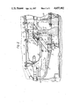
- FIG. 2 illustrates in greater detail part of the engine of FIG. 1 showing a part of the air cooling system for cooling a shaft of the engine;
- FIG. 3 illustrates a configuration of the static wall of the engine of FIG. 1;
- FIG. 4 illustrates an alternate configuration of the static wall of the engine of FIG. 1.
- a gas turbine aero engine 10 comprising a low pressure single stage compressor fan 11 mounted in a by-pass duct 12 and a core engine which comprises, in flow series, a multi stage high pressure axial flow compressor 13, a combustion chamber 14, a two stage high pressure turbine 15, a multi-stage low pressure turbine 16 and a jet pipe 50.
- the HP turbine 15 is connected to the HP compressor 13 by means of a shaft 17.
- the shaft 17 is supported at its rear end in a journal bearing 18 and the front end of the compressor 13 is mounted in a thrust bearing 19.
- the LP shaft 20 connecting the LP turbine 16 to the LP fan 11 passes through the bore of the HP shaft 17.
- the first stage disc of the HP turbine 15 has members 21 on its upstream side which co-operate with surfaces on an adjacent seal plate 22 to define air seals.
- the seal plate 22 is carried by a segmented inlet guide vane assembly 23 mounted in the turbine outer casing.
- the inner platform 25 of the guide vane assembly 23 supports the inner wall of an annular combustion chamber 14 (the outer wall of the combustion chamber 14 is carried by the combustion chamber outer casing 26).
- the inner platform 25 has two flanges projecting radially inwards.
- One flange 27 has attached to it a static wall structure 28 that serves to define a number of separate flow passageways through which cooling air can flow.
- combustion chamber inner casing 29 Bolted to the wall structure 28 is the combustion chamber inner casing 29. This casing encompasses the inner regions of the combustion chamber 14 and is supported at its upstream end by the outlet nozzle guide vane and diffuser assembly 30 of the HP compressor 13.
- the outer circumference of the seal plate 22 is provided with a recess into which the flange 31 on the inner platform 25 of the guide vane assembly 23 locates.
- the seal plate 22 has two recesses into each of which a thin wall webs 32,33 locates.
- the web 32,33 project forward from the plane of the plate 22 and are bolted to the wall structure 28 by the nuts and bolts 34.
- a cover plate 35 covers the upstream face of the first stage disc of the HP turbine.
- Some of the high pressure air supplied to the combustion chamber 14 is tapped from the downstream end of the HP compressor 13 and ducted along four separate flow paths.
- One flow path is around the outside of the outer wall of the combustion chamber 14 to issue through cooling holes in the leading edge of the guide vanes 36.
- a second flow path is around the outside of the inner wall of the combustion chamber 14 to issue from holes in the trailing edge of the vanes 36.
- the third flow is ducted between walls 28,29,32 and 33 to issue through nozzles 37 in the seal plate 22 and thereby cool the turbine blades in a similar manner to that described in U.S. Pat. No. 4,275,990, and is also used to cool the front face of the first stage disc of the HP turbine 15.
- the fourth flow is pre swirled by pre swirl nozzles 38 in the same direction as the direction of rotation of the compressor rotor 13.
- the swirling air flows between a static wall 39, which is bolted to the wall structure 28 and secured to the pre swirl nozzles 38, and the rotating shaft 17 to cool the shaft 17.
- a static wall 39 which is bolted to the wall structure 28 and secured to the pre swirl nozzles 38, and the rotating shaft 17 to cool the shaft 17.
- the air is then bled through large holes 40 into a diffusing passage 41 constituted by two spaced conical walls, which define an annular diffuser with a radially inward facing inlet and a radially outward facing outlet.
- a brush seal prevents the fourth flow of air by-passing the diffuser 41.
- the air discharged from the diffuser 41 passes through radial holes in the flange of web 33 between the bolts 34 and is discharged through nozzles 43 in seal plate 22, at a region between the air seals. Some of the air flows through passages in the rim of the first stage disc of the HP turbine 15 between the blade roots and issues from nozzles 44 at the downstream face of the first disc, and some is used to help cool the HP turbine blades. The air is then used to pressurise the disc rim seals 45 and 46.
- both the static wall 39 and the cover plate 35 are provided with openings 47,48 aligned to point in the same direction as the direction of swirl of the air flowing between the shaft 17 and the wall 39 (or between the first stage disc of the HP turbine 15 and the cover plate 35 as the case may be).
- Pressurised air on the side of the wall 39 (or the cover plate 35 as the case may be) remote from the swirling air flows through the openings 47 or 48 and energises the boundary layer adjacent the wall 39 (or cover plate 35) causing it to move in the same direction as the direction of swirl, thus reducing the viscous drag on the swirling air.
- the wall 39, or cover plate 35 may be pre-drilled with holes or slots defining the openings 47,48 or may be made from perforated, or foraminated metal sheets.
- the wall 39 or cover plate 35 may include air permeable panels (for example woven metal gauzes, or braiding or ceramic materials, as shown in FIGS. 3 and 4).
- the present invention may be employed elsewhere in the engine, for example, the static structure 49 adjacent the rear of the second stage HP turbine disc may be made air permeable and supplied on the side remote from the turbine disc with pressurised air.
- a similar effect to blowing air through static walls can be achieved in some applications by effectively reducing the pressure on the side of the wall remote from the swirling air to induce some of the swirling air to flow through openings in the wall thereby to induce flow of the boundary layer in the same direction as the direction of swirl.
- the openings 47,48 it is preferred to shape the openings 47,48 to direct the air flowing through them preferentially in the same direction as the direction of swirl. This may be achieved by punching the openings 47,48 to form shrouds or recesses that induce the air to flow in the desired direction. It is to be understood however, that it may not be essential to direct the air in this way. It may be sufficient to allow the air to flow or permeate through the wall in a direction which is generally normal to the wall and thereby effectively air-lubricate the wall to allow the boundary layer of air adjacent the wall to move in the same direction as the swirling air assisted by the air flow through the wall. This would be the case with air permeable panels such as those mentioned above.
Abstract
Description
Claims (3)
Applications Claiming Priority (2)
| Application Number | Priority Date | Filing Date | Title |
|---|---|---|---|
| GB8032873 | 1980-10-10 | ||
| GB08032873A GB2108202B (en) | 1980-10-10 | 1980-10-10 | Air cooling systems for gas turbine engines |
Publications (1)
| Publication Number | Publication Date |
|---|---|
| US4657482A true US4657482A (en) | 1987-04-14 |
Family
ID=10516606
Family Applications (1)
| Application Number | Title | Priority Date | Filing Date |
|---|---|---|---|
| US06/308,188 Expired - Lifetime US4657482A (en) | 1980-10-10 | 1981-09-18 | Air cooling systems for gas turbine engines |
Country Status (4)
| Country | Link |
|---|---|
| US (1) | US4657482A (en) |
| DE (1) | DE3138856C1 (en) |
| FR (1) | FR2520441B1 (en) |
| GB (1) | GB2108202B (en) |
Cited By (54)
| Publication number | Priority date | Publication date | Assignee | Title |
|---|---|---|---|---|
| US4719747A (en) * | 1984-08-04 | 1988-01-19 | MTU Motorern-und Turbinen-Union Munchen GmbH | Apparatus for optimizing the blade and sealing slots of a compressor of a gas turbine |
| US4759688A (en) * | 1986-12-16 | 1988-07-26 | Allied-Signal Inc. | Cooling flow side entry for cooled turbine blading |
| US4793772A (en) * | 1986-11-14 | 1988-12-27 | Mtu Motoren-Und Turbinen-Union Munchen Gmbh | Method and apparatus for cooling a high pressure compressor of a gas turbine engine |
| US4808073A (en) * | 1986-11-14 | 1989-02-28 | Mtu Motoren- Und Turbinen- Union Munchen Gmbh | Method and apparatus for cooling a high pressure compressor of a gas turbine engine |
| US4822244A (en) * | 1987-10-15 | 1989-04-18 | United Technologies Corporation | Tobi |
| US4882902A (en) * | 1986-04-30 | 1989-11-28 | General Electric Company | Turbine cooling air transferring apparatus |
| US4920741A (en) * | 1986-02-28 | 1990-05-01 | Mtu Motoren-Und Turbinen-Union Munchen Gmbh | Apparatus for venting the rotor structure of a compressor of a gas turbine power plant |
| US5189874A (en) * | 1990-03-23 | 1993-03-02 | Asea Brown Boveri Ltd. | Axial-flow gas turbine cooling arrangement |
| US5211003A (en) * | 1992-02-05 | 1993-05-18 | General Electric Company | Diffuser clean air bleed assembly |
| US5297386A (en) * | 1992-08-26 | 1994-03-29 | Societe Nationale D'etude Et De Construction De Moteurs D'aviation (S.N.E.C.M.A.) | Cooling system for a gas turbine engine compressor |
| US5498139A (en) * | 1994-11-09 | 1996-03-12 | United Technologies Corporation | Brush seal |
| US5555721A (en) * | 1994-09-28 | 1996-09-17 | General Electric Company | Gas turbine engine cooling supply circuit |
| EP0857856A2 (en) * | 1996-11-29 | 1998-08-12 | General Electric Company | Turbine rotor with an insulating coating at it's outer circumference |
| US5862666A (en) * | 1996-12-23 | 1999-01-26 | Pratt & Whitney Canada Inc. | Turbine engine having improved thrust bearing load control |
| US6035627A (en) * | 1998-04-21 | 2000-03-14 | Pratt & Whitney Canada Inc. | Turbine engine with cooled P3 air to impeller rear cavity |
| US6227801B1 (en) | 1999-04-27 | 2001-05-08 | Pratt & Whitney Canada Corp. | Turbine engine having improved high pressure turbine cooling |
| EP1186746A2 (en) * | 2000-09-06 | 2002-03-13 | Rolls-Royce Deutschland Ltd & Co KG | Swirl nozzle |
| US6468032B2 (en) | 2000-12-18 | 2002-10-22 | Pratt & Whitney Canada Corp. | Further cooling of pre-swirl flow entering cooled rotor aerofoils |
| US20030223893A1 (en) * | 2002-05-30 | 2003-12-04 | Snecma Moteurs | Cooling the upstream end plate of a high pressure turbine by means of a system of dual injectors at the end of the combustion chamber |
| EP1111189A3 (en) * | 1999-12-22 | 2004-01-07 | Rolls-Royce Deutschland GmbH | Cooling air path for the rotor of a gas turbine engine |
| US20060222486A1 (en) * | 2005-04-01 | 2006-10-05 | Maguire Alan R | Cooling system for a gas turbine engine |
| US20070116562A1 (en) * | 2005-11-18 | 2007-05-24 | General Electric Company | Methods and apparatus for cooling combustion turbine engine components |
| JP2008025579A (en) * | 2006-07-19 | 2008-02-07 | Snecma | Wall ventilating system for combustion chamber |
| US20100296926A1 (en) * | 2008-02-28 | 2010-11-25 | Mitsubishi Heavy Industries, Ltd. | Gas turbine and method for opening chamber of gas turbine |
| US20110129336A1 (en) * | 2008-05-29 | 2011-06-02 | Snecma | Assembly including a turbine disk for a gas turbine engine and a bearing-supporting journal, and cooling circuit for the turbine disk of such an assembly |
| US20120057967A1 (en) * | 2010-09-07 | 2012-03-08 | Laurello Vincent P | Gas turbine engine |
| WO2013152181A1 (en) | 2012-04-04 | 2013-10-10 | Geco Technology B.V. | Methods and devices for enhanced survey data collection |
| RU2514987C1 (en) * | 2013-03-04 | 2014-05-10 | Открытое акционерное общество "Авиадвигатель" | High-pressure turbine stator |
| US8935926B2 (en) | 2010-10-28 | 2015-01-20 | United Technologies Corporation | Centrifugal compressor with bleed flow splitter for a gas turbine engine |
| US8949030B2 (en) | 2011-07-29 | 2015-02-03 | Westerngeco L.L.C. | Attenuating sea-surface ghost wave effects in seismic data |
| JP2015045333A (en) * | 2013-08-27 | 2015-03-12 | ゼネラル・エレクトリック・カンパニイ | Inducer and diffuser configuration for gas turbine system |
| US9091172B2 (en) | 2010-12-28 | 2015-07-28 | Rolls-Royce Corporation | Rotor with cooling passage |
| US9103942B2 (en) | 2011-10-28 | 2015-08-11 | Westerngeco L.L.C. | Methods and systems for survey designs |
| US9228436B2 (en) | 2012-07-03 | 2016-01-05 | Solar Turbines Incorporated | Preswirler configured for improved sealing |
| US9274239B2 (en) | 2012-01-13 | 2016-03-01 | Westerngeco L.L.C. | Wavefield deghosting |
| US20160208713A1 (en) * | 2015-01-15 | 2016-07-21 | United Technologies Corporation | Gas turbine engine with high speed and temperature spool cooling system |
| US20160237903A1 (en) * | 2015-02-13 | 2016-08-18 | United Technologies Corporation | High Pressure Compressor Rotor Thermal Conditioning Using Conditioned Compressor Air |
| US20170037782A1 (en) * | 2015-01-20 | 2017-02-09 | United Technologies Corporation | Air mixing systems having mixing chambers for gas turbine engines |
| EP3133239A1 (en) * | 2015-08-19 | 2017-02-22 | United Technologies Corporation | Assembly for rotational equipment and corresponding aircraft propulsion system |
| US9594181B2 (en) | 2008-06-13 | 2017-03-14 | Westerngeco L.L.C. | Filtering and presentation of heading observations for coil shooting |
| US20170096939A1 (en) * | 2015-10-05 | 2017-04-06 | General Electric Company | Windage shield system and method of suppressing resonant acoustic noise |
| US9703000B2 (en) | 2008-05-15 | 2017-07-11 | Westerngeco L.L.C. | Multi-vessel coil shooting acquisition |
| EP3047110A4 (en) * | 2013-09-10 | 2017-07-19 | United Technologies Corporation | Flow splitting first vane support for gas turbine engine |
| EP3231994A1 (en) * | 2016-04-08 | 2017-10-18 | United Technologies Corporation | Compressor secondary flow aft cone cooling scheme |
| US9857491B2 (en) | 2008-05-15 | 2018-01-02 | Westerngeco L.L.C. | Multi-vessel coil shooting acquisition |
| US9869787B2 (en) | 2006-01-19 | 2018-01-16 | Westerngeco L.L.C. | Methods and systems for efficiently acquiring towed streamer seismic surveys |
| US10082589B2 (en) | 2008-06-13 | 2018-09-25 | Westerngeco L.L.C. | Method to determine the deviation of seismic equipment from a planned curved path |
| DE102019126128A1 (en) * | 2019-09-27 | 2021-04-01 | Rolls-Royce Deutschland Ltd & Co Kg | Gas turbine engine and method of cooling a rotor cone |
| US10967955B2 (en) * | 2017-10-09 | 2021-04-06 | Airbus Operations Gmbh | Vertical tail unit for flow control |
| US10975721B2 (en) | 2016-01-12 | 2021-04-13 | Pratt & Whitney Canada Corp. | Cooled containment case using internal plenum |
| US10974817B2 (en) * | 2017-10-09 | 2021-04-13 | Airbus Operations Gmbh | Vertical tail unit for flow control |
| FR3128971A1 (en) * | 2021-11-10 | 2023-05-12 | Safran Helicopter Engines | AIRCRAFT TURBOMACHINE AND RELATED METHOD |
| US11702981B1 (en) * | 2022-04-20 | 2023-07-18 | Raytheon Technologies Corporation | Turbine engine bleed waste heat recovery |
| US11821365B2 (en) | 2022-01-31 | 2023-11-21 | General Electric Company | Inducer seal with integrated inducer slots |
Families Citing this family (6)
| Publication number | Priority date | Publication date | Assignee | Title |
|---|---|---|---|---|
| DE3514352A1 (en) * | 1985-04-20 | 1986-10-23 | MTU Motoren- und Turbinen-Union München GmbH, 8000 München | GAS TURBINE ENGINE WITH DEVICES FOR DIVERSING COMPRESSOR AIR FOR COOLING HOT PARTS |
| US5187931A (en) * | 1989-10-16 | 1993-02-23 | General Electric Company | Combustor inner passage with forward bleed openings |
| US5127793A (en) * | 1990-05-31 | 1992-07-07 | General Electric Company | Turbine shroud clearance control assembly |
| US5759012A (en) * | 1996-12-13 | 1998-06-02 | Caterpillar Inc. | Turbine disc ingress prevention method and apparatus |
| GB9917957D0 (en) | 1999-07-31 | 1999-09-29 | Rolls Royce Plc | A combustor arrangement |
| FR3113925B1 (en) * | 2020-09-04 | 2022-12-02 | Safran Aircraft Engines | Improved aircraft turbine engine turbine cooling device |
Citations (22)
| Publication number | Priority date | Publication date | Assignee | Title |
|---|---|---|---|---|
| GB609028A (en) * | 1941-10-30 | 1948-09-24 | Rateau Soc | Improvements in or relating to cooling devices for the casings of gas turbine plant |
| GB621300A (en) * | 1946-02-22 | 1949-04-07 | Ltd Co Formerly Skoda Works | Arrangement for reducing the stress in gas turbine gas-cooled runner wheels |
| FR955159A (en) * | 1939-12-19 | 1950-01-10 | ||
| US2973937A (en) * | 1958-03-31 | 1961-03-07 | Gen Electric | Cooling structure |
| US3365172A (en) * | 1966-11-02 | 1968-01-23 | Gen Electric | Air cooled shroud seal |
| GB1157930A (en) * | 1966-12-28 | 1969-07-09 | Rolls Royce | Gas Turbine Jet Propulsion Engine |
| FR2030993A5 (en) * | 1969-08-18 | 1970-11-13 | Motoren Turbinen Union | |
| GB1217807A (en) * | 1969-07-19 | 1970-12-31 | Rolls Royce | Gas turbine engine |
| US3557553A (en) * | 1967-08-31 | 1971-01-26 | Daimler Benz Ag | Structural part of a gas turbine drive unit which is exposed to thermal load and is to be cooled by means of a gas |
| GB1270959A (en) * | 1968-09-27 | 1972-04-19 | Bennes Marrel | Means for cooling or regulating the temperature of a gas turbine engine |
| US3700418A (en) * | 1969-11-24 | 1972-10-24 | Gen Motors Corp | Cooled airfoil and method of making it |
| GB1387638A (en) * | 1971-02-09 | 1975-03-19 | Nissan Motor | Turbine blade cooling |
| US3893786A (en) * | 1973-06-07 | 1975-07-08 | Ford Motor Co | Air cooled shroud for a gas turbine engine |
| US4013376A (en) * | 1975-06-02 | 1977-03-22 | United Technologies Corporation | Coolable blade tip shroud |
| US4022542A (en) * | 1974-10-23 | 1977-05-10 | Teledyne Industries, Inc. | Turbine blade |
| US4126405A (en) * | 1976-12-16 | 1978-11-21 | General Electric Company | Turbine nozzle |
| US4151674A (en) * | 1976-06-14 | 1979-05-01 | Klahn Dale H | Flying cylinder |
| US4168348A (en) * | 1974-12-13 | 1979-09-18 | Rolls-Royce Limited | Perforated laminated material |
| GB2054046A (en) * | 1979-07-12 | 1981-02-11 | Rolls Royce | Cooling turbine rotors |
| US4273824A (en) * | 1979-05-11 | 1981-06-16 | United Technologies Corporation | Ceramic faced structures and methods for manufacture thereof |
| US4291531A (en) * | 1978-04-06 | 1981-09-29 | Rolls-Royce Limited | Gas turbine engine |
| US4434957A (en) * | 1982-03-30 | 1984-03-06 | Rolls-Royce Incorporated | Low drag surface |
-
1980
- 1980-10-10 GB GB08032873A patent/GB2108202B/en not_active Expired
-
1981
- 1981-09-18 US US06/308,188 patent/US4657482A/en not_active Expired - Lifetime
- 1981-09-30 DE DE3138856A patent/DE3138856C1/en not_active Expired
- 1981-10-09 FR FR8119083A patent/FR2520441B1/en not_active Expired
Patent Citations (22)
| Publication number | Priority date | Publication date | Assignee | Title |
|---|---|---|---|---|
| FR955159A (en) * | 1939-12-19 | 1950-01-10 | ||
| GB609028A (en) * | 1941-10-30 | 1948-09-24 | Rateau Soc | Improvements in or relating to cooling devices for the casings of gas turbine plant |
| GB621300A (en) * | 1946-02-22 | 1949-04-07 | Ltd Co Formerly Skoda Works | Arrangement for reducing the stress in gas turbine gas-cooled runner wheels |
| US2973937A (en) * | 1958-03-31 | 1961-03-07 | Gen Electric | Cooling structure |
| US3365172A (en) * | 1966-11-02 | 1968-01-23 | Gen Electric | Air cooled shroud seal |
| GB1157930A (en) * | 1966-12-28 | 1969-07-09 | Rolls Royce | Gas Turbine Jet Propulsion Engine |
| US3557553A (en) * | 1967-08-31 | 1971-01-26 | Daimler Benz Ag | Structural part of a gas turbine drive unit which is exposed to thermal load and is to be cooled by means of a gas |
| GB1270959A (en) * | 1968-09-27 | 1972-04-19 | Bennes Marrel | Means for cooling or regulating the temperature of a gas turbine engine |
| GB1217807A (en) * | 1969-07-19 | 1970-12-31 | Rolls Royce | Gas turbine engine |
| FR2030993A5 (en) * | 1969-08-18 | 1970-11-13 | Motoren Turbinen Union | |
| US3700418A (en) * | 1969-11-24 | 1972-10-24 | Gen Motors Corp | Cooled airfoil and method of making it |
| GB1387638A (en) * | 1971-02-09 | 1975-03-19 | Nissan Motor | Turbine blade cooling |
| US3893786A (en) * | 1973-06-07 | 1975-07-08 | Ford Motor Co | Air cooled shroud for a gas turbine engine |
| US4022542A (en) * | 1974-10-23 | 1977-05-10 | Teledyne Industries, Inc. | Turbine blade |
| US4168348A (en) * | 1974-12-13 | 1979-09-18 | Rolls-Royce Limited | Perforated laminated material |
| US4013376A (en) * | 1975-06-02 | 1977-03-22 | United Technologies Corporation | Coolable blade tip shroud |
| US4151674A (en) * | 1976-06-14 | 1979-05-01 | Klahn Dale H | Flying cylinder |
| US4126405A (en) * | 1976-12-16 | 1978-11-21 | General Electric Company | Turbine nozzle |
| US4291531A (en) * | 1978-04-06 | 1981-09-29 | Rolls-Royce Limited | Gas turbine engine |
| US4273824A (en) * | 1979-05-11 | 1981-06-16 | United Technologies Corporation | Ceramic faced structures and methods for manufacture thereof |
| GB2054046A (en) * | 1979-07-12 | 1981-02-11 | Rolls Royce | Cooling turbine rotors |
| US4434957A (en) * | 1982-03-30 | 1984-03-06 | Rolls-Royce Incorporated | Low drag surface |
Non-Patent Citations (1)
| Title |
|---|
| Esgar et al; Review of Status, Methods and Potentials of Gas Turbine Air Cooling, Research Publication NACA (1955). * |
Cited By (78)
| Publication number | Priority date | Publication date | Assignee | Title |
|---|---|---|---|---|
| US4719747A (en) * | 1984-08-04 | 1988-01-19 | MTU Motorern-und Turbinen-Union Munchen GmbH | Apparatus for optimizing the blade and sealing slots of a compressor of a gas turbine |
| US4920741A (en) * | 1986-02-28 | 1990-05-01 | Mtu Motoren-Und Turbinen-Union Munchen Gmbh | Apparatus for venting the rotor structure of a compressor of a gas turbine power plant |
| US4961309A (en) * | 1986-02-28 | 1990-10-09 | Mtu Motoren-Und Turbinen-Union Munchen Gmbh | Apparatus for venting the rotor structure of a compressor of a gas turbine power plant |
| US4882902A (en) * | 1986-04-30 | 1989-11-28 | General Electric Company | Turbine cooling air transferring apparatus |
| US4793772A (en) * | 1986-11-14 | 1988-12-27 | Mtu Motoren-Und Turbinen-Union Munchen Gmbh | Method and apparatus for cooling a high pressure compressor of a gas turbine engine |
| US4808073A (en) * | 1986-11-14 | 1989-02-28 | Mtu Motoren- Und Turbinen- Union Munchen Gmbh | Method and apparatus for cooling a high pressure compressor of a gas turbine engine |
| US4759688A (en) * | 1986-12-16 | 1988-07-26 | Allied-Signal Inc. | Cooling flow side entry for cooled turbine blading |
| US4822244A (en) * | 1987-10-15 | 1989-04-18 | United Technologies Corporation | Tobi |
| US5189874A (en) * | 1990-03-23 | 1993-03-02 | Asea Brown Boveri Ltd. | Axial-flow gas turbine cooling arrangement |
| GB2263945B (en) * | 1992-02-05 | 1995-06-07 | Gen Electric | Diffuser clean air bleed assembly |
| US5211003A (en) * | 1992-02-05 | 1993-05-18 | General Electric Company | Diffuser clean air bleed assembly |
| US5297386A (en) * | 1992-08-26 | 1994-03-29 | Societe Nationale D'etude Et De Construction De Moteurs D'aviation (S.N.E.C.M.A.) | Cooling system for a gas turbine engine compressor |
| US5555721A (en) * | 1994-09-28 | 1996-09-17 | General Electric Company | Gas turbine engine cooling supply circuit |
| US5498139A (en) * | 1994-11-09 | 1996-03-12 | United Technologies Corporation | Brush seal |
| EP0857856A2 (en) * | 1996-11-29 | 1998-08-12 | General Electric Company | Turbine rotor with an insulating coating at it's outer circumference |
| EP0857856A3 (en) * | 1996-11-29 | 2000-08-16 | General Electric Company | Turbine rotor with an insulating coating at it's outer circumference |
| US5862666A (en) * | 1996-12-23 | 1999-01-26 | Pratt & Whitney Canada Inc. | Turbine engine having improved thrust bearing load control |
| US6035627A (en) * | 1998-04-21 | 2000-03-14 | Pratt & Whitney Canada Inc. | Turbine engine with cooled P3 air to impeller rear cavity |
| US6227801B1 (en) | 1999-04-27 | 2001-05-08 | Pratt & Whitney Canada Corp. | Turbine engine having improved high pressure turbine cooling |
| EP1111189A3 (en) * | 1999-12-22 | 2004-01-07 | Rolls-Royce Deutschland GmbH | Cooling air path for the rotor of a gas turbine engine |
| EP1186746A2 (en) * | 2000-09-06 | 2002-03-13 | Rolls-Royce Deutschland Ltd & Co KG | Swirl nozzle |
| EP1186746A3 (en) * | 2000-09-06 | 2003-07-16 | Rolls-Royce Deutschland Ltd & Co KG | Swirl nozzle |
| US6468032B2 (en) | 2000-12-18 | 2002-10-22 | Pratt & Whitney Canada Corp. | Further cooling of pre-swirl flow entering cooled rotor aerofoils |
| US6787947B2 (en) * | 2002-05-30 | 2004-09-07 | Snecma Moteurs | Cooling the upstream end plate of a high pressure turbine by means of a system of dual injectors at the end of the combustion chamber |
| US20030223893A1 (en) * | 2002-05-30 | 2003-12-04 | Snecma Moteurs | Cooling the upstream end plate of a high pressure turbine by means of a system of dual injectors at the end of the combustion chamber |
| US7625171B2 (en) | 2005-04-01 | 2009-12-01 | Rolls-Royce Plc | Cooling system for a gas turbine engine |
| US20060222486A1 (en) * | 2005-04-01 | 2006-10-05 | Maguire Alan R | Cooling system for a gas turbine engine |
| GB2426289A (en) * | 2005-04-01 | 2006-11-22 | Rolls Royce Plc | Gas turbine engine cooling system |
| GB2426289B (en) * | 2005-04-01 | 2007-07-04 | Rolls Royce Plc | Cooling system for a gas turbine engine |
| US20070116562A1 (en) * | 2005-11-18 | 2007-05-24 | General Electric Company | Methods and apparatus for cooling combustion turbine engine components |
| US7303372B2 (en) * | 2005-11-18 | 2007-12-04 | General Electric Company | Methods and apparatus for cooling combustion turbine engine components |
| US9869787B2 (en) | 2006-01-19 | 2018-01-16 | Westerngeco L.L.C. | Methods and systems for efficiently acquiring towed streamer seismic surveys |
| JP2008025579A (en) * | 2006-07-19 | 2008-02-07 | Snecma | Wall ventilating system for combustion chamber |
| US20100296926A1 (en) * | 2008-02-28 | 2010-11-25 | Mitsubishi Heavy Industries, Ltd. | Gas turbine and method for opening chamber of gas turbine |
| US8568094B2 (en) * | 2008-02-28 | 2013-10-29 | Mitsubishi Heavy Industries, Ltd. | Gas turbine and method for opening chamber of gas turbine |
| US9857491B2 (en) | 2008-05-15 | 2018-01-02 | Westerngeco L.L.C. | Multi-vessel coil shooting acquisition |
| US9766359B2 (en) | 2008-05-15 | 2017-09-19 | Westerngeco L.L.C. | Multi-vessel coil shooting acquisition |
| US9703000B2 (en) | 2008-05-15 | 2017-07-11 | Westerngeco L.L.C. | Multi-vessel coil shooting acquisition |
| US20110129336A1 (en) * | 2008-05-29 | 2011-06-02 | Snecma | Assembly including a turbine disk for a gas turbine engine and a bearing-supporting journal, and cooling circuit for the turbine disk of such an assembly |
| US8899913B2 (en) * | 2008-05-29 | 2014-12-02 | Snecma | Assembly including a turbine disk for a gas turbine engine and a bearing-supporting journal, and cooling circuit for the turbine disk of such an assembly |
| US10082589B2 (en) | 2008-06-13 | 2018-09-25 | Westerngeco L.L.C. | Method to determine the deviation of seismic equipment from a planned curved path |
| US9594181B2 (en) | 2008-06-13 | 2017-03-14 | Westerngeco L.L.C. | Filtering and presentation of heading observations for coil shooting |
| US8727703B2 (en) * | 2010-09-07 | 2014-05-20 | Siemens Energy, Inc. | Gas turbine engine |
| US20120057967A1 (en) * | 2010-09-07 | 2012-03-08 | Laurello Vincent P | Gas turbine engine |
| US8935926B2 (en) | 2010-10-28 | 2015-01-20 | United Technologies Corporation | Centrifugal compressor with bleed flow splitter for a gas turbine engine |
| US9091172B2 (en) | 2010-12-28 | 2015-07-28 | Rolls-Royce Corporation | Rotor with cooling passage |
| US8949030B2 (en) | 2011-07-29 | 2015-02-03 | Westerngeco L.L.C. | Attenuating sea-surface ghost wave effects in seismic data |
| US9103942B2 (en) | 2011-10-28 | 2015-08-11 | Westerngeco L.L.C. | Methods and systems for survey designs |
| US9274239B2 (en) | 2012-01-13 | 2016-03-01 | Westerngeco L.L.C. | Wavefield deghosting |
| WO2013152181A1 (en) | 2012-04-04 | 2013-10-10 | Geco Technology B.V. | Methods and devices for enhanced survey data collection |
| US9228436B2 (en) | 2012-07-03 | 2016-01-05 | Solar Turbines Incorporated | Preswirler configured for improved sealing |
| RU2514987C1 (en) * | 2013-03-04 | 2014-05-10 | Открытое акционерное общество "Авиадвигатель" | High-pressure turbine stator |
| CN104420997A (en) * | 2013-08-27 | 2015-03-18 | 通用电气公司 | Inducer and diffuser configuration for a gas turbine system |
| JP2015045333A (en) * | 2013-08-27 | 2015-03-12 | ゼネラル・エレクトリック・カンパニイ | Inducer and diffuser configuration for gas turbine system |
| US10190425B2 (en) | 2013-09-10 | 2019-01-29 | United Technologies Corporation | Flow splitting first vane support for gas turbine engine |
| EP3047110A4 (en) * | 2013-09-10 | 2017-07-19 | United Technologies Corporation | Flow splitting first vane support for gas turbine engine |
| US20160208713A1 (en) * | 2015-01-15 | 2016-07-21 | United Technologies Corporation | Gas turbine engine with high speed and temperature spool cooling system |
| US9677475B2 (en) * | 2015-01-15 | 2017-06-13 | United Technologies Corporation | Gas turbine engine with high speed and temperature spool cooling system |
| US20170037782A1 (en) * | 2015-01-20 | 2017-02-09 | United Technologies Corporation | Air mixing systems having mixing chambers for gas turbine engines |
| US10415478B2 (en) * | 2015-01-20 | 2019-09-17 | United Technologies Corporation | Air mixing systems having mixing chambers for gas turbine engines |
| US20160237903A1 (en) * | 2015-02-13 | 2016-08-18 | United Technologies Corporation | High Pressure Compressor Rotor Thermal Conditioning Using Conditioned Compressor Air |
| EP3133239A1 (en) * | 2015-08-19 | 2017-02-22 | United Technologies Corporation | Assembly for rotational equipment and corresponding aircraft propulsion system |
| US20170051751A1 (en) * | 2015-08-19 | 2017-02-23 | United Technologies Corporation | Seal assembly for rotational equipment |
| CN106939836A (en) * | 2015-10-05 | 2017-07-11 | 通用电气公司 | Windage cover system and the method for suppressing resonance noise |
| EP3153658A1 (en) * | 2015-10-05 | 2017-04-12 | General Electric Company | Windage shield system |
| US20170096939A1 (en) * | 2015-10-05 | 2017-04-06 | General Electric Company | Windage shield system and method of suppressing resonant acoustic noise |
| CN106939836B (en) * | 2015-10-05 | 2019-04-16 | 通用电气公司 | Windage cover system for gas-turbine unit |
| US10352245B2 (en) * | 2015-10-05 | 2019-07-16 | General Electric Company | Windage shield system and method of suppressing resonant acoustic noise |
| US10975721B2 (en) | 2016-01-12 | 2021-04-13 | Pratt & Whitney Canada Corp. | Cooled containment case using internal plenum |
| EP3231994A1 (en) * | 2016-04-08 | 2017-10-18 | United Technologies Corporation | Compressor secondary flow aft cone cooling scheme |
| US10967955B2 (en) * | 2017-10-09 | 2021-04-06 | Airbus Operations Gmbh | Vertical tail unit for flow control |
| US10974817B2 (en) * | 2017-10-09 | 2021-04-13 | Airbus Operations Gmbh | Vertical tail unit for flow control |
| US20210214072A1 (en) * | 2017-10-09 | 2021-07-15 | Airbus Operations Gmbh | Vertical tail unit for flow control |
| US11565795B2 (en) * | 2017-10-09 | 2023-01-31 | Airbus Operations Gmbh | Vertical tail unit for flow control |
| DE102019126128A1 (en) * | 2019-09-27 | 2021-04-01 | Rolls-Royce Deutschland Ltd & Co Kg | Gas turbine engine and method of cooling a rotor cone |
| FR3128971A1 (en) * | 2021-11-10 | 2023-05-12 | Safran Helicopter Engines | AIRCRAFT TURBOMACHINE AND RELATED METHOD |
| US11821365B2 (en) | 2022-01-31 | 2023-11-21 | General Electric Company | Inducer seal with integrated inducer slots |
| US11702981B1 (en) * | 2022-04-20 | 2023-07-18 | Raytheon Technologies Corporation | Turbine engine bleed waste heat recovery |
Also Published As
| Publication number | Publication date |
|---|---|
| FR2520441B1 (en) | 1988-01-22 |
| DE3138856C1 (en) | 1983-11-17 |
| GB2108202A (en) | 1983-05-11 |
| FR2520441A1 (en) | 1983-07-29 |
| GB2108202B (en) | 1984-05-10 |
Similar Documents
| Publication | Publication Date | Title |
|---|---|---|
| US4657482A (en) | Air cooling systems for gas turbine engines | |
| US4920741A (en) | Apparatus for venting the rotor structure of a compressor of a gas turbine power plant | |
| US5555721A (en) | Gas turbine engine cooling supply circuit | |
| JP5279400B2 (en) | Turbomachine diffuser | |
| US2988325A (en) | Rotary fluid machine with means supplying fluid to rotor blade passages | |
| US6564555B2 (en) | Apparatus for forming a combustion mixture in a gas turbine engine | |
| US3963368A (en) | Turbine cooling | |
| US4425079A (en) | Air sealing for turbomachines | |
| US4822244A (en) | Tobi | |
| US4141672A (en) | Dual or multistream turbine | |
| US4291531A (en) | Gas turbine engine | |
| US4796429A (en) | Combustor diffuser | |
| US3437313A (en) | Gas turbine blade cooling | |
| US8894360B2 (en) | Turbomachine compressor rotor including centripetal air bleed means | |
| US20040120803A1 (en) | Turbine shroud segment apparatus for reusing cooling air | |
| US2658338A (en) | Gas turbine housing | |
| US20040258517A1 (en) | Hot gas path assembly | |
| US5941687A (en) | Gas turbine engine turbine system | |
| US10683758B2 (en) | Inter-stage cooling for a turbomachine | |
| US4272955A (en) | Diffusing means | |
| US3614257A (en) | Gas turbine engine | |
| JPS6183403A (en) | Apparatus for automatically controlling play gap of labyrinth packing of turbine engine | |
| US10422244B2 (en) | System for cooling a turbine shroud | |
| US6840737B2 (en) | Gas turbine cooling system | |
| GB2057573A (en) | Turbine rotor assembly |
Legal Events
| Date | Code | Title | Description |
|---|---|---|---|
| AS | Assignment |
Owner name: ROLLS-ROYCE LIMITED, 65 BUCKINGHAM GATE, LONDON SW Free format text: ASSIGNMENT OF ASSIGNORS INTEREST.;ASSIGNOR:NEAL, PETER F.;REEL/FRAME:003931/0423 Effective date: 19810828 |
|
| AS | Assignment |
Owner name: ROLLS-ROYCE PLC Free format text: CHANGE OF NAME;ASSIGNOR:ROLLS-ROYCE (1971) LIMITED;REEL/FRAME:004555/0363 Effective date: 19860501 |
|
| FEPP | Fee payment procedure |
Free format text: PAYOR NUMBER ASSIGNED (ORIGINAL EVENT CODE: ASPN); ENTITY STATUS OF PATENT OWNER: LARGE ENTITY |
|
| STCF | Information on status: patent grant |
Free format text: PATENTED CASE |
|
| FPAY | Fee payment |
Year of fee payment: 4 |
|
| FPAY | Fee payment |
Year of fee payment: 8 |
|
| FPAY | Fee payment |
Year of fee payment: 12 |