US2656146A - Turbine blade construction - Google Patents
Turbine blade construction Download PDFInfo
- Publication number
- US2656146A US2656146A US19743A US1974348A US2656146A US 2656146 A US2656146 A US 2656146A US 19743 A US19743 A US 19743A US 1974348 A US1974348 A US 1974348A US 2656146 A US2656146 A US 2656146A
- Authority
- US
- United States
- Prior art keywords
- blade
- shank
- strip
- rotor
- deck
- Prior art date
- Legal status (The legal status is an assumption and is not a legal conclusion. Google has not performed a legal analysis and makes no representation as to the accuracy of the status listed.)
- Expired - Lifetime
Links
Images


Classifications
-
- F—MECHANICAL ENGINEERING; LIGHTING; HEATING; WEAPONS; BLASTING
- F01—MACHINES OR ENGINES IN GENERAL; ENGINE PLANTS IN GENERAL; STEAM ENGINES
- F01D—NON-POSITIVE DISPLACEMENT MACHINES OR ENGINES, e.g. STEAM TURBINES
- F01D5/00—Blades; Blade-carrying members; Heating, heat-insulating, cooling or antivibration means on the blades or the members
- F01D5/12—Blades
- F01D5/14—Form or construction
- F01D5/18—Hollow blades, i.e. blades with cooling or heating channels or cavities; Heating, heat-insulating or cooling means on blades
- F01D5/187—Convection cooling
-
- B—PERFORMING OPERATIONS; TRANSPORTING
- B21—MECHANICAL METAL-WORKING WITHOUT ESSENTIALLY REMOVING MATERIAL; PUNCHING METAL
- B21D—WORKING OR PROCESSING OF SHEET METAL OR METAL TUBES, RODS OR PROFILES WITHOUT ESSENTIALLY REMOVING MATERIAL; PUNCHING METAL
- B21D53/00—Making other particular articles
- B21D53/78—Making other particular articles propeller blades; turbine blades
-
- F—MECHANICAL ENGINEERING; LIGHTING; HEATING; WEAPONS; BLASTING
- F01—MACHINES OR ENGINES IN GENERAL; ENGINE PLANTS IN GENERAL; STEAM ENGINES
- F01D—NON-POSITIVE DISPLACEMENT MACHINES OR ENGINES, e.g. STEAM TURBINES
- F01D5/00—Blades; Blade-carrying members; Heating, heat-insulating, cooling or antivibration means on the blades or the members
- F01D5/12—Blades
- F01D5/14—Form or construction
- F01D5/147—Construction, i.e. structural features, e.g. of weight-saving hollow blades
-
- F—MECHANICAL ENGINEERING; LIGHTING; HEATING; WEAPONS; BLASTING
- F01—MACHINES OR ENGINES IN GENERAL; ENGINE PLANTS IN GENERAL; STEAM ENGINES
- F01D—NON-POSITIVE DISPLACEMENT MACHINES OR ENGINES, e.g. STEAM TURBINES
- F01D5/00—Blades; Blade-carrying members; Heating, heat-insulating, cooling or antivibration means on the blades or the members
- F01D5/12—Blades
- F01D5/14—Form or construction
- F01D5/18—Hollow blades, i.e. blades with cooling or heating channels or cavities; Heating, heat-insulating or cooling means on blades
- F01D5/187—Convection cooling
- F01D5/188—Convection cooling with an insert in the blade cavity to guide the cooling fluid, e.g. forming a separation wall
- F01D5/189—Convection cooling with an insert in the blade cavity to guide the cooling fluid, e.g. forming a separation wall the insert having a tubular cross-section, e.g. airfoil shape
-
- F—MECHANICAL ENGINEERING; LIGHTING; HEATING; WEAPONS; BLASTING
- F01—MACHINES OR ENGINES IN GENERAL; ENGINE PLANTS IN GENERAL; STEAM ENGINES
- F01D—NON-POSITIVE DISPLACEMENT MACHINES OR ENGINES, e.g. STEAM TURBINES
- F01D5/00—Blades; Blade-carrying members; Heating, heat-insulating, cooling or antivibration means on the blades or the members
- F01D5/30—Fixing blades to rotors; Blade roots ; Blade spacers
- F01D5/3007—Fixing blades to rotors; Blade roots ; Blade spacers of axial insertion type
-
- Y—GENERAL TAGGING OF NEW TECHNOLOGICAL DEVELOPMENTS; GENERAL TAGGING OF CROSS-SECTIONAL TECHNOLOGIES SPANNING OVER SEVERAL SECTIONS OF THE IPC; TECHNICAL SUBJECTS COVERED BY FORMER USPC CROSS-REFERENCE ART COLLECTIONS [XRACs] AND DIGESTS
- Y10—TECHNICAL SUBJECTS COVERED BY FORMER USPC
- Y10T—TECHNICAL SUBJECTS COVERED BY FORMER US CLASSIFICATION
- Y10T29/00—Metal working
- Y10T29/49—Method of mechanical manufacture
- Y10T29/49316—Impeller making
- Y10T29/4932—Turbomachine making
- Y10T29/49321—Assembling individual fluid flow interacting members, e.g., blades, vanes, buckets, on rotary support member
-
- Y—GENERAL TAGGING OF NEW TECHNOLOGICAL DEVELOPMENTS; GENERAL TAGGING OF CROSS-SECTIONAL TECHNOLOGIES SPANNING OVER SEVERAL SECTIONS OF THE IPC; TECHNICAL SUBJECTS COVERED BY FORMER USPC CROSS-REFERENCE ART COLLECTIONS [XRACs] AND DIGESTS
- Y10—TECHNICAL SUBJECTS COVERED BY FORMER USPC
- Y10T—TECHNICAL SUBJECTS COVERED BY FORMER US CLASSIFICATION
- Y10T29/00—Metal working
- Y10T29/49—Method of mechanical manufacture
- Y10T29/49826—Assembling or joining
- Y10T29/49908—Joining by deforming
- Y10T29/49915—Overedge assembling of seated part
-
- Y—GENERAL TAGGING OF NEW TECHNOLOGICAL DEVELOPMENTS; GENERAL TAGGING OF CROSS-SECTIONAL TECHNOLOGIES SPANNING OVER SEVERAL SECTIONS OF THE IPC; TECHNICAL SUBJECTS COVERED BY FORMER USPC CROSS-REFERENCE ART COLLECTIONS [XRACs] AND DIGESTS
- Y10—TECHNICAL SUBJECTS COVERED BY FORMER USPC
- Y10T—TECHNICAL SUBJECTS COVERED BY FORMER US CLASSIFICATION
- Y10T29/00—Metal working
- Y10T29/49—Method of mechanical manufacture
- Y10T29/49826—Assembling or joining
- Y10T29/49908—Joining by deforming
- Y10T29/49938—Radially expanding part in cavity, aperture, or hollow body
-
- Y—GENERAL TAGGING OF NEW TECHNOLOGICAL DEVELOPMENTS; GENERAL TAGGING OF CROSS-SECTIONAL TECHNOLOGIES SPANNING OVER SEVERAL SECTIONS OF THE IPC; TECHNICAL SUBJECTS COVERED BY FORMER USPC CROSS-REFERENCE ART COLLECTIONS [XRACs] AND DIGESTS
- Y10—TECHNICAL SUBJECTS COVERED BY FORMER USPC
- Y10T—TECHNICAL SUBJECTS COVERED BY FORMER US CLASSIFICATION
- Y10T29/00—Metal working
- Y10T29/49—Method of mechanical manufacture
- Y10T29/49826—Assembling or joining
- Y10T29/49947—Assembling or joining by applying separate fastener
- Y10T29/49959—Nonresilient fastener
Definitions
- This invention relates. to rotor blades for turbines, compressors, blowers or the like, and to a. method of; making such blades. Morepartioularly, the inventionv is: directed toa novel sheetmetal hollowbladejand to amethod of making said blades.
- the blade.v construction herein disclosed is designed for use as a turbine rotor-blade. Obviously, however, the invention is also applicable to blades for compressors, blow,- ers and like devices.
- An object of this invention comprises the provision of ablade construction andv a method of fabrieatin same er by the ma an h f p r of each blade are made separately and then assembled together. This. procedure permits the construction; oi a strong and economical blade,
- the invention comprises a hollow sheet metal blade made in two parts, a blade shelf part and ablade main part, both said parts being formed of. sheet metal material.
- the shelf part ofthe blade is provided with a split shank to permit spreading of the sides of said shank, .50 that the working portion oi the blade main partmay be inserted between said sides and through, a, hole in the deck ofv the shelf: part, said hole being shaped tocorrespond to the-profile of the ad acent working portion of the blade when said two parts are assembled,
- each blade main part is made from an elongate strip of sheet-likematerial by form;- ing each end of said strip to the profile and shape, of one face of. the desired blade, and iol d-.
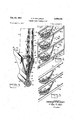
- Figure 1 is, an explodedv perspective view, 11- lustrating a. portion of a turbine, rotor with a turbine rotor blade embodying, the invention, said. figure also. illustrating the. method of. se curing said blade to said rotor;
- Figure 2 is, an exploded perspective view 11+ lustrating themain and shelf parts of a blade andthe method of assembling said blade parts;
- Fi ure 3 is a nerepe t veview, p rtly in. sea hi o e Q mpleted b de ass mb y;
- Figure 7 is a perspective view of an elongate i lf i s ee e ia $3 and termed Q tha ai t can h fie ed abou a .c lihdri l Pin 1111 0. em membe for dish si ih ith n a turbine roto bla e,
- Fi ure 9 is a perspective view of an elongate str p of hee m tal. mate ial rom whi h the m n p Q1 il lade 1 lfilfidi 33 material being Q and ma h hed t the rimer ize;
- Fi ures 9 sa are seciiehel vie are; ee n 9 and H-.-!' qf isure 9 ht? 2 is. a. Pe spectiv vi w' e m terial of F re 9 ii r each. h lf 9f. s i m t ia a been formed to th r th Or o e face f the made;
- Figure 16 is a perspective view illustrating, h si s-h -side le iqhi e wo alv s of t shank of he l de he i art; a d
- FIG 17 is a sectional View illustrating a hamle s? sh lf ar 9? a b ad Reier ihs fi st te sh es an 2 th drawing
- a blade i6 embodying the invention comprises a shelf part l2 and a main part 14 adapted to be assembled together and secured in key-holelike slots l6 in a turbine rotor is.
- the slots l6 extend across the periphery of said rotor 16 in a direction inclined to the axis of said rotor such that said slots are substantiallv parallel to a line joining the leading and trailing ed es 20 and 22 respectively at the inner end of the working portion 21.; of the blade l6.
- said slots I6 may be otherwise inclined, for example they may be disposed parallel to the axis of the rotor l8.
- each blade shelf part l2 of each blade i6 is formed as hereinafter described and comprises a deck 26 with a pair of spaced arms 28 and 30 extending from said deck to form the side walls of a split shank construction for said shelf part.
- each deck 26 has a width and a shape such that it substantially abuts the decks 26 of the adiacent blades to form a continuous inner annular boundary for the fiuid with which the blades [6 react.
- each deck 26 is provided with a hole 32 throu h which the working portion 24 of its associated blade main part M is inserted as hereinafter described.
- the shank arms or side walls 28 and 3b of each shelf part l2 converge to a reduced.
- each blade shelf part has a hollow ke'y-hole-like profile and said profile is such as to fit the keyhole-like slots [6 in the rotor l8.
- the blade main part M of each blade i6 is formed as hereinafter described.
- Said main part I4 comprises an elon ate strip of metal in which the two ends of said strip comprise the faces or workin portion 24 of the blade and an intermediate length of said strip, between said ends, forms the shank 36 of said main part l4.
- the shank 36 of its main part 14 also has a keyis inserted between said side walls or arms and,
- each blade main part [4 has a reduced width section 38 and termimates in a hollow cylindrical or tubular end portion 46.
- the tubular end portion 46 of each blade main part It is adapted to be co-axially fitted between the semi-tubular ends 34 of the arms 28 and 36 of its shelf part M with the reduced width section 36 of said main blade part l4 fitted between the reduced widthportion 33 of said arms 28 and 30.
- each blade main part 14 of a turbine blade I6 is hollow and may have an opening 42 in the leading edge of its shank 36 for the admission of a suitable cooling medium into said turbine blade 10.
- the shelf and main parts of a blade [0 are assembled as indicated in Fi ure 2.
- the shank side walls or arms 28 and 30 of the blade shelf part I2 are spread apart, as indicated by the arrows 44 and 46, and the blade main part 14 as indicated by the arrow 46, said main part M is inserted through the hole 32 in the deck 26, until its tubular end 46 is received between the semi-tubular ends 34 of the blade shelf part 12.
- the profile of the hole 32 is such that when a blade 16 is thus assembled, the walls of said hole snugly fit about the adjacent portion of its blade main part Ht.
- each blade Ill progressively changes slightly from its deck 26 to its outer or tip end, as is conventional in turbine blades, the cross-section of said working portion progressively decreases from its deck 26 to its tip end, thereby permitting insertion of a blade main part !4 through the hole 62 in its deck 26.
- each blade Ill is similarly constructed, assembled, and secured to the rotor l8. For simplicity, however, only one blade I6 is illustrated in Figure 1.
- each said part tends to dampen resonant vibrations which may tend to occur in the other of said parts.
- the blade parts i2 and M of each blade 10 may be brazed, welded, or otherwise secured together along their abutting surfaces.
- a suitable cooling medium may be introduced into the turbine blades through the openings 42 in their blade shanks.
- a bafiie member 52 is preferably disposed within each blade.
- said baflie member is not illustrated in Figures 1 and 2 although it would be visible through the opening 52 in the shank of the blade.
- the bafiie members 52 have a profile similar to but smaller than the internal profile of the blade main parts it in order to leave a space therebetween for flow of the cooling medium radially outwardly through each blade.
- each of the bave members 52 has a shank portion 54 with a tubular end disposed around the pin 50.
- dimples 56 are formed in the baiiie members to keep them spaced from the internal walls of the working portions 24 of their blades.
- bafiie members 52 do not have openings corresponding to the openings 42 in the shanks of their respective blades, whereby, when a cooling medium is introduced into the blades 16, through said shank openings 42, each baffie member 52 confines said medium to flow through its blade along the space between said baflle member and the adjacent internal Wall of the working portion 24 of its blade. In this way the bafiie members 52 provideintimate contact between said cooling medium and the walls of the blades l6.
- Said cooling medium may discharge from the open tip or outer ends of the blades l0 into the fluid with which said blades react or the tips of all the rotor blades I0 secured to the rotor l3 may be connected together by a ring into which said cooling medium discharges.
- each blade Iii between the shank ends: of its baffle member 52 The function of each spreader member 53 is to keep the two faces of its associated baflie member from collapsing against each other under the action of the centrifugal forces acting thereon during rotor rotation.
- Each spreader member 58 is. secured in position within its bavette memberfor example by spot welding thereto or in any other suitable manner.
- the spreader members 58 are also of sheet metal construction and the outer surface of said membersis fluted as indicated at 6!! to provide said member with sufficient strength, and rigidity to keep apart the faces of the baffle member 52..
- the battle membersfiz are each formed from an elongate strip of sheet-like material 62, as illustrated in Figures '7 and 8.
- the two end halves of said elongate strip are out andformed by suitable dies to a profile similar to but somewhat smaller than the internal profile of one of the faces of a blade main part Hi.
- said strip 52 is provided with the dimples 55 previously mentioned.
- a cylindrical pin lid is disposed across the middle of the strip 62 transverse to the long dimension of said strip.
- said strip is folded about said pin so as to wrap a small central length of said strip 62 approximately 360 about said pin with the two ends of said strip extending laterally from said pin and with the longitudinal edges of each end of said strip disposed adjacent to the corresponding longitudinal edges of the other end of said strip, thereby forming a baffle member 52.
- a spreader member 53 is disposed adjacent the pin 6t so that, upon folding said strip, said spreader member is disposed in position between the sides of the shank end 54 of the resulting bafile member 52.
- the longitudinal edges of one. end of the strip 62 are preferably folded over the.
- each blade main part 14 is formed from an elongate strip of sheet-like material H1 in a manner imil r to the method of forming the baffle members 52.
- the strip in is flat except its longitudinal edges 12 and I l are slightly tapered on one side as illustrated in Figures 10 and 11 respectively. This tapered edge construction facilitates the subsequent formation of the relatively thin trailing edge of'each blade ID.
- the reason for the ogee curved edge portions 16 at the center of the two longitudinal edges of the strip In is hereinafter explained.
- the two ends of the elongate strip in are each new formed by suitable dies to the profile and shape of one of the faces of a blade main part- Hl.
- the resulting strip is indicated at '58 in Figure 12.
- the elongate strip '58 is then folded about a baflie member 52 and a pin 6d (assembled as in FigureB) with said pin disposed across the centerof said elongate strip and disposed transverse to the long dimension of said strip.
- This folding of a strip 18 issimilartothe previously described folding 0.1. a battle.- member strip 62 about a pin 64 except; a. completed baffle, member 52 is disposed between said pin 64 and said strip 18.
- a small central length of a strip 18 is wrapped approximately 360 about said pin 64 with the two ends of said strip extending laterally from said pin and-with. the longitudinal edges of each end of said strip being disposed adjacent to the corresponding longitudinal edges of the other end of said strip.
- This latter folding operation forms a hollow blade main part id with a baiiie member 59. disposed therein.
- a small length of an adjacent pair of said longitudinal edges are spaced apart to form, the opening 42 in the shank of said blade part.
- the remainder of said longitudinal edges of the two ends of the strip it! are then welded or otherwise secured together to form the leading and trailing edges of a blade main part Hi, the welds at the leading and trailing edges of a blade Hi being indicated at it and 8b in Figure 4.
- the pins 52 used for anchoring the blades Ill-to the rotor l8, have a slightly larger diameter than the pinata in order to provide a tight fit between each blade and the walls of the rotor slot 16.
- the pins 164 are removed before each blade main part Id and its shelf part ii. are secured to the rotor l8, as described in connection with Figures 1 and 2.
- the size of the rotor slots It may be such that each. blade It, with its pin fi l may be tightly driven into a rotor slot IS.
- a blade main part M with its internal baffle construction is best illustrated in FiguresB and 13.
- the ogee curved edge portions 75 at the center of the two longitudinal edges of a strip 10, are provided in order that the end faces of its subsequently formed tubular shank end 38 are parallel to the plane of the rotor disc [8 when said tubular shank end is disposed in a slot 15 in saidyrotor, said slots being inclined to the rotor axis.
- the slots l5 are formed parallel to the rotor axis, the ogee curved edges 16 would be replaced by straight edges parallel to the long dimension of the strip Hi.
- FIGs 14 to 17 inclusive illustrate a method of forming the shelf parts it of the blades 10.
- the deck 26 of each blade shelf part is formed from a flat piece of sheet-like material 8! cut to the shape illustrated in Figure 14.
- the edge portions 82, 84, 86, and 88 of said flat sheet 8B are then folded along the dot-and-dash lines 99 to form a. downturned flange around a deck 26.
- the hole 32 is cut in the deck 26 to permit: insertion of the blade main part therethrough as hereinbefore described.
- the shank of each. blade shelf part l2 has a split construction and comprises the two side walls 28 and 30. As illustrated in Figure 16 each side wall 28 and 30 isseparately formed from sheet metal stampings.
- the shank side Walls 28 and 30 of a blade shelf part 12 are illustrated, in
- each blade shelf part i2 has a deck 26 and a split shank comprising side walls 28 and 39.
- each shelf part can r adily be formed from a single piece of sheet-like material instead of from the three pieces illustrated in Figures 14 and 15. With the construction illustrated, however, the junction between the side walls 28 and 3t and the deck flanges 82 and 8% increases the rigidity of said deck.
- a rotor for compressors, turbines, blowers or the like said rotor having a rim with a plurality of circumferentially spaced slots, each said slot extending at least part way across the periphery of said rotor rim and having a relatively wide portion radially inwardly of the rotor periphery; a plurality of blades each secured in one of said slots and extending radially outwardly therefrom, each of said blades comprising a shelf part and a main part, each blade shelf part having a deck and a split shank extending inwardly from said deck and terminating in facing semitubular portions, the sides of said split shank being fitted between the sides of one of said slots, each blade main part having its working portion projecting through the deck of its associated shelf part and having a shank disposed between the sides of the shank of its associated shelf part, the shank of each blade main part terminating in a tubular portion disposed between the facing semi-tubular portions of its associated sheh" part; and a
- a hollow blade as described in claim 2 in which the shank of said blade main part has an opening for the admission of a heat exchange medium therein; and a hollow baffle member disposed within said main part for confining said medium to flow over the interior surface of the working portion of said blade, said baflie memher having a profile generally similar to that of said main blade part and comprising a single strip of material with the intermediate portion of said strip forming a tubular end of said bafiie member concentrically disposed within the tubular end of said main blade part.
- the method of making a rotor blade for turbines, compressors, blowers or the like comp-rising the steps of forming a blade shelf part with a deck having a hole therethrough' and a of spaced arms extending from said deck; forming a blade main part with a working portion and a shank; and inserting the working portion of said main part between said arms and through said deck hole only so far as to leave the shank of said main part between the sides of said split shank.
- a hollow rotor blade for turbines, compressors, blowers, or the like comprising a main part and a shelf part; said shelf part having a deck with a pair of spaced arms extending from said deck and terminating in facing semi-tubular end portions; said main blade part comprising a working portion and a shank with said shank being disposed between said arms and having an end portion disposed between said semi-tubular end portions and with said Working portion projecting through an opening in said deck, said main blade'part working portion being hollow and said main blade par-t shank having an Opening providing communication between the outside of the blade and the interior of said hollow working portion.
Description
Filed April 8. 19.48
F. P. 'SOLLINGER TURBINE BLADE CONSTRUCTION 4 Shets-Sheet 1 ATTORNEY F. P. SOLLINGER TURBINE BLADE CONSTRUCTION 4 Sheets-Sheet 2 Opt. 20, 1953 Filed April 8, 194a INVENTOR FERDINAND F. SDLLINEER ATTORNEY Oct. 20, 1953 F. P. ISOLLINGER 2,656,146 I TURBINE BLADE CONSTRUCTION i Filed April, e, 1948 4 Sheets-Sheet 5 1 g Y FznomAuu ef affinsm. #5 BY A'ITORNEY Oct. 20, 1953 F. P. SOLLINGER 6,
TURBINE BLADE CONSTRUCTION Filed April 8, 1948 4 Sheets-Sheet 4 INVENTOR FERDINAND F. SEILLINEER ATTORNEY Patented Oct. 20, 1953 TURBINE BI'iADE CONSTRUCTION Ferdinandll Sollinger, Paterson, N J., assignor to Qurtiss-Wriglit Corporation, a corporation of Delaware Application April 8, 1948, SerialNo. 19,74; 19.; q a lhsi. 01. 2.53. -3 3- .2'
This invention relates. to rotor blades for turbines, compressors, blowers or the like, and to a. method of; making such blades. Morepartioularly, the inventionv is: directed toa novel sheetmetal hollowbladejand to amethod of making said blades. The blade.v construction herein disclosed is designed for use as a turbine rotor-blade. Obviously, however, the invention is also applicable to blades for compressors, blow,- ers and like devices.
The blades of turbines are commonly pro.- vided with a shelf portion abutting the shelf portions Of. adjacent blades to, define an air-.- nular boundary for theturbine motivefluid. An object of this invention comprises the provision of ablade construction andv a method of fabrieatin same er by the ma an h f p r of each blade are made separately and then assembled together. This. procedure permits the construction; oi a strong and economical blade,
It is also common practice to make turbine blades. hollow for reducing the weight of the blades and for permitting the flow of a cooling medium through the, blades: furtherobject offthis invention resides in the provision of a novel method of making a hollow blade and in thestructure Of. the blade per se.
Specifically the invention comprises a hollow sheet metal blade made in two parts, a blade shelf part and ablade main part, both said parts being formed of. sheet metal material. The shelf part ofthe blade is provided with a split shank to permit spreading of the sides of said shank, .50 that the working portion oi the blade main partmay be inserted between said sides and through, a, hole in the deck ofv the shelf: part, said hole being shaped tocorrespond to the-profile of the ad acent working portion of the blade when said two parts are assembled, In addition, each blade main part is made from an elongate strip of sheet-likematerial by form;- ing each end of said strip to the profile and shape, of one face of. the desired blade, and iol d-. ing said strip about an axis disposed across the center of. said strip and disposed transverse to the lone di ension of sa st p Sh a to ing the longitudinal edges ofone end of said strip adjacent the longitudinal edgesof the other end of: said strip. Said adjacent edges are then secured together, as by welding, to form the lead: ing and trailing. edges of the blade This construction permits easy control of the grain flow lines in the blade material thereby permitting the construction of a. blade which is both strong and li ht in eightreierah y, t hank po tio o each blad is f med. o as to ve a external key-hole-like profilethereby permitting said blade. to; be. secured in a. keyhole-like slot f rme n t p ri h f a tu bine re o Other objects of the invention W ll become apparent upon readingthe annexed detailed. description inv connection With the drawing in which:. t
Figure 1 is, an explodedv perspective view, 11- lustrating a. portion of a turbine, rotor with a turbine rotor blade embodying, the invention, said. figure also. illustrating the. method of. se curing said blade to said rotor;
Figure 2 is, an exploded perspective view 11+ lustrating themain and shelf parts of a blade andthe method of assembling said blade parts;
Fi ure 3 is a nerepe t veview, p rtly in. sea hi o e Q mpleted b de ass mb y;
Fi ures it and are. sectional v ews p c: ively tak n alon l ne 4 4. and 5:5. of Fi ur s end. and also lliist atm t e adjacent blades;
Figure s a t fi fifil fi ie 9 h. fi dmem e for se i q hh hh with an interna heme memb r. on oll n he flow o a h a exchange medium through a blade;
Figure 7 is a perspective view of an elongate i lf i s ee e e ia $3 and termed Q tha ai t can h fie ed abou a .c lihdri l Pin 1111 0. em membe for dish si ih ith n a turbine roto bla e,
e 8 i a pe pecti view, partl se iQ- a heme me b r wi it s re d r m mber disposed therein;
Fi ure 9 is a perspective view of an elongate str p of hee m tal. mate ial rom whi h the m n p Q1 il lade 1 lfilfidi 33 material being Q and ma h hed t the rimer ize;
Fi ures 9 sa are seciiehel vie are; ee n 9 and H-.-!' qf isure 9 ht? 2 is. a. Pe spectiv vi w' e m terial of F re 9 ii r each. h lf 9f. s i m t ia a been formed to th r th Or o e face f the made;
ll- 3 ,5 fi fi l i w. pa t .9- qn l u tra in e tem late ihhih Pa iii a blade;
E lfi 1 is Q 1% W 9 1 et metal m ial mm w i h he he 9 t el P of '91? lhq Pan 1? the fr m Figure 15 is a perspective view oi the deck of a blade shelf part;
Figure 16 is a perspective view illustrating, h si s-h -side le iqhi e wo alv s of t shank of he l de he i art; a d
Figure 17 is a sectional View illustrating a hamle s? sh lf ar 9? a b ad Reier ihs fi st te sh es an 2 th drawing, a blade i6 embodying the invention comprises a shelf part l2 and a main part 14 adapted to be assembled together and secured in key-holelike slots l6 in a turbine rotor is. Preferably and as illustrated, the slots l6 extend across the periphery of said rotor 16 in a direction inclined to the axis of said rotor such that said slots are substantiallv parallel to a line joining the leading and trailing ed es 20 and 22 respectively at the inner end of the working portion 21.; of the blade l6. Obviously, however. said slots I6 may be otherwise inclined, for example they may be disposed parallel to the axis of the rotor l8.
By workin portion 24 of a blade 16 is meant that portion of said blade which reacts with the fluid. For example, in the case of a compressor or blower, the working portions of their blades act against the fluid while, in the case of a turblue, the working portions of the blades are acted against by said fluid.
The blade shelf part l2 of each blade i6 is formed as hereinafter described and comprises a deck 26 with a pair of spaced arms 28 and 30 extending from said deck to form the side walls of a split shank construction for said shelf part. As best seen in Figure 4, each deck 26 has a width and a shape such that it substantially abuts the decks 26 of the adiacent blades to form a continuous inner annular boundary for the fiuid with which the blades [6 react. In addition, each deck 26 is provided with a hole 32 throu h which the working portion 24 of its associated blade main part M is inserted as hereinafter described. The shank arms or side walls 28 and 3b of each shelf part l2 converge to a reduced. width portion 33 adjacent its shank end and each arm or side wall terminates in a hollow semi-cylindrical portion 34 facing a corresponding semi-cylindrical portion 34 on the end of the other arm or side wall. Accordingly, the split shank end of each blade shelf part has a hollow ke'y-hole-like profile and said profile is such as to fit the keyhole-like slots [6 in the rotor l8.
The blade main part M of each blade i6 is formed as hereinafter described. Said main part I4 comprises an elon ate strip of metal in which the two ends of said strip comprise the faces or workin portion 24 of the blade and an intermediate length of said strip, between said ends, forms the shank 36 of said main part l4. Like the split shank of the shelf part of each blade Hi, the shank 36 of its main part 14 also has a keyis inserted between said side walls or arms and,
hole-like profile and said profile is adapted to fit within the internal kev-hole-like profile formed by thefacing sides of the ends of the arms 28 and 36. Thus, the shank 36 of each blade main part [4 has a reduced width section 38 and termimates in a hollow cylindrical or tubular end portion 46. The tubular end portion 46 of each blade main part It is adapted to be co-axially fitted between the semi-tubular ends 34 of the arms 28 and 36 of its shelf part M with the reduced width section 36 of said main blade part l4 fitted between the reduced widthportion 33 of said arms 28 and 30. In addition, and as illustrated, each blade main part 14 of a turbine blade I6 is hollow and may have an opening 42 in the leading edge of its shank 36 for the admission of a suitable cooling medium into said turbine blade 10.
The shelf and main parts of a blade [0 are assembled as indicated in Fi ure 2. Thus the shank side walls or arms 28 and 30 of the blade shelf part I2 are spread apart, as indicated by the arrows 44 and 46, and the blade main part 14 as indicated by the arrow 46, said main part M is inserted through the hole 32 in the deck 26, until its tubular end 46 is received between the semi-tubular ends 34 of the blade shelf part 12. The profile of the hole 32 is such that when a blade 16 is thus assembled, the walls of said hole snugly fit about the adjacent portion of its blade main part Ht. Although the pitch of the working portion 24 of each blade Ill progressively changes slightly from its deck 26 to its outer or tip end, as is conventional in turbine blades, the cross-section of said working portion progressively decreases from its deck 26 to its tip end, thereby permitting insertion of a blade main part !4 through the hole 62 in its deck 26.
After assembly of the shelf and main parts to form a completed blade W, said blade is mounted on the rotor is by insertion of its composite shank end into a key-hole-like slot !6 in the rotor l8 and then a pin 50 is driven into the tubular end as to securely anchor the blade in position on the rotor l8. Each blade Ill is similarly constructed, assembled, and secured to the rotor l8. For simplicity, however, only one blade I6 is illustrated in Figure 1.
With the shank ends of the two parts I2 and Hi of each blade I!) secured and held together in a rotor slot 16, each said part tends to dampen resonant vibrations which may tend to occur in the other of said parts. If desired, the blade parts i2 and M of each blade 10 may be brazed, welded, or otherwise secured together along their abutting surfaces.
As previously mentioned, a suitable cooling medium may be introduced into the turbine blades through the openings 42 in their blade shanks. To facilitate cooling of the blades, a bafiie member 52 is preferably disposed within each blade. For reasons of clarity, said baflie member is not illustrated in Figures 1 and 2 although it would be visible through the opening 52 in the shank of the blade.
Referring now to Figures 3 to 6 inclusive, the bafiie members 52 have a profile similar to but smaller than the internal profile of the blade main parts it in order to leave a space therebetween for flow of the cooling medium radially outwardly through each blade. Like the blade main part It, each of the baiile members 52 has a shank portion 54 with a tubular end disposed around the pin 50. In addition, dimples 56 are formed in the baiiie members to keep them spaced from the internal walls of the working portions 24 of their blades. Also, the bafiie members 52 do not have openings corresponding to the openings 42 in the shanks of their respective blades, whereby, when a cooling medium is introduced into the blades 16, through said shank openings 42, each baffie member 52 confines said medium to flow through its blade along the space between said baflle member and the adjacent internal Wall of the working portion 24 of its blade. In this way the bafiie members 52 provideintimate contact between said cooling medium and the walls of the blades l6. Said cooling medium may discharge from the open tip or outer ends of the blades l0 into the fluid with which said blades react or the tips of all the rotor blades I0 secured to the rotor l3 may be connected together by a ring into which said cooling medium discharges.
If the blades in are used as air compressor blades instead of turbine blades, it may be desirable to pass a heating medium, instead of a cooling medium, through at least some of the blades in order; to .preyent formation. of ice there- In addition to the balile members 52,. aspreader member 58. may be disposed within each blade Iii between the shank ends: of its baffle member 52. The function of each spreader member 53 is to keep the two faces of its associated baflie member from collapsing against each other under the action of the centrifugal forces acting thereon during rotor rotation. Each spreader member 58 is. secured in position within its baiile memberfor example by spot welding thereto or in any other suitable manner. Preferably the spreader members 58 are also of sheet metal construction and the outer surface of said membersis fluted as indicated at 6!! to provide said member with sufficient strength, and rigidity to keep apart the faces of the baffle member 52..
The battle membersfiz are each formed from an elongate strip of sheet-like material 62, as illustrated in Figures '7 and 8. The two end halves of said elongate strip are out andformed by suitable dies to a profile similar to but somewhat smaller than the internal profile of one of the faces of a blade main part Hi. In addition, said strip 52 is provided with the dimples 55 previously mentioned.
Then, a cylindrical pin lid is disposed across the middle of the strip 62 transverse to the long dimension of said strip. Thereupon, said strip is folded about said pin so as to wrap a small central length of said strip 62 approximately 360 about said pin with the two ends of said strip extending laterally from said pin and with the longitudinal edges of each end of said strip disposed adjacent to the corresponding longitudinal edges of the other end of said strip, thereby forming a baffle member 52. Prior to said folding operation, a spreader member 53 is disposed adjacent the pin 6t so that, upon folding said strip, said spreader member is disposed in position between the sides of the shank end 54 of the resulting bafile member 52. Also, the longitudinal edges of one. end of the strip 62 are preferably folded over the. longitudinal edges of its other half, as indicated at 65 and I5! in Figure 8. The engaged longitudinal, edges at. B5 and til are preferably only frietionally clamped together so that relative sliding movements of said engaged edges, in response to vibration of its blade, tend to dampen said vibration. In addition, the spreader member 58. may be spot Welded into position as indicated at 68, Figure 8. and. as previously mentioned.
As illustrated in Figures 9 to 13, each blade main part 14 is formed from an elongate strip of sheet-like material H1 in a manner imil r to the method of forming the baffle members 52. In Figure 9, the strip in is flat except its longitudinal edges 12 and I l are slightly tapered on one side as illustrated in Figures 10 and 11 respectively. This tapered edge construction facilitates the subsequent formation of the relatively thin trailing edge of'each blade ID. The reason for the ogee curved edge portions 16 at the center of the two longitudinal edges of the strip In is hereinafter explained.
The two ends of the elongate strip in are each new formed by suitable dies to the profile and shape of one of the faces of a blade main part- Hl. The resulting strip is indicated at '58 in Figure 12. The elongate strip '58 is then folded about a baflie member 52 and a pin 6d (assembled as in FigureB) with said pin disposed across the centerof said elongate strip and disposed transverse to the long dimension of said strip. This folding of a strip 18 issimilartothe previously described folding 0.1. a battle.- member strip 62 about a pin 64 except; a. completed baffle, member 52 is disposed between said pin 64 and said strip 18. Thus, a small central length of a strip 18 is wrapped approximately 360 about said pin 64 with the two ends of said strip extending laterally from said pin and-with. the longitudinal edges of each end of said strip being disposed adjacent to the corresponding longitudinal edges of the other end of said strip. This latter folding operation forms a hollow blade main part id with a baiiie member 59. disposed therein. A small length of an adjacent pair of said longitudinal edges are spaced apart to form, the opening 42 in the shank of said blade part. The remainder of said longitudinal edges of the two ends of the strip it! are then welded or otherwise secured together to form the leading and trailing edges of a blade main part Hi, the welds at the leading and trailing edges of a blade Hi being indicated at it and 8b in Figure 4.
The pins 52, used for anchoring the blades Ill-to the rotor l8, have a slightly larger diameter than the pinata in order to provide a tight fit between each blade and the walls of the rotor slot 16. With this construction, the pins 164 are removed before each blade main part Id and its shelf part ii. are secured to the rotor l8, as described in connection with Figures 1 and 2. Alternatively, however, the size of the rotor slots It; may be such that each. blade It, with its pin fi l may be tightly driven into a rotor slot IS. A blade main part M with its internal baffle construction is best illustrated in FiguresB and 13.
The ogee curved edge portions 75, at the center of the two longitudinal edges of a strip 10, are provided in order that the end faces of its subsequently formed tubular shank end 38 are parallel to the plane of the rotor disc [8 when said tubular shank end is disposed in a slot 15 in saidyrotor, said slots being inclined to the rotor axis. Obviously, however, if the slots l5 are formed parallel to the rotor axis, the ogee curved edges 16 would be replaced by straight edges parallel to the long dimension of the strip Hi.
At this. point it should be noted that instead of forming each end of an elongate strip iii, to
the profile and shape of one face of a blade main part l4, prior to the folding operation about a pin 64, said forming operation may be performed after at least part of said folding operation..
Figures 14 to 17 inclusive, illustrate a method of forming the shelf parts it of the blades 10. The deck 26 of each blade shelf part is formed from a flat piece of sheet-like material 8! cut to the shape illustrated in Figure 14. The edge portions 82, 84, 86, and 88 of said flat sheet 8B are then folded along the dot-and-dash lines 99 to form a. downturned flange around a deck 26. In addition, the hole 32 is cut in the deck 26 to permit: insertion of the blade main part therethrough as hereinbefore described. The shank of each. blade shelf part l2 has a split construction and comprises the two side walls 28 and 30. As illustrated in Figure 16 each side wall 28 and 30 isseparately formed from sheet metal stampings. The shank side Walls 28 and 30 of a blade shelf part 12 are illustrated, in
the exploded view of Figure 16, prior to their assembly with a deck 26. The ends of the side walls 28 and 39, remote from their semi-tubular ends 34,, are secured to the flanges 82 and 86, respectively, of their deck 26, for example by welding. With this construction, each blade shelf part i2 has a deck 26 and a split shank comprising side walls 28 and 39.
Preferably the hole 32 in the deck 2% of each blade is formed with an inturn flange 92, as illustrated in Figure 17. With this flange construction, the centrifugal forces acting on each deck 26, during rotor rotation, tend to cause said flange 92 to grip tightly the adjacent portion of its associated blade main part it. This flange construction has not been illustrated in Figure 3.
Since the side walls 28 and 3t of each blade shelf part i2 constitute continuations of the deck flanges $2 and 86 of said shelf part, each shelf part can r adily be formed from a single piece of sheet-like material instead of from the three pieces illustrated in Figures 14 and 15. With the construction illustrated, however, the junction between the side walls 28 and 3t and the deck flanges 82 and 8% increases the rigidity of said deck.
While I have described my invention in detail in its present preferred embodiment, it will be obvious to those skilled in the art, after understanding my invention, that various changes and modifications may be made therein without departing from the spirit or scope thereof. I aim in the appended claims to cover all such modifications.
I claim as my invention:
1. A rotor for compressors, turbines, blowers or the like: said rotor having a rim with a plurality of circumferentially spaced slots, each said slot extending at least part way across the periphery of said rotor rim and having a relatively wide portion radially inwardly of the rotor periphery; a plurality of blades each secured in one of said slots and extending radially outwardly therefrom, each of said blades comprising a shelf part and a main part, each blade shelf part having a deck and a split shank extending inwardly from said deck and terminating in facing semitubular portions, the sides of said split shank being fitted between the sides of one of said slots, each blade main part having its working portion projecting through the deck of its associated shelf part and having a shank disposed between the sides of the shank of its associated shelf part, the shank of each blade main part terminating in a tubular portion disposed between the facing semi-tubular portions of its associated sheh" part; and a pin tightly fitted within the tubular portion the shank of each blade main part.
2. A hollow blade for the rotor of a turbine, compressor, blower or the like in which said rotor has a slot extending at least part way across the rotor periphery and said slot has a relatively wide portion radially inwardly of the rotor periphery: said blade comprising a main part and a shelf part; said shelf part having a deck with a pair of spaced arms extending from said deck and terminating in facing semi-tubular portions adapted to be received within said rotor slot; said main part comprising a single elongate strip of material in which the two faces of the working portion of said blade are formed by the two ends of said strip and the shank of said main part includes a tubular end formed by a length of said strip inter-mediate said two ends; said main and shelf parts being arranged with the working porion of said main part extending through the deck of said shelf part and with the shank of said main part disposed between said arms so that said tubular end is disposed between said semi-tubular portions.
3. A hollow blade as described in claim 2 in which the shank of said blade main part has an opening for the admission of a heat exchange medium therein.
4. A hollow blade as described in claim 2 in which the shank of said blade main part has an opening for the admission of a heat exchange medium therein; and a hollow baffle member disposed within said main part for confining said medium to flow over the interior surface of the working portion of said blade, said baflie memher having a profile generally similar to that of said main blade part and comprising a single strip of material with the intermediate portion of said strip forming a tubular end of said bafiie member concentrically disposed within the tubular end of said main blade part.
5. The method of making a rotor blade for turbines, compressors, blowers or the like: said method comp-rising the steps of forming a blade shelf part with a deck having a hole therethrough' and a of spaced arms extending from said deck; forming a blade main part with a working portion and a shank; and inserting the working portion of said main part between said arms and through said deck hole only so far as to leave the shank of said main part between the sides of said split shank.
6. The method making and securing a blade for a compressor, turbine, blower or the like, to a rotor having a slot across its periphery with said slot having an enlarged cylindrical portion radially inwardly of the rotor periphery: said method comprising the steps of forming a blade shelf part with a deck having a hole therethrough and with a pair of spaced shank arms extending from said deck and having facing semi-cy1indrical shank ends; forming a main blade part with a working portion and a shank portion having a hollow cylindrical end of enlarged width relative to the adjacent part of said shank; insorting the working portion of said main blade part between said arms and through said deck hole so as to leave the hollow cylindrical shank end of said main blade part embraced by said semi-cylindrical shank ends; inserting the shank ends of said main and shelf blade parts into said rotor slot with said hollow cylindrical end and the embracing semi-cylindrical ends received within the enlarged cylindrical portion of said slot; and then driving a cylindrical pin into said hollow cylindrical shank end of the main blade part.
7. The method of making and securing a blade for a compressor, turbine, blower or the like, to a rotor having a slot across its periphery with said slot having an enlarged width tubular portion radially inwardly of the rotor periphery; said method comprising the steps of forming a blade shelf part with a deck having a hole therethrough and with a pair of spaced shank arms extending from said deck and having facing semi-tubular shank ends; forming a main blade part with a working portion and a shank portion having a hollow tubular end of enlarged width relative to the adjacent part of said shank portion; assemblying the main and shelf blade parts with the shank portion of the main blade part disposed between the shank arms of the shelf blade part so that said semi-tubular ends of the shelf blade part embrace the hollow tubular shank end of the main blade part and with the working portion of said main blade part projecting through said deck hole; inserting the shank ends of said main and shelf blade parts into said rotor slot with said hollow tubular end and the embracing sem tubular ends received within the enlarged width portion of said slot; and then driving a pin into said hollow tubular shank end of the main blade part.
8. A hollow rotor blade for turbines, compressors, blowers, or the like; said blade comprising a main part and a shelf part; said shelf part having a deck with a pair of spaced arms extending from said deck and terminating in facing semi-tubular end portions; said main blade part comprising a working portion and a shank with said shank being disposed between said arms and having an end portion disposed between said semi-tubular end portions and with said Working portion projecting through an opening in said deck, said main blade'part working portion being hollow and said main blade par-t shank having an Opening providing communication between the outside of the blade and the interior of said hollow working portion.
9. A blade for the rotor of a turbine, compressor, blower or the like in which said rotor has a slot extending at least part way across the rotor periphery and said slot has a relatively Wide portion radially inwardly of the rotor periphery: said blade comprising a main part and a shelf part; said shelf part having a deck with a pair of spaced arms extending from said deck and terminating in facing semi-tubular portions adapted to be received within said rotor slot; said main part having a working portion and a shank terminating in a tubular portion; said main and shelf parts being arranged with the blade working portion of said main part projecting through said deck and with the shank of said main part disposed between said arms so that said tubular portion is disposed between said facing semi-tubular portions.
10. The method of making a rotor blade for turbines, compressors or the like: said method comprising the steps of forming a blade shelf part with a deck having a hole therethrough and with a pair of arms extending from said deck and having facing semi-tubular ends; forming a hollow blade main part with a working portion and a shank having a tubular end; and inserting the working portion of said main part between 10 said arms and through said deck hole only so far as to leave the tubular shank end of said main part between the semi-tubular ends of said arms; said hollow blade main part being made by the steps of forming an elongate stri of sheet-like material so that each end portion of said strip has a profile corresponding to one face of said blade such that when viewed from one side one end of said strip is mainly concave and the other end of the strip is mainly convex, folding said strip about an axis disposed across an intermediate length of said strip and disposed transverse to the long dimension of said strip so as to portion with the two ends of said strip extending laterally from the same side of said tubular portion whereby the shank of said blade main part has an external key-hole-like profile, said folding operation being sufficient to bring at least the major portion of the longitudinal edges of one end of said strip adjacent to the longitudinal edges of the other end of said strip, and securing said adjacent longitudinal edges together to form the leading and trailing edges of the working portion of said blade.
FERDINAND P. SOLLIN GER.
References Cited in the file of this patent UNITED STATES PATENTS Number Name Date 389,180 Wiggins Sept. 4, 1888 754,984 Fagerstrom Mar. 22, 1904 926,442 Smoot June 29, 1909 1,035,364 Le Blanc Aug. 13, 1912 1,516,607 Johanson Nov. 25, 1924 1,596,114 Murray Aug. 17, 1926 1,880,454 Klocke Oct. 4, 1932 2,013,622 Bedford et al. Sept. 3, 1935 2,040,640 Bedford et al. May 12, 1936 2,322,290 Gabel June 22, 1943 2,333 997 Glans Nov. 9, 1943 2,347,034 Doran Apr. 18, 1944 FOREIGN PATENTS Number Country Date 6,640 Great Britain 1907 31,520 France Dec. 2, 1926 166,859 Great Britain July 28, 1921 891,635 France Dec. 11, 1943
Priority Applications (1)
| Application Number | Priority Date | Filing Date | Title |
|---|---|---|---|
| US19743A US2656146A (en) | 1948-04-08 | 1948-04-08 | Turbine blade construction |
Applications Claiming Priority (1)
| Application Number | Priority Date | Filing Date | Title |
|---|---|---|---|
| US19743A US2656146A (en) | 1948-04-08 | 1948-04-08 | Turbine blade construction |
Publications (1)
| Publication Number | Publication Date |
|---|---|
| US2656146A true US2656146A (en) | 1953-10-20 |
Family
ID=21794794
Family Applications (1)
| Application Number | Title | Priority Date | Filing Date |
|---|---|---|---|
| US19743A Expired - Lifetime US2656146A (en) | 1948-04-08 | 1948-04-08 | Turbine blade construction |
Country Status (1)
| Country | Link |
|---|---|
| US (1) | US2656146A (en) |
Cited By (60)
| Publication number | Priority date | Publication date | Assignee | Title |
|---|---|---|---|---|
| US2762114A (en) * | 1951-08-28 | 1956-09-11 | Gen Motors Corp | Method of making sheet metal turbine bucket |
| US2801073A (en) * | 1952-06-30 | 1957-07-30 | United Aircraft Corp | Hollow sheet metal blade or vane construction |
| US2819870A (en) * | 1955-04-18 | 1958-01-14 | Oleh A Wayne | Sheet metal blade base |
| US2819869A (en) * | 1950-05-02 | 1958-01-14 | Jr Andre J Meyer | Mounting arrangement for turbine or compressor blading |
| US2830357A (en) * | 1955-05-27 | 1958-04-15 | Bristol Aero Engines Ltd | Blades for gas turbines |
| US2836391A (en) * | 1951-10-10 | 1958-05-27 | Gen Motors Corp | Turbine bucket with cast-in insert |
| US2850793A (en) * | 1953-03-20 | 1958-09-09 | Gen Motors Corp | Method of making refrigerating apparatus |
| US2853272A (en) * | 1952-09-12 | 1958-09-23 | Napier & Son Ltd | Hollow blades for turbo machines |
| US2859011A (en) * | 1953-07-27 | 1958-11-04 | Gen Motors Corp | Turbine bucket and liner |
| US2861775A (en) * | 1953-06-04 | 1958-11-25 | Power Jets Res & Dev Ltd | Tubular blades |
| US2865598A (en) * | 1954-03-03 | 1958-12-23 | Merland L Moseson | Air cooled turbine wheel design |
| US2873088A (en) * | 1953-05-21 | 1959-02-10 | Gen Electric | Lightweight rotor construction |
| US2873944A (en) * | 1952-09-10 | 1959-02-17 | Gen Motors Corp | Turbine blade cooling |
| US2875948A (en) * | 1953-01-19 | 1959-03-03 | Stalker Dev Company | Thin wall bladed wheels for axial flow machines |
| US2887957A (en) * | 1953-05-29 | 1959-05-26 | Stalker Corp | Bladed axial flow pump construction |
| US2896907A (en) * | 1955-09-28 | 1959-07-28 | John C Freche | Air-cooled blade |
| US2906495A (en) * | 1955-04-29 | 1959-09-29 | Eugene F Schum | Turbine blade with corrugated strut |
| US2912222A (en) * | 1952-08-02 | 1959-11-10 | Gen Electric | Turbomachine blading and method of manufacture thereof |
| US2916808A (en) * | 1955-03-28 | 1959-12-15 | Gen Electric | Method of making a blade for turbomachines |
| US2925250A (en) * | 1952-05-30 | 1960-02-16 | Power Jets Res & Dev Ltd | Blades for compressors, turbines and the like |
| US2933238A (en) * | 1954-06-24 | 1960-04-19 | Edward A Stalker | Axial flow compressors incorporating boundary layer control |
| US2940726A (en) * | 1955-11-08 | 1960-06-14 | Napier & Son Ltd | Hollow blades for turbines and the like |
| US2947066A (en) * | 1957-05-08 | 1960-08-02 | Tumavicus Julius William | Method of blade construction |
| US2950598A (en) * | 1954-11-22 | 1960-08-30 | Otto R Nemeth | Air cooled gas turbine power plant |
| US2954208A (en) * | 1953-01-09 | 1960-09-27 | Gen Motors Corp | Air foil section |
| US2978168A (en) * | 1954-12-06 | 1961-04-04 | Relle Royce Ltd | Bladed rotor for axial-flow fluid machine |
| US2978796A (en) * | 1958-04-07 | 1961-04-11 | Westinghouse Electric Corp | Method of securing using an explosive charge |
| US3027138A (en) * | 1951-12-10 | 1962-03-27 | Power Jets Res & Dev Ltd | Turbine blades |
| US3073568A (en) * | 1958-06-27 | 1963-01-15 | Edward A Stalker | Composite blades for turbines, compressors and the like |
| US3202343A (en) * | 1962-05-16 | 1965-08-24 | Desalination Plants | Compressor arrangement |
| US3255514A (en) * | 1962-05-16 | 1966-06-14 | Desalination Plants | Method of fabricating rotor assemblies |
| US3291446A (en) * | 1965-04-13 | 1966-12-13 | Chrysler Corp | Turbine wheel |
| US3333818A (en) * | 1965-03-22 | 1967-08-01 | Gen Motors Corp | Turbine rotor-jet nozzle assembly |
| US3365124A (en) * | 1966-02-21 | 1968-01-23 | Gen Electric | Compressor structure |
| US3572970A (en) * | 1969-01-23 | 1971-03-30 | Gen Electric | Turbomachinery blade spacer |
| US3776523A (en) * | 1972-04-27 | 1973-12-04 | Universal Fence Inc | Structural tube assembly |
| US3801222A (en) * | 1972-02-28 | 1974-04-02 | United Aircraft Corp | Platform for compressor or fan blade |
| US4037990A (en) * | 1976-06-01 | 1977-07-26 | General Electric Company | Composite turbomachinery rotor |
| US4489468A (en) * | 1982-06-24 | 1984-12-25 | Elliott Turbomachinery Co., Inc. | Method of providing a multivalve turbine nozzle ring interface seal |
| US4595340A (en) * | 1984-07-30 | 1986-06-17 | General Electric Company | Gas turbine bladed disk assembly |
| US5022825A (en) * | 1988-10-07 | 1991-06-11 | United Technologies Corporation | Pitch retention member |
| US5022824A (en) * | 1988-10-07 | 1991-06-11 | United Technologies Corporation | Pinned airfoil propeller blade |
| US5030063A (en) * | 1990-02-08 | 1991-07-09 | General Motors Corporation | Turbomachine rotor |
| US5102300A (en) * | 1988-10-07 | 1992-04-07 | United Technologies Corporation | Pinned airfoil propeller assembly |
| EP0541207A1 (en) * | 1991-11-04 | 1993-05-12 | General Electric Company | Impingement cooled airfoil with bonding foil insert |
| US5259730A (en) * | 1991-11-04 | 1993-11-09 | General Electric Company | Impingement cooled airfoil with bonding foil insert |
| US5277548A (en) * | 1991-12-31 | 1994-01-11 | United Technologies Corporation | Non-integral rotor blade platform |
| US5836800A (en) * | 1997-04-03 | 1998-11-17 | Liu; Chin-Hsiang | Pinwheel |
| EP1609950A3 (en) * | 2004-06-25 | 2009-07-22 | United Technologies Corporation | Airfoil insert with castellated end |
| US20100284805A1 (en) * | 2009-05-11 | 2010-11-11 | Richard Christopher Uskert | Apparatus and method for locking a composite component |
| US20100284816A1 (en) * | 2008-01-04 | 2010-11-11 | Propheter-Hinckley Tracy A | Airfoil attachment |
| US20110058953A1 (en) * | 2009-09-09 | 2011-03-10 | Alstom Technology Ltd | Turbine blade |
| US20120047734A1 (en) * | 2010-08-30 | 2012-03-01 | Matthew Nicklus Miller | Turbine nozzle biform repair |
| EP2441917A1 (en) * | 2010-10-18 | 2012-04-18 | Siemens Aktiengesellschaft | Root adapting device and method of attaching a blade in a recess of a rotatable shaft of a steam turbine |
| CN102536334A (en) * | 2010-12-17 | 2012-07-04 | 通用电气公司 | Methods, systems and apparatus relating to root and platform configurations for turbine rotor blades |
| JP2013072333A (en) * | 2011-09-27 | 2013-04-22 | Mitsubishi Heavy Ind Ltd | Stator blade and steam turbine |
| US20130343895A1 (en) * | 2012-06-25 | 2013-12-26 | General Electric Company | System having blade segment with curved mounting geometry |
| WO2016028306A1 (en) * | 2014-08-22 | 2016-02-25 | Siemens Energy, Inc. | Modular turbine blade with separate platform support system |
| US20180100400A1 (en) * | 2015-04-29 | 2018-04-12 | Safran Aircraft Engines | Blade equipped with platforms comprising a retaining leg |
| FR3087484A1 (en) * | 2018-10-18 | 2020-04-24 | Safran Aircraft Engines | DAWN OF TURBOMACHINE |
Citations (16)
| Publication number | Priority date | Publication date | Assignee | Title |
|---|---|---|---|---|
| US389180A (en) * | 1888-09-04 | David wiggins | ||
| US754984A (en) * | 1903-04-01 | 1904-03-22 | Ernst Elis Fridolf Fagerstroem | Detachable blade for steam-turbines. |
| GB190706640A (en) * | 1907-03-19 | 1908-03-19 | Belliss & Morcom Ltd | Improvements in the Construction of Guide-blades and Vanes for Turbine Motors. |
| US926442A (en) * | 1907-12-23 | 1909-06-29 | Charles Head Smoot | Turbine-bucket. |
| US1035364A (en) * | 1911-12-05 | 1912-08-13 | Ame Pour L Expl Des Procedes Westinghouse Leblanc Soc | Elastic-fluid compressor. |
| GB166859A (en) * | 1920-12-31 | 1921-07-28 | James William Bradbeer Stokes | Improvements in and relating to turbine wheels |
| US1516607A (en) * | 1923-07-30 | 1924-11-25 | Gen Electric | Hollow turbine bucket and method of manufacturing same |
| US1596114A (en) * | 1924-06-06 | 1926-08-17 | Thomas E Murray | Production of lined pipe fittings and the like |
| FR31520E (en) * | 1926-01-18 | 1927-03-16 | Improvements to air-cooled engines | |
| US1880454A (en) * | 1929-02-25 | 1932-10-04 | Cleveland Graphite Bronze Co | Apparatus for making bearings |
| US2013622A (en) * | 1932-03-24 | 1935-09-03 | Parsons C A & Co Ltd | Method of making turbine blades |
| US2040640A (en) * | 1932-10-27 | 1936-05-12 | Parsons & Co Ltd C A | Hollow turbine blade |
| US2322290A (en) * | 1940-05-13 | 1943-06-22 | Superior Tube Co | Apparatus for making tubular electrodes |
| US2333997A (en) * | 1940-12-14 | 1943-11-09 | Rca Corp | Cathode forming machine |
| FR891635A (en) * | 1942-02-04 | 1944-03-13 | Bmw Flugmotorenbau Gmbh | Internally cooled turbine blade |
| US2347034A (en) * | 1942-03-28 | 1944-04-18 | Gen Electric | Turbine bucket wheel and the like |
-
1948
- 1948-04-08 US US19743A patent/US2656146A/en not_active Expired - Lifetime
Patent Citations (16)
| Publication number | Priority date | Publication date | Assignee | Title |
|---|---|---|---|---|
| US389180A (en) * | 1888-09-04 | David wiggins | ||
| US754984A (en) * | 1903-04-01 | 1904-03-22 | Ernst Elis Fridolf Fagerstroem | Detachable blade for steam-turbines. |
| GB190706640A (en) * | 1907-03-19 | 1908-03-19 | Belliss & Morcom Ltd | Improvements in the Construction of Guide-blades and Vanes for Turbine Motors. |
| US926442A (en) * | 1907-12-23 | 1909-06-29 | Charles Head Smoot | Turbine-bucket. |
| US1035364A (en) * | 1911-12-05 | 1912-08-13 | Ame Pour L Expl Des Procedes Westinghouse Leblanc Soc | Elastic-fluid compressor. |
| GB166859A (en) * | 1920-12-31 | 1921-07-28 | James William Bradbeer Stokes | Improvements in and relating to turbine wheels |
| US1516607A (en) * | 1923-07-30 | 1924-11-25 | Gen Electric | Hollow turbine bucket and method of manufacturing same |
| US1596114A (en) * | 1924-06-06 | 1926-08-17 | Thomas E Murray | Production of lined pipe fittings and the like |
| FR31520E (en) * | 1926-01-18 | 1927-03-16 | Improvements to air-cooled engines | |
| US1880454A (en) * | 1929-02-25 | 1932-10-04 | Cleveland Graphite Bronze Co | Apparatus for making bearings |
| US2013622A (en) * | 1932-03-24 | 1935-09-03 | Parsons C A & Co Ltd | Method of making turbine blades |
| US2040640A (en) * | 1932-10-27 | 1936-05-12 | Parsons & Co Ltd C A | Hollow turbine blade |
| US2322290A (en) * | 1940-05-13 | 1943-06-22 | Superior Tube Co | Apparatus for making tubular electrodes |
| US2333997A (en) * | 1940-12-14 | 1943-11-09 | Rca Corp | Cathode forming machine |
| FR891635A (en) * | 1942-02-04 | 1944-03-13 | Bmw Flugmotorenbau Gmbh | Internally cooled turbine blade |
| US2347034A (en) * | 1942-03-28 | 1944-04-18 | Gen Electric | Turbine bucket wheel and the like |
Cited By (69)
| Publication number | Priority date | Publication date | Assignee | Title |
|---|---|---|---|---|
| US2819869A (en) * | 1950-05-02 | 1958-01-14 | Jr Andre J Meyer | Mounting arrangement for turbine or compressor blading |
| US2762114A (en) * | 1951-08-28 | 1956-09-11 | Gen Motors Corp | Method of making sheet metal turbine bucket |
| US2836391A (en) * | 1951-10-10 | 1958-05-27 | Gen Motors Corp | Turbine bucket with cast-in insert |
| US3027138A (en) * | 1951-12-10 | 1962-03-27 | Power Jets Res & Dev Ltd | Turbine blades |
| US2925250A (en) * | 1952-05-30 | 1960-02-16 | Power Jets Res & Dev Ltd | Blades for compressors, turbines and the like |
| US2801073A (en) * | 1952-06-30 | 1957-07-30 | United Aircraft Corp | Hollow sheet metal blade or vane construction |
| US2912222A (en) * | 1952-08-02 | 1959-11-10 | Gen Electric | Turbomachine blading and method of manufacture thereof |
| US2873944A (en) * | 1952-09-10 | 1959-02-17 | Gen Motors Corp | Turbine blade cooling |
| US2853272A (en) * | 1952-09-12 | 1958-09-23 | Napier & Son Ltd | Hollow blades for turbo machines |
| US2954208A (en) * | 1953-01-09 | 1960-09-27 | Gen Motors Corp | Air foil section |
| US2875948A (en) * | 1953-01-19 | 1959-03-03 | Stalker Dev Company | Thin wall bladed wheels for axial flow machines |
| US2850793A (en) * | 1953-03-20 | 1958-09-09 | Gen Motors Corp | Method of making refrigerating apparatus |
| US2873088A (en) * | 1953-05-21 | 1959-02-10 | Gen Electric | Lightweight rotor construction |
| US2887957A (en) * | 1953-05-29 | 1959-05-26 | Stalker Corp | Bladed axial flow pump construction |
| US2861775A (en) * | 1953-06-04 | 1958-11-25 | Power Jets Res & Dev Ltd | Tubular blades |
| US2859011A (en) * | 1953-07-27 | 1958-11-04 | Gen Motors Corp | Turbine bucket and liner |
| US2865598A (en) * | 1954-03-03 | 1958-12-23 | Merland L Moseson | Air cooled turbine wheel design |
| US2933238A (en) * | 1954-06-24 | 1960-04-19 | Edward A Stalker | Axial flow compressors incorporating boundary layer control |
| US2950598A (en) * | 1954-11-22 | 1960-08-30 | Otto R Nemeth | Air cooled gas turbine power plant |
| US2978168A (en) * | 1954-12-06 | 1961-04-04 | Relle Royce Ltd | Bladed rotor for axial-flow fluid machine |
| US2916808A (en) * | 1955-03-28 | 1959-12-15 | Gen Electric | Method of making a blade for turbomachines |
| US2819870A (en) * | 1955-04-18 | 1958-01-14 | Oleh A Wayne | Sheet metal blade base |
| US2906495A (en) * | 1955-04-29 | 1959-09-29 | Eugene F Schum | Turbine blade with corrugated strut |
| US2830357A (en) * | 1955-05-27 | 1958-04-15 | Bristol Aero Engines Ltd | Blades for gas turbines |
| US2896907A (en) * | 1955-09-28 | 1959-07-28 | John C Freche | Air-cooled blade |
| US2940726A (en) * | 1955-11-08 | 1960-06-14 | Napier & Son Ltd | Hollow blades for turbines and the like |
| US2947066A (en) * | 1957-05-08 | 1960-08-02 | Tumavicus Julius William | Method of blade construction |
| US2978796A (en) * | 1958-04-07 | 1961-04-11 | Westinghouse Electric Corp | Method of securing using an explosive charge |
| US3073568A (en) * | 1958-06-27 | 1963-01-15 | Edward A Stalker | Composite blades for turbines, compressors and the like |
| US3202343A (en) * | 1962-05-16 | 1965-08-24 | Desalination Plants | Compressor arrangement |
| US3255514A (en) * | 1962-05-16 | 1966-06-14 | Desalination Plants | Method of fabricating rotor assemblies |
| US3333818A (en) * | 1965-03-22 | 1967-08-01 | Gen Motors Corp | Turbine rotor-jet nozzle assembly |
| US3291446A (en) * | 1965-04-13 | 1966-12-13 | Chrysler Corp | Turbine wheel |
| US3365124A (en) * | 1966-02-21 | 1968-01-23 | Gen Electric | Compressor structure |
| US3572970A (en) * | 1969-01-23 | 1971-03-30 | Gen Electric | Turbomachinery blade spacer |
| US3801222A (en) * | 1972-02-28 | 1974-04-02 | United Aircraft Corp | Platform for compressor or fan blade |
| US3776523A (en) * | 1972-04-27 | 1973-12-04 | Universal Fence Inc | Structural tube assembly |
| US4037990A (en) * | 1976-06-01 | 1977-07-26 | General Electric Company | Composite turbomachinery rotor |
| US4489468A (en) * | 1982-06-24 | 1984-12-25 | Elliott Turbomachinery Co., Inc. | Method of providing a multivalve turbine nozzle ring interface seal |
| US4595340A (en) * | 1984-07-30 | 1986-06-17 | General Electric Company | Gas turbine bladed disk assembly |
| US5102300A (en) * | 1988-10-07 | 1992-04-07 | United Technologies Corporation | Pinned airfoil propeller assembly |
| US5022824A (en) * | 1988-10-07 | 1991-06-11 | United Technologies Corporation | Pinned airfoil propeller blade |
| US5022825A (en) * | 1988-10-07 | 1991-06-11 | United Technologies Corporation | Pitch retention member |
| US5030063A (en) * | 1990-02-08 | 1991-07-09 | General Motors Corporation | Turbomachine rotor |
| EP0541207A1 (en) * | 1991-11-04 | 1993-05-12 | General Electric Company | Impingement cooled airfoil with bonding foil insert |
| US5259730A (en) * | 1991-11-04 | 1993-11-09 | General Electric Company | Impingement cooled airfoil with bonding foil insert |
| US5277548A (en) * | 1991-12-31 | 1994-01-11 | United Technologies Corporation | Non-integral rotor blade platform |
| US5836800A (en) * | 1997-04-03 | 1998-11-17 | Liu; Chin-Hsiang | Pinwheel |
| EP1609950A3 (en) * | 2004-06-25 | 2009-07-22 | United Technologies Corporation | Airfoil insert with castellated end |
| US8206118B2 (en) * | 2008-01-04 | 2012-06-26 | United Technologies Corporation | Airfoil attachment |
| US20100284816A1 (en) * | 2008-01-04 | 2010-11-11 | Propheter-Hinckley Tracy A | Airfoil attachment |
| US20100284805A1 (en) * | 2009-05-11 | 2010-11-11 | Richard Christopher Uskert | Apparatus and method for locking a composite component |
| US8439635B2 (en) | 2009-05-11 | 2013-05-14 | Rolls-Royce Corporation | Apparatus and method for locking a composite component |
| US20110058953A1 (en) * | 2009-09-09 | 2011-03-10 | Alstom Technology Ltd | Turbine blade |
| US8801381B2 (en) | 2009-09-09 | 2014-08-12 | Alstom Technology Ltd. | Turbine blade |
| US20120047734A1 (en) * | 2010-08-30 | 2012-03-01 | Matthew Nicklus Miller | Turbine nozzle biform repair |
| US8544173B2 (en) * | 2010-08-30 | 2013-10-01 | General Electric Company | Turbine nozzle biform repair |
| EP2441917A1 (en) * | 2010-10-18 | 2012-04-18 | Siemens Aktiengesellschaft | Root adapting device and method of attaching a blade in a recess of a rotatable shaft of a steam turbine |
| WO2012052358A1 (en) * | 2010-10-18 | 2012-04-26 | Siemens Aktiengesellschaft | Root adapting device for and method of attaching a blade in a recess of a rotatable shaft of a steam turbine |
| CN102536334A (en) * | 2010-12-17 | 2012-07-04 | 通用电气公司 | Methods, systems and apparatus relating to root and platform configurations for turbine rotor blades |
| JP2013072333A (en) * | 2011-09-27 | 2013-04-22 | Mitsubishi Heavy Ind Ltd | Stator blade and steam turbine |
| US20130343895A1 (en) * | 2012-06-25 | 2013-12-26 | General Electric Company | System having blade segment with curved mounting geometry |
| US10633985B2 (en) * | 2012-06-25 | 2020-04-28 | General Electric Company | System having blade segment with curved mounting geometry |
| WO2016028306A1 (en) * | 2014-08-22 | 2016-02-25 | Siemens Energy, Inc. | Modular turbine blade with separate platform support system |
| CN106574510A (en) * | 2014-08-22 | 2017-04-19 | 西门子能源公司 | Modular turbine blade with separate platform support system |
| JP2017530290A (en) * | 2014-08-22 | 2017-10-12 | シーメンス エナジー インコーポレイテッド | Modular turbine blade with separate platform support system |
| US20180100400A1 (en) * | 2015-04-29 | 2018-04-12 | Safran Aircraft Engines | Blade equipped with platforms comprising a retaining leg |
| US10619493B2 (en) * | 2015-04-29 | 2020-04-14 | Safran Aircraft Engines | Blade equipped with platforms comprising a retaining leg |
| FR3087484A1 (en) * | 2018-10-18 | 2020-04-24 | Safran Aircraft Engines | DAWN OF TURBOMACHINE |
Similar Documents
| Publication | Publication Date | Title |
|---|---|---|
| US2656146A (en) | Turbine blade construction | |
| US3966357A (en) | Blade baffle damper | |
| US3420502A (en) | Fluid-cooled airfoil | |
| US4515523A (en) | Cooling arrangement for airfoil stator vane trailing edge | |
| US3973874A (en) | Impingement baffle collars | |
| JP3053174B2 (en) | Wing for use in turbomachine and method of manufacturing the same | |
| US3899267A (en) | Turbomachinery blade tip cap configuration | |
| CA1040538A (en) | Tip cap apparatus and method of installation | |
| US2848192A (en) | Multi-piece hollow turbine bucket | |
| WO1996010684A1 (en) | Gas turbine airfoil with a cooling air regulating seal | |
| JPH08503530A (en) | Coolable airfoil and core for casting the airfoil | |
| US3858290A (en) | Method of making inserts for cooled turbine blades | |
| US2906495A (en) | Turbine blade with corrugated strut | |
| JP2002242610A5 (en) | ||
| US4020538A (en) | Turbomachinery blade tip cap configuration | |
| US2920868A (en) | Dampened blade structure | |
| US2817490A (en) | Turbine bucket with internal fins | |
| US2717554A (en) | Fluid machine rotor and stator construction | |
| US6176677B1 (en) | Device for controlling air flow in a turbine blade | |
| US3004750A (en) | Stator for compressor or turbine | |
| US2916808A (en) | Method of making a blade for turbomachines | |
| US2787441A (en) | Hollow turbine bucket | |
| US4060338A (en) | Contoured sheet metal airfoil fans | |
| US2889107A (en) | Fluid rotor construction | |
| US2701120A (en) | Turbine blade construction with provision for cooling |