US2622686A - Wind motor - Google Patents
Wind motor Download PDFInfo
- Publication number
- US2622686A US2622686A US11744A US1174448A US2622686A US 2622686 A US2622686 A US 2622686A US 11744 A US11744 A US 11744A US 1174448 A US1174448 A US 1174448A US 2622686 A US2622686 A US 2622686A
- Authority
- US
- United States
- Prior art keywords
- wind
- vane
- angle
- flap
- incidence
- Prior art date
- Legal status (The legal status is an assumption and is not a legal conclusion. Google has not performed a legal analysis and makes no representation as to the accuracy of the status listed.)
- Expired - Lifetime
Links
- 238000006073 displacement reaction Methods 0.000 description 10
- 238000012360 testing method Methods 0.000 description 10
- 230000000694 effects Effects 0.000 description 8
- 230000006978 adaptation Effects 0.000 description 7
- 230000006872 improvement Effects 0.000 description 7
- 230000009471 action Effects 0.000 description 5
- 230000007423 decrease Effects 0.000 description 5
- 238000010276 construction Methods 0.000 description 4
- 230000003042 antagnostic effect Effects 0.000 description 2
- 230000008901 benefit Effects 0.000 description 2
- 238000012937 correction Methods 0.000 description 2
- 230000003247 decreasing effect Effects 0.000 description 2
- 238000010586 diagram Methods 0.000 description 2
- 230000002349 favourable effect Effects 0.000 description 2
- 230000007246 mechanism Effects 0.000 description 2
- 230000003472 neutralizing effect Effects 0.000 description 2
- 230000004044 response Effects 0.000 description 2
- 230000009291 secondary effect Effects 0.000 description 2
- 230000001133 acceleration Effects 0.000 description 1
- 238000013459 approach Methods 0.000 description 1
- 230000033228 biological regulation Effects 0.000 description 1
- 230000005540 biological transmission Effects 0.000 description 1
- 230000008859 change Effects 0.000 description 1
- 238000013461 design Methods 0.000 description 1
- 230000001627 detrimental effect Effects 0.000 description 1
- 230000009365 direct transmission Effects 0.000 description 1
- 230000009977 dual effect Effects 0.000 description 1
- 230000005484 gravity Effects 0.000 description 1
- 238000012423 maintenance Methods 0.000 description 1
- 230000009467 reduction Effects 0.000 description 1
- 230000000979 retarding effect Effects 0.000 description 1
Images


Classifications
-
- F—MECHANICAL ENGINEERING; LIGHTING; HEATING; WEAPONS; BLASTING
- F03—MACHINES OR ENGINES FOR LIQUIDS; WIND, SPRING, OR WEIGHT MOTORS; PRODUCING MECHANICAL POWER OR A REACTIVE PROPULSIVE THRUST, NOT OTHERWISE PROVIDED FOR
- F03D—WIND MOTORS
- F03D7/00—Controlling wind motors
- F03D7/02—Controlling wind motors the wind motors having rotation axis substantially parallel to the air flow entering the rotor
- F03D7/0244—Controlling wind motors the wind motors having rotation axis substantially parallel to the air flow entering the rotor for braking
- F03D7/0252—Controlling wind motors the wind motors having rotation axis substantially parallel to the air flow entering the rotor for braking with aerodynamic drag devices on the blades
-
- F—MECHANICAL ENGINEERING; LIGHTING; HEATING; WEAPONS; BLASTING
- F05—INDEXING SCHEMES RELATING TO ENGINES OR PUMPS IN VARIOUS SUBCLASSES OF CLASSES F01-F04
- F05B—INDEXING SCHEME RELATING TO WIND, SPRING, WEIGHT, INERTIA OR LIKE MOTORS, TO MACHINES OR ENGINES FOR LIQUIDS COVERED BY SUBCLASSES F03B, F03D AND F03G
- F05B2240/00—Components
- F05B2240/20—Rotors
- F05B2240/30—Characteristics of rotor blades, i.e. of any element transforming dynamic fluid energy to or from rotational energy and being attached to a rotor
- F05B2240/305—Flaps, slats or spoilers
- F05B2240/3052—Flaps, slats or spoilers adjustable
-
- F—MECHANICAL ENGINEERING; LIGHTING; HEATING; WEAPONS; BLASTING
- F05—INDEXING SCHEMES RELATING TO ENGINES OR PUMPS IN VARIOUS SUBCLASSES OF CLASSES F01-F04
- F05B—INDEXING SCHEME RELATING TO WIND, SPRING, WEIGHT, INERTIA OR LIKE MOTORS, TO MACHINES OR ENGINES FOR LIQUIDS COVERED BY SUBCLASSES F03B, F03D AND F03G
- F05B2260/00—Function
- F05B2260/90—Braking
- F05B2260/901—Braking using aerodynamic forces, i.e. lift or drag
-
- Y—GENERAL TAGGING OF NEW TECHNOLOGICAL DEVELOPMENTS; GENERAL TAGGING OF CROSS-SECTIONAL TECHNOLOGIES SPANNING OVER SEVERAL SECTIONS OF THE IPC; TECHNICAL SUBJECTS COVERED BY FORMER USPC CROSS-REFERENCE ART COLLECTIONS [XRACs] AND DIGESTS
- Y02—TECHNOLOGIES OR APPLICATIONS FOR MITIGATION OR ADAPTATION AGAINST CLIMATE CHANGE
- Y02E—REDUCTION OF GREENHOUSE GAS [GHG] EMISSIONS, RELATED TO ENERGY GENERATION, TRANSMISSION OR DISTRIBUTION
- Y02E10/00—Energy generation through renewable energy sources
- Y02E10/70—Wind energy
- Y02E10/72—Wind turbines with rotation axis in wind direction
Landscapes
- Engineering & Computer Science (AREA)
- Physics & Mathematics (AREA)
- Fluid Mechanics (AREA)
- Life Sciences & Earth Sciences (AREA)
- Sustainable Development (AREA)
- Sustainable Energy (AREA)
- Chemical & Material Sciences (AREA)
- Combustion & Propulsion (AREA)
- Mechanical Engineering (AREA)
- General Engineering & Computer Science (AREA)
- Structures Of Non-Positive Displacement Pumps (AREA)
- Wind Motors (AREA)
Description
Dec. 23, 1952 V R. L. P. M. CHEVREAU EIAL 2,622,586
Filed Feb. 27, 1948 f4 Sheets-Sheet 2 Dec 23, 1952 R. L. P. M. CHEVREAU ET AL 2,622,686
WIND MOTOR Filed Feb. 27, 1948 4 Sheets-Sheet 3 Dec. 23, 1952 R. P1 CHEVREAU ETAL 2,622,685
WIND MOTOR Filed. Feb. 27, 1948 4 Sheets-Sheet 4 Patented Dec. 23, 1952 UNITED STATES ATENT OFFICE WIND MOTOR Ren Louis Pierre Marie Chevreau, Paris, and Paul J ulien Deville, Vanves, France Section 1, Public Law 690, August 8, 1946 Patent expires July 21, 1962 Claims. 1
One of the diificulties in the practical use of air driven motors arises from the large variations in the wind velocity, these variations being either slow or occurring unexpectedly. The result is that the speed and output of such motors vary-within wide limits.
To avoid such inconveniences wind driven air motors or air propellers with a variable pitch or rigid vanes with adjustable flaps have been proposed hitherto, the pitch of the propeller or the relative position of the adjustable flaps being controlled either by centrifugal force governors or by resilient areas exposed to wind pressure, the displacements of such devices de- "termining'the adjustment either of the pitch of the vane as a whole or the adjustment of the relative position of a flap secured adjustably to the main rigid body of'the vane. The adjustment of the pitch is generally effected in the same way as in air craft propellers, i. e. by rotating the vane as a whole about an axis that 'is substantially perpendicular to the rotation 'units, because bigger rotative bodies demand ad justments the angular value of which varies according to the distance of the respective section from the hub, and to the angular velocity of the motor. Therefore, in order to avoid all difficulties it becomes necessary to adapt the position of each section of the blade separately, as nearly as possible to the relative wind direction prevailing at each section.
The object of the present invention is an improvement of wind motor propeller vanes with adjustable flaps, especially'for wind driven propellerswith a diameter of about 50 meters giving an output of approximately 250 H. P. at a wind velocity of 8'm./sec. and rotating with 15 R. P. the invention obviating all above- '2 mentioned drawbacks. The weight of a propeller of this kind would be about 12 tons.
One of the main features of the wind motor according to the invention is the fact that each vane or blade'has a rigid central part of strong construction integral with the hub of the propeller or wheel, and an adjustable part subdivided into a plurality of flaps or corrective members, the position of which may be adjusted in response 'to the effects of wind pressure, and/or centrifugal force, e. g. the rigid central part of each vane may be provided with at least one adjustable surface at its leading edge and another at its trailing edge, both being interconnected so as to determine exactly their positions relative to each otherand with respect to the central rigid part of the-vane.
The flaps or corrective members are articulately secured upon the main vane body by means of axles perpendicular to the rotation axis of the propeller, or by any other known appropriate means.
A further object of the invention is to subdivide the flaps radially so as to form a number of (generally three) radial sections of flaps on the leading edge and the same number of sectional flaps on the trailing edge of the central part,-the sections being-arranged in linearseries, along each edge of the central part, and forming theactual leading andtrailing edges of the blade. Each leading flap is interconnected with one of the trailing flaps into coordinated pairs so that their relative positions with respect to the central part are determined mutually, this system permitting different relative displacements of the radiallyadjacent pairs.
To the above end there is provided the novel arrangement of parts hereinafter more particularly described and claimed and wherein other features and advantages of the invention will become apparent.
In'the drawings:
Fig. l is a partialperspective view, partly cut away in section to show details of construction. of the vane or propeller of'a wind drivenmotor constructed in accordance with the invention;
Fig. 2 is a similar view showing the construc-- tion of Fig. 1 with the articulated leading edge correctiv member and trailing edge corrective member in modified position;
Fig. 3 is a perspective view of the blade of a wind motor constructed in accordance with the invention with a plurality of radially-adjacent corrective members in different relative positions;
Fig. 4 is a transverse sectional view of the blade shown in Fig. 3, showing the corrective members in displaced position;
Fig. 5 is a similar view of the blade showin the corrective members in another position;
Fig. 6 is a similar view showing the corrective members in a third position;
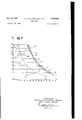
Fig. '7 is a graphical representation of the various values of the leading angle of the blade at various points along its length R;
Fig. 8 is a partia1 perspective view of a blade constructed in accordance with the invention and provided with means for neutralizing the effect of centrifugal force on the blade;
Fig. 9 is a sectional view taken approximately along the line XXIX-XIQX of Fig. 8 and Fig. 10 is a diagrammatic view of a modified form of the construction shown in Fig. 8.
Referring now to the drawing, particularly to Figs. 1 and 2, the device comprises a hub M whereon the central rigid body I2 of the vane is fixed, having in front an adjustable leading flap I3, and at its rear an adjustable trailing flap 5--6. Both flaps I3 and 5-6 are articulated to the main body I2. The trailing flap 5-6 oscillates about an axle 4 supported by a small plate 4. A control device I perpendicular to the wind is fitted on a rod 89i8 guided in bearings Hi---! I carried by a plate 1 secured to the central rigid body l--2 of the vane.
At point 9, the rod is connected by means of a link 9|2 to the trailing edge 5--6. This flap is held in its locked position by a spring I3I4 the fastening point M of which, secured on plate I, being thereby fixed with respect to the central rigid vane body l2.
At a point I5 of plate I, there is pivotally secured to the rigid central vane body I-Z a bell-crank lever I6I'I, its one end it being connected by means of a link Iii- 3 to the front part of the adjustable leading flap I3, whereas its other end I1 is situated within the path of the body provided with the control device I when the same is pushed backwards under the pressure of the wind (represented by arrow F.)
If need be, the adjusting of the articulated flaps l,3--5,5 in response to displacements of the control device I, may be effected by means of an intermediate servo-mechanism. The mechanisms interconnecting the leading and the trailing flaps as shown in Figs. l-G are simpler than those according to Figs. 1-2. However, they are substantially equivalent and may be easily understood by reference to the drawing.
The illustrated device works as follows:
So long as the wind velocity is small, all parts are in their positions as shown in Fig. 1. The angle of incidence A between the direction of the wind and the chord connecting the leading front edge and the trailing rear edge of the vane flaps is at its maximum, and the maximum pressure is exerted upon the vane. When the wind velocity increases, the pressure upon the control device I also increases and this area yields leeward. The effect of this displacement is first to lift the trailing flap 5-6 so as to reduce the angle of incidence A and then after a while, when the control device I reaches the vertical end I! of the driving lever pivoted at I5, the link I6-3 also lifts the leading flap !-3 and both these effects combine to decrease angle A more rapidly.
As already said above, the pitch of the vane must be adapted at every one of the points of its length not only to the wind velocity, but also to the circumferential speed of the vane at each point, for it is the relative wind speed resulting from these two speeds which determines the working conditions of the vane. For an airplane propeller of small diameter, it is assumed that it is sufficient to adapt the pitch exactly to the conditions prevailing at one point of its blade which is situated at a distance from its hub equal to about three quarters of the length of said blade. However, for a wind motor wheel the diameter of which may be 50 meters and more, the differences between the values of the circumferential speeds at various points of the vane are of a magnitude such that if the pitch of an entire vane were adapted exactly to the conditions of one particular point of its length, the result would be that a part of the vane would tend to accelerate the rotation, while other parts of the vane would tend to slow the propeller. This is shown in Fig. 7 where curves C1 and C2 represent respectively, for wind velocities of 8 in./sec. and 20 m./sec., the values which the angle of incidence A of the vane (abscissae) should have at various distances from the hub (ordinates). In the case of a variable pitch vane without articulated flaps (curve G1 which corresponds to a wind velocity of 8 m./sec.), when the same is exposed to the action of a wind of 20 m./sec., the adaptation of the angle of incidence that is produced by a simple rotation of the rigid blade about its longitudinal axis, becomes exact in one point only, this point being situated at a distance equal to three quarters of the length of the vane. Now a curve C1 may be established which is practically parallel with the curve C1, and which passes through M. The rotation of the vane about its longitudinal axis results in a uniform increase (with eventual decrease) of the angle of incidence of the entire vane or in other words, it results in shifting of curve C1 in the diagram parallel to itself. Accordingly, if an exact adaptation of the angle of incidence is required for a certain point, curve C1 is to be shifted in the diagram parallel to itself until it intersects the curve C2 at that point, i. e. the vane must be rotated by an angle the value of which is determined by the value of shifting of curve C1. It is Obvious that for every abscissa (i. e. distance of the point from the wheel hub center) another angle or rotation of the vane about its longitudinal axis is required. Fig. 7 proves, that there may be two points of intersection of curves C1 and. C2 so that the variations in the necessary amount of rotation of the vane may be positive as well as negative ones (above and below the point of intersection as represented in Fig. '7 which shows the shifting of curve C1 into the position C'1 where it intersects curve C2 at M, the ordinate for which corresponds to R 18.5 m. i. e. to three quarters of the vane length of 25 meters. It can be seen then that the part of the vane which is beyond M tends to accelerate the wheel and the part below M tends to slow it down.
The adjustment of the angle of incidence of the vane must vary accordingly to the variation of the distance of different points of the vane from the hub. To this end the front flap and trailing flap for each vane of the wheel according to the invention are subdivided (Fig. 3) in a number of independent sections 28-24-25- 26 I9-20-2I--22 each having, for instance, a length of 5 meters and each being provided with a separate adjusting device. Under these conditions, when sections C3, C4, C5, C6 of the curve 01 are considered, these sections corresponding to 5 meter lengths of individual flaps (see Fig. 3), it becomes obvious that the individual adjustment of the angle of incidence for the sections results in a parallel displacement of the corresponding curve sections individually. When the adjustment is made so as to adapt the angle of incidence exactly at the center points m, m, m", m' of the indiw'dual flap portions, curves C's C'4, C's, C's will result for a wind velocity of 20 m./sec., the plurality of curves varying very little from the exact curve C2 that interconnects points m, m, m". m, which correspond to the precise adaptation at each point of the vane length.
It is of interest to make possible the varying of the values of the constant speed and output of the vane. To that end it is suificient to alter one of the elements which determine the adjustment of the deflection of the articulated flaps.
According to another feature of the invention the wind pressure upon the control device I may be used to control a mechanical or electrical transmission device whereby the direction of the axis of rotation of the wind motor may be changed with respect to the direction of the wind, the eiiective area exposed of member 1 being altered by such means.
Certain improvements will now be described, the purpose of which is to facilitate the starting of the motor at a small wind velocity and to provide for a better adaptation of the pitch of the vanes with respect to the variations of the wind speed so as to obtain the maximum output, etc.
As shown in Fig. 4, each vane according to the invention consists of a rigid center part IOI fixedly secured to the hub, the most favorable angle of incidence for agiven wind velocity having been established to correspond to conditions prevailing within each subdivision of the length of the vane, for instance 8 m./sec. There is a leading flap 02 and a trailing flap I03 articulated upon supports E04, I05, respectively, which are integral with the rigid center part IOI. The displaceable parts I02 and I03 of the vane are operated by a displaceable control area I06 subiect to prevailing wind pressure, this area I06 may, for example, pivot about an axis I01 provided upon support I04. Area I06, yielding under the wind pressure, acts either by means of an intermediate lever I00 integral therewith in its rotation and imparts its movement by means of link I09 to the leading flap I02, the displacement of which is transmitted by means of link II 0 to the trailing flap I03. An antagonistic spring HI having one end secured upon link H0 and its other end fixed upon the rigid center vane part IOI, pulls both flaps I02 and I03 into their no Wind position as shown in Fig. 4, i. e. the leading flap I02 is turned forward (in the windward direction) whereas the trailing flap !03 is turned in its rearward direction (opposite to that of the deflection of the leading flap).
It is evident that under these conditions, when there is no wind or when the wind is weak (Fig. 4), the flaps I02 and I03 are pulled by the action of the antagonistic spring II I into the position of their maximum deflection, one forward, the other backward, with respect to the rigid center part IOI. In order to increase the effective force further, particularly in a small wind, and especially for starting the motor, the leading flap I02 may be provided with a slit IIZ, the shape of which is similar to that of the interval between two blades of a turbine, a strong depression on the back face of the profile being produced when air is flowing through, this being a well known means of producing a strong lifting component CZ.
When the wind velocity increases, the displacement of the yielding area I06 against the action of spring III causes the flaps I02 and I03 to pivot in the direction of arrows f, f' and to align themselves as extensions of the rigid center part IOI when the wind velocity reaches the datum velocity, for instance 8m./sec. (position shown in Fig. 6).
Now, when the wind velocity exceeds the datum velocity to which the angle of incidence of the vane has been adapted, the action of the wind on the movable area I06 causes a backward deflection of the leading flap I02 and a forward deflection of the trailing flap I03 (Fig. 6).
The complete and general solution of the problem would be after having designed the various sections with small angles of incidence appropriate to starting conditions, to twist the vane while the motor is rotating, the twist being more pronounced as the respective circumferential spwd increases and especially as the distance of the section under consideration from the hub increases, or if the wind speed actually weakens, as the relationship decreases. It is obvious that a rigid vane or one which is rigidly stationary can be adapted only poorly in all its sections except perhaps by chance and in one section where coincides with the datum. relationship. It is also apparent that a rigid vane capable of a certain rotation about a longitudinal axis along its entire length from the hub to the circumference can be momentarily and correctly adapted for one single selected section only, wherein the working conditions may be optimal ones, while the adaptation for all other sections will remain only an approximate one and even roughly approximate, being insufficient near the hub and in excess at the end of the vane.
The ideal but practically not attainable solution would consist in decomposing the vane into an infinite number of sections each of them being adjusted separately. The intermediate solution, according to the invention and which is effective for propeller blades, and for wind motor vanes as well, consists in two separate expedients:
1 (The radial division of flaps). The vane is designed so as to consist of a number (generally three) parts every one of which may be deflected and/or adjusted so as to make the middle section of each part correspond exactly to the conditions prevailing at its respective distance from the hub, e. g. for a 25 meter vane there could be provided a first rigid, non adjustable part extending from 0 to 5 meters, this part running practically idle even under most favorable conditions of adaptation; a second part extending from to meters, the same being adjusted exactly in its middle section, 1. e. the one at the distance of 7.5 meters from the rotation axis, a third part extending from 10 to meters adjusted exactly in a point at a distance of 12.5 meters from the axis of rotation, etc.
In this way the lack of precision in the adaptation of the parts of each section other than their middle (central) sections will in general approach very closely the exact positions of every section at all distances from the hub of the motor.
2 (The tangential division of flaps). It has been mentioned that according to the invention, each vane consists of a main rigid center part having a leading edge and a trailing edge provided with flaps aligned in radially adjacent position so that the extreme edges of the flaps form the real leading and trailing edges of each vane. The number of fiaps on the leading edge is equal to that on the trailing edge and they are interconnected into pairs so that each movement of one of the leading edge flaps is accompanied by a displacement of the conjugated trailing edge flap (connecting rod H0 in Figs. 4-6 or numbers I32, l3! in Fig. 8). As shown in the drawings, opposite rotations are applied to the leading edge flaps in relation to those of the trailing edge flaps, the value of these displacements being determined either by special devices (e. g. 1 in Figs. l-2, or H36 in Figs. 4-6) arranged to yield under the wind pressure exerted thereupon or, as in the embodiment according to Figs. 8-10, it may be the leading edge flap (I32) itself the position whereof is entirely controlled by the direction of the relative wind, the leading edge flap determining then precisely the deflection of the trailing edge flap.
Under starting conditions the direction of the relative wind velocity is identical with V, the actual wind velocity. Its angle of incidence uponthe chord of zero lift of the pure profile, i. e. the profile without deflection, would then be considerable and would exceed appreciably the incidence of the maximum lift, so that the CZ lift component, which at this instant is the same as the rotation impulse, would be very small, and accordingly it would be impossible or at least extremely difficult to start.
The extreme usefulness of the deformation of the profile by means of double deflection, as described, for the starting torque becomes evident. Incidentally, it should be noted that it is the foot of the vane, that is to say the region which is nearest to the hub, which supplies the most effective partial forces of rotation for starting owing to the reduction of the angle of incidence to values which are not too high, While the parts in the neighborhood of the end of the vane supply partial rotation impulses which are practically non existent owing to the too high value of the angle of incidence in that part which is still much too high despite the double deflection.
The foregoing explanation of the phenomena occurring at the starting moment helps to understand how the double deflection of the leading and trailing flaps articulated upon the rigid center part is equivalent to a supposed rotation of the whole profile.
Afterwards, once the motor is rotating, its speed of rotation begins to modify the value and direction of the relative wind velocity and to reduce the angle of incidence to a value which can now decrease below the angle of incidence corresponding to maximum lift.
Under the effect of this impulse the engine accelerates its rotation steadily so as to attain certain conditions corresponding to a certain number of revolutions at which the rotation becomes constant as long as the wind itself remains constant. It can be noted that design characteristics have been established so as to obtain a maximum output for these normal conditions. This means that an angle of incidence is to be established for each section under consideration; the angle may be rather wide but it will be smaller than the angle of maximum lift.
After such normal conditions have been reached the absolute and the relative wind velocity may increase, which results in an increase of the angle of incidence. It may happen eventually that this angle exceeds the angle of incidence of maximum lift, so that the rotation impulse component begins to diminish. An increase in the speed of rotation is avoided in this Way and therefore a partial self regulation by sections having such a high value of the angle of incidence will be exerted.
It is evident that even if normal conditions are prevailing, the relative velocity, which is already high (owing to an increase in the absolute Wind speed), will exert upon the control area H36 a greater pressure and therefore will deflect the leading edge flap into the windward direction (whereas the trailing edge flap is positively deflected simultaneously in the leeward, i. e. the opposite direction); in this way a corresponding diminution of the angle of incidence will be effected.
Thus, it can be seen that the effect of an increase in the wind velocity will first have a moderate tendency to increase the angle of incidence and that the same will change thereafter to an opposite tendency so as to reduce the angle of incidence, this decrease of the angle of incidence being itself accompanied by an acceleration of the motor. These changes will have a secondary effect of retarding the final tendency to accelerate the wheel. These secondary effects are helped by the inertia of the mass of the wheel as a whole so that there will be ample time for the control device to act upon the deflecting mechanism of the leading and trailing flaps and to bring them into the positions corresponding to the correct angle which is required if the optimal working conditions of the wheel are to be maintained.
By way of example, a vane may be considered which is adapted to run at a wind velocity of 8 meters per second under working conditions making 4 of a revolution in a second, with an angle of incidence of 7 for a radius 5:20 In. Should the velocity of the wind rise to 9 m./sec., the vane will tend momentarily to attain an angle of incidence of about 845; now its output will increase to 1.42 times the original one under working conditions of 0.387 revolutions per sec., with an angle of incidence of about 345 the-leading edge flap is deflected backward and the trailing edge flap forward. The original output and working conditions will be maintained by bringing the angle of incidence back to about this state corresponds to an increase of the angle of a little more than 2.
Obviously this maintenance of the working conditions for an increased wind velocity implies that the surplus output motivated by this increase in the wind speed is lost.
The operation of the system in the case of decreasing wind velocity can be explained in similar manner. However, should the eificiency under normal conditions be optimal for a datum wind velocity, it will be naturally impossible to keep it up for a decreasing wind since then the energy supplied and therefore also the output energy will be smaller than the energy obtained in the previous case. In order to be able to maintain the working conditions it will be necessary to admit a lesser efficiency for a datum wind velocity than for the smaller wind velocity. In this case the correction for the angle of incidence will be made in the direction opposite to that of the correction made for an increased wind, that is in turning the leading edge flap in the windward direction, i. e. forward.
If need be, cams may be introduced in the system of the gear rods so as to obtain the required relations within the connecting means more easily or more accurately.
The present improvements of the invention would find with advantage application in airplane propeller blades for the purpose of modifying the pitch of the propellers either at the time of starting or during a flight. And in the same manner the structure of the invention would be particularly suitable for the blades for helicopters or gyroplanes.
The propeller blades provided with such im provements and with the following improvement can be articulated on the hub in known manner.
The object of a last improvement is to suppress the detrimental effects of centrifugal force on the wind testing area I32 (see Figs. 840). In fact the position taken by this device depends not only upon the action of the wind on it but also upon that of centrifugal force.
This last improvement consists in neutralizing the centrifugal force effects upon the wind testing area by associating therewith a movable mass equal to the mass of the body with the wind testing area and which is subjected to a centrifugal stress equal and opposite to the stress exerted upon the area itself. Thus the centrifugal and compensating stresses will be neutralized.
According to the embodiment of this improvement shown in Figs. 8 to 10, the rigid central part of vane I33, secured to the hub, is provided with an articulated trailing flap I3I. The position of this trailing flap I3I is determined by a corresponding wind testing area I32 in the form of a warped flap fitted like a wind vane on an axle I33 and maintained in front of the leading edge of the central body I33 and parallel to its general direction by two members I3 l-I33.
It can be seen in Fig. 9 (showing a transverse diagrammatical sectional view of vane I30 along plane XXIX in Fig. 8) that the testing area I32 is disposed at an angle to the direction of zero lift. Said angle is the leading angle of the relative wind; its variations or the values connected therewith, such as for instance, the variations of the angle by which the area I32 is disposed are used to produce the required deflection of the trailing flap I3I by means of any appropriate and 10 direct transmission or through an intermediate power servo-mechanism, or with intermediate interchangeable cams to modify the deflection according to prevailing conditions.
However to make this arrangement work correctly, the position of the wind testing area I32 must be independent from any directing effect due to centrifugal force on account of the fact that axle E33 parallel with the windward edge of the central rigid vane body I33 is not exactlyperpendicular to the rotation axis of the motor. To avoid said inconvenience a second axle I33 has been provided (Fig. 10) e. g. within the central rigid vane body I33 said second axle I36 being parallel with axle I33 of the wind testing area I32. Said two axles I33 and I43 carry two parallel fingers or segments I37, I33 interconnected e. g. by means of a cable I39; axle I33 carries a mass I33 the position of which with respect to the axle is arranged symmetrically to that of the center of gravity of the testing area I32 with respect to its own axle I33, their weights being equal. The moments of rotation due to the centrifugal force on the testing area I32 and upon the balancing mass are equal and opposite; the wind testing area I32 is therefore relieved of this directing stress of the centrifugal force and its direction gives exactly the relative direction of the wind.
What we claim is:
l. A wind motor comprising a propeller having a plurality of blades extending radially from the axis of said propeller, at least one series of airfoil elementary corrective members pivotally mounted on at least one edge of each of said blades, and disposed in radially adjacent position along the radial length of each of said blades, each member of each series being movable independently of the other members, an adjustment device for each of said members responsive to changes in wind velocity, each adjustment device being mounted in the same general radial portion of the blade in which the corresponding corrective ngember is pivotally supported, whereby each adjustment device is exposed to substantially the same Wind which acts upon the corresponding corrective member, and means for connecting each of said adjustment devices to each corresponding corrective member for automatically varying the position of said corresponding corrective member upon each displacement of said device by changing wind velocity.
2. A wind motor as defined in claim 1, wherein each of said adjustment devices comprises a pivotally-mounted wind feeler.
3. A wind motor as defined in claim 1, wherein each of said adjustment devices comprises a pivotally-rnounted elongated wind feeler having a wind engaging surface substantially parallel to the edge of the associated blade.
4. A wind motor as defined in claim 1, wherein each of said adjustment devices comprises a pivotally-mounted wind feeler, and means for compensating the centrifugal strain to which said feeler is submitted upon rotation of the propeller.
5. A wind motor as defined in claim 4, further comprising for each centrifugal stress compensating means on each wind feeler, a pivotallyn ounted arm having a pivot axis parallel to the pivot axis of the feeler and having a compensatng mass disposed at its end, and means connecting the feeler and the pivoting arm whereby the centrifugal stresses to which the feeler and com- 11 12 pensating mass are subjected are opposed and Number Name Date balanced. 2,135,887 Fairey Nov. 8, 1938 RENE LOUIS PIERRE MARIE CHEVREAU. 2,153,523 Roberts Apr. 4, 1939 PAUL JULIEN DEV'ILLE. 2,272,664 Grapler Feb. 10, 1942 5 2,358,967 Everts Sept. 26, 1944 REFERENCES CITED 2,454,440 Foulston Nov. 23, 1948 The following references are of record in the FOREIGN PATENTS file of this patent Number Country Date NI STATES PATENTS 10 260,970 Italy Oct. 24,1928 Number Name t 388,827 Great Britain Mar. 9, 1933 1,266,518 Mulrony May 14, 1918 482,607 Germany Sept- 1929 1,874,053 Lambert Aug. 30, 1932 545,288 France y 18, 1922 2,095,734 Dornier Oct. 12, 1937
Applications Claiming Priority (1)
| Application Number | Priority Date | Filing Date | Title |
|---|---|---|---|
| FR2622686X | 1942-07-21 |
Publications (1)
| Publication Number | Publication Date |
|---|---|
| US2622686A true US2622686A (en) | 1952-12-23 |
Family
ID=9687286
Family Applications (1)
| Application Number | Title | Priority Date | Filing Date |
|---|---|---|---|
| US11744A Expired - Lifetime US2622686A (en) | 1942-07-21 | 1948-02-27 | Wind motor |
Country Status (1)
| Country | Link |
|---|---|
| US (1) | US2622686A (en) |
Cited By (51)
| Publication number | Priority date | Publication date | Assignee | Title |
|---|---|---|---|---|
| US2716460A (en) * | 1952-02-28 | 1955-08-30 | Raymond A Young | Blade and control mechanism for helicopters |
| US3163231A (en) * | 1963-04-29 | 1964-12-29 | United Aircraft Corp | Two-part pitch changing mechanism |
| US3874816A (en) * | 1973-10-23 | 1975-04-01 | Thomas E Sweeney | Windmill blade |
| US3877836A (en) * | 1974-08-13 | 1975-04-15 | Leo L Tompkins | Horizontal windmill |
| US3995972A (en) * | 1975-07-07 | 1976-12-07 | Nassar Esam M | Wind machine with reciprocating blade means |
| US4003676A (en) * | 1973-10-23 | 1977-01-18 | Sweeney Thomas E | Windmill blade and processes related thereto |
| US4137009A (en) * | 1976-11-05 | 1979-01-30 | Board Of Regents University Of Nevada System | Pivoted blade barrel rotor wind turbine |
| US4178127A (en) * | 1975-08-27 | 1979-12-11 | Zahorecz Zoltan P | Variable pitch impeller |
| US4286922A (en) * | 1978-10-18 | 1981-09-01 | Lew Hyok S | Variable camber fluid power machine |
| US4297076A (en) * | 1979-06-08 | 1981-10-27 | Lockheed Corporation | Wind turbine |
| US4557666A (en) * | 1983-09-29 | 1985-12-10 | The Boeing Company | Wind turbine rotor |
| US4565929A (en) * | 1983-09-29 | 1986-01-21 | The Boeing Company | Wind powered system for generating electricity |
| US4571156A (en) * | 1984-03-05 | 1986-02-18 | D. C. Research, Inc. | Air foil with trailing spoiler |
| US4575309A (en) * | 1983-05-25 | 1986-03-11 | James Howden & Company Ltd. | Wind turbines |
| US4877374A (en) * | 1988-04-26 | 1989-10-31 | Bill Burkett | Self-regulating windmill |
| US5096378A (en) * | 1989-01-17 | 1992-03-17 | Howden Wind Turbines Limited | Control of a wind turbine |
| WO1994001325A1 (en) * | 1992-07-09 | 1994-01-20 | Northern Power Systems, Inc. | Wind turbine rotor aileron |
| EP0638726A1 (en) * | 1993-08-02 | 1995-02-15 | Hudson Products Corporation | Fan blade |
| US5527152A (en) * | 1994-03-04 | 1996-06-18 | Northern Power Systems, Inc. | Advanced wind turbine with lift cancelling aileron for shutdown |
| US5527151A (en) * | 1992-03-04 | 1996-06-18 | Northern Power Systems, Inc. | Advanced wind turbine with lift-destroying aileron for shutdown |
| US6478541B1 (en) * | 2001-08-16 | 2002-11-12 | The Boeing Company | Tapered/segmented flaps for rotor blade-vortex interaction (BVI) noise and vibration reduction |
| US20040105752A1 (en) * | 2000-12-23 | 2004-06-03 | Aloys Wobben | Rotor blade for a wind power installation |
| FR2863320A1 (en) * | 2003-12-09 | 2005-06-10 | Ocea Sa | Wind generator`s blade for producing electricity, has main body and rotating flap that rotates with respect to main body around rotation axis parallel to trailing edge of blade |
| EP1585665A1 (en) * | 2003-01-23 | 2005-10-19 | Bell Helicopter Textron Inc. | Proprotor blade with leading edge slot |
| US20070003403A1 (en) * | 2003-05-05 | 2007-01-04 | Lm Glasfiber As | Wind turbine blade wirh lift-regulating means |
| US20070036657A1 (en) * | 2003-04-28 | 2007-02-15 | Aloys Wobben | Rotor blade for a wind power system |
| EP1772623A1 (en) * | 2005-10-10 | 2007-04-11 | General Electric Company | Active flow control for wind turbine blades |
| US20070264121A1 (en) * | 2006-05-10 | 2007-11-15 | Miller James W | Torsion blade pivot windmill |
| US20070297896A1 (en) * | 2002-06-05 | 2007-12-27 | Aloys Wobben | Rotor blade for a wind power plant |
| US20090285682A1 (en) * | 2008-05-16 | 2009-11-19 | Frontier Wind, Llc | Wind Turbine With Deployable Air Deflectors |
| US20090284016A1 (en) * | 2008-05-16 | 2009-11-19 | Frontier Wind, Llc | Wind turbine with gust compensating air deflector |
| DE102009013161A1 (en) | 2009-03-16 | 2010-09-23 | Hansbernd Berzheim | Hub-airfoil system e.g. video system and camera system, for controlling e.g. wind energy, in wind turbine, has energy convertors and energy storing device arranged under base of base body in closed housing |
| US20100260603A1 (en) * | 2009-04-13 | 2010-10-14 | Frontier Wind, Llc | Variable Length Wind Turbine Blade Having Transition Area Elements |
| US20100310372A1 (en) * | 2009-06-08 | 2010-12-09 | Vestas Wind Systems A/S | Actuation of movable parts of a wind turbine rotor blade |
| US20110064582A1 (en) * | 2008-05-30 | 2011-03-17 | Ignacio Romero Sanz | Wind turbine blade with high-lift devices |
| EP2307703A1 (en) * | 2008-05-27 | 2011-04-13 | FO900 Invest APS | Blade for a rotor of a wind or water turbine |
| US20110110777A1 (en) * | 2007-12-21 | 2011-05-12 | Vestas Wind Systems A/S | Active flow control device and method for affecting a fluid boundary layer of a wind turbine blade |
| US20110135477A1 (en) * | 2009-12-30 | 2011-06-09 | Omer Mohammed | Method and Apparatus for Increasing Lift on Wind Turbine Blade |
| US20110142681A1 (en) * | 2010-07-21 | 2011-06-16 | General Electric Company | Rotor blade assembly |
| WO2011000628A3 (en) * | 2009-06-30 | 2011-07-28 | Vestas Wind Systems A/S | Improved wind turbine blade control |
| US20110255972A1 (en) * | 2010-04-09 | 2011-10-20 | Gift Technologies, Llc | Multi-element wind turbine airfoils and wind turbines incorporating the same |
| US20120107117A1 (en) * | 2009-05-19 | 2012-05-03 | Vestas Wind Systems A/S | Wind turbine and a blade for a wind turbine |
| WO2011141444A3 (en) * | 2010-05-10 | 2012-05-03 | Technische Universität Darmstadt | Invention relating to rotor blades, in particular for wind power installations |
| US20130028733A1 (en) * | 2010-10-08 | 2013-01-31 | Mccune Earl | Wind turbine having flow-aligned blades |
| US20130052033A1 (en) * | 2010-04-27 | 2013-02-28 | Lm Glasfiber A/S | Wind turbine provided with a slat assembly |
| US20130156593A1 (en) * | 2011-12-16 | 2013-06-20 | General Electric Company | System and method for root loss reduction in wind turbine blades |
| EP2778400A3 (en) * | 2013-03-15 | 2014-12-24 | Frontier Wind, LLC | Actuation of distributed load management devices on aerodynamic blades |
| DK178410B1 (en) * | 2010-11-11 | 2016-02-08 | Gen Electric | Active control of a wind turbine blade |
| US20160131107A1 (en) * | 2013-06-07 | 2016-05-12 | 3 Phase Energy Systems, Inc | Wind Generator with Lightweight Adjustable Blades |
| US9394046B2 (en) | 2011-11-16 | 2016-07-19 | Ecological Energy Company | Fluid interface device as well as apparati and methods including same |
| US11428204B2 (en) | 2017-10-24 | 2022-08-30 | Wobben Properties Gmbh | Rotor blade of a wind turbine and method for designing same |
Citations (11)
| Publication number | Priority date | Publication date | Assignee | Title |
|---|---|---|---|---|
| US1266518A (en) * | 1915-09-03 | 1918-05-14 | Marion Alvin Mulrony | Wind-power motor. |
| FR545288A (en) * | 1921-12-28 | 1922-10-09 | Rotary helicopter | |
| DE482607C (en) * | 1929-09-17 | E H Claudius Dornier Dr Ing | Helicopter plane | |
| US1874053A (en) * | 1930-06-21 | 1932-08-30 | Lambert Chandley William | Automatic propeller pitch changer |
| GB388827A (en) * | 1932-05-23 | 1933-03-09 | James Carter Gray | Improvements in and relating to screw propellers and the like |
| US2095734A (en) * | 1933-01-16 | 1937-10-12 | Dornier Claude | Rotor flying machine |
| US2135887A (en) * | 1935-06-07 | 1938-11-08 | Fairey Charles Richard | Blade for airscrews and the like |
| US2153523A (en) * | 1937-03-25 | 1939-04-04 | W N Price | Wind operated electric generator |
| US2272664A (en) * | 1938-08-01 | 1942-02-10 | Messerschmitt Boelkow Blohm | Flap control |
| US2358967A (en) * | 1942-10-06 | 1944-09-26 | Everel Propeller Corp | Variable pitch propeller |
| US2454440A (en) * | 1944-12-18 | 1948-11-23 | Foulston Roy Alexander | Wind electric governor |
-
1948
- 1948-02-27 US US11744A patent/US2622686A/en not_active Expired - Lifetime
Patent Citations (11)
| Publication number | Priority date | Publication date | Assignee | Title |
|---|---|---|---|---|
| DE482607C (en) * | 1929-09-17 | E H Claudius Dornier Dr Ing | Helicopter plane | |
| US1266518A (en) * | 1915-09-03 | 1918-05-14 | Marion Alvin Mulrony | Wind-power motor. |
| FR545288A (en) * | 1921-12-28 | 1922-10-09 | Rotary helicopter | |
| US1874053A (en) * | 1930-06-21 | 1932-08-30 | Lambert Chandley William | Automatic propeller pitch changer |
| GB388827A (en) * | 1932-05-23 | 1933-03-09 | James Carter Gray | Improvements in and relating to screw propellers and the like |
| US2095734A (en) * | 1933-01-16 | 1937-10-12 | Dornier Claude | Rotor flying machine |
| US2135887A (en) * | 1935-06-07 | 1938-11-08 | Fairey Charles Richard | Blade for airscrews and the like |
| US2153523A (en) * | 1937-03-25 | 1939-04-04 | W N Price | Wind operated electric generator |
| US2272664A (en) * | 1938-08-01 | 1942-02-10 | Messerschmitt Boelkow Blohm | Flap control |
| US2358967A (en) * | 1942-10-06 | 1944-09-26 | Everel Propeller Corp | Variable pitch propeller |
| US2454440A (en) * | 1944-12-18 | 1948-11-23 | Foulston Roy Alexander | Wind electric governor |
Cited By (89)
| Publication number | Priority date | Publication date | Assignee | Title |
|---|---|---|---|---|
| US2716460A (en) * | 1952-02-28 | 1955-08-30 | Raymond A Young | Blade and control mechanism for helicopters |
| US3163231A (en) * | 1963-04-29 | 1964-12-29 | United Aircraft Corp | Two-part pitch changing mechanism |
| US3874816A (en) * | 1973-10-23 | 1975-04-01 | Thomas E Sweeney | Windmill blade |
| US4003676A (en) * | 1973-10-23 | 1977-01-18 | Sweeney Thomas E | Windmill blade and processes related thereto |
| US3877836A (en) * | 1974-08-13 | 1975-04-15 | Leo L Tompkins | Horizontal windmill |
| US3995972A (en) * | 1975-07-07 | 1976-12-07 | Nassar Esam M | Wind machine with reciprocating blade means |
| US4178127A (en) * | 1975-08-27 | 1979-12-11 | Zahorecz Zoltan P | Variable pitch impeller |
| US4137009A (en) * | 1976-11-05 | 1979-01-30 | Board Of Regents University Of Nevada System | Pivoted blade barrel rotor wind turbine |
| US4286922A (en) * | 1978-10-18 | 1981-09-01 | Lew Hyok S | Variable camber fluid power machine |
| US4297076A (en) * | 1979-06-08 | 1981-10-27 | Lockheed Corporation | Wind turbine |
| US4575309A (en) * | 1983-05-25 | 1986-03-11 | James Howden & Company Ltd. | Wind turbines |
| US4557666A (en) * | 1983-09-29 | 1985-12-10 | The Boeing Company | Wind turbine rotor |
| US4565929A (en) * | 1983-09-29 | 1986-01-21 | The Boeing Company | Wind powered system for generating electricity |
| US4571156A (en) * | 1984-03-05 | 1986-02-18 | D. C. Research, Inc. | Air foil with trailing spoiler |
| US4877374A (en) * | 1988-04-26 | 1989-10-31 | Bill Burkett | Self-regulating windmill |
| US5096378A (en) * | 1989-01-17 | 1992-03-17 | Howden Wind Turbines Limited | Control of a wind turbine |
| US5527151A (en) * | 1992-03-04 | 1996-06-18 | Northern Power Systems, Inc. | Advanced wind turbine with lift-destroying aileron for shutdown |
| WO1994001325A1 (en) * | 1992-07-09 | 1994-01-20 | Northern Power Systems, Inc. | Wind turbine rotor aileron |
| US5320491A (en) * | 1992-07-09 | 1994-06-14 | Northern Power Systems, Inc. | Wind turbine rotor aileron |
| EP0638726A1 (en) * | 1993-08-02 | 1995-02-15 | Hudson Products Corporation | Fan blade |
| US5527152A (en) * | 1994-03-04 | 1996-06-18 | Northern Power Systems, Inc. | Advanced wind turbine with lift cancelling aileron for shutdown |
| US7204674B2 (en) * | 2000-12-23 | 2007-04-17 | Aloys Wobben | Rotor blade for a wind power installation |
| US20040105752A1 (en) * | 2000-12-23 | 2004-06-03 | Aloys Wobben | Rotor blade for a wind power installation |
| US6478541B1 (en) * | 2001-08-16 | 2002-11-12 | The Boeing Company | Tapered/segmented flaps for rotor blade-vortex interaction (BVI) noise and vibration reduction |
| US7914261B2 (en) | 2002-06-05 | 2011-03-29 | Aloys Wobben | Rotor blade for a wind power plant |
| US8100663B2 (en) | 2002-06-05 | 2012-01-24 | Aloys Wobben | Rotor blade for a wind power plant |
| US20100232972A1 (en) * | 2002-06-05 | 2010-09-16 | Aloys Wobben | Rotor blade for a wind power plant |
| US7708530B2 (en) | 2002-06-05 | 2010-05-04 | Aloys Wobben | Rotor blade for a wind power plant |
| US20070297896A1 (en) * | 2002-06-05 | 2007-12-27 | Aloys Wobben | Rotor blade for a wind power plant |
| US20060239824A1 (en) * | 2003-01-23 | 2006-10-26 | Robertson Daniel B | Proprotor blade with leading edge slot |
| US7594625B2 (en) | 2003-01-23 | 2009-09-29 | Bell Helicopter Textron Inc. | Proprotor blade with leading edge slot |
| EP1585665A1 (en) * | 2003-01-23 | 2005-10-19 | Bell Helicopter Textron Inc. | Proprotor blade with leading edge slot |
| EP1585665A4 (en) * | 2003-01-23 | 2007-09-12 | Bell Helicopter Textron Inc | Proprotor blade with leading edge slot |
| US7946803B2 (en) | 2003-04-28 | 2011-05-24 | Aloys Wobben | Rotor blade for a wind power system |
| US20070036657A1 (en) * | 2003-04-28 | 2007-02-15 | Aloys Wobben | Rotor blade for a wind power system |
| US20070003403A1 (en) * | 2003-05-05 | 2007-01-04 | Lm Glasfiber As | Wind turbine blade wirh lift-regulating means |
| US7293959B2 (en) * | 2003-05-05 | 2007-11-13 | Lm Glasfibeer A/S | Wind turbine blade with lift-regulating means |
| FR2863320A1 (en) * | 2003-12-09 | 2005-06-10 | Ocea Sa | Wind generator`s blade for producing electricity, has main body and rotating flap that rotates with respect to main body around rotation axis parallel to trailing edge of blade |
| EP1772623A1 (en) * | 2005-10-10 | 2007-04-11 | General Electric Company | Active flow control for wind turbine blades |
| US20070231151A1 (en) * | 2005-10-10 | 2007-10-04 | General Electric Company | Active flow control for wind turbine blades |
| US20090191058A1 (en) * | 2006-05-10 | 2009-07-30 | Miller James W | Torsion blade pivot windmill |
| US20070264121A1 (en) * | 2006-05-10 | 2007-11-15 | Miller James W | Torsion blade pivot windmill |
| US20110020133A1 (en) * | 2006-05-10 | 2011-01-27 | Miller James W | Torsion blade pivot windmill |
| US20110110777A1 (en) * | 2007-12-21 | 2011-05-12 | Vestas Wind Systems A/S | Active flow control device and method for affecting a fluid boundary layer of a wind turbine blade |
| US10844837B2 (en) | 2008-05-16 | 2020-11-24 | Ge Infrastructure Technology, Llc | Wind turbine with deployable air deflectors |
| US8267654B2 (en) | 2008-05-16 | 2012-09-18 | Frontier Wind, Llc | Wind turbine with gust compensating air deflector |
| US20090284016A1 (en) * | 2008-05-16 | 2009-11-19 | Frontier Wind, Llc | Wind turbine with gust compensating air deflector |
| US20090285682A1 (en) * | 2008-05-16 | 2009-11-19 | Frontier Wind, Llc | Wind Turbine With Deployable Air Deflectors |
| US8192161B2 (en) | 2008-05-16 | 2012-06-05 | Frontier Wind, Llc. | Wind turbine with deployable air deflectors |
| EP2307703A4 (en) * | 2008-05-27 | 2013-11-13 | Vindtek Torshavn Aps | Blade for a rotor of a wind or water turbine |
| EP2307703A1 (en) * | 2008-05-27 | 2011-04-13 | FO900 Invest APS | Blade for a rotor of a wind or water turbine |
| US20110064582A1 (en) * | 2008-05-30 | 2011-03-17 | Ignacio Romero Sanz | Wind turbine blade with high-lift devices |
| EP2292926B1 (en) * | 2008-05-30 | 2018-10-24 | Gamesa Innovation & Technology, S.L. | Wind generator blade with hyper-supporting elements |
| CN102046963A (en) * | 2008-05-30 | 2011-05-04 | 歌美飒创新技术公司 | Wind generator blade with hyper-supporting elements |
| DE102009013161A1 (en) | 2009-03-16 | 2010-09-23 | Hansbernd Berzheim | Hub-airfoil system e.g. video system and camera system, for controlling e.g. wind energy, in wind turbine, has energy convertors and energy storing device arranged under base of base body in closed housing |
| US8206107B2 (en) | 2009-04-13 | 2012-06-26 | Frontier Wind, Llc | Variable length wind turbine blade having transition area elements |
| US20100260603A1 (en) * | 2009-04-13 | 2010-10-14 | Frontier Wind, Llc | Variable Length Wind Turbine Blade Having Transition Area Elements |
| US9200614B2 (en) * | 2009-05-19 | 2015-12-01 | Vestas Wind Systems A/S | Wind turbine and a blade for a wind turbine |
| US20120107117A1 (en) * | 2009-05-19 | 2012-05-03 | Vestas Wind Systems A/S | Wind turbine and a blade for a wind turbine |
| US20100310372A1 (en) * | 2009-06-08 | 2010-12-09 | Vestas Wind Systems A/S | Actuation of movable parts of a wind turbine rotor blade |
| US8186936B2 (en) * | 2009-06-08 | 2012-05-29 | Vestas Wind Systems A/S | Actuation of movable parts of a wind turbine rotor blade |
| WO2011000628A3 (en) * | 2009-06-30 | 2011-07-28 | Vestas Wind Systems A/S | Improved wind turbine blade control |
| CN102116252B (en) * | 2009-12-30 | 2014-08-06 | 通用电气公司 | Method and apparatus for increasing lift on wind turbine blade |
| US20110135477A1 (en) * | 2009-12-30 | 2011-06-09 | Omer Mohammed | Method and Apparatus for Increasing Lift on Wind Turbine Blade |
| US8303250B2 (en) * | 2009-12-30 | 2012-11-06 | General Electric Company | Method and apparatus for increasing lift on wind turbine blade |
| CN102116252A (en) * | 2009-12-30 | 2011-07-06 | 通用电气公司 | Method and apparatus for increasing lift on wind turbine blade |
| US20110255972A1 (en) * | 2010-04-09 | 2011-10-20 | Gift Technologies, Llc | Multi-element wind turbine airfoils and wind turbines incorporating the same |
| US10352294B2 (en) * | 2010-04-27 | 2019-07-16 | Lm Wp Patent Holding A/S | Wind turbine provided with a slat assembly |
| US20130052033A1 (en) * | 2010-04-27 | 2013-02-28 | Lm Glasfiber A/S | Wind turbine provided with a slat assembly |
| US9353728B2 (en) | 2010-05-10 | 2016-05-31 | Technische Universität Darmstadt | Invention relating to rotor blades, in particular for wind power installations |
| CN102933840A (en) * | 2010-05-10 | 2013-02-13 | 达姆施塔特技术大学 | Invention relating to rotor blades in particular for wind power installations |
| CN102933840B (en) * | 2010-05-10 | 2016-08-03 | 达姆施塔特技术大学 | Relate to the invention of the rotor blade of rotor blade particularly wind turbine generator |
| WO2011141444A3 (en) * | 2010-05-10 | 2012-05-03 | Technische Universität Darmstadt | Invention relating to rotor blades, in particular for wind power installations |
| US8011887B2 (en) * | 2010-07-21 | 2011-09-06 | General Electric Company | Rotor blade assembly |
| US20110142681A1 (en) * | 2010-07-21 | 2011-06-16 | General Electric Company | Rotor blade assembly |
| DE102011051985B4 (en) * | 2010-07-21 | 2020-02-27 | General Electric Company | Rotor blade device |
| US8899921B2 (en) * | 2010-10-08 | 2014-12-02 | Earl McCune | Wind turbine having flow-aligned blades |
| US20130028733A1 (en) * | 2010-10-08 | 2013-01-31 | Mccune Earl | Wind turbine having flow-aligned blades |
| US20150044055A1 (en) * | 2010-10-08 | 2015-02-12 | Earl McCune | Wind turbine having flow-aligned blades |
| US9581132B2 (en) * | 2010-10-08 | 2017-02-28 | Earl McCune | Wind turbine having flow-aligned blades |
| DK178410B1 (en) * | 2010-11-11 | 2016-02-08 | Gen Electric | Active control of a wind turbine blade |
| US9394046B2 (en) | 2011-11-16 | 2016-07-19 | Ecological Energy Company | Fluid interface device as well as apparati and methods including same |
| US8936435B2 (en) * | 2011-12-16 | 2015-01-20 | General Electric Company | System and method for root loss reduction in wind turbine blades |
| US20130156593A1 (en) * | 2011-12-16 | 2013-06-20 | General Electric Company | System and method for root loss reduction in wind turbine blades |
| EP2778400A3 (en) * | 2013-03-15 | 2014-12-24 | Frontier Wind, LLC | Actuation of distributed load management devices on aerodynamic blades |
| US9506453B2 (en) | 2013-03-15 | 2016-11-29 | Frontier Wind, Llc | Actuation of distributed load management devices on aerodynamic blades |
| US10337494B2 (en) * | 2013-06-07 | 2019-07-02 | 3 Phase Energy Systems, Inc | Wind generator with lightweight adjustable blades |
| US20160131107A1 (en) * | 2013-06-07 | 2016-05-12 | 3 Phase Energy Systems, Inc | Wind Generator with Lightweight Adjustable Blades |
| US11428204B2 (en) | 2017-10-24 | 2022-08-30 | Wobben Properties Gmbh | Rotor blade of a wind turbine and method for designing same |
Similar Documents
| Publication | Publication Date | Title |
|---|---|---|
| US2622686A (en) | Wind motor | |
| US4050246A (en) | Wind driven power system | |
| US5529458A (en) | Circulation control aerofoils | |
| US4360315A (en) | Vortex wind turbine | |
| US1786057A (en) | Turbine | |
| US2475121A (en) | Airscrew | |
| US2156994A (en) | Aircraft | |
| US2076520A (en) | Automatic air motor governor | |
| US2581773A (en) | Aircraft rotor blade and blade flap pitch control | |
| US2135700A (en) | Autorotative wing for aircraft | |
| US2070657A (en) | Rotative wing aircraft | |
| US2055928A (en) | Rotating blade means for aircraft | |
| US2650045A (en) | Aircraft | |
| US2399828A (en) | Propeller | |
| US3348618A (en) | Helicopter rotor | |
| US2352186A (en) | Variable pitch propeller | |
| US2475337A (en) | Rotor blade | |
| US1692397A (en) | Helicopter | |
| US1656492A (en) | Flying machine | |
| US1943210A (en) | Automatically variable pitch propeller | |
| EP0018114A1 (en) | Thrust devices | |
| US3077934A (en) | Rotor control system for a helicopter | |
| US2075682A (en) | Screw propeller | |
| US3156437A (en) | Fluid flow straightening device in a propelled body | |
| US2738148A (en) | Method of developing lift from the propeller blades of an airplane |