US20110211971A1 - Rotor blade for a wind power plant, wind power plant and method for the production of a rotor blade - Google Patents
Rotor blade for a wind power plant, wind power plant and method for the production of a rotor blade Download PDFInfo
- Publication number
- US20110211971A1 US20110211971A1 US13/032,261 US201113032261A US2011211971A1 US 20110211971 A1 US20110211971 A1 US 20110211971A1 US 201113032261 A US201113032261 A US 201113032261A US 2011211971 A1 US2011211971 A1 US 2011211971A1
- Authority
- US
- United States
- Prior art keywords
- rotor blade
- belt
- longitudinal extension
- shell
- layer
- Prior art date
- Legal status (The legal status is an assumption and is not a legal conclusion. Google has not performed a legal analysis and makes no representation as to the accuracy of the status listed.)
- Abandoned
Links
- 238000004519 manufacturing process Methods 0.000 title claims abstract description 13
- 238000000034 method Methods 0.000 title claims abstract description 13
- 239000000835 fiber Substances 0.000 claims abstract description 45
- 239000003733 fiber-reinforced composite Substances 0.000 claims abstract description 35
- 239000000463 material Substances 0.000 claims abstract description 30
- 230000007423 decrease Effects 0.000 claims description 10
- 239000011257 shell material Substances 0.000 description 61
- 239000011162 core material Substances 0.000 description 17
- 239000004744 fabric Substances 0.000 description 7
- 238000013461 design Methods 0.000 description 6
- 229920000049 Carbon (fiber) Polymers 0.000 description 5
- 240000007182 Ochroma pyramidale Species 0.000 description 5
- 239000004917 carbon fiber Substances 0.000 description 5
- 229920005989 resin Polymers 0.000 description 5
- 239000011347 resin Substances 0.000 description 5
- 230000007704 transition Effects 0.000 description 5
- 238000005452 bending Methods 0.000 description 4
- 230000008901 benefit Effects 0.000 description 4
- VNWKTOKETHGBQD-UHFFFAOYSA-N methane Chemical compound C VNWKTOKETHGBQD-UHFFFAOYSA-N 0.000 description 4
- 239000002131 composite material Substances 0.000 description 3
- 238000010276 construction Methods 0.000 description 3
- 230000032798 delamination Effects 0.000 description 3
- 238000011161 development Methods 0.000 description 2
- 239000011152 fibreglass Substances 0.000 description 2
- 239000006261 foam material Substances 0.000 description 2
- 239000003365 glass fiber Substances 0.000 description 2
- 238000001802 infusion Methods 0.000 description 2
- 238000005304 joining Methods 0.000 description 2
- 150000001875 compounds Chemical class 0.000 description 1
- 238000005520 cutting process Methods 0.000 description 1
- 230000000694 effects Effects 0.000 description 1
- 239000003822 epoxy resin Substances 0.000 description 1
- 238000003780 insertion Methods 0.000 description 1
- 230000037431 insertion Effects 0.000 description 1
- 238000003475 lamination Methods 0.000 description 1
- 229920000647 polyepoxide Polymers 0.000 description 1
- 239000000047 product Substances 0.000 description 1
- 230000002787 reinforcement Effects 0.000 description 1
- 239000012783 reinforcing fiber Substances 0.000 description 1
- 239000011265 semifinished product Substances 0.000 description 1
- 238000010008 shearing Methods 0.000 description 1
- 229920002994 synthetic fiber Polymers 0.000 description 1
- 239000012209 synthetic fiber Substances 0.000 description 1
- 238000012800 visualization Methods 0.000 description 1
Images


Classifications
-
- F—MECHANICAL ENGINEERING; LIGHTING; HEATING; WEAPONS; BLASTING
- F03—MACHINES OR ENGINES FOR LIQUIDS; WIND, SPRING, OR WEIGHT MOTORS; PRODUCING MECHANICAL POWER OR A REACTIVE PROPULSIVE THRUST, NOT OTHERWISE PROVIDED FOR
- F03D—WIND MOTORS
- F03D1/00—Wind motors with rotation axis substantially parallel to the air flow entering the rotor
- F03D1/06—Rotors
- F03D1/065—Rotors characterised by their construction elements
- F03D1/0675—Rotors characterised by their construction elements of the blades
-
- B—PERFORMING OPERATIONS; TRANSPORTING
- B29—WORKING OF PLASTICS; WORKING OF SUBSTANCES IN A PLASTIC STATE IN GENERAL
- B29C—SHAPING OR JOINING OF PLASTICS; SHAPING OF MATERIAL IN A PLASTIC STATE, NOT OTHERWISE PROVIDED FOR; AFTER-TREATMENT OF THE SHAPED PRODUCTS, e.g. REPAIRING
- B29C70/00—Shaping composites, i.e. plastics material comprising reinforcements, fillers or preformed parts, e.g. inserts
- B29C70/04—Shaping composites, i.e. plastics material comprising reinforcements, fillers or preformed parts, e.g. inserts comprising reinforcements only, e.g. self-reinforcing plastics
- B29C70/28—Shaping operations therefor
- B29C70/30—Shaping by lay-up, i.e. applying fibres, tape or broadsheet on a mould, former or core; Shaping by spray-up, i.e. spraying of fibres on a mould, former or core
- B29C70/302—Details of the edges of fibre composites, e.g. edge finishing or means to avoid delamination
-
- B—PERFORMING OPERATIONS; TRANSPORTING
- B29—WORKING OF PLASTICS; WORKING OF SUBSTANCES IN A PLASTIC STATE IN GENERAL
- B29L—INDEXING SCHEME ASSOCIATED WITH SUBCLASS B29C, RELATING TO PARTICULAR ARTICLES
- B29L2031/00—Other particular articles
- B29L2031/08—Blades for rotors, stators, fans, turbines or the like, e.g. screw propellers
- B29L2031/082—Blades, e.g. for helicopters
- B29L2031/085—Wind turbine blades
-
- F—MECHANICAL ENGINEERING; LIGHTING; HEATING; WEAPONS; BLASTING
- F05—INDEXING SCHEMES RELATING TO ENGINES OR PUMPS IN VARIOUS SUBCLASSES OF CLASSES F01-F04
- F05B—INDEXING SCHEME RELATING TO WIND, SPRING, WEIGHT, INERTIA OR LIKE MOTORS, TO MACHINES OR ENGINES FOR LIQUIDS COVERED BY SUBCLASSES F03B, F03D AND F03G
- F05B2280/00—Materials; Properties thereof
- F05B2280/60—Properties or characteristics given to material by treatment or manufacturing
- F05B2280/6003—Composites; e.g. fibre-reinforced
-
- Y—GENERAL TAGGING OF NEW TECHNOLOGICAL DEVELOPMENTS; GENERAL TAGGING OF CROSS-SECTIONAL TECHNOLOGIES SPANNING OVER SEVERAL SECTIONS OF THE IPC; TECHNICAL SUBJECTS COVERED BY FORMER USPC CROSS-REFERENCE ART COLLECTIONS [XRACs] AND DIGESTS
- Y02—TECHNOLOGIES OR APPLICATIONS FOR MITIGATION OR ADAPTATION AGAINST CLIMATE CHANGE
- Y02E—REDUCTION OF GREENHOUSE GAS [GHG] EMISSIONS, RELATED TO ENERGY GENERATION, TRANSMISSION OR DISTRIBUTION
- Y02E10/00—Energy generation through renewable energy sources
- Y02E10/70—Wind energy
- Y02E10/72—Wind turbines with rotation axis in wind direction
-
- Y—GENERAL TAGGING OF NEW TECHNOLOGICAL DEVELOPMENTS; GENERAL TAGGING OF CROSS-SECTIONAL TECHNOLOGIES SPANNING OVER SEVERAL SECTIONS OF THE IPC; TECHNICAL SUBJECTS COVERED BY FORMER USPC CROSS-REFERENCE ART COLLECTIONS [XRACs] AND DIGESTS
- Y02—TECHNOLOGIES OR APPLICATIONS FOR MITIGATION OR ADAPTATION AGAINST CLIMATE CHANGE
- Y02P—CLIMATE CHANGE MITIGATION TECHNOLOGIES IN THE PRODUCTION OR PROCESSING OF GOODS
- Y02P70/00—Climate change mitigation technologies in the production process for final industrial or consumer products
- Y02P70/50—Manufacturing or production processes characterised by the final manufactured product
Definitions
- the invention relates to a rotor blade for a wind power plant that extends from a rotor blade root substantially to a rotor blade tip, comprising a one-part or multi-part shell that is produced at least partially from a fiber reinforced composite material, and at least one belt that is disposed in the rotor blade substantially in the direction of a longitudinal extension of the rotor blade, where the at least one belt has layers composed of a fiber reinforced composite material having fibers aligned unidirectionally in the direction of a longitudinal extension of the belt.
- the invention further relates to a wind power plant and a method for the production of a rotor blade for a wind power plant.
- Rotor blades for wind power plants are typically constructed from two shells, namely one shell for a suction side of the rotor blade and one shell for a pressure side of the rotor blade.
- the half shells are subsequently joined and bonded.
- the shells for the rotor blades are typically based at least partially on fiber reinforced composite materials.
- a plurality of layers of thin fiber fabrics is used. These can be initially placed dry into a mold and subsequently provided with a resin by means of a resin infusion process.
- so-called “pre-pregs” from “pre-impregnated fibers”
- pre-impregnated fibers pre-impregnated fibers
- these are planar semi-finished products in which the fibers are already embedded in a layer of resin.
- the shell is subjected to a negative pressure and heated so that the resin of the pre-preg layers joins into a firmly bonded resinous compound.
- fabrics of differently oriented fibers are used for the shell.
- the fiber orientation in the layers which are used for assembling the shell is typically ⁇ 45°, that is partly +45° and partly ⁇ 45°, to the longitudinal axis of the rotor blade.
- Such fiber fabrics are also designated as “2AX45” layers.
- the fiber reinforced composites have a high tensile strength in the direction of the fiber orientation due to the glass fibers, carbon fibers or synthetic fibers embedded therein. Therefore the use of “2AX45” layers for the shell of a rotor blade has the result that the shell has a comparatively low rigidity with respect to stresses in the flapwise direction. With this, the shell is resilient with respect to gusts of wind, with which the rotor blade is deflected out of the rotor blade plane. In the process, the rotor blade preferably bends in a direction perpendicular to a plane that is arranged between the leading edge and the trailing edge of the rotor blade airfoil. In an airfoil cross section of the rotor blade, this plane is also referred to as the “chord”.
- the shells In order to absorb these forces, the shells have belts which run in a longitudinal direction of the rotor blade. These belts ensure, in particular, flexural rigidity of the rotor blade, and in combination with webs, which are also disposed and fastened in the interior of the rotor blade, represent the support structure of the rotor blade.
- the belts which absorb and transmit these forces have fiber fabrics that have an orientation in the 0° direction, that is, parallel to the longitudinal axis of the rotor blade.
- Belts in the rotor blade typically run as main belts on the inside of the shell on the suction side and on the pressure side of the rotor blade.
- additional belts that also run in the longitudinal direction of the rotor blade are frequently provided on the leading edge, and if applicable on the trailing edge of the rotor blade. These optional belts absorb bending forces on the rotor blade in the chord plane.
- a main belt in the rotor blade of a wind power plant is typically constructed in either a resin infusion process or from prepreg layers, in order to achieve a longitudinal stiffness necessary for the rotor blade.
- the necessary longitudinal stiffness results from the loads acting on the rotor blade and, for example, the parameter of the tower clearance, i.e. the distance from the rotor blade tip to the outer wall of the tower.
- the parameter of the tower clearance i.e. the distance from the rotor blade tip to the outer wall of the tower.
- different numbers of layers are inserted.
- up to 90 layers of fiber-glass reinforcements are used in a 50 m long rotor blade.
- fiber-reinforced individual layers are usually used that have reinforcing fibers or a fabric made of corresponding fibers, which have a layer thickness of approx. 0.7 mm with a fiber layer weight of approx. 980 g/m 2 made of fiber-glass rovings.
- the hardened laminate made of this fabric has an elasticity modulus in the longitudinal direction of approx. 39,000 N/mm 2 with a fiber volume content of approx. 50%.
- the laminate is hereby preferably formed of epoxy resin. With a layer thickness of 0.7 mm, this yields a longitudinal stiffness of approx. 27,300 N/mm as a product of the elasticity modulus and the thickness of the individual layer.
- the main belt can also have carbon fiber reinforced individual layers, for example, with a thickness of 0.45 mm per individual layer with a fiber areal weight of approx. 500 g/m 2 from carbon fiber rovings and an elasticity modulus in the longitudinal direction in the laminate of approx. 128,200 N/mm 2 .
- a corresponding layer has a stiffness of approx. 57,690 N/mm. Thicker layers with thicknesses of up to 1.5 mm are also used occasionally.
- the main belts, and if applicable, the belts on the leading edge and the trailing edge of a rotor blade usually have a thickness of 3 cm to 8 cm and a width of 5 cm up to 1 m in the area of the blade root and into the rotor blade. Because the bending forces accumulated over the length of the rotor blade from the rotor blade tip to the rotor blade root are dissipated toward the rotor hub, the thickness of the belts is constant toward the rotor blade root. The thickness of the belt decreases gradually toward the rotor blade tip due to the space conditions that narrow gradually, and the lower accumulating bending forces.
- the object of the present invention is to provide a rotor blade and a method for the production of the same, in which a rapid and cost-effective production is associated with a structural strength that is at least equal to, or exceeds, the structural strength of known rotor blades.
- a rotor blade for a wind power plant that extends from a rotor blade root substantially to a rotor blade tip, comprising a one-part or multi-part shell that is produced at least partially from a fiber reinforced composite material, and at least one belt that is disposed in the rotor blade substantially in the direction of a longitudinal extension of the rotor blade, where the at least one belt layer composed of a fiber reinforced composite material has fibers aligned unidirectionally in the direction of the longitudinal extension of the belt, which is further characterized in that a thickness of the at least one belt decreases toward the blade root in a blade root side section whose length amounts to at least 3% of an entire length of the belt, wherein the shell has at least one layer of a fiber reinforced composite material having fibers aligned unidirectionally in the direction of the longitudinal extension of the rotor blade, wherein the layer in at least one section along the longitudinal extension of the rotor blade extends from an airfoil leading edge to an airfoil trailing edge
- the invention is based on the fundamental idea that with the same or increased strength and tensile strength of the rotor blade, material and weight can be saved, and production time for the rotor blade can be shortened by tapering the at least one belt, at the end on the blade root side, already significantly before its end, that is, the thickness of the belt is reduced.
- the lower tensile strength of the belt at the end on the blade root side occurring, as a result, is absorbed by the introduction of a layer composed of a fiber reinforced composite, which also has fibers aligned in the 0° direction and which in a section along the longitudinal direction of the rotor blade extends over the entire extension of the rotor blade from the airfoil leading edge to the airfoil trailing edge.
- Such a layer is also designated as a “full chord UD” layer, where “full chord” stands for the entire chord, that is, the line between the leading edge and the trailing edge of the rotor blade airfoil. And the abbreviation “UD” stands for “unidirectional”, that is, a layer having fibers aligned in one direction parallel to each other.
- This “full chord UD” layer imparts a higher stiffness to the shell in the longitudinal direction that suffices so that the belt can be tapered at the blade root side end. At the same time, the shell does not become significantly heavier. With a blade length of 40 m, the area in which the belt can be tapered to the blade root amounts to at least approx. 1.20 m or at least 3% of the belt length.
- the “full chord” UD layer has the further technical effect that forces which are introduced from the belt into the shell material are distributed extensively over the shell. These stresses are no longer introduced strongly localized into the thin shell material, but rather distributed over a larger surface area. Therefore, the shell also can be dimensioned somewhat thinner than was previously possible, at least in the area of the belt.
- the length of the blade root side section of the at least one belt amounts to at least 10%, in particular at least 15%, in particular at least 20% of the entire length of the belt.
- this can mean a section length of more than 10 m, within which the thickness of the belt decreases towards the blade root. This implies a significant material and cost savings, particularly with the use of carbon fiber composites, in particular if the “full chord UD” layer is produced in contrast from a glass fiber composite.
- the at least one section along the longitudinal extension of the rotor blade in which the layer of a fiber reinforced composite material, having fibers aligned unidirectionally in the direction of the longitudinal extension of the rotor blade, extends from an airfoil leading edge to an airfoil trailing edge of the rotor blade, amounts to at least 10%, in particular at least 30% of a length of the rotor blade.
- the area which is covered by the “full chord UD” layer overlaps the area in which the thickness of the belt decreases.
- the at least one section along the longitudinal extension of the rotor blade in which a layer of a fiber reinforced composite material having fibers unidirectionally aligned in a direction of the longitudinal extension of the rotor blade, extends from an airfoil leading edge to an airfoil trailing edge of the rotor blade occupies at least a range of 15% to 30%, in particular at least from 10% to 50%, in particular from 8% to 80% of a length of the rotor blade. This benefits the stability of the rotor blade.
- the at least one belt has one or more casing layers, composed of a fiber reinforced composite having fibers aligned unidirectionally in the direction of the longitudinal extension of the belt, which substantially completely cover a top side and/or a bottom side of the belt.
- the casing layer encloses or covers the parts of the belt that are constructed of ramp-like stepped layers of fiber reinforced composite.
- the decrease of the thickness of the belt towards the blade tip and towards the blade root is created in the ply design or layer design in that plys or layers of different lengths are applied at successive staggered positions along the longitudinal axis of the rotor blade.
- This has the consequence of steps in the lower and/or upper surface of the belt. In the case of strong stresses, these steps are vulnerable in that the lamination can loosen at the steps such that the layers fray and the integrity of the belt is jeopardized.
- a casing layer overlaps these steps and connects them in turn so they are firmly bonded to each other so that a tear or delamination of an individual layer at its ends is prevented.
- An advantageous embodiment of the invention consists in that the shell or a shell part of the rotor blade has a core that has recesses, extending in the direction of the longitudinal extension of the rotor blade, in which the at least one belt is disposed.
- a core is typically composed of balsa wood or a foam material.
- the inventive belt is embedded in the recesses of the core material, and thus sunk into the shell itself.
- the core and the at least one belt are connected to the at least one layer of fiber reinforced composite material having fibers aligned unidirectionally in the direction of the longitudinal extension of the rotor blade which extends at least in sections from the leading edge of the airfoil to the trailing edge of the airfoil of the rotor blade.
- the core is directly covered by the inventive full chord UD layer.
- the stresses, which were absorbed by the belt, are therefore directly introduced into the full chord UD layer and distributed on this on the rotor blade. In this manner, point source loads of the shell material are avoided.
- the core with the at least one belt disposed in its recess is embedded on both sides in the one-part or multi-part shell.
- This embodiment results in a sandwich design in which on the outside and inside of the shell a fiber composite material having layers, for example, “2AX45” layers, is used between which the core is disposed with the belt embedded therein.
- the at least one belt is disposed on an inside of the one-part or multi-part shell.
- the inside of the respective side of the shell is understood to represent the inside in the manufactured rotor blade, and it typically has a concave curvature. This manner of construction is simpler and faster to produce, at least if neither core nor belt are present in the interior of the shell, because the shell can already be completed before the belt is attached at the inside of the shell, in the finished state or layer by layer.
- the at least one belt is connected to the at least one layer of fiber reinforced composite material having fibers, aligned unidirectionally in the direction of the longitudinal extension of the rotor blade, which extend at least in sections from the airfoil leading edge to the airfoil trailing edge of the rotor blade.
- point source loads that the belt exerts on the shell material are introduced broadly in the shell material, and thus damaging point source loads are reduced or avoided in the shell.
- the object underlying the invention is further solved by a wind power plant having an inventive rotor blade, as described above.
- the object underlying the invention is also solved by a method for the production of a rotor blade for a wind power plant that extends from a rotor blade root substantially to a rotor blade tip, wherein a one-part or multi-part shell is produced at least partially from a fiber reinforced composite material and at least one belt, which is disposed in the rotor blade substantially in the direction of the longitudinal extension of the rotor blade, is produced from layers of a fiber reinforced composite material having fibers aligned unidirectionally in the direction of a longitudinal extension of the belt and is joined to the one-part or multi-part shell, that is developed further in that a thickness of the at least one belt is reduced toward the blade root in a blade root side section, whose length is at least 3% of the entire length of the belt, wherein the shell is provided with at least one layer of a fiber reinforced composite material having fibers aligned unidirectionally in the direction of the longitudinal extension of the rotor blade, wherein the layer in at least one section along the longitudinal extension of the
- the feature of joining the belt to the shell comprises the separate production of the belt and the shell, with the subsequent attachment or insertion of the belt in the shell, as well as the embedding of the belt in the not yet completely produced shell.
- a belt is provided with a casing layer at its lower side and/or its upper side.
- a belt is fastened at an inside of the shell or of a shell part.
- the at least one “full chord UD” layer that is, the at least one layer of fiber reinforced composite material having fibers aligned unidirectionally in the direction of the longitudinal extension of the rotor blade, which extends in at least one section along the longitudinal extension of the rotor blade from an airfoil leading edge to an airfoil trailing edge of the rotor blade, is connected to the belt.
- FIG. 1 a schematic representation of a rotor blade
- FIG. 2 a schematic cross sectional representation through a part of an inventive rotor blade
- FIG. 3 a schematic cross sectional representation through a part of a further inventive rotor blade
- FIG. 4 a a schematic top view of an inventive rotor blade having an inventive belt
- FIG. 4 b a schematic representation of the layers of the belt according to FIG. 4 a ),
- FIG. 4 c a schematic representation of a top view of the root side end of the belt according to FIGS. 4 a ) and 4 b ),
- FIG. 5 a a schematic top view of a further inventive rotor blade having an inventive belt
- FIG. 5 b a schematic representation of the layers of the belt according to FIG. 5 a ),
- FIG. 5 c a schematic representation of a top view of the root side end of the belt according to FIGS. 5 a ) and 5 b ),
- FIG. 6 a a schematic top view of a further inventive rotor blade having an inventive belt
- FIG. 6 b a schematic cross sectional view of an airfoil of the rotor blade according to FIG. 6 a ),
- FIG. 6 c a schematic representation of the layers of the belt according to FIG. 6 a ).
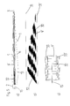
- FIG. 1 schematically shows an inventive rotor blade 1 that has a longitudinal extension from a rotor blade root 2 to a rotor blade tip 3 .
- Airfoil cross sections 4 , 4 ′, 4 ′′ are represented in the rotor blade 1 that are aerodynamically active and have a suction side 7 and a pressure side 8 .
- the aerodynamic airfoil cross sections 4 , 4 ′, 4 ′′ further have an airfoil leading edge 5 and an airfoil trailing edge 6 .
- the airfoil leading edge 5 is also designated as a “nose” of the airfoil.
- FIG. 1 further shows a belt 9 which extends along the longitudinal extension of the rotor blade 1 .
- the belt 9 ends before the tip 3 and before the rotor blade root 2 of the rotor blade 1 . It can be seen in FIG. 1 that the belt adapts to the curve of the rotor blade 1 and is not completely straight. The deviations from the straight line are represented in FIG. 1 for visualization and are represented not to scale and enlarged.
- the belt 9 substantially follows the respective longitudinal extension of the rotor blade 1 . An additional torsion about the longitudinal axis is not represented in the top view.
- FIG. 2 shows in a schematic cross section, a section from an inventive rotor blade 1 .
- This is a cross section through a shell or a half shell of a rotor blade 1 that is comprised of an outer shell part 10 composed of a fiber reinforced composite having “2AX45” layers, that is, fiber reinforced composite layers whose fibers are disposed in two main directions having +45° and ⁇ 45° to the longitudinal axis of the rotor blade 1 .
- a further ply or a further shell part 14 composed of a corresponding fiber reinforced composite having “2AX45” layers is present on the inside.
- the shell parts 10 and 14 enclose a core 11 composed of balsa wood or a foam material that has a recess 12 which runs along the longitudinal direction of the rotor blade 1 extending into the plane of the sheet.
- the inventive belt 9 is inserted into the recess 12 .
- the shapes of the belt 9 and the recess 12 are matched to each other.
- the belt 9 is connected over a large area to the core 11 or to the side walls and to the bottom of the recess 12 of the core 11 .
- a layer 13 having fibers aligned unidirectionally in the direction of the longitudinal extension of the rotor blade 1 a so-called “full chord UD” layer, is located between the core 11 and the belt 9 on one side, and the shell part 14 on the other side. This is connected over a large area to the core 11 , to the shell part 14 , and to the belt 9 .
- the fibers in the layer 13 are aligned parallel to the fibers in the belt 9 , bending loads which are absorbed by the belt 9 are also introduced into the layer 13 , and thus are distributed over a large area between the leading edge and the trailing edge of the airfoil. In this manner, fewer point source loads occur, and the structural integrity of the rotor blade 1 is improved.
- FIG. 3 shows a schematic cross-section of an alternative embodiment.
- An outer shell part 10 ′ composed of a fiber composite material that is formed of layers of “2AX45” fabric, is connected toward the inside directly to a layer 13 having fibers aligned in the direction of the longitudinal axis of the rotor blade 1 .
- a belt 9 is disposed on one side, and is connected to the “full chord UD” layer 13 .
- a further “full chord UD” layer 13 ′ having fibers aligned in the longitudinal direction of the rotor blade 1 , is provided that also encloses the first layer 13 as well as the belt 9 .
- the forces that are absorbed by the belt 9 are more uniformly distributed over the width of the shell or of the shell part 10 ′.
- shearing forces are thereby reduced between the different materials that otherwise could lead to a break or delamination of the belt from the shell material.
- FIG. 4 schematically represents different aspects of the inventive rotor blade 1 .
- the example represented in FIGS. 4 a ) and 4 c ) corresponds to a rotor blade having a length of approximately 40 m.
- FIG. 4 a shows a schematic top view of an inventive rotor blade 1 whose longitudinal axis is marked with the reference numeral 15 .
- a belt 9 which ends before the blade tip 3 and before the blade root 2 , is disposed on the longitudinal axis 15 that runs through the blade root 2 and the blade tip 3 .
- the ends of the individual layers of the belt 9 that are stacked on top of each other are represented by horizontal lines.
- the thickness of the belt 9 also decreases, wherein however, this occurs with a shorter and tighter sequence of layer ends in a ramp 22 which therefore appears dark in FIG. 4 a ).
- the ramp 22 corresponds to a section that has a length of approximately 1.20 m in the longitudinal direction of the rotor blade 1 .
- the rotor blade 1 additionally has a “full chord UD” layer 13 that extends along the entire rotor blade 1 from the leading edge 5 to the trailing edge 6 .
- FIG. 4 b shows a schematic representation of a layer sequence of the layers 20 of the belt 9 from the rotor blade 1 according to FIG. 4 a ).
- the individual layers are each represented with respect to their length, that is, to the starting point and the endpoint along the length of the rotor blade 1 ; all curves, torsions, etc. are not represented. In other words, this is purely a placement plan.
- FIG. 4 b clearly shows that at the root side end, the layers 20 are placed staggered above and behind one another, so that a ramp 22 results.
- the thickness of the belt 9 decreases again by staggered layer ends, wherein however, the decrease of the thickness occurs over a larger longitudinal section.
- two casing layers 21 , 21 ′ are shown that, after construction of the belt with the two layers 20 , are placed over the entire length of the belt 9 , in order to cover the steps, which arise due to the layers being disposed in a staggered or stepped manner, and to prevent them from delaminating.
- the illustration in FIG. 4 b is not true to scale.
- the length of the longest layer is approximately 37 m, while the thickness of the belt 9 in total is approximately 3 cm to 5 cm.
- FIG. 4 c shows a detail section from FIG. 4 a ).
- a top view of the root side end of the belt 9 is shown schematically. The consecutive layer ends that are represented by lines, and that were fused into a dark block in FIG. 4 a ), can be seen clearly.
- the length of the section, in which the ramp 22 is formed centered about the longitudinal axis 15 is approximately 1.2 m.
- the width of the belt 9 is approximately 50 cm.
- Sandwich transitions 23 , 23 ′, having a width of 15 cm to 20 cm, are displaced toward the ends of the ramp 22 , and are composed of balsa wood or a similar lightweight but stable material, and they form a transition from the belt 9 to the shell part lying underneath.
- FIG. 5 shows a further example of the inventive rotor blade 1 having a belt 9 ′.
- the rotor blade has a length of approximately 46 m.
- the belt 9 ′ has a ramp 32 in the area of the blade root 2 that extends over a larger area than in the exemplary embodiment according to FIG. 4 a ).
- approximately 40 layers were used for producing the belt 9
- approximately 54 layers are present.
- the ramp 32 extends over an area of approximately 8 m.
- the reduction of the thickness of the belt 9 ′ towards the blade tip 3 which can be seen in FIG. 5 a ) by the horizontal lines, and is clearly recognizable in the side view in FIG. 5 b ), begins shortly after attaining the maximum thickness at approx. 11 m of the length of the rotor blade and extends over the remainder of the length of the belt 9 ′.
- the belt 9 ′ has a width of approx. 50 cm.
- the belt 9 ′ has a casing layer 31 , 31 ′ on both its top and its bottom that encases the top and the bottom and covers the entire length of the belt 9 ′.
- the sandwich edge and where applicable also the belt 9 come very close to the leading edge 5 and the trailing edge 6 of the rotor blade airfoil, in the direction of the blade tip 3 .
- the belt 9 , 9 ′ and the sandwich transitions 23 , 23 ′, and 33 , 33 ′ are reduced in their length or width at these locations.
- FIG. 6 shows a third exemplary embodiment of the inventive rotor blade 1 , where in turn, FIG. 6 a ) shows a top view of the rotor blade 1 and FIG. 6 c ) shows a side view of a layer plan of a belt 9 ′′ of the rotor blade 1 according to FIG. 6 a ).
- FIG. 6 b shows a cross-section of the rotor blade airfoil along a cross-sectional line A-A from FIG. 6 a ).
- the rotor blade 1 represented in FIG. 6 a is a rotor blade having a length of approximately 50 m.
- the belt has a length of approximately 46 m with more than 70 layers of a unidirectional fiber reinforced composite. At its thickest location, the belt has a thickness of approximately 5 cm to 8 cm.
- the belt according to FIG. 6 has a width of approximately 60 cm and is, as shown in FIG. 6 a ), provided with a balsa border that on both sides has a width of 15 cm to 20 cm.
- a ramp 42 that can be seen in FIG. 6 c ) has a sectional length of approximately 10 m, or more than 20% of the entire belt length.
- the belt 9 ′′ is covered by two casing layers 41 , 41 ′ that cover the stepped ends of the individual layers 40 , and prevent delamination.
- the casing layers 41 , 41 ′ are implemented with two layers at the most heavily loaded area.
- FIG. 6 b shows an airfoil cross section 44 of the rotor blade 1 according to FIG. 6 a ) along a cutting line A-A.
- An airfoil cross section 44 having a thin shell is shown that extends between a leading edge 45 and a trailing edge 46 and has a suction side 47 and a pressure side 48 . It is also shown that in each case a belt 9 ′′ is disposed at both the suction side 47 and the pressure side 48 , that in each case is already connected to the shell at the appropriate location.
- the shell has a “full chord UD” layer 13 on both the suction side 47 and the pressure side 48 that extends at least in sections from the leading edge 45 to the trailing edge 46 .
- One such “full chord UD” layer 13 is provided at the suction side 47 and/or the pressure side 48 .
Abstract
A rotor blade (1) for a wind power plant that extends from a rotor blade root (2) substantially to a rotor blade tip (3), including a one-part or multi-part shell (10, 10′, 14) that is produced at least partially from a fiber reinforced composite material, and at least one belt (9-9′″) that is disposed in the rotor blade (1) substantially in the direction of a longitudinal extension of the rotor blade (1), wherein the at least one belt (9-9′″) has layers composed of a fiber reinforced composite material having fibers aligned unidirectionally in the direction of a longitudinal extension of the belt (9-9′″). Further, a wind power plant and a method for the production of a rotor blade (1) for a wind power plant is described.
Description
- The invention relates to a rotor blade for a wind power plant that extends from a rotor blade root substantially to a rotor blade tip, comprising a one-part or multi-part shell that is produced at least partially from a fiber reinforced composite material, and at least one belt that is disposed in the rotor blade substantially in the direction of a longitudinal extension of the rotor blade, where the at least one belt has layers composed of a fiber reinforced composite material having fibers aligned unidirectionally in the direction of a longitudinal extension of the belt. The invention further relates to a wind power plant and a method for the production of a rotor blade for a wind power plant.
- Rotor blades for wind power plants are typically constructed from two shells, namely one shell for a suction side of the rotor blade and one shell for a pressure side of the rotor blade. The half shells are subsequently joined and bonded.
- The shells for the rotor blades are typically based at least partially on fiber reinforced composite materials. For this purpose, in one possible design a plurality of layers of thin fiber fabrics is used. These can be initially placed dry into a mold and subsequently provided with a resin by means of a resin infusion process. Alternatively, so-called “pre-pregs” (from “pre-impregnated fibers”), that is, pre-impregnated fibers can be used. In this case, these are planar semi-finished products in which the fibers are already embedded in a layer of resin. After the assembly of the shell from pre-pregs, the shell is subjected to a negative pressure and heated so that the resin of the pre-preg layers joins into a firmly bonded resinous compound.
- Typically, fabrics of differently oriented fibers are used for the shell. The fiber orientation in the layers which are used for assembling the shell is typically ±45°, that is partly +45° and partly −45°, to the longitudinal axis of the rotor blade. Such fiber fabrics are also designated as “2AX45” layers.
- If degree values are discussed within the scope of the present invention, for instance 0° or 45°, then in the description of the prior art as well as in the description of the invention it should be implicit that manufacturing specific tolerances and deviations within a few degrees from an exact 0° layer or 45° layer happen and are comprised by the invention. Typical manufacturing tolerances are locally up to 2° to 5°.
- The fiber reinforced composites have a high tensile strength in the direction of the fiber orientation due to the glass fibers, carbon fibers or synthetic fibers embedded therein. Therefore the use of “2AX45” layers for the shell of a rotor blade has the result that the shell has a comparatively low rigidity with respect to stresses in the flapwise direction. With this, the shell is resilient with respect to gusts of wind, with which the rotor blade is deflected out of the rotor blade plane. In the process, the rotor blade preferably bends in a direction perpendicular to a plane that is arranged between the leading edge and the trailing edge of the rotor blade airfoil. In an airfoil cross section of the rotor blade, this plane is also referred to as the “chord”.
- In order to absorb these forces, the shells have belts which run in a longitudinal direction of the rotor blade. These belts ensure, in particular, flexural rigidity of the rotor blade, and in combination with webs, which are also disposed and fastened in the interior of the rotor blade, represent the support structure of the rotor blade. The belts which absorb and transmit these forces have fiber fabrics that have an orientation in the 0° direction, that is, parallel to the longitudinal axis of the rotor blade.
- Belts in the rotor blade typically run as main belts on the inside of the shell on the suction side and on the pressure side of the rotor blade. Optionally, additional belts that also run in the longitudinal direction of the rotor blade, are frequently provided on the leading edge, and if applicable on the trailing edge of the rotor blade. These optional belts absorb bending forces on the rotor blade in the chord plane.
- A main belt in the rotor blade of a wind power plant is typically constructed in either a resin infusion process or from prepreg layers, in order to achieve a longitudinal stiffness necessary for the rotor blade. The necessary longitudinal stiffness results from the loads acting on the rotor blade and, for example, the parameter of the tower clearance, i.e. the distance from the rotor blade tip to the outer wall of the tower. Depending on the size of the rotor blade, different numbers of layers are inserted. Thus, for example, up to 90 layers of fiber-glass reinforcements are used in a 50 m long rotor blade.
- In the construction of the main belts of rotor blades, fiber-reinforced individual layers are usually used that have reinforcing fibers or a fabric made of corresponding fibers, which have a layer thickness of approx. 0.7 mm with a fiber layer weight of approx. 980 g/m2 made of fiber-glass rovings. The hardened laminate made of this fabric has an elasticity modulus in the longitudinal direction of approx. 39,000 N/mm2 with a fiber volume content of approx. 50%. The laminate is hereby preferably formed of epoxy resin. With a layer thickness of 0.7 mm, this yields a longitudinal stiffness of approx. 27,300 N/mm as a product of the elasticity modulus and the thickness of the individual layer.
- Alternatively, the main belt can also have carbon fiber reinforced individual layers, for example, with a thickness of 0.45 mm per individual layer with a fiber areal weight of approx. 500 g/m2 from carbon fiber rovings and an elasticity modulus in the longitudinal direction in the laminate of approx. 128,200 N/mm2. A corresponding layer has a stiffness of approx. 57,690 N/mm. Thicker layers with thicknesses of up to 1.5 mm are also used occasionally.
- The main belts, and if applicable, the belts on the leading edge and the trailing edge of a rotor blade, usually have a thickness of 3 cm to 8 cm and a width of 5 cm up to 1 m in the area of the blade root and into the rotor blade. Because the bending forces accumulated over the length of the rotor blade from the rotor blade tip to the rotor blade root are dissipated toward the rotor hub, the thickness of the belts is constant toward the rotor blade root. The thickness of the belt decreases gradually toward the rotor blade tip due to the space conditions that narrow gradually, and the lower accumulating bending forces.
- The use of fiber reinforced individual layers for producing belts has the advantage of providing high strength and tensile strength of the support structure; however, belts particularly if they are produced from carbon fibers or carbon fiber rovings, are very expensive.
- Therefore, the object of the present invention is to provide a rotor blade and a method for the production of the same, in which a rapid and cost-effective production is associated with a structural strength that is at least equal to, or exceeds, the structural strength of known rotor blades.
- This object is solved by a rotor blade for a wind power plant that extends from a rotor blade root substantially to a rotor blade tip, comprising a one-part or multi-part shell that is produced at least partially from a fiber reinforced composite material, and at least one belt that is disposed in the rotor blade substantially in the direction of a longitudinal extension of the rotor blade, where the at least one belt layer composed of a fiber reinforced composite material has fibers aligned unidirectionally in the direction of the longitudinal extension of the belt, which is further characterized in that a thickness of the at least one belt decreases toward the blade root in a blade root side section whose length amounts to at least 3% of an entire length of the belt, wherein the shell has at least one layer of a fiber reinforced composite material having fibers aligned unidirectionally in the direction of the longitudinal extension of the rotor blade, wherein the layer in at least one section along the longitudinal extension of the rotor blade extends from an airfoil leading edge to an airfoil trailing edge of the rotor blade.
- The invention is based on the fundamental idea that with the same or increased strength and tensile strength of the rotor blade, material and weight can be saved, and production time for the rotor blade can be shortened by tapering the at least one belt, at the end on the blade root side, already significantly before its end, that is, the thickness of the belt is reduced. The lower tensile strength of the belt at the end on the blade root side occurring, as a result, is absorbed by the introduction of a layer composed of a fiber reinforced composite, which also has fibers aligned in the 0° direction and which in a section along the longitudinal direction of the rotor blade extends over the entire extension of the rotor blade from the airfoil leading edge to the airfoil trailing edge.
- Such a layer is also designated as a “full chord UD” layer, where “full chord” stands for the entire chord, that is, the line between the leading edge and the trailing edge of the rotor blade airfoil. And the abbreviation “UD” stands for “unidirectional”, that is, a layer having fibers aligned in one direction parallel to each other. This “full chord UD” layer imparts a higher stiffness to the shell in the longitudinal direction that suffices so that the belt can be tapered at the blade root side end. At the same time, the shell does not become significantly heavier. With a blade length of 40 m, the area in which the belt can be tapered to the blade root amounts to at least approx. 1.20 m or at least 3% of the belt length.
- The “full chord” UD layer has the further technical effect that forces which are introduced from the belt into the shell material are distributed extensively over the shell. These stresses are no longer introduced strongly localized into the thin shell material, but rather distributed over a larger surface area. Therefore, the shell also can be dimensioned somewhat thinner than was previously possible, at least in the area of the belt.
- Preferably, the length of the blade root side section of the at least one belt amounts to at least 10%, in particular at least 15%, in particular at least 20% of the entire length of the belt. With a rotor blade having a length of more than 50 m, this can mean a section length of more than 10 m, within which the thickness of the belt decreases towards the blade root. This implies a significant material and cost savings, particularly with the use of carbon fiber composites, in particular if the “full chord UD” layer is produced in contrast from a glass fiber composite.
- Preferably, the at least one section along the longitudinal extension of the rotor blade, in which the layer of a fiber reinforced composite material, having fibers aligned unidirectionally in the direction of the longitudinal extension of the rotor blade, extends from an airfoil leading edge to an airfoil trailing edge of the rotor blade, amounts to at least 10%, in particular at least 30% of a length of the rotor blade. Here, preferably the area which is covered by the “full chord UD” layer overlaps the area in which the thickness of the belt decreases.
- Further preferably, the at least one section along the longitudinal extension of the rotor blade in which a layer of a fiber reinforced composite material having fibers unidirectionally aligned in a direction of the longitudinal extension of the rotor blade, extends from an airfoil leading edge to an airfoil trailing edge of the rotor blade, occupies at least a range of 15% to 30%, in particular at least from 10% to 50%, in particular from 8% to 80% of a length of the rotor blade. This benefits the stability of the rotor blade.
- The invention is advantageously further developed if the at least one belt has one or more casing layers, composed of a fiber reinforced composite having fibers aligned unidirectionally in the direction of the longitudinal extension of the belt, which substantially completely cover a top side and/or a bottom side of the belt. The casing layer encloses or covers the parts of the belt that are constructed of ramp-like stepped layers of fiber reinforced composite.
- The decrease of the thickness of the belt towards the blade tip and towards the blade root is created in the ply design or layer design in that plys or layers of different lengths are applied at successive staggered positions along the longitudinal axis of the rotor blade. This has the consequence of steps in the lower and/or upper surface of the belt. In the case of strong stresses, these steps are vulnerable in that the lamination can loosen at the steps such that the layers fray and the integrity of the belt is jeopardized. A casing layer overlaps these steps and connects them in turn so they are firmly bonded to each other so that a tear or delamination of an individual layer at its ends is prevented.
- An advantageous embodiment of the invention consists in that the shell or a shell part of the rotor blade has a core that has recesses, extending in the direction of the longitudinal extension of the rotor blade, in which the at least one belt is disposed. Such a core is typically composed of balsa wood or a foam material.
- In the inventive further development, the inventive belt is embedded in the recesses of the core material, and thus sunk into the shell itself. In this case it is advantageous if the core and the at least one belt are connected to the at least one layer of fiber reinforced composite material having fibers aligned unidirectionally in the direction of the longitudinal extension of the rotor blade which extends at least in sections from the leading edge of the airfoil to the trailing edge of the airfoil of the rotor blade. This way, the core is directly covered by the inventive full chord UD layer. The stresses, which were absorbed by the belt, are therefore directly introduced into the full chord UD layer and distributed on this on the rotor blade. In this manner, point source loads of the shell material are avoided.
- Particularly preferably, the core with the at least one belt disposed in its recess, is embedded on both sides in the one-part or multi-part shell. This embodiment results in a sandwich design in which on the outside and inside of the shell a fiber composite material having layers, for example, “2AX45” layers, is used between which the core is disposed with the belt embedded therein.
- In addition to this, or alternatively to this, in an advantageous design of the invention, the at least one belt is disposed on an inside of the one-part or multi-part shell. In the scope of the present invention, the inside of the respective side of the shell is understood to represent the inside in the manufactured rotor blade, and it typically has a concave curvature. This manner of construction is simpler and faster to produce, at least if neither core nor belt are present in the interior of the shell, because the shell can already be completed before the belt is attached at the inside of the shell, in the finished state or layer by layer.
- In this case also, it is advantageous if the at least one belt is connected to the at least one layer of fiber reinforced composite material having fibers, aligned unidirectionally in the direction of the longitudinal extension of the rotor blade, which extend at least in sections from the airfoil leading edge to the airfoil trailing edge of the rotor blade. Also in this case, point source loads that the belt exerts on the shell material, are introduced broadly in the shell material, and thus damaging point source loads are reduced or avoided in the shell.
- The object underlying the invention is further solved by a wind power plant having an inventive rotor blade, as described above.
- The object underlying the invention is also solved by a method for the production of a rotor blade for a wind power plant that extends from a rotor blade root substantially to a rotor blade tip, wherein a one-part or multi-part shell is produced at least partially from a fiber reinforced composite material and at least one belt, which is disposed in the rotor blade substantially in the direction of the longitudinal extension of the rotor blade, is produced from layers of a fiber reinforced composite material having fibers aligned unidirectionally in the direction of a longitudinal extension of the belt and is joined to the one-part or multi-part shell, that is developed further in that a thickness of the at least one belt is reduced toward the blade root in a blade root side section, whose length is at least 3% of the entire length of the belt, wherein the shell is provided with at least one layer of a fiber reinforced composite material having fibers aligned unidirectionally in the direction of the longitudinal extension of the rotor blade, wherein the layer in at least one section along the longitudinal extension of the rotor blade extends from an airfoil leading edge to an airfoil trailing edge of the rotor blade. Using this inventive method, the inventive rotor blade described above can be produced having the above named properties and advantages.
- Within the scope of the present invention, the feature of joining the belt to the shell comprises the separate production of the belt and the shell, with the subsequent attachment or insertion of the belt in the shell, as well as the embedding of the belt in the not yet completely produced shell.
- Further advantageous method steps lead to the designs of the inventive rotor blade described above. This relates particularly to the additional and/or alternative steps, of producing a shell having a core, creating a longitudinally extending recess in this core, and embedding a belt in this recess and joining it to the core.
- In an additional advantageous further development of the inventive method, a belt is provided with a casing layer at its lower side and/or its upper side.
- Preferably, a belt is fastened at an inside of the shell or of a shell part. Also preferably, the at least one “full chord UD” layer, that is, the at least one layer of fiber reinforced composite material having fibers aligned unidirectionally in the direction of the longitudinal extension of the rotor blade, which extends in at least one section along the longitudinal extension of the rotor blade from an airfoil leading edge to an airfoil trailing edge of the rotor blade, is connected to the belt.
- All features and advantages, which are named with respect to one of the subject matters of the invention, apply in the same manner also to the other subject matters of the invention, that is, the inventive rotor blade, the inventive wind power plant and the inventive method for the production of the inventive rotor blade.
- The invention is described below, without restricting the general idea of the invention, using exemplary embodiments with reference to the drawings, whereby we expressly refer to the drawings with regard to the disclosure of all details according to the invention that are not explained in greater detail in the text. The drawings show in:
-
FIG. 1 a schematic representation of a rotor blade, -
FIG. 2 a schematic cross sectional representation through a part of an inventive rotor blade, -
FIG. 3 a schematic cross sectional representation through a part of a further inventive rotor blade, -
FIG. 4 a) a schematic top view of an inventive rotor blade having an inventive belt, -
FIG. 4 b) a schematic representation of the layers of the belt according toFIG. 4 a), -
FIG. 4 c) a schematic representation of a top view of the root side end of the belt according toFIGS. 4 a) and 4 b), -
FIG. 5 a) a schematic top view of a further inventive rotor blade having an inventive belt, -
FIG. 5 b) a schematic representation of the layers of the belt according toFIG. 5 a), -
FIG. 5 c) a schematic representation of a top view of the root side end of the belt according toFIGS. 5 a) and 5 b), -
FIG. 6 a) a schematic top view of a further inventive rotor blade having an inventive belt, -
FIG. 6 b) a schematic cross sectional view of an airfoil of the rotor blade according toFIG. 6 a), and -
FIG. 6 c) a schematic representation of the layers of the belt according toFIG. 6 a). - In the following figures, the same or similar types of elements or corresponding parts are provided with the same reference numbers so that a corresponding re-introduction is omitted.
-
FIG. 1 schematically shows aninventive rotor blade 1 that has a longitudinal extension from arotor blade root 2 to arotor blade tip 3.Airfoil cross sections rotor blade 1 that are aerodynamically active and have asuction side 7 and apressure side 8. The aerodynamicairfoil cross sections airfoil leading edge 5 and anairfoil trailing edge 6. Theairfoil leading edge 5 is also designated as a “nose” of the airfoil. -
FIG. 1 further shows abelt 9 which extends along the longitudinal extension of therotor blade 1. Thebelt 9 ends before thetip 3 and before therotor blade root 2 of therotor blade 1. It can be seen inFIG. 1 that the belt adapts to the curve of therotor blade 1 and is not completely straight. The deviations from the straight line are represented inFIG. 1 for visualization and are represented not to scale and enlarged. Thebelt 9 substantially follows the respective longitudinal extension of therotor blade 1. An additional torsion about the longitudinal axis is not represented in the top view. -
FIG. 2 shows in a schematic cross section, a section from aninventive rotor blade 1. This is a cross section through a shell or a half shell of arotor blade 1 that is comprised of anouter shell part 10 composed of a fiber reinforced composite having “2AX45” layers, that is, fiber reinforced composite layers whose fibers are disposed in two main directions having +45° and −45° to the longitudinal axis of therotor blade 1. A further ply or afurther shell part 14 composed of a corresponding fiber reinforced composite having “2AX45” layers is present on the inside. - The
shell parts recess 12 which runs along the longitudinal direction of therotor blade 1 extending into the plane of the sheet. Theinventive belt 9 is inserted into therecess 12. The shapes of thebelt 9 and therecess 12 are matched to each other. - In the production of the
rotor blade 1 according toFIG. 2 , thebelt 9 is connected over a large area to the core 11 or to the side walls and to the bottom of therecess 12 of thecore 11. In this exemplary embodiment, alayer 13 having fibers aligned unidirectionally in the direction of the longitudinal extension of therotor blade 1, a so-called “full chord UD” layer, is located between the core 11 and thebelt 9 on one side, and theshell part 14 on the other side. This is connected over a large area to thecore 11, to theshell part 14, and to thebelt 9. Because the fibers in thelayer 13 are aligned parallel to the fibers in thebelt 9, bending loads which are absorbed by thebelt 9 are also introduced into thelayer 13, and thus are distributed over a large area between the leading edge and the trailing edge of the airfoil. In this manner, fewer point source loads occur, and the structural integrity of therotor blade 1 is improved. -
FIG. 3 shows a schematic cross-section of an alternative embodiment. Anouter shell part 10′, composed of a fiber composite material that is formed of layers of “2AX45” fabric, is connected toward the inside directly to alayer 13 having fibers aligned in the direction of the longitudinal axis of therotor blade 1. On top of this layer, abelt 9 is disposed on one side, and is connected to the “full chord UD”layer 13. In this exemplary embodiment, a further “full chord UD”layer 13′, having fibers aligned in the longitudinal direction of therotor blade 1, is provided that also encloses thefirst layer 13 as well as thebelt 9. - Also with the variant shown in
FIG. 3 , the forces that are absorbed by thebelt 9 are more uniformly distributed over the width of the shell or of theshell part 10′. In particular, shearing forces are thereby reduced between the different materials that otherwise could lead to a break or delamination of the belt from the shell material. -
FIG. 4 schematically represents different aspects of theinventive rotor blade 1. The example represented inFIGS. 4 a) and 4 c) corresponds to a rotor blade having a length of approximately 40 m. -
FIG. 4 a) shows a schematic top view of aninventive rotor blade 1 whose longitudinal axis is marked with thereference numeral 15. Abelt 9, which ends before theblade tip 3 and before theblade root 2, is disposed on thelongitudinal axis 15 that runs through theblade root 2 and theblade tip 3. At the blade tip side end, the ends of the individual layers of thebelt 9 that are stacked on top of each other are represented by horizontal lines. At the blade root side end, the thickness of thebelt 9 also decreases, wherein however, this occurs with a shorter and tighter sequence of layer ends in aramp 22 which therefore appears dark inFIG. 4 a). Theramp 22 corresponds to a section that has a length of approximately 1.20 m in the longitudinal direction of therotor blade 1. - The
rotor blade 1 additionally has a “full chord UD”layer 13 that extends along theentire rotor blade 1 from theleading edge 5 to the trailingedge 6. -
FIG. 4 b) shows a schematic representation of a layer sequence of the layers 20 of thebelt 9 from therotor blade 1 according toFIG. 4 a). The individual layers are each represented with respect to their length, that is, to the starting point and the endpoint along the length of therotor blade 1; all curves, torsions, etc. are not represented. In other words, this is purely a placement plan. -
FIG. 4 b) clearly shows that at the root side end, the layers 20 are placed staggered above and behind one another, so that aramp 22 results. At the blade tip side end, the thickness of thebelt 9 decreases again by staggered layer ends, wherein however, the decrease of the thickness occurs over a larger longitudinal section. Additionally, twocasing layers belt 9, in order to cover the steps, which arise due to the layers being disposed in a staggered or stepped manner, and to prevent them from delaminating. - The illustration in
FIG. 4 b) is not true to scale. The length of the longest layer is approximately 37 m, while the thickness of thebelt 9 in total is approximately 3 cm to 5 cm. -
FIG. 4 c) shows a detail section fromFIG. 4 a). A top view of the root side end of thebelt 9 is shown schematically. The consecutive layer ends that are represented by lines, and that were fused into a dark block inFIG. 4 a), can be seen clearly. - The length of the section, in which the
ramp 22 is formed centered about thelongitudinal axis 15, is approximately 1.2 m. The width of thebelt 9 is approximately 50 cm. Sandwich transitions 23, 23′, having a width of 15 cm to 20 cm, are displaced toward the ends of theramp 22, and are composed of balsa wood or a similar lightweight but stable material, and they form a transition from thebelt 9 to the shell part lying underneath. -
FIG. 5 shows a further example of theinventive rotor blade 1 having abelt 9′. The rotor blade has a length of approximately 46 m. - As seen in
FIG. 5 a), thebelt 9′ has aramp 32 in the area of theblade root 2 that extends over a larger area than in the exemplary embodiment according toFIG. 4 a). Whereas in the exemplary embodiment according toFIG. 4 a) approximately 40 layers were used for producing thebelt 9, in the exemplary embodiment according toFIG. 5 , approximately 54 layers are present. - The
ramp 32 extends over an area of approximately 8 m. The reduction of the thickness of thebelt 9′ towards theblade tip 3, which can be seen inFIG. 5 a) by the horizontal lines, and is clearly recognizable in the side view inFIG. 5 b), begins shortly after attaining the maximum thickness at approx. 11 m of the length of the rotor blade and extends over the remainder of the length of thebelt 9′. Thebelt 9′ has a width of approx. 50 cm. - In
FIG. 5 b) the layers 30 of thebelt 9′ are also shown. Thebelt 9′ has acasing layer belt 9′. - It can be seen in
FIG. 5 c) that thelongitudinal axis 15 is marked within a tolerance range of 5 mm. Sandwich transitions or balsa borders 33, 33′ connect adjacent to thebelt 9′ in the direction of the shell. - As shown in
FIG. 5 a) and already seen inFIG. 4 a), the sandwich edge and where applicable also thebelt 9, come very close to theleading edge 5 and the trailingedge 6 of the rotor blade airfoil, in the direction of theblade tip 3. Thebelt -
FIG. 6 shows a third exemplary embodiment of theinventive rotor blade 1, where in turn,FIG. 6 a) shows a top view of therotor blade 1 andFIG. 6 c) shows a side view of a layer plan of abelt 9″ of therotor blade 1 according toFIG. 6 a).FIG. 6 b) shows a cross-section of the rotor blade airfoil along a cross-sectional line A-A fromFIG. 6 a). - The
rotor blade 1 represented inFIG. 6 a) is a rotor blade having a length of approximately 50 m. The belt has a length of approximately 46 m with more than 70 layers of a unidirectional fiber reinforced composite. At its thickest location, the belt has a thickness of approximately 5 cm to 8 cm. The belt according toFIG. 6 has a width of approximately 60 cm and is, as shown inFIG. 6 a), provided with a balsa border that on both sides has a width of 15 cm to 20 cm. - A
ramp 42 that can be seen inFIG. 6 c) has a sectional length of approximately 10 m, or more than 20% of the entire belt length. Thebelt 9″ is covered by twocasing layers individual layers 40, and prevent delamination. The casing layers 41, 41′ are implemented with two layers at the most heavily loaded area. -
FIG. 6 b) shows anairfoil cross section 44 of therotor blade 1 according toFIG. 6 a) along a cutting line A-A. Anairfoil cross section 44 having a thin shell is shown that extends between aleading edge 45 and a trailingedge 46 and has asuction side 47 and apressure side 48. It is also shown that in each case abelt 9″ is disposed at both thesuction side 47 and thepressure side 48, that in each case is already connected to the shell at the appropriate location. - According to the invention, the shell has a “full chord UD”
layer 13 on both thesuction side 47 and thepressure side 48 that extends at least in sections from the leadingedge 45 to the trailingedge 46. One such “full chord UD”layer 13 is provided at thesuction side 47 and/or thepressure side 48. - All named features, including those taken from the drawings alone, and individual features, which are disclosed in combination with other features, are considered individually and in combination as essential to the invention. Embodiments according to the invention can be fulfilled through individual characteristics or a combination of several characteristics.
-
-
- 1 Rotor blade
- 2 Rotor blade root
- 3 Rotor blade tip
- 4, 4′, 4″ Airfoil cross section
- 5 Airfoil leading edge
- 6 Airfoil trailing edge
- 7 Suction side
- 8 Pressure side
- 9-9′″ Belt
- 10, 10′ Shell part
- 11 Core
- 12 Recess
- 13, 13′ Unidirectional layer
- 14 Shell part
- 15 Longitudinal axis
- 20 Belt layers
- 21, 21′ Casing layers
- 22 Ramp
- 23, 23′ Sandwich transition
- 30 Belt layers
- 31, 31′ Casing layers
- 32 Ramp
- 40 Belt layers
- 41, 41′ Casing layers
- 42 Ramp
- 44 Airfoil cross section
- 45 Leading edge
- 46 Trailing edge
- 47 Suction side
- 48 Pressure side
Claims (12)
1. A rotor blade (1) for a wind power plant that extends substantially from a rotor blade root (2) to a rotor blade tip (3), comprising:
a one-part or multi-part shell (10, 10′, 14) that is produced at least partially from a fiber reinforced composite material, and
at least one belt (9-9′″) that is disposed in the rotor blade (1) substantially in the direction of a longitudinal extension of the rotor blade (1),
wherein the at least one belt (9-9′″) has layers composed of a fiber reinforced composite material having fibers aligned unidirectionally in the longitudinal extension of the belt (9-9′″),
wherein the thickness of the at least one belt (9-9′″) decreases toward the blade root (2) in a blade root side section whose length is at least 3% of the entire length of the belt (9-9′″),
wherein the shell (10, 10′, 14) has at least one layer (13, 13′) of a fiber reinforced composite material having fibers aligned unidirectionally in the direction of the longitudinal extension of the rotor blade (1), and
wherein the layer (13, 13′) extends at least in one section along the longitudinal extension of the rotor blade (1) from an airfoil leading edge (5, 45) to an airfoil trailing edge (6, 46) of the rotor blade (1).
2. The rotor blade (1) according to claim 1 , wherein the length of the blade root side section of the at least one belt (9-9′″) is at least 10% of the entire length of the belt (9-9′″).
3. The rotor blade (1) according to claim 1 , wherein the at least one section along the longitudinal extension of the rotor blade (1) in which the layer (13, 13′) of a fiber reinforced composite material having fibers aligned unidirectionally in the direction of the longitudinal extension of the rotor blade (1), extends from an airfoil leading edge (5, 45) to an airfoil trailing edge (6, 46) of the rotor blade (1), amounts to at least 10% of a length of the rotor blade (1).
4. The rotor blade (1) according to claim 1 , wherein the at least one section along the longitudinal extension of the rotor blade (1) in which the layer (13, 13′) of a fiber reinforced composite material having fibers aligned unidirectionally in the direction of the longitudinal extension of the rotor blade (1), extends from an airfoil leading edge (5, 45) to an airfoil trailing edge (6, 46) of the rotor blade (1), taking up a range of 15% to 30% of the length of the rotor blade (1).
5. The rotor blade (1) according to claim 1 , wherein the at least one belt (9-9′″) has one or more casing layers (21, 21′, 31, 31′, 41, 41′), composed of fiber reinforced composite having fibers aligned unidirectionally in the direction of a longitudinal extension of the belt (9-9′″), which substantially completely cover or cover the top and/or bottom of the belt (9-9′″).
6. The rotor blade (1) according to claim 1 , wherein the shell (10, 10′, 14) or a shell part of the rotor blade has a core (11) which has a recess (12), extending in the direction of the longitudinal extension of the rotor blade, in which the at least one belt (9-9′″) is disposed.
7. The rotor blade (1) according to claim 6 , wherein the core (11) and the at least one belt (9-9′″) are connected to the at least one layer (13, 13′) of the fiber reinforced composite material having fibers aligned unidirectionally in the direction of the longitudinal extension of the rotor blade (1), which extends at least in sections from the airfoil leading edge (5, 45) to the airfoil trailing edge (6, 46) of the rotor blade (1).
8. The rotor blade (1) according to claim 6 , wherein the core (11), having the least one belt (9-9′″) disposed in its recess (12), is embedded on both sides in the one-part or multi-part shell (10, 14).
9. The rotor blade (1) according to claim 1 , wherein the at least one belt (9-9′″) is disposed at an inside of the one-part or multi-part shell (10, 10′, 14).
10. The rotor blade (1) according to claim 9 , wherein the at least one belt (9-9′″) is connected to the at least one layer (13, 13″) of the fiber reinforced composite material having fibers aligned unidirectionally in the direction of the longitudinal extension of the rotor blade (1), which extends at least in sections from the airfoil leading edge (5, 45) to the airfoil trailing edge (6, 46) of the rotor blade (1).
11. A wind power plant having at least one rotor blade (1) according to claim 1 .
12. A method for the production of a rotor blade (1) for a wind power plant that extends from a rotor blade root (2) substantially to a rotor blade tip (3), comprising the steps of:
producing a one-part or multi-part shell (10, 10′, 14), at least partially from a fiber reinforced composite material,
disposing at least one belt (9-9′″) in the rotor blade (1) substantially in the direction of a longitudinal extension of the rotor blade (1), and
producing the at least one belt (9-9′″) from layers composed of a fiber reinforced composite material having fibers aligned unidirectionally in the direction of a longitudinal extension of the belt (9-9′″) and being joined to the one-part or multi-part shell (10, 10′, 14),
wherein a thickness of the at least one belt (9-9′″) decreases toward the blade root (2) in a blade root side section, whose length is at least 3% of the entire length of the belt (9-9′″),
wherein the shell (10, 10′, 14) is provided with at least one layer (13, 13′) of a fiber reinforced composite material having fibers aligned unidirectionally in the direction of the longitudinal extension of the rotor blade (1), and
wherein the layer (13, 13′) extends at least in one section along the longitudinal extension of the rotor blade (1) from an airfoil leading edge (5, 45) to an airfoil trailing edge (6, 46) of the rotor blade (1).
Applications Claiming Priority (2)
| Application Number | Priority Date | Filing Date | Title |
|---|---|---|---|
| DE102010002432.5 | 2010-02-26 | ||
| DE102010002432A DE102010002432A1 (en) | 2010-02-26 | 2010-02-26 | Rotor blade for a wind turbine, wind turbine and method for producing a rotor blade |
Publications (1)
| Publication Number | Publication Date |
|---|---|
| US20110211971A1 true US20110211971A1 (en) | 2011-09-01 |
Family
ID=43919847
Family Applications (1)
| Application Number | Title | Priority Date | Filing Date |
|---|---|---|---|
| US13/032,261 Abandoned US20110211971A1 (en) | 2010-02-26 | 2011-02-22 | Rotor blade for a wind power plant, wind power plant and method for the production of a rotor blade |
Country Status (6)
| Country | Link |
|---|---|
| US (1) | US20110211971A1 (en) |
| EP (1) | EP2363599B2 (en) |
| CN (1) | CN102192078B (en) |
| DE (1) | DE102010002432A1 (en) |
| DK (1) | DK2363599T4 (en) |
| ES (1) | ES2536489T5 (en) |
Cited By (10)
| Publication number | Priority date | Publication date | Assignee | Title |
|---|---|---|---|---|
| US20130101430A1 (en) * | 2011-10-24 | 2013-04-25 | The Regents Of The University Of Michigan | Textile composite wind turbine blade |
| US20140003956A1 (en) * | 2011-03-11 | 2014-01-02 | Epsilon Composite | Mechanical reinforcement for a part made of composite material, in particular for a wind turbine blade of large dimensions |
| US20160169194A1 (en) * | 2014-12-12 | 2016-06-16 | General Electric Company | Spar cap for a wind turbine rotor blade |
| CN107269461A (en) * | 2017-08-10 | 2017-10-20 | 中材科技风电叶片股份有限公司 | Wind electricity blade leaf and root structure |
| EP3034863B1 (en) | 2014-12-19 | 2019-10-23 | Nordex Energy Spain, S.A.U. | Blade for a wind turbine and wind turbine comprising said blade |
| US10711763B2 (en) | 2015-10-14 | 2020-07-14 | Wobben Properties Gmbh | Wind-turbine rotor blade and method for producing a wind-turbine rotor blade |
| US10914285B2 (en) | 2016-01-29 | 2021-02-09 | Wobben Properties Gmbh | Spar cap and production method |
| CN114571749A (en) * | 2022-01-24 | 2022-06-03 | 国电联合动力技术有限公司 | Three-dimensional reinforced prefabricated part of wind power blade and preparation method thereof |
| US11415101B2 (en) | 2018-11-28 | 2022-08-16 | Siemens Gamesa Renewable Energy Service Gmbh | Rotor blade, method for manufacturing a rotor blade for a wind energy installation, and a wind energy installation |
| ES2923123A1 (en) * | 2021-03-08 | 2022-09-23 | Sany Renewable Energy Co Ltd | Wind power blade root layering design method and wind power blade root structure |
Families Citing this family (9)
| Publication number | Priority date | Publication date | Assignee | Title |
|---|---|---|---|---|
| DE202011103238U1 (en) * | 2011-07-08 | 2012-10-11 | Rehau Ag + Co. | Rotor blades for wind power plants |
| CA2951738C (en) * | 2014-06-16 | 2021-08-03 | Lm Wp Patent Holding A/S | A method of producing a continuous fibre reinforcement layer from individual fibre mats |
| CN105089942B (en) * | 2015-07-13 | 2019-01-29 | 江苏金风科技有限公司 | Blade, wind-driven generator and blade manufacture method |
| DE102016101663A1 (en) * | 2016-01-29 | 2017-08-03 | Wobben Properties Gmbh | Holmgurt and manufacturing process |
| WO2018106539A1 (en) * | 2016-12-05 | 2018-06-14 | Cummins Filtration Ip, Inc. | Separation assembly with a single-piece impulse turbine |
| DE102016014447A1 (en) * | 2016-12-06 | 2018-06-07 | Senvion Gmbh | Trailing edge belt of a rotor blade of a wind turbine, rotor blade and method for producing a trailing edge belt |
| DE102017112721A1 (en) * | 2017-06-09 | 2018-12-13 | Wobben Properties Gmbh | Method for producing a wind turbine rotor blade |
| DE102018005030A1 (en) * | 2018-06-26 | 2020-01-02 | Senvion Gmbh | Rotor blade with web in honeycomb sandwich construction |
| EP3847367B1 (en) * | 2018-09-03 | 2023-07-19 | Vestas Wind Systems A/S | Wind turbine blade design |
Citations (7)
| Publication number | Priority date | Publication date | Assignee | Title |
|---|---|---|---|---|
| US20070025859A1 (en) * | 2005-07-29 | 2007-02-01 | General Electric Company | Methods and apparatus for reducing load in a rotor blade |
| US20100143142A1 (en) * | 2008-12-11 | 2010-06-10 | Afroz Akhtar | Sparcap system for wind turbine rotor blade and method of fabricating wind turbine rotor blade |
| US20100143147A1 (en) * | 2008-12-11 | 2010-06-10 | Afroz Akhtar | Sparcap for wind turbine rotor blade and method of fabricating wind turbine rotor blade |
| US20100296941A1 (en) * | 2009-05-21 | 2010-11-25 | Zuteck Michael D | Optimization of premium fiber material usage in wind turbine spars |
| US20110135485A1 (en) * | 2009-12-30 | 2011-06-09 | Jing Wang | Spar for a wind turbine rotor blade and method for fabricating the same |
| US20110243750A1 (en) * | 2010-01-14 | 2011-10-06 | Neptco, Inc. | Wind Turbine Rotor Blade Components and Methods of Making Same |
| US20120107129A1 (en) * | 2009-07-13 | 2012-05-03 | Repower Systems Ag | Rotor blade of a wind power plant and method for fabricating a rotor blade of a wind power plant |
Family Cites Families (12)
| Publication number | Priority date | Publication date | Assignee | Title |
|---|---|---|---|---|
| DE3113079C2 (en) * | 1981-04-01 | 1985-11-21 | Messerschmitt-Bölkow-Blohm GmbH, 8000 München | Large aerodynamic wing and process for its manufacture |
| US4976587A (en) | 1988-07-20 | 1990-12-11 | Dwr Wind Technologies Inc. | Composite wind turbine rotor blade and method for making same |
| DE19534627A1 (en) † | 1995-09-18 | 1997-03-20 | Richard Pott | Light, strong multi-layer unidirectional laminate for aerospace etc. |
| DE20206942U1 (en) * | 2002-05-02 | 2002-08-08 | Repower Systems Ag | Rotor blade for wind turbines |
| DE10300284A1 (en) * | 2003-01-02 | 2004-07-15 | Aloys Wobben | Turbine rotor blade for wind-powered energy plant has tip region curved or angled in direction of rotor blade trailing edge |
| DK176317B1 (en) * | 2005-10-17 | 2007-07-30 | Lm Glasfiber As | Blade for a rotor on a wind turbine |
| US7976282B2 (en) † | 2007-01-26 | 2011-07-12 | General Electric Company | Preform spar cap for a wind turbine rotor blade |
| ES2342638B1 (en) * | 2007-02-28 | 2011-05-13 | GAMESA INNOVATION & TECHNOLOGY, S.L. | A MULTI-PANEL AIRPLANE SHOVEL. |
| US7740453B2 (en) * | 2007-12-19 | 2010-06-22 | General Electric Company | Multi-segment wind turbine blade and method for assembling the same |
| DE102008007304A1 (en) * | 2008-02-02 | 2009-08-06 | Nordex Energy Gmbh | Rotor blade for wind turbines |
| US20090196756A1 (en) | 2008-02-05 | 2009-08-06 | General Electric Company | Wind turbine blades and method for forming same |
| CN101539116A (en) | 2009-01-15 | 2009-09-23 | 南通东泰电工材料有限公司 | Carbon fiber beam for blades of wind-powered generator |
-
2010
- 2010-02-26 DE DE102010002432A patent/DE102010002432A1/en not_active Ceased
-
2011
- 2011-01-27 ES ES11152375T patent/ES2536489T5/en active Active
- 2011-01-27 EP EP11152375.9A patent/EP2363599B2/en active Active
- 2011-01-27 DK DK11152375.9T patent/DK2363599T4/en active
- 2011-02-22 US US13/032,261 patent/US20110211971A1/en not_active Abandoned
- 2011-02-25 CN CN2011100458177A patent/CN102192078B/en active Active
Patent Citations (7)
| Publication number | Priority date | Publication date | Assignee | Title |
|---|---|---|---|---|
| US20070025859A1 (en) * | 2005-07-29 | 2007-02-01 | General Electric Company | Methods and apparatus for reducing load in a rotor blade |
| US20100143142A1 (en) * | 2008-12-11 | 2010-06-10 | Afroz Akhtar | Sparcap system for wind turbine rotor blade and method of fabricating wind turbine rotor blade |
| US20100143147A1 (en) * | 2008-12-11 | 2010-06-10 | Afroz Akhtar | Sparcap for wind turbine rotor blade and method of fabricating wind turbine rotor blade |
| US20100296941A1 (en) * | 2009-05-21 | 2010-11-25 | Zuteck Michael D | Optimization of premium fiber material usage in wind turbine spars |
| US20120107129A1 (en) * | 2009-07-13 | 2012-05-03 | Repower Systems Ag | Rotor blade of a wind power plant and method for fabricating a rotor blade of a wind power plant |
| US20110135485A1 (en) * | 2009-12-30 | 2011-06-09 | Jing Wang | Spar for a wind turbine rotor blade and method for fabricating the same |
| US20110243750A1 (en) * | 2010-01-14 | 2011-10-06 | Neptco, Inc. | Wind Turbine Rotor Blade Components and Methods of Making Same |
Cited By (15)
| Publication number | Priority date | Publication date | Assignee | Title |
|---|---|---|---|---|
| US20140003956A1 (en) * | 2011-03-11 | 2014-01-02 | Epsilon Composite | Mechanical reinforcement for a part made of composite material, in particular for a wind turbine blade of large dimensions |
| US10947855B2 (en) * | 2011-03-11 | 2021-03-16 | Epsilon Composite | Mechanical reinforcement for a part made of composite material, in particular for a wind turbine blade of large dimensions |
| US10544688B2 (en) * | 2011-03-11 | 2020-01-28 | Epsilon Composite | Mechanical reinforcement for a part made of composite material, in particular for a wind turbine blade of large dimensions |
| US20130101430A1 (en) * | 2011-10-24 | 2013-04-25 | The Regents Of The University Of Michigan | Textile composite wind turbine blade |
| US10024301B2 (en) * | 2011-10-24 | 2018-07-17 | The Regents Of The University Of Michigan | Textile composite wind turbine blade |
| US20160169194A1 (en) * | 2014-12-12 | 2016-06-16 | General Electric Company | Spar cap for a wind turbine rotor blade |
| US9845786B2 (en) * | 2014-12-12 | 2017-12-19 | General Electric Company | Spar cap for a wind turbine rotor blade |
| EP3034863B1 (en) | 2014-12-19 | 2019-10-23 | Nordex Energy Spain, S.A.U. | Blade for a wind turbine and wind turbine comprising said blade |
| US10711763B2 (en) | 2015-10-14 | 2020-07-14 | Wobben Properties Gmbh | Wind-turbine rotor blade and method for producing a wind-turbine rotor blade |
| US10914285B2 (en) | 2016-01-29 | 2021-02-09 | Wobben Properties Gmbh | Spar cap and production method |
| EP3408532B1 (en) | 2016-01-29 | 2022-12-28 | Wobben Properties GmbH | Rotor blade of wind turbine comprising a spar cap and production method |
| CN107269461A (en) * | 2017-08-10 | 2017-10-20 | 中材科技风电叶片股份有限公司 | Wind electricity blade leaf and root structure |
| US11415101B2 (en) | 2018-11-28 | 2022-08-16 | Siemens Gamesa Renewable Energy Service Gmbh | Rotor blade, method for manufacturing a rotor blade for a wind energy installation, and a wind energy installation |
| ES2923123A1 (en) * | 2021-03-08 | 2022-09-23 | Sany Renewable Energy Co Ltd | Wind power blade root layering design method and wind power blade root structure |
| CN114571749A (en) * | 2022-01-24 | 2022-06-03 | 国电联合动力技术有限公司 | Three-dimensional reinforced prefabricated part of wind power blade and preparation method thereof |
Also Published As
| Publication number | Publication date |
|---|---|
| CN102192078B (en) | 2013-08-21 |
| EP2363599A2 (en) | 2011-09-07 |
| ES2536489T3 (en) | 2015-05-25 |
| CN102192078A (en) | 2011-09-21 |
| DK2363599T3 (en) | 2015-06-15 |
| DK2363599T4 (en) | 2022-06-13 |
| EP2363599A3 (en) | 2013-04-17 |
| EP2363599B1 (en) | 2015-03-18 |
| ES2536489T5 (en) | 2022-05-09 |
| EP2363599B2 (en) | 2022-03-16 |
| DE102010002432A1 (en) | 2011-09-01 |
Similar Documents
| Publication | Publication Date | Title |
|---|---|---|
| US20110211971A1 (en) | Rotor blade for a wind power plant, wind power plant and method for the production of a rotor blade | |
| CA2884412C (en) | Composite fiber component and rotor blade | |
| EP2511477B1 (en) | Wind turbine blade with transition region | |
| US11028824B2 (en) | Wind turbine blade with a trailing edge spacing section | |
| EP2788176B1 (en) | Method of manufacturing a wind turbine blade and a wind turbine blade | |
| US7942637B2 (en) | Sparcap for wind turbine rotor blade and method of fabricating wind turbine rotor blade | |
| US20160146185A1 (en) | Methods for manufacturing a spar cap for a wind turbine rotor blade | |
| US9403335B2 (en) | Wind turbine rotor blade with trailing edge comprising rovings | |
| US20140271217A1 (en) | Efficient wind turbine blade design and associated manufacturing methods using rectangular spars and segmented shear web | |
| US20160040651A1 (en) | Methods of manufacturing rotor blades of a wind turbine | |
| US20110135486A1 (en) | Belt of a rotor blade of a wind power plant | |
| US20100143142A1 (en) | Sparcap system for wind turbine rotor blade and method of fabricating wind turbine rotor blade | |
| US20110142662A1 (en) | Spar Cap Assembly for a Wind Turbine Rotor Blade | |
| US10077758B2 (en) | Corrugated pre-cured laminate plates for use within wind turbine rotor blades | |
| EP2591229B1 (en) | Notch-reduced composite joint | |
| US8480371B2 (en) | Wind turbine rotor blade and wind-generating wind turbine | |
| CN106321345B (en) | Spar cap for wind turbine rotor blade formed from pre-treated laminate | |
| CN108700028B (en) | Wind turbine blade and associated method of manufacture | |
| WO2013010979A2 (en) | Wind turbine blade with transition region | |
| US20220018327A1 (en) | Manufacturing of segmented wind turbine blade | |
| US20170252984A1 (en) | Wind Turbine Blade with Customised Chord Length | |
| US20230182405A1 (en) | Pultruded bibre-reinforced strip for a reinforced structure, such as a spar cap | |
| US20240018938A1 (en) | Wind turbine blade having buckling-resistant spar caps | |
| US20240084777A1 (en) | Precured fibrous elements for a spar cap of a wind turbine blade | |
| CN117616196A (en) | Wind turbine blade |
Legal Events
| Date | Code | Title | Description |
|---|---|---|---|
| AS | Assignment |
Owner name: REPOWER SYSTEMS AG, GERMANY Free format text: ASSIGNMENT OF ASSIGNORS INTEREST;ASSIGNORS:BENDEL, URS;EYB, ENNO;SIGNING DATES FROM 20110205 TO 20110206;REEL/FRAME:025852/0050 |
|
| STCB | Information on status: application discontinuation |
Free format text: ABANDONED -- FAILURE TO RESPOND TO AN OFFICE ACTION |