US1852622A - Airplane wing structure - Google Patents
Airplane wing structure Download PDFInfo
- Publication number
- US1852622A US1852622A US197532A US19753227A US1852622A US 1852622 A US1852622 A US 1852622A US 197532 A US197532 A US 197532A US 19753227 A US19753227 A US 19753227A US 1852622 A US1852622 A US 1852622A
- Authority
- US
- United States
- Prior art keywords
- members
- flanges
- flanged
- strut
- wing
- Prior art date
- Legal status (The legal status is an assumption and is not a legal conclusion. Google has not performed a legal analysis and makes no representation as to the accuracy of the status listed.)
- Expired - Lifetime
Links
Images
Classifications
-
- B—PERFORMING OPERATIONS; TRANSPORTING
- B64—AIRCRAFT; AVIATION; COSMONAUTICS
- B64C—AEROPLANES; HELICOPTERS
- B64C3/00—Wings
Definitions
- This invention relates to improvements in airplanes, more particularly airplanes emplo ing metal structural members.
- duralumin a light weight material known as duralumin has been employed toa considerable extent. This material has important advantages, but it is open to the objection that'it deteriorates readily under atmospheric and moisture conditions and,
- One of the objects of my invention is to provide for the inspection and treatment of internal surfaces of built up metal columns or beams, and to compensate for local weakening due to removal of web metal when forming inspection holes-
- Another object of the invention is to provide an improved truss construction for airplane ribs whereby the crippling lengths of the heavily stressed chord, andweb members may be reduced for inverted as well as for ordinary flight.
- a further object is the provision of means for eliminating gusset plates in built up beam constructions, thereby reducing the weight of the-beam and the number ofcrivets. which must be placed.
- Another object of the invention is the provision of an improved built up structure for a drag strut, that is a wing reinforcement running parallel to the wing ribs.
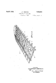
- Fig. 1 is a perspective view of an airplane wing panel in skeleton form
- FIG. 2 is a side elevation of one of the wing r1 s
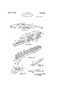
- Fig. 3 is a perspective view of a fragment of a wing beam
- Fig. 4 is a perspective view of a wing drag strut
- Fig. 5 is a sectional detail showing a spacer construction employed in carrying out my invention.
- Fig. 6 is a perspective view of one of the spacer rivets indicated in Figs. 3, 4, and 5.
- the numeral 1 is applied generally to a wing rib formed preferably of metal parts. These ribs are mounted upon and secured in any suitable manner to a frame work made up of front and rear wing beams 2, dra struts 3 and diagonal brace rods 20.
- Eaci of the ribs 1 has a lower chord 4 and an n per chord 21. Intermediate of the ends of tlie rib in a position where the greatest stresses occur, is a vertical strut 22 joining chords 4 and 21, and this vertical strut constitutes the central member of a truss, the side members or upper chord of which areshown at 5 while the lower chord is the chord/4 of the rib.
- the struts 6 stabilize the compression chord 4 by their attachment to tension diagonals 5.
- the struts 6 then stabilize dia onals 5 by their attachment to the tension c 0rd 4.
- Fig. 3 wherein is shown a portion of one of the wing beams 2, 7 and? are channel chord members the flanges of which on either side are joined by diagonal members 8 and 8', also channel-shaped.
- the flanges of the diagonal members are connected together in pairs by means of plates 9 which are secured by rivets 23 in multiple to each flange.
- the diagonal members 8 and 8' are connected directly to the flanges of the channels 7 and 7 by rivets 10, thereby dispensing with the usual gusset plates which must be secured first to the channel flange and then to the web members, thus adding materially to the weight of the beam and to the amount of labor involved in assembling the beam without increasing the strength of the latter.
- I employ at intervalsspacer rivets 11 with reinforcing spacers 12 which are quadruple flanged channels with lips 12 for extending over the edges of the channel chords to prevent their displacement.
- I also employ spacer rivets 11 in the angles between ad acent web members 8 and 8. I also reinforce the channels between diagonal members by somewhat lighter weight channel plates 13 secured in place as by rivets 24. Inspection holes are formed in these plates, and their edges are preferably flanged as shown at 14, to increase their stiffness.
- Fig. 4 I have illustrated, more or less in detail, a hollow beam possessing remarkable rigidity and which I employ as a drag strut will.
- the upper and lower members 15 and 15 of the beam are formed of somewhat lighter gauge material than the quadruple flanged channels 16 and have flanged edges which are riveted to the flanges of the quadruple flanged channels, as shown at 25.
- the members 15 and 15' may be provided with holes 14 having a diameter such as to permit'inspection and to facilitate the application of anti-corrosion material to the interior surfaces whereby the life of aluminum alloy structures can be considerably extended and the danger from accidents caused by failure of metal parts is materially decreased.
- the spacer rivets 11 which are located at right angular intersecting relation to the axis of inspection holes 15 compensate for the metal that was removed when forming the holes and which would otherwise have acted as a local tie between the flanges of the dual flanged members.
- the beam as set forth possesses a materially higher strength-weight ratio and a lower sectional area-rigidity ratio than were heretofore attained in composite members for aircraft structures.
- Spacer rivet 11 may comprise a tubular portion and a rod portion 17 for assembly under the conditions shown in Figs. 3 and 5, or one piece spacer rivets 11 can be used under the conditions shown in Fig. 4.
- a truss structure of high strength-weight ratio comprising a base member, a vertical strut and a diagonal member forming substantially a right angled triangle, a short strut diagonally connecting an intermediate point on the diagonal with an intermediate point on the base member, and an upper chord member supported by said truss structure at the top of said triangle.
- a truss structure of high strength-weight ratio comprising a lower chord and a pair of inclined members, a strut substantially perpendicular to said lower chord connecting the lower chord with the point of juncture between the inclined members, and a pair of short struts diagonally connecting intermediate points of the inclined members with points of the lower chord spaced from said first named strut.
- a truss structure of high strength-weight ratio comprising a vertical strut at substantially the position of greatest stress in the rib, a pair of inclined members extending downwardly at reversed angles from the upper end'of said strut, a lower chord member extending laterally both ways from the lower end of said strut to a point of juncture with said inclined chord members, and a pair of auxiliary struts diagonally connecting at angles other than right angles two intermediate points on said inclined side members with two points 100 on said lower chord member spaced from said vertical strut.
- a wing rib for airplanes an upper chord member and a lower chord member, a perpendicular strut joining said chord mem- 105 bers, an inclined member extending from the upper end of said strut to said lower chord member, and a short diagonal strut connecting an intermediate point on said inclined member with a point on the lower chord member intermediate the lower ends of said strut and inclined member.
- a truss structure comprising a base member; a verticalstrut and a diagonal member forming sub- 115 stantially a right angled triangle; a short strut connecting an intermediate point on the diagonal member with an intermediate point on the base member, said short strut forming I an included angle substantially less than 90 120 in relation to said base member and to said diagonal member; and an upper chord member supported by said truss structure at the top of said trian le.
- a truss struc- 125 ture of high strength-weight ratio comprising a base member; vertical struts; diagonal tie members forming substantially right angle triangles in relation to said vertical struts; short struts connecting intermediate points on said ties to intermediate points on said base members thereby forming included angles of less than 90; and an upper chord member supported by said truss structure atthe top of said triangles.
- a built up drag strut of high strength to weight ratio and low cross sectional area to rigidity ratio comprising a pair of quadruple flanged channel members arranged back to back and spaced apart; riveted s acers for attaching said quadruple flanged c annel members at their webs in said spaced apart relation; a pair of'flat webbed dual flanged channel members arranged back to back with their flanges between and fastened to the remote flanges of said quadruple flanged channel members.
- an upper chord member and a lower chord member each having two side flanges; oppositely disposed diagonal members in laterally paired relation each having two side flanges; said diagonals bridging the space between said chord members, and each end portion of said diagonal abutting and riveted to a flange of said chords; and the middle portions of said paired diagonal member flanges joined by an overlying plate riveted in multiple to each flange.
- a built up drag strut comprising a pair of quadruple flanged mem bers arranged back to back and spaced apart; a pair of dual flanged members arranged back to back and spaced apart with their flanges between and fastened to the outer flanges of said quadruple flanged members; said dual flanged members provided with holes in their webs of a size to facilitate anticorrosion treatment of the interior surfaces of said members; a spacer rivet arranged at a right angular intersecting relation to the axis of the adjacent hole and fastened to the web of each quadruple flanged member.
- a built up drag strut of high strength to weight and low cross sectional area to rigidity ratios comprising a pair of channel mem ers arranged web to web and spaced apart, each of said members comprising two longitudinally flanged edge portions edge joined by a flat web portion paralleling said flanges; riveted spacers connecting said webs in said spaced relation; a pair of longitudinally flanged flat webbed members arranged web to web and spaced apart with their flanges between and joined to the outer flanges of said channel members, said webs having holes of a size to facilitate anti-corrosion treatment of the interior surfaces of said members, and the plane of said holes lying parallel to said spacers.
- a built up drag strut of high strength to weight and low cross sectional area to rigidity ratios comprising a pair of channel members arranged web to web and spaced apart, each of said members comprising two longitudinally flanged edge portions edge joined by a flat web portion paralleling said flanges; riveted spacers connecting said webs in said spaced relation; a pair of longitudinally flanged fiat webbed members arranged web to web and spaced apart with their flanges between and joined to the outer flanges of said channel members, said webs having holes of a size to facilitate anticorrosion treatment of the-interior surfaces of said members, and said spacer rivets arranged at a right angular intersecting relation to the axis of the adjacent hole.
- a structural beam comprising in combination a dual flanged member laterally reinforced by a quadruple flanged spacer comprising side flanges, remote flanges and a web, said remote flanges projecting longitudinally beyond the ends of said side flanges and said web; the ends of said web and said side flanges of said spacer located between and in end-to-side contact with the flanges of said dual flanged member, and the projecting portion of said spacer overlying the flanges of said dual flanged member in side-to-edge relation; a spacer rivet longitudinally located between said side flanges of said spacer and laterally located in retaining relation to said dual flanges and to said spacer.
Description
April 5, 1932.
L. c. MILBURN 1,852,622
AIRPLANE WING STRUCTURE Filesi June 9, 1927 2 Sheets-Sheet 1 lN\ ENTOR Lessi terCJl/ilhu'n AT TORNEY AIRPLANE WING STRUCTURE Filed June 9, 1927 2 Sheets-Sheet 2 )NVENTOR Lessiter 7am m a w ATTORNEY Patented Apr. 5, 1932 UNITED STATES PATENT OFFICE LESSI'I'ER C. MILBURN, OF CLEVELAND, OHIO, ASSIGNOR TO THE GLENN L. MARTIN COMPANY, OF CLEVELAND, OHIO, A CORPORATION OF OHIO AIRPLANE WING STRUCTURE Application filed June 9, 1927. Serial No. 197,532.
This invention relates to improvements in airplanes, more particularly airplanes emplo ing metal structural members.
ere metal structural members have been used in airplane framing a light weight material known as duralumin has been employed toa considerable extent. This material has important advantages, but it is open to the objection that'it deteriorates readily under atmospheric and moisture conditions and,
consequently, should be periodically inspected for defective spots and such spots painted or otherwise treated. Ins 'ection and treatment of open columns or uilt up beams is readily accomplished, but the inspection and treatment of the interior surfaces of closed or substantially closed sections has heretofore been impossible, and, consequently, failures have occurred in parts which, to all 90 external appearances, were in perfect condition.
One of the objects of my invention, therefore, is to provide for the inspection and treatment of internal surfaces of built up metal columns or beams, and to compensate for local weakening due to removal of web metal when forming inspection holes- Another object of the invention is to provide an improved truss construction for airplane ribs whereby the crippling lengths of the heavily stressed chord, andweb members may be reduced for inverted as well as for ordinary flight.
A further object is the provision of means for eliminating gusset plates in built up beam constructions, thereby reducing the weight of the-beam and the number ofcrivets. which must be placed.
Another object of the invention is the provision of an improved built up structure for a drag strut, that is a wing reinforcement running parallel to the wing ribs.
Other-objects and objects relating to details of construction and economies of manufact-are, will appear as I proceed with the description of those embodiments of the invention which,- for the purposes of the present application, I have illustrated in the ac- U companying drawings in which: i
Fig. 1 is a perspective view of an airplane wing panel in skeleton form;
bFig. 2 is a side elevation of one of the wing r1 s;
Fig. 3 is a perspective view of a fragment of a wing beam;
Fig. 4 is a perspective view of a wing drag strut;
Fig. 5 is a sectional detail showing a spacer construction employed in carrying out my invention. Y
Fig. 6 is a perspective view of one of the spacer rivets indicated in Figs. 3, 4, and 5.
Similar reference characters refer to like parts throughout the views.
In the drawings, the numeral 1 is applied generally to a wing rib formed preferably of metal parts. These ribs are mounted upon and secured in any suitable manner to a frame work made up of front and rear wing beams 2, dra struts 3 and diagonal brace rods 20.
Eaci of the ribs 1 has a lower chord 4 and an n per chord 21. Intermediate of the ends of tlie rib in a position where the greatest stresses occur, is a vertical strut 22 joining chords 4 and 21, and this vertical strut constitutes the central member of a truss, the side members or upper chord of which areshown at 5 while the lower chord is the chord/4 of the rib. I add short struts 6 inclined at about the same angle to both of the chords 4 and 5 and disposed somewhere near halfway between the strut 22 and the points of connection between thechords 4 and 5. When the plane is in normal flight, the struts 6 stabilize the compression chord 4 by their attachment to tension diagonals 5. When the plane is in inverted flight and the diagrams 5 become compression members, the struts 6 then stabilize dia onals 5 by their attachment to the tension c 0rd 4.
Referring now to Fig. 3, wherein is shown a portion of one of the wing beams 2, 7 and? are channel chord members the flanges of which on either side are joined by diagonal members 8 and 8', also channel-shaped. The flanges of the diagonal members are connected together in pairs by means of plates 9 which are secured by rivets 23 in multiple to each flange.
The diagonal members 8 and 8' are connected directly to the flanges of the channels 7 and 7 by rivets 10, thereby dispensing with the usual gusset plates which must be secured first to the channel flange and then to the web members, thus adding materially to the weight of the beam and to the amount of labor involved in assembling the beam without increasing the strength of the latter. In order to prevent buckling of the flanges of the channels, the flanges being of considerablewidth in order to accommodate a sufficient number of rivets, I employ at intervalsspacer rivets 11 with reinforcing spacers 12 which are quadruple flanged channels with lips 12 for extending over the edges of the channel chords to prevent their displacement. I also employ spacer rivets 11 in the angles between ad acent web members 8 and 8. I also reinforce the channels between diagonal members by somewhat lighter weight channel plates 13 secured in place as by rivets 24. Inspection holes are formed in these plates, and their edges are preferably flanged as shown at 14, to increase their stiffness.
In Fig. 4 I have illustrated, more or less in detail, a hollow beam possessing remarkable rigidity and which I employ as a drag strut will.
for a wing panel, but which is capable of other uses in airplanes. It consists of a pair of quadruple flanged channels 16 arranged back to back and separated by spacer rivets 11, headed over at endportion 17, that are employed to hold the flanged channels in fixed relation to each other. The upper and lower members 15 and 15 of the beam are formed of somewhat lighter gauge material than the quadruple flanged channels 16 and have flanged edges which are riveted to the flanges of the quadruple flanged channels, as shown at 25. At regular intervals the members 15 and 15' may be provided with holes 14 having a diameter such as to permit'inspection and to facilitate the application of anti-corrosion material to the interior surfaces whereby the life of aluminum alloy structures can be considerably extended and the danger from accidents caused by failure of metal parts is materially decreased.
The spacer rivets 11 which are located at right angular intersecting relation to the axis of inspection holes 15 compensate for the metal that was removed when forming the holes and which would otherwise have acted as a local tie between the flanges of the dual flanged members. The beam as set forth possesses a materially higher strength-weight ratio and a lower sectional area-rigidity ratio than were heretofore attained in composite members for aircraft structures.
Having thus described my invention, I claim:
1. In a wing rib for airplanes, a truss structure of high strength-weight ratio comprising a base member, a vertical strut and a diagonal member forming substantially a right angled triangle, a short strut diagonally connecting an intermediate point on the diagonal with an intermediate point on the base member, and an upper chord member supported by said truss structure at the top of said triangle.
2. In a wing rib for airplanes, a truss structure of high strength-weight ratio'comprising a lower chord and a pair of inclined members, a strut substantially perpendicular to said lower chord connecting the lower chord with the point of juncture between the inclined members, and a pair of short struts diagonally connecting intermediate points of the inclined members with points of the lower chord spaced from said first named strut.
3. In a wing rib for airplanes, a truss structure of high strength-weight ratio comprising a vertical strut at substantially the position of greatest stress in the rib, a pair of inclined members extending downwardly at reversed angles from the upper end'of said strut, a lower chord member extending laterally both ways from the lower end of said strut to a point of juncture with said inclined chord members, and a pair of auxiliary struts diagonally connecting at angles other than right angles two intermediate points on said inclined side members with two points 100 on said lower chord member spaced from said vertical strut.
4. In a wing rib for airplanes, an upper chord member and a lower chord member, a perpendicular strut joining said chord mem- 105 bers, an inclined member extending from the upper end of said strut to said lower chord member, and a short diagonal strut connecting an intermediate point on said inclined member with a point on the lower chord member intermediate the lower ends of said strut and inclined member.
5. In a wing rib for airplanes, a truss structure comprising a base member; a verticalstrut and a diagonal member forming sub- 115 stantially a right angled triangle; a short strut connecting an intermediate point on the diagonal member with an intermediate point on the base member, said short strut forming I an included angle substantially less than 90 120 in relation to said base member and to said diagonal member; and an upper chord member supported by said truss structure at the top of said trian le.
6. In a wing ri for airplanes, a truss struc- 125 ture of high strength-weight ratio and comprising a base member; vertical struts; diagonal tie members forming substantially right angle triangles in relation to said vertical struts; short struts connecting intermediate points on said ties to intermediate points on said base members thereby forming included angles of less than 90; and an upper chord member supported by said truss structure atthe top of said triangles.
7. In an airplane, a built up drag strut of high strength to weight ratio and low cross sectional area to rigidity ratio comprising a pair of quadruple flanged channel members arranged back to back and spaced apart; riveted s acers for attaching said quadruple flanged c annel members at their webs in said spaced apart relation; a pair of'flat webbed dual flanged channel members arranged back to back with their flanges between and fastened to the remote flanges of said quadruple flanged channel members.
8. In a metal beam construction for airplanes, an upper chord member and a lower chord member each having two side flanges; oppositely disposed diagonal members in laterally paired relation each having two side flanges; said diagonals bridging the space between said chord members, and each end portion of said diagonal abutting and riveted to a flange of said chords; and the middle portions of said paired diagonal member flanges joined by an overlying plate riveted in multiple to each flange.
'9. In an airplane, a built up drag strut comprising a pair of quadruple flanged mem bers arranged back to back and spaced apart; a pair of dual flanged members arranged back to back and spaced apart with their flanges between and fastened to the outer flanges of said quadruple flanged members; said dual flanged members provided with holes in their webs of a size to facilitate anticorrosion treatment of the interior surfaces of said members; a spacer rivet arranged at a right angular intersecting relation to the axis of the adjacent hole and fastened to the web of each quadruple flanged member.-
10. In an airplane, a built up drag strut of high strength to weight and low cross sectional area to rigidity ratios comprising a pair of channel mem ers arranged web to web and spaced apart, each of said members comprising two longitudinally flanged edge portions edge joined by a flat web portion paralleling said flanges; riveted spacers connecting said webs in said spaced relation; a pair of longitudinally flanged flat webbed members arranged web to web and spaced apart with their flanges between and joined to the outer flanges of said channel members, said webs having holes of a size to facilitate anti-corrosion treatment of the interior surfaces of said members, and the plane of said holes lying parallel to said spacers.
11. In an airplane, a built up drag strut of high strength to weight and low cross sectional area to rigidity ratios comprising a pair of channel members arranged web to web and spaced apart, each of said members comprising two longitudinally flanged edge portions edge joined by a flat web portion paralleling said flanges; riveted spacers connecting said webs in said spaced relation; a pair of longitudinally flanged fiat webbed members arranged web to web and spaced apart with their flanges between and joined to the outer flanges of said channel members, said webs having holes of a size to facilitate anticorrosion treatment of the-interior surfaces of said members, and said spacer rivets arranged at a right angular intersecting relation to the axis of the adjacent hole.
12. A structural beam comprising in combination a dual flanged member laterally reinforced by a quadruple flanged spacer comprising side flanges, remote flanges and a web, said remote flanges projecting longitudinally beyond the ends of said side flanges and said web; the ends of said web and said side flanges of said spacer located between and in end-to-side contact with the flanges of said dual flanged member, and the projecting portion of said spacer overlying the flanges of said dual flanged member in side-to-edge relation; a spacer rivet longitudinally located between said side flanges of said spacer and laterally located in retaining relation to said dual flanges and to said spacer.
In testimony whereof, I hereunto afiix my signature.
LESSITER C. MILBURN.
Priority Applications (1)
| Application Number | Priority Date | Filing Date | Title |
|---|---|---|---|
| US197532A US1852622A (en) | 1927-06-09 | 1927-06-09 | Airplane wing structure |
Applications Claiming Priority (1)
| Application Number | Priority Date | Filing Date | Title |
|---|---|---|---|
| US197532A US1852622A (en) | 1927-06-09 | 1927-06-09 | Airplane wing structure |
Publications (1)
| Publication Number | Publication Date |
|---|---|
| US1852622A true US1852622A (en) | 1932-04-05 |
Family
ID=22729783
Family Applications (1)
| Application Number | Title | Priority Date | Filing Date |
|---|---|---|---|
| US197532A Expired - Lifetime US1852622A (en) | 1927-06-09 | 1927-06-09 | Airplane wing structure |
Country Status (1)
| Country | Link |
|---|---|
| US (1) | US1852622A (en) |
Cited By (10)
| Publication number | Priority date | Publication date | Assignee | Title |
|---|---|---|---|---|
| US4646505A (en) * | 1983-07-19 | 1987-03-03 | Sadelmi Cogepi S.p.A. | Structural element |
| US20070217918A1 (en) * | 2006-03-20 | 2007-09-20 | Baker Myles L | Lightweight composite truss wind turbine blade |
| US20100290890A1 (en) * | 2007-10-04 | 2010-11-18 | Bronswerk Heat Transfer B.V. | Fan |
| US20120321479A1 (en) * | 2010-02-12 | 2012-12-20 | Thomas Bruun | Method for production of a rotor blade for a wind turbine generator and a rotor blade |
| US20130064677A1 (en) * | 2011-09-13 | 2013-03-14 | General Electric Company | Rotor blade assembly for wind turbine |
| JP2013519019A (en) * | 2010-02-08 | 2013-05-23 | 国能風力発電有限公司 | Structure of blades for wind wheels of vertical axis wind power generator |
| US8475133B2 (en) | 2008-12-05 | 2013-07-02 | Modular Wind Energy, Inc. | Efficient wind turbine blades, wind turbine blade structures, and associated systems and methods of manufacture, assembly and use |
| US20130309095A1 (en) * | 2012-05-17 | 2013-11-21 | SkyWolf Wind Turbine Corp. | Wind turbine blade having improved structural and aerodynamic characteristics |
| US9500179B2 (en) | 2010-05-24 | 2016-11-22 | Vestas Wind Systems A/S | Segmented wind turbine blades with truss connection regions, and associated systems and methods |
| CN110905719A (en) * | 2019-12-02 | 2020-03-24 | 三一重能有限公司 | Wind power blade and wind power generation equipment |
-
1927
- 1927-06-09 US US197532A patent/US1852622A/en not_active Expired - Lifetime
Cited By (21)
| Publication number | Priority date | Publication date | Assignee | Title |
|---|---|---|---|---|
| US4646505A (en) * | 1983-07-19 | 1987-03-03 | Sadelmi Cogepi S.p.A. | Structural element |
| US7891948B2 (en) | 2006-03-20 | 2011-02-22 | Modular Wind Energy, Inc. | Lightweight composite truss wind turbine blade |
| US20070217918A1 (en) * | 2006-03-20 | 2007-09-20 | Baker Myles L | Lightweight composite truss wind turbine blade |
| US7891949B2 (en) | 2006-03-20 | 2011-02-22 | Modular Wind Energy, Inc. | Lightweight composite truss wind turbine blade |
| US7517198B2 (en) * | 2006-03-20 | 2009-04-14 | Modular Wind Energy, Inc. | Lightweight composite truss wind turbine blade |
| US20090191063A1 (en) * | 2006-03-20 | 2009-07-30 | Baker Myles L | Lightweight composite truss wind turbine blade |
| US7891950B2 (en) | 2006-03-20 | 2011-02-22 | Modular Wind Energy, Inc. | Lightweight composite truss wind turbine blade |
| EP2134963A1 (en) * | 2007-03-20 | 2009-12-23 | Myles L. Baker | Lightweight composite truss wind turbine blade |
| JP2010522307A (en) * | 2007-03-20 | 2010-07-01 | モジュラー ウィンド エナジー インコーポレイテッド | Lightweight composite truss wind turbine blade |
| WO2008115265A1 (en) * | 2007-03-20 | 2008-09-25 | Modular Wind Energy, Inc. | Lightweight composite truss wind turbine blade |
| EP2134963A4 (en) * | 2007-03-20 | 2013-02-27 | Modular Wind Energy Inc | Lightweight composite truss wind turbine blade |
| US20100290890A1 (en) * | 2007-10-04 | 2010-11-18 | Bronswerk Heat Transfer B.V. | Fan |
| US8961109B2 (en) * | 2007-10-04 | 2015-02-24 | Bronswerk Heat Transfer B.V. | Fan |
| US8480370B2 (en) | 2008-12-05 | 2013-07-09 | Modular Wind Energy, Inc. | Efficient wind turbine blades, wind turbine blade structures, and associated systems and methods of manufacture, assembly and use |
| US8475133B2 (en) | 2008-12-05 | 2013-07-02 | Modular Wind Energy, Inc. | Efficient wind turbine blades, wind turbine blade structures, and associated systems and methods of manufacture, assembly and use |
| JP2013519019A (en) * | 2010-02-08 | 2013-05-23 | 国能風力発電有限公司 | Structure of blades for wind wheels of vertical axis wind power generator |
| US20120321479A1 (en) * | 2010-02-12 | 2012-12-20 | Thomas Bruun | Method for production of a rotor blade for a wind turbine generator and a rotor blade |
| US9500179B2 (en) | 2010-05-24 | 2016-11-22 | Vestas Wind Systems A/S | Segmented wind turbine blades with truss connection regions, and associated systems and methods |
| US20130064677A1 (en) * | 2011-09-13 | 2013-03-14 | General Electric Company | Rotor blade assembly for wind turbine |
| US20130309095A1 (en) * | 2012-05-17 | 2013-11-21 | SkyWolf Wind Turbine Corp. | Wind turbine blade having improved structural and aerodynamic characteristics |
| CN110905719A (en) * | 2019-12-02 | 2020-03-24 | 三一重能有限公司 | Wind power blade and wind power generation equipment |
Similar Documents
| Publication | Publication Date | Title |
|---|---|---|
| US1924881A (en) | Open truss girder | |
| US3103025A (en) | Structural unit | |
| US1852622A (en) | Airplane wing structure | |
| US1994716A (en) | Girder | |
| US1924880A (en) | Open truss girder | |
| US1792489A (en) | Joint fitting | |
| US1799337A (en) | Building unit | |
| US1523106A (en) | Sheet-metal girder | |
| US1545129A (en) | Aircraft structure | |
| US1887627A (en) | Method and means of fabricating structures of metal and nonmetallic materials | |
| US1881296A (en) | Metal built aircraft | |
| US2347542A (en) | Girder for aircraft structure | |
| US1431520A (en) | Aeroplane | |
| US2405917A (en) | Strut element and joint | |
| US1619372A (en) | Wing construction for metal airplanes | |
| US1914344A (en) | Sheet metal joint construction | |
| US2407480A (en) | Aircraft fuselage and wing construction | |
| US2395205A (en) | Aircraft structure | |
| US1643577A (en) | Hollow light-metal girder | |
| US11772781B2 (en) | Aircraft including a reinforced main landing gear box | |
| US1840901A (en) | Airplane | |
| US2014801A (en) | Rib construction | |
| US1854330A (en) | Metallic construction of aircraft | |
| US1827181A (en) | Aeroplane construction | |
| US2384409A (en) | Airfoil structure for aircraft |