EP3214267A1 - Riblets for a flowpath surface of a turbomachine - Google Patents
Riblets for a flowpath surface of a turbomachine Download PDFInfo
- Publication number
- EP3214267A1 EP3214267A1 EP17155413.2A EP17155413A EP3214267A1 EP 3214267 A1 EP3214267 A1 EP 3214267A1 EP 17155413 A EP17155413 A EP 17155413A EP 3214267 A1 EP3214267 A1 EP 3214267A1
- Authority
- EP
- European Patent Office
- Prior art keywords
- riblets
- component
- section
- flowpath
- flowpath surface
- Prior art date
- Legal status (The legal status is an assumption and is not a legal conclusion. Google has not performed a legal analysis and makes no representation as to the accuracy of the status listed.)
- Withdrawn
Links
Images


Classifications
-
- F—MECHANICAL ENGINEERING; LIGHTING; HEATING; WEAPONS; BLASTING
- F01—MACHINES OR ENGINES IN GENERAL; ENGINE PLANTS IN GENERAL; STEAM ENGINES
- F01D—NON-POSITIVE DISPLACEMENT MACHINES OR ENGINES, e.g. STEAM TURBINES
- F01D5/00—Blades; Blade-carrying members; Heating, heat-insulating, cooling or antivibration means on the blades or the members
- F01D5/12—Blades
- F01D5/14—Form or construction
- F01D5/141—Shape, i.e. outer, aerodynamic form
- F01D5/142—Shape, i.e. outer, aerodynamic form of the blades of successive rotor or stator blade-rows
- F01D5/143—Contour of the outer or inner working fluid flow path wall, i.e. shroud or hub contour
-
- F—MECHANICAL ENGINEERING; LIGHTING; HEATING; WEAPONS; BLASTING
- F01—MACHINES OR ENGINES IN GENERAL; ENGINE PLANTS IN GENERAL; STEAM ENGINES
- F01D—NON-POSITIVE DISPLACEMENT MACHINES OR ENGINES, e.g. STEAM TURBINES
- F01D5/00—Blades; Blade-carrying members; Heating, heat-insulating, cooling or antivibration means on the blades or the members
- F01D5/12—Blades
- F01D5/14—Form or construction
- F01D5/141—Shape, i.e. outer, aerodynamic form
- F01D5/145—Means for influencing boundary layers or secondary circulations
-
- F—MECHANICAL ENGINEERING; LIGHTING; HEATING; WEAPONS; BLASTING
- F01—MACHINES OR ENGINES IN GENERAL; ENGINE PLANTS IN GENERAL; STEAM ENGINES
- F01D—NON-POSITIVE DISPLACEMENT MACHINES OR ENGINES, e.g. STEAM TURBINES
- F01D5/00—Blades; Blade-carrying members; Heating, heat-insulating, cooling or antivibration means on the blades or the members
- F01D5/12—Blades
- F01D5/14—Form or construction
- F01D5/141—Shape, i.e. outer, aerodynamic form
-
- F—MECHANICAL ENGINEERING; LIGHTING; HEATING; WEAPONS; BLASTING
- F01—MACHINES OR ENGINES IN GENERAL; ENGINE PLANTS IN GENERAL; STEAM ENGINES
- F01D—NON-POSITIVE DISPLACEMENT MACHINES OR ENGINES, e.g. STEAM TURBINES
- F01D9/00—Stators
- F01D9/02—Nozzles; Nozzle boxes; Stator blades; Guide conduits, e.g. individual nozzles
- F01D9/04—Nozzles; Nozzle boxes; Stator blades; Guide conduits, e.g. individual nozzles forming ring or sector
- F01D9/041—Nozzles; Nozzle boxes; Stator blades; Guide conduits, e.g. individual nozzles forming ring or sector using blades
-
- F—MECHANICAL ENGINEERING; LIGHTING; HEATING; WEAPONS; BLASTING
- F04—POSITIVE - DISPLACEMENT MACHINES FOR LIQUIDS; PUMPS FOR LIQUIDS OR ELASTIC FLUIDS
- F04D—NON-POSITIVE-DISPLACEMENT PUMPS
- F04D29/00—Details, component parts, or accessories
- F04D29/26—Rotors specially for elastic fluids
- F04D29/32—Rotors specially for elastic fluids for axial flow pumps
- F04D29/321—Rotors specially for elastic fluids for axial flow pumps for axial flow compressors
- F04D29/324—Blades
-
- F—MECHANICAL ENGINEERING; LIGHTING; HEATING; WEAPONS; BLASTING
- F04—POSITIVE - DISPLACEMENT MACHINES FOR LIQUIDS; PUMPS FOR LIQUIDS OR ELASTIC FLUIDS
- F04D—NON-POSITIVE-DISPLACEMENT PUMPS
- F04D29/00—Details, component parts, or accessories
- F04D29/40—Casings; Connections of working fluid
- F04D29/52—Casings; Connections of working fluid for axial pumps
- F04D29/54—Fluid-guiding means, e.g. diffusers
- F04D29/541—Specially adapted for elastic fluid pumps
- F04D29/542—Bladed diffusers
-
- F—MECHANICAL ENGINEERING; LIGHTING; HEATING; WEAPONS; BLASTING
- F04—POSITIVE - DISPLACEMENT MACHINES FOR LIQUIDS; PUMPS FOR LIQUIDS OR ELASTIC FLUIDS
- F04D—NON-POSITIVE-DISPLACEMENT PUMPS
- F04D29/00—Details, component parts, or accessories
- F04D29/66—Combating cavitation, whirls, noise, vibration or the like; Balancing
- F04D29/68—Combating cavitation, whirls, noise, vibration or the like; Balancing by influencing boundary layers
- F04D29/681—Combating cavitation, whirls, noise, vibration or the like; Balancing by influencing boundary layers especially adapted for elastic fluid pumps
-
- F—MECHANICAL ENGINEERING; LIGHTING; HEATING; WEAPONS; BLASTING
- F15—FLUID-PRESSURE ACTUATORS; HYDRAULICS OR PNEUMATICS IN GENERAL
- F15D—FLUID DYNAMICS, i.e. METHODS OR MEANS FOR INFLUENCING THE FLOW OF GASES OR LIQUIDS
- F15D1/00—Influencing flow of fluids
- F15D1/002—Influencing flow of fluids by influencing the boundary layer
- F15D1/0025—Influencing flow of fluids by influencing the boundary layer using passive means, i.e. without external energy supply
- F15D1/003—Influencing flow of fluids by influencing the boundary layer using passive means, i.e. without external energy supply comprising surface features, e.g. indentations or protrusions
- F15D1/0035—Influencing flow of fluids by influencing the boundary layer using passive means, i.e. without external energy supply comprising surface features, e.g. indentations or protrusions in the form of riblets
- F15D1/004—Influencing flow of fluids by influencing the boundary layer using passive means, i.e. without external energy supply comprising surface features, e.g. indentations or protrusions in the form of riblets oriented essentially parallel to the direction of flow
-
- F—MECHANICAL ENGINEERING; LIGHTING; HEATING; WEAPONS; BLASTING
- F05—INDEXING SCHEMES RELATING TO ENGINES OR PUMPS IN VARIOUS SUBCLASSES OF CLASSES F01-F04
- F05D—INDEXING SCHEME FOR ASPECTS RELATING TO NON-POSITIVE-DISPLACEMENT MACHINES OR ENGINES, GAS-TURBINES OR JET-PROPULSION PLANTS
- F05D2220/00—Application
- F05D2220/30—Application in turbines
- F05D2220/32—Application in turbines in gas turbines
-
- F—MECHANICAL ENGINEERING; LIGHTING; HEATING; WEAPONS; BLASTING
- F05—INDEXING SCHEMES RELATING TO ENGINES OR PUMPS IN VARIOUS SUBCLASSES OF CLASSES F01-F04
- F05D—INDEXING SCHEME FOR ASPECTS RELATING TO NON-POSITIVE-DISPLACEMENT MACHINES OR ENGINES, GAS-TURBINES OR JET-PROPULSION PLANTS
- F05D2230/00—Manufacture
- F05D2230/20—Manufacture essentially without removing material
- F05D2230/21—Manufacture essentially without removing material by casting
-
- F—MECHANICAL ENGINEERING; LIGHTING; HEATING; WEAPONS; BLASTING
- F05—INDEXING SCHEMES RELATING TO ENGINES OR PUMPS IN VARIOUS SUBCLASSES OF CLASSES F01-F04
- F05D—INDEXING SCHEME FOR ASPECTS RELATING TO NON-POSITIVE-DISPLACEMENT MACHINES OR ENGINES, GAS-TURBINES OR JET-PROPULSION PLANTS
- F05D2230/00—Manufacture
- F05D2230/90—Coating; Surface treatment
-
- F—MECHANICAL ENGINEERING; LIGHTING; HEATING; WEAPONS; BLASTING
- F05—INDEXING SCHEMES RELATING TO ENGINES OR PUMPS IN VARIOUS SUBCLASSES OF CLASSES F01-F04
- F05D—INDEXING SCHEME FOR ASPECTS RELATING TO NON-POSITIVE-DISPLACEMENT MACHINES OR ENGINES, GAS-TURBINES OR JET-PROPULSION PLANTS
- F05D2240/00—Components
- F05D2240/10—Stators
- F05D2240/12—Fluid guiding means, e.g. vanes
- F05D2240/128—Nozzles
-
- F—MECHANICAL ENGINEERING; LIGHTING; HEATING; WEAPONS; BLASTING
- F05—INDEXING SCHEMES RELATING TO ENGINES OR PUMPS IN VARIOUS SUBCLASSES OF CLASSES F01-F04
- F05D—INDEXING SCHEME FOR ASPECTS RELATING TO NON-POSITIVE-DISPLACEMENT MACHINES OR ENGINES, GAS-TURBINES OR JET-PROPULSION PLANTS
- F05D2240/00—Components
- F05D2240/20—Rotors
- F05D2240/30—Characteristics of rotor blades, i.e. of any element transforming dynamic fluid energy to or from rotational energy and being attached to a rotor
- F05D2240/31—Characteristics of rotor blades, i.e. of any element transforming dynamic fluid energy to or from rotational energy and being attached to a rotor with roughened surfaces
-
- F—MECHANICAL ENGINEERING; LIGHTING; HEATING; WEAPONS; BLASTING
- F05—INDEXING SCHEMES RELATING TO ENGINES OR PUMPS IN VARIOUS SUBCLASSES OF CLASSES F01-F04
- F05D—INDEXING SCHEME FOR ASPECTS RELATING TO NON-POSITIVE-DISPLACEMENT MACHINES OR ENGINES, GAS-TURBINES OR JET-PROPULSION PLANTS
- F05D2250/00—Geometry
- F05D2250/10—Two-dimensional
- F05D2250/18—Two-dimensional patterned
- F05D2250/181—Two-dimensional patterned ridged
-
- F—MECHANICAL ENGINEERING; LIGHTING; HEATING; WEAPONS; BLASTING
- F05—INDEXING SCHEMES RELATING TO ENGINES OR PUMPS IN VARIOUS SUBCLASSES OF CLASSES F01-F04
- F05D—INDEXING SCHEME FOR ASPECTS RELATING TO NON-POSITIVE-DISPLACEMENT MACHINES OR ENGINES, GAS-TURBINES OR JET-PROPULSION PLANTS
- F05D2250/00—Geometry
- F05D2250/10—Two-dimensional
- F05D2250/18—Two-dimensional patterned
- F05D2250/182—Two-dimensional patterned crenellated, notched
-
- F—MECHANICAL ENGINEERING; LIGHTING; HEATING; WEAPONS; BLASTING
- F05—INDEXING SCHEMES RELATING TO ENGINES OR PUMPS IN VARIOUS SUBCLASSES OF CLASSES F01-F04
- F05D—INDEXING SCHEME FOR ASPECTS RELATING TO NON-POSITIVE-DISPLACEMENT MACHINES OR ENGINES, GAS-TURBINES OR JET-PROPULSION PLANTS
- F05D2250/00—Geometry
- F05D2250/20—Three-dimensional
- F05D2250/29—Three-dimensional machined; miscellaneous
- F05D2250/294—Three-dimensional machined; miscellaneous grooved
-
- F—MECHANICAL ENGINEERING; LIGHTING; HEATING; WEAPONS; BLASTING
- F05—INDEXING SCHEMES RELATING TO ENGINES OR PUMPS IN VARIOUS SUBCLASSES OF CLASSES F01-F04
- F05D—INDEXING SCHEME FOR ASPECTS RELATING TO NON-POSITIVE-DISPLACEMENT MACHINES OR ENGINES, GAS-TURBINES OR JET-PROPULSION PLANTS
- F05D2250/00—Geometry
- F05D2250/60—Structure; Surface texture
- F05D2250/61—Structure; Surface texture corrugated
- F05D2250/611—Structure; Surface texture corrugated undulated
-
- F—MECHANICAL ENGINEERING; LIGHTING; HEATING; WEAPONS; BLASTING
- F05—INDEXING SCHEMES RELATING TO ENGINES OR PUMPS IN VARIOUS SUBCLASSES OF CLASSES F01-F04
- F05D—INDEXING SCHEME FOR ASPECTS RELATING TO NON-POSITIVE-DISPLACEMENT MACHINES OR ENGINES, GAS-TURBINES OR JET-PROPULSION PLANTS
- F05D2250/00—Geometry
- F05D2250/90—Variable geometry
-
- F—MECHANICAL ENGINEERING; LIGHTING; HEATING; WEAPONS; BLASTING
- F05—INDEXING SCHEMES RELATING TO ENGINES OR PUMPS IN VARIOUS SUBCLASSES OF CLASSES F01-F04
- F05D—INDEXING SCHEME FOR ASPECTS RELATING TO NON-POSITIVE-DISPLACEMENT MACHINES OR ENGINES, GAS-TURBINES OR JET-PROPULSION PLANTS
- F05D2260/00—Function
- F05D2260/20—Heat transfer, e.g. cooling
- F05D2260/221—Improvement of heat transfer
- F05D2260/2214—Improvement of heat transfer by increasing the heat transfer surface
- F05D2260/22141—Improvement of heat transfer by increasing the heat transfer surface using fins or ribs
-
- F—MECHANICAL ENGINEERING; LIGHTING; HEATING; WEAPONS; BLASTING
- F05—INDEXING SCHEMES RELATING TO ENGINES OR PUMPS IN VARIOUS SUBCLASSES OF CLASSES F01-F04
- F05D—INDEXING SCHEME FOR ASPECTS RELATING TO NON-POSITIVE-DISPLACEMENT MACHINES OR ENGINES, GAS-TURBINES OR JET-PROPULSION PLANTS
- F05D2270/00—Control
- F05D2270/01—Purpose of the control system
- F05D2270/17—Purpose of the control system to control boundary layer
-
- Y—GENERAL TAGGING OF NEW TECHNOLOGICAL DEVELOPMENTS; GENERAL TAGGING OF CROSS-SECTIONAL TECHNOLOGIES SPANNING OVER SEVERAL SECTIONS OF THE IPC; TECHNICAL SUBJECTS COVERED BY FORMER USPC CROSS-REFERENCE ART COLLECTIONS [XRACs] AND DIGESTS
- Y02—TECHNOLOGIES OR APPLICATIONS FOR MITIGATION OR ADAPTATION AGAINST CLIMATE CHANGE
- Y02T—CLIMATE CHANGE MITIGATION TECHNOLOGIES RELATED TO TRANSPORTATION
- Y02T50/00—Aeronautics or air transport
- Y02T50/60—Efficient propulsion technologies, e.g. for aircraft
Definitions
- the present subject matter relates generally to a flowpath surface of a turbomachine including a plurality of riblets.
- a gas turbine engine generally includes a fan and a core arranged in flow communication with one another. Additionally, the core of the gas turbine engine general includes, in serial flow order, a compressor section, a combustion section, a turbine section, and an exhaust section.
- air is provided from the fan to an inlet of the compressor section where one or more axial compressors progressively compress the air until it reaches the combustion section.
- Fuel is mixed with the compressed air and burned within the combustion section to provide combustion gases.
- the combustion gases are routed from the combustion section to the turbine section.
- the flow of combustion gases through the turbine section drives the turbine section and is then routed through the exhaust section, e.g., to atmosphere.
- the turbine section typically includes a plurality of sequentially arranged stage(s) of turbine nozzles and turbine rotor blades.
- Each of the turbine nozzles within the various stages of turbine nozzles and each of the turbine rotor blades within the various stages of turbine rotor blades include one or more flowpath surfaces.
- riblets i.e., small ribs or fins
- each of the sequential riblets conventionally define a uniform geometry and spacing.
- the riblets may be beneficial given the airflow conditions at a first flowpath surface, while the riblets may actually provide detrimental effects given the airflow conditions at a second flowpath surface.
- the inventor of the present disclosure has discovered that it may be beneficial to customize the plurality of riblets to a specific location within the gas turbine engine at which the flowpath surface is located. More specifically, a flowpath surface for a gas turbine engine having a plurality of riblets customized to the specific location within the gas turbine engine would be particularly beneficial.
- a component stage for a turbomachine defining a core air flowpath includes a component section.
- the component section includes a flowpath surface at least partially exposed to the core air flowpath and further comprising a plurality of sequentially arranged riblets on the flowpath surface.
- the plurality of sequentially arranged riblets define one or both of a non-uniform geometry or a non-uniform spacing.
- a turbomachine in another exemplary embodiment of the present disclosure, includes a compressor section, and a turbine section in serial flow order and defining at least in part a core air flowpath.
- One of the compressor section or the turbine section includes a component stage.
- the component stage includes a component section.
- the component section includes a flowpath surface at least partially exposed to the core air flowpath and further including a plurality of sequentially arranged riblets on the flowpath surface.
- the plurality of sequentially arranged riblets define one or both of a non-uniform geometry or a non-uniform spacing.
- a method of forming a component section of a component stage for a compressor section or a turbine section of a turbomachine defines a core air flowpath.
- the method includes forming a base geometry of the component section.
- the base geometry includes a flowpath surface to be at least partially exposed to the core air flowpath.
- the method also includes forming a plurality of riblets on the flowpath surface of the base geometry of the component section using an additive manufacturing process, the plurality of riblets arranged sequentially and defining one or both of a non-uniform geometry or a non-uniform spacing.
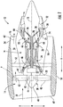
- FIG. 1 is a schematic cross-sectional view of a turbomachine in accordance with an exemplary embodiment of the present disclosure. More particularly, for the embodiment of FIG. 1 , the turbomachine is configured as a gas turbine engine, or rather as a high-bypass turbofan jet engine 12, referred to herein as "turbofan engine 12." As shown in FIG. 1 , the turbofan engine 12 defines an axial direction A (extending parallel to a longitudinal centerline 13 provided for reference), a radial direction R, and a circumferential direction (not shown) extending about the axial direction A. In general, the turbofan 12 includes a fan section 14 and a core turbine engine 16 disposed downstream from the fan section 14.
- the exemplary core turbine engine 16 depicted generally includes a substantially tubular outer casing 18 that defines an annular inlet 20.
- the outer casing 18 encases and the core turbine engine 16 includes, in serial flow relationship, a compressor section including a booster or low pressure (LP) compressor 22 and a high pressure (HP) compressor 24; a combustion section 26; a turbine section including a high pressure (HP) turbine 28 and a low pressure (LP) turbine 30; and a jet exhaust nozzle section 32.
- a high pressure (HP) shaft or spool 34 drivingly connects the HP turbine 28 to the HP compressor 24.
- a low pressure (LP) shaft or spool 36 drivingly connects the LP turbine 30 to the LP compressor 22. Accordingly, the LP shaft 36 and HP shaft 34 are each rotary components, rotating about the axial direction A during operation of the turbofan engine 12.
- the fan section 14 includes a variable pitch fan 38 having a plurality of fan blades 40 coupled to a disk 42 in a spaced apart manner. As depicted, the fan blades 40 extend outwardly from disk 42 generally along the radial direction R. Each fan blade 40 is rotatable relative to the disk 42 about a pitch axis P by virtue of the fan blades 40 being operatively coupled to a suitable pitch change mechanism 44 configured to collectively vary the pitch of the fan blades 40 in unison.
- the fan blades 40, disk 42, and pitch change mechanism 44 are together rotatable about the longitudinal axis 12 by LP shaft 36 across a power gear box 46.
- the power gear box 46 includes a plurality of gears for adjusting the rotational speed of the fan 38 relative to the LP shaft 36 to a more efficient rotational fan speed. More particularly, the fan section includes a fan shaft rotatable by the LP shaft 36 across the power gearbox 46. Accordingly, the fan shaft may also be considered a rotary component, and is similarly supported by one or more bearings.
- the disk 42 is covered by a rotatable front hub 48 aerodynamically contoured to promote an airflow through the plurality of fan blades 40.
- the exemplary fan section 14 includes an annular fan casing or outer nacelle 50 that circumferentially surrounds the fan 38 and/or at least a portion of the core turbine engine 16.
- the exemplary nacelle 50 is supported relative to the core turbine engine 16 by a plurality of circumferentially-spaced outlet guide vanes 52.
- a downstream section 54 of the nacelle 50 extends over an outer portion of the core turbine engine 16 so as to define a bypass airflow passage 56 therebetween.
- a volume of air 58 enters the turbofan 10 through an associated inlet 60 of the nacelle 50 and/or fan section 14.
- a first portion of the air 58 as indicated by arrows 62 is directed or routed into the bypass airflow passage 56 and a second portion of the air 58 as indicated by arrow 64 is directed or routed into the core air flowpath 37, or more specifically into the LP compressor 22.
- the ratio between the first portion of air 62 and the second portion of air 64 is commonly known as a bypass ratio.
- the pressure of the second portion of air 64 is then increased as it is routed through the high pressure (HP) compressor 24 and into the combustion section 26, where it is mixed with fuel and burned to provide combustion gases 66.
- HP high pressure
- the combustion gases 66 are routed through the HP turbine 28 where a portion of thermal and/or kinetic energy from the combustion gases 66 is extracted via sequential stages of HP turbine stator vanes 68 that are coupled to the outer casing 18 and HP turbine rotor blades 70 that are coupled to the HP shaft or spool 34, thus causing the HP shaft or spool 34 to rotate, thereby supporting operation of the HP compressor 24.
- the combustion gases 66 are then routed through the LP turbine 30 where a second portion of thermal and kinetic energy is extracted from the combustion gases 66 via sequential stages of LP turbine stator vanes 72 that are coupled to the outer casing 18 and LP turbine rotor blades 74 that are coupled to the LP shaft or spool 36, thus causing the LP shaft or spool 36 to rotate, thereby supporting operation of the LP compressor 22 and/or rotation of the fan 38.
- the combustion gases 66 are subsequently routed through the jet exhaust nozzle section 32 of the core turbine engine 16 to provide propulsive thrust. Simultaneously, the pressure of the first portion of air 62 is substantially increased as the first portion of air 62 is routed through the bypass airflow passage 56 before it is exhausted from a fan nozzle exhaust section 76 of the turbofan 10, also providing propulsive thrust.
- the HP turbine 28, the LP turbine 30, and the jet exhaust nozzle section 32 at least partially define a hot gas path 78 for routing the combustion gases 66 through the core turbine engine 16.
- turbofan engine 12 depicted in FIG. 1 is provided by way of example only, and that in other exemplary embodiments, the turbofan engine 12 may have any other suitable configuration.
- aspects of the present disclosure may be incorporated into any other suitable gas turbine engine.
- aspects of the present disclosure may be incorporated into, e.g., a turboprop engine, a turboshaft engine, or a turbojet engine.
- aspects of the present disclosure may be incorporated into any other suitable turbomachine, including, without limitation, a steam turbine, a centrifugal compressor, and/or a turbocharger.
- the combustion section 26 depicted generally includes a combustor 79 having a combustion chamber 80 defined by an inner liner 82 and an outer liner 84, the combustion chamber 80 extending generally along the axial direction A from a forward end 86 to an aft end 88.
- a plurality of fuel nozzles 90 are positioned at the forward end 86 of the combustion chamber 80 for providing the combustion chamber 80 with a mixture of fuel and compressed air from the compressor section. As discussed above, the fuel and air mixture is combusted within the combustion chamber 80 to generate a flow of combustion gasses therethrough.
- the HP turbine 28 Downstream of the combustion section 26, the HP turbine 28 includes a plurality of turbine component stages, each turbine component stage comprising a plurality of turbine component sections. More particularly, for the embodiment depicted, the HP turbine 28 includes a plurality of turbine nozzle stages, as well as one or more stages of turbine rotor blades. Specifically, for the embodiment depicted, the HP turbine 28 includes a first turbine nozzle stage 92 and a second turbine nozzle stage 94, each configured to direct a flow of combustion gasses therethrough.
- the first turbine nozzle stage 92 includes a plurality of turbine nozzle sections 96 spaced along a circumferential direction C (a direction extending about the axial direction A; see FIG. 3 ).
- the first turbine nozzle stage 92 is located immediately downstream from the combustion section 26, and thus may also be referred to as a combustor discharge nozzle stage having a plurality of combustion discharge nozzle sections.
- the second turbine nozzle stage 94 also includes a plurality of turbine nozzle sections 98 spaced along the circumferential direction C.
- Each of the turbine nozzle sections 96, 98 forming the first and second turbine nozzle stages 92, 94 includes a turbine nozzle 100 positioned within the core air flowpath 37 and an endwall at least partially exposed to (and at least partially defining) the core air flowpath 37. More particularly, each nozzle section 96, 98 includes an inner endwall 102 and an outer endwall 104, with the nozzle 100 extending generally along the radial direction R from the inner endwall 102 to the outer endwall 104.
- the turbine nozzle 100, inner endwall 102, and outer endwall 104 each include a flowpath surface 106 at least partially exposed to the core air flowpath 37.
- the HP turbine 28 Located immediately downstream of the first turbine nozzle stage 92 and immediately upstream of the second turbine nozzle stage 94, the HP turbine 28 includes a first turbine rotor blade stage 108.
- the first turbine rotor blades stage 108 includes a plurality of turbine rotor blade sections 110 spaced along the circumferential direction C and a first stage rotor disk 112.
- the plurality of turbine rotor blade sections 110 are attached to the first stage rotor disk 112, and although not depicted, the turbine rotor disk 112 is, in turn, connected to the HP shaft 34 (see FIG. 1 ).
- each of the plurality of turbine rotor blade sections 110 includes a turbine rotor blade 114, a wall or platform 116, and a base 118.
- the rotor blade 114 extends outwardly along the radial direction R (and along a span of the turbine rotor blade 114) from the platform 116 to a tip 120 of the rotor blade 114, defining a spanwise height H relative to the platform 116.
- the turbine rotor blade 114 defines a leading edge 122 and an opposite trailing edge 124, as well as a pressure side 125 and an opposite suction side 127.
- hot combustion gases are generated in the combustion section and flow in a downstream direction D over the turbine rotor blades 114, extracting energy therefrom for rotating the rotor disk 112, which may in turn rotate the HP shaft 34.
- the turbine rotor blade section 110 includes a flowpath surface 126 at least partially exposed to the core air flowpath 37. More particularly, the turbine rotor blade 114 and the platform 116 each define a flowpath surface 126 at least partially exposed to (and at least partially defining) the core air flowpath 37. Moreover, the turbine rotor blade section 110 depicted further includes a plurality of sequentially arranged ridges or riblets 128 on the flowpath surface 126, the plurality of riblets 128 together forming a riblets grouping 130.
- the exemplary turbine rotor blade section 110 depicted includes three groupings 130 of a plurality of sequentially arranged riblets 128 on the flowpath surface 126 of the turbine rotor blade 114. More particularly, the turbine rotor blade 114 depicted includes a first grouping 130A of riblets 128 located on the flowpath surface 126 of the turbine rotor blade 114 at the leading edge 122; a second grouping 130B of riblets 128 located on the flowpath surface 126 of the turbine rotor blade 114 on the pressure side 125 of the turbine rotor blade 114 proximate the tip 120; and a third grouping 130C of riblets 128 located on the flowpath surface 126 of the turbine rotor blade 114 on the pressure side 125 of the turbine rotor blade 114 proximate the platform 116.
- the rotor blade 114 may additionally include one or more groupings 130 on the suction side 127 (not shown). Further, the turbine rotor blade section 110 includes additional groupings 130 of sequentially arranged riblets 128 located on the flowpath surface 126 of the platform 116.
- the plurality of sequentially arranged riblets 128 define one or both of a non-uniform geometry or a non-uniform spacing. More particularly, the plurality of riblets 128 in each riblet grouping 130 define one or both of a non-uniform geometry or a non-uniform spacing 134.
- the first, second, and third groupings 130A, 130B, 130C of riblets 128 each extend generally in a first direction, or a longitudinal direction L (see FIG. 4 ), which for the embodiment depicted generally aligns with a downstream direction D. Additionally, for the embodiment depicted, the longitudinal direction L is a linear direction.
- the longitudinal direction L may be a non-linear direction.
- Each riblet 128 in the groupings 130A, 130B, 130C defines a length 132 along the longitudinal direction L.
- the lengths 132 of the riblets 128 in each of the groupings 130A, 130B, 130C may vary as a function of the spanwise height H of the rotor blade 114. More particularly, the lengths 132 of adjacent riblets 128 in a given grouping 130A, 130B, 130C of riblets 128 is non-uniform.
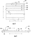
- FIGS. 4 and 5 additional views of a plurality of riblets 128 on a flowpath surface 126 are provided.
- FIG. 4 provides a close-up, plane view of a grouping 130 of a plurality of riblets 128 on a flowpath surface 126
- FIG. 5 provides a close-up, cross-sectional view of the grouping 130 of the plurality of riblets 128 on the flowpath surface 126 of FIG. 4 , taken along Line 5-5 in FIG. 4 .
- 4 and 5 may be configured in substantially the same manner as one or more of the groupings 130 of riblets 128 on the flowpath surface 126 of the turbine rotor blade 114 and/or of the platform 116 described above with reference FIG. 3 . Accordingly, the same or similar numbering may refer to the same or similar part.
- the plurality of riblets 128 in the grouping 130 depicted extend generally in a first, longitudinal direction L, which may be a downstream direction D.
- the plurality of riblets 128 define one or both of a non-uniform geometry or a non-uniform spacing along a transverse direction T, i.e., a direction perpendicular to the longitudinal direction L and parallel to the flowpath surface 126.
- the plurality of riblets 128 define a spacing 134 between adjacent riblets 128 along the transverse direction T, and the spacing 134 defined by the plurality of riblets 128 is non-uniform along the transverse direction T.
- the plurality of riblets 128 defines a plurality of sequential spacings 134 (e.g., a first spacing 134A, a second spacing 134B, a third spacing 134C, etc.).
- One or more of the plurality of sequential spacings 134A, 134B, 134C is distinct from an adjacent spacing.
- the first spacing 134A is distinct from the second spacing 134B
- the second spacing 134B is distinct from the third spacing 134C.
- FIGS. 6 and 7 views of two additional embodiments of a grouping 130 of a plurality of riblets 128 on a flowpath surface 126 are provided.
- FIG. 6 provides a close-up, cross-sectional view of a grouping 130 of a plurality of riblets 128 on a flowpath surface 126 in accordance with one exemplary embodiment of the present disclosure
- FIG. 7 provides a close-up, cross-sectional view of a grouping 130 of a plurality of riblets 128 on a flowpath surface 126 in accordance with another exemplary embodiment of the present disclosure.
- FIGS. 6 provides a close-up, cross-sectional view of a grouping 130 of a plurality of riblets 128 on a flowpath surface 126 in accordance with one exemplary embodiment of the present disclosure
- FIG. 7 provides a close-up, cross-sectional view of a grouping 130 of a plurality of riblets 128 on a flowpath surface 126 in accordance with another exemplary embodiment
- 6 and 7 may be configured in substantially the same manner as one or more of the grouping 130 of the plurality of riblets 128 on the flowpath surface 126 of the turbine rotor blade 114 and/or of the platform 116 described above with reference FIG. 3 . Accordingly, the same or similar numbering may refer to the same or similar part.
- each of the exemplary embodiments of FIGS. 6 and 7 also include a grouping 130 of a plurality of riblets 128 extending generally in a first, longitudinal direction L, which may be a downstream direction D.
- the plurality of riblets 128 depicted in FIGS. 6 and 7 define one or both of a non-uniform geometry or a non-uniform spacing along a direction perpendicular to the longitudinal direction L and parallel to the flowpath surface 126, i.e., a transverse direction T.
- each of the plurality of riblets 128 define a height 136 relative to the flowpath surface 126 and a width 138 in the transverse direction T.
- at least one of the height 136 or width 138 of each of the plurality of riblets 128 is non-uniform along the transverse direction T.
- each sequential riblet 128 in the grouping 130 depicted defines a height 136 relative to the flowpath surface 126 (e.g., a first height 136A, a second height 136B, a third height 136C, etc.).
- the heights 136A, 136B, 136C of one or more of the plurality of sequential riblets 128 is distinct from an adjacent height. Specifically, for the embodiment depicted, the first height 136A is greater than the second height 136B, which is in turn greater than the third height 136C).
- each sequential riblet 128 defines a width 138 (e.g., a first width 138A, a second width 138B, a third width 138C, etc.).
- the widths 138A, 138B, 138C of one or more of the plurality of sequential riblets 128 is distinct from an adjacent width.
- the first width 138A is greater than the second width 138B, which is, in turn, greater than the third width 138C.
- the plurality of riblets 128 in the first grouping 130A may define a first dimension proximate the platform 116 of the rotor blade 114, a second dimension proximate a center portion of the rotor blade 114 (e.g. along the radial direction R), and a third dimension proximate the tip 120 of the rotor blade 114.
- each riblet 128 in the plurality of riblets 128 may be sized according to an anticipated average thickness T BL of the local boundary layer during full load operation of a gas turbine engine into which the component is installed.
- each riblet 128 may define a height 136 of up to about two times the thickness T BL .
- each riblet 128 in the plurality of riblets 128 may define a height 136 of up to about 1.5 times the thickness T BL , or about equal to or less than the thickness T BL .
- each riblet in the plurality of riblets may define a width 138 of up to about two times the thickness T BL .
- each riblet 128 in the plurality of riblets 128 may define a width 138 of up to about 1.5 times the thickness T BL , or about equal to or less than the thickness T BL .
- each pair of adjacent riblets 128 in the plurality of riblets 128 may define a spacing 134 of up to about five times the thickness T BL .
- each pair of adjacent riblets 128 in the plurality of riblets 128 may define a spacing 134 of up to about three times the thickness T BL , up to about two times the thickness T BL , or about equal to or less than the thickness T BL .
- non-uniform when one or more the above dimensions of one or more riblets 128 within a given plurality of riblet 128 is described herein as being “non-uniform”, such may refer to a least a 10% difference from a maximum of such dimension to a minimum of such dimension.
- non-uniform when one or more of the above dimensions within a given plurality of riblets 128 is described as being non-uniform, such may refer to at least a 20% difference, at least a 30% difference, or at least a 50% difference from a maximum of such dimension to a minimum of such dimension.
- a difference between a maximum of such dimension and a minimum of such dimension may be approximately 100%.
- the dimensions above are shown with the riblets 120 defining a substantially squared or rectangular cross-sectional shape, the above parameters may apply to other embodiments of the present disclosure, wherein one or more of the riblets define any other suitable shape, such as a rounded shape, a parabolic shape, or a sawtooth shape (lambda shape).
- the height 136 of the riblets 128 may refer to a peak height
- the width 138 of the riblets 128 may refer to an average width
- a spacing 134 may refer to a spacing between peaks of adjacent riblets 128.
- FIGS. 8 and 9 views are provided of a grouping 130 of a plurality of riblets 128 on a flowpath surface 126 in accordance with yet another exemplary embodiment of the present disclosure. More particularly, FIG. 8 provides a close-up, plane view of a grouping 130 of a plurality of riblets 128 on a flowpath surface 126, and FIG. 9 provides a side, cross-sectional view of a riblet 128 in the grouping 130 of the plurality of riblets 128 on the flowpath surface 126 of FIG. 8 , along Line 9-9 of FIG. 8 .
- FIGS. 8 provides a close-up, plane view of a grouping 130 of a plurality of riblets 128 on a flowpath surface 126
- FIG. 9 provides a side, cross-sectional view of a riblet 128 in the grouping 130 of the plurality of riblets 128 on the flowpath surface 126 of FIG. 8 , along Line 9-9 of FIG. 8 .
- the same or similar numbering may refer to the same or similar part.
- each of the plurality of riblets 128 in the grouping 130 depicted extend generally in a first, longitudinal direction L, which may be a downstream direction D. Additionally, each of the plurality of riblets 128 in the grouping 130 on the flowpath surface 126 define one or both of a non-uniform geometry or a non-uniform spacing along the longitudinal direction L.
- each of the plurality of riblets 128 in the grouping 130 depicted defines a height 136 relative to the flowpath surface 126 and a width 138. At least one of the height 136 or the width 138 of each of the plurality of riblets 128 is non-uniform along the longitudinal direction L. Particularly for the embodiment depicted, both the height 136 and the width 138 of each of the plurality of riblets 128 is non-uniform along the longitudinal direction L. For example, referring particularly to FIG.
- a first riblet 128 defines an upstream width 138D (i.e., a width 138D at a first location along longitudinal direction L) and a downstream width 138E (i.e., a width 138E at a second location along the longitudinal direction L).
- the upstream width 138D is not equal to the downstream width 138E, and more particularly, the upstream width 138D is less than the downstream width 138E.
- the exemplary first riblet 128 flares outwardly/widens as it extends along the longitudinal direction L (it being appreciated that in other embodiments, the first riblet 128 may instead narrow as it extends along the longitudinal direction).
- the first riblet 128 additionally defines an upstream height 136D (i.e., a height 136D at a first location along the longitudinal direction L) and a downstream height 136E (i.e., a height 136E at a second location along the longitudinal direction L).
- the upstream height 136D is not equal to the downstream height 136E, or more particularly, the upstream height 136D is greater than the downstream height 136E.
- the exemplary first riblet 128 slants towards the flowpath surface 126 as it extends along the longitudinal direction L (it being appreciated that in other embodiments, the first riblet 128 may instead slant away from the flowpath surface 126 as it extends along the longitudinal direction).
- each of the plurality of riblets 128 defines a spacing 134 with an adjacent riblet 128.
- the spacings 134 defined by the plurality of riblets 128 are non-uniform along the longitudinal direction L, or downstream direction.
- a first and a second riblet 128 together define an upstream spacing 134D therebetween (i.e., a spacing 134D at a first location along the longitudinal direction L).
- the first and second riblet 128 also together define a downstream spacing 134E therebetween (i.e., a spacing 134E at a second location along the longitudinal direction L).
- the upstream spacing 134D defined by the first and second riblets 128 is not equal to the downstream spacing 134E defined by the first and second riblets 128, or more particularly, the upstream spacing 134D defined by the first and second riblets 128 is greater than the downstream spacing 134E defined by the first and second riblets 128. Accordingly, the first and second riblets 128 become closer to one another as they extend along the longitudinal direction L.
- inclusion of a plurality of riblets in accordance with one more embodiments of the present disclosure may allow for a decrease in heat load for the component, and thus may assist with maintaining the component within a desired operating temperature range. Moreover, as will be appreciated, inclusion of a plurality of riblets in accordance with one or more embodiments of the present disclosure may also allow for a reduction in drag on a flowpath surface on which the plurality of riblets are positioned. Further, given that the riblets may have a non-uniform spacing and/or a non-uniform geometry along a direction in which they extend, or in a direction perpendicular to the direction in which they extend, the plurality of riblets may be customized for the specific type of airflow to which they will be exposed.
- the riblets may be designed based on an anticipated amount of turbulence, airflow speed, etc. for the particular location within the gas turbine engine. Accordingly, the plurality of riblets may be designed to minimize an amount of thermal transfer, and/or minimize an amount of drag on a particular component.
- a plurality of riblets 128 described above with reference to FIGS. 2 through 7 are located on a flowpath surface 126 of a turbine rotor blade 114, in other exemplary embodiments, a plurality of riblets 128 may additionally, or alternatively, be positioned on a flowpath surface of any suitable component within the turbine section, as well as a flowpath surface of any suitable component within the compressor section.
- a grouping of a plurality of riblets may be positioned on the flowpath surface 106 of a nozzle 100 of a nozzle section (e.g., nozzle section 96 or nozzle section 98), an endwall of a nozzle section (e.g., one or both of the inner and outer end walls 102, 104 of the exemplary nozzle sections 96, 98), or any other suitable flowpath surface.
- a nozzle section e.g., nozzle section 96 or nozzle section 98
- an endwall of a nozzle section e.g., one or both of the inner and outer end walls 102, 104 of the exemplary nozzle sections 96, 98
- a grouping of a plurality of riblets in accordance with one or more exemplary aspects of the present disclosure may be located on a compressor rotor blade of a compressor rotor blade section in a stage of compressor rotor blades, and/or on a flowpath surface of a platform of a compressor rotor blades section, on a flowpath surface of a compressor nozzle, or an endwall of a compressor nozzle section of a compressor nozzle stage.
- riblets in accordance with one or more embodiments of the present disclosure may also be located on a flowpath surface of a jet nozzle exhaust section, such as the exemplary jet nozzle exhaust section 32 described above with to FIG. 1 .
- a component section including a flowpath surface with a plurality of riblets 128 thereon in accordance with an exemplary aspect of the present disclosure may be formed by adding the plurality of riblets 128 to a base geometry of the component section.
- the component section may include a base geometry, the base geometry including the flowpath surface.
- the base geometry of the component section may be formed by casting.
- the base geometry may additionally, or alternatively, be formed using one or more other methods, such as machining, joining, and additive manufacturing.
- the grouping of the plurality of riblets 128 may be added to the flowpath surface using an additive manufacturing process (also known as rapid prototyping, rapid manufacturing, and 3D printing).
- the grouping of the plurality of riblets 128 may be added to the base geometry of the component section using selective laser sintering (SLS), direct metal laser sintering (DMLS), electron beam melting (EBM), diffusion bonding, or selective heat sintering (SHS).
- SLS selective laser sintering
- DMLS direct metal laser sintering
- EBM electron beam melting
- SHS selective heat sintering
- the riblets 128 may be formed of a material different than that of the base geometry.
- the riblets 128 may be formed of a different alloy than that of the base geometry.
- the riblets 128 may instead be formed of the same material.
- the grouping 130 of the plurality of riblets 128 may completely cover a local section of the flowpath surface.
- the grouping 130 of the plurality of riblets 128 may include thin connections between adjacent riblets 128.
- adding the plurality of riblets 128 to the flowpath surface 126 may include adding only the individual riblets 128, such that the flowpath surface between adjacent riblets is exposed.
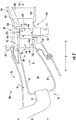
- FIG. 10 a perspective view of a turbine rotor blade section 110 in accordance with another exemplary embodiment of the present disclosure is provided.
- the exemplary rotor blade section 110 depicted in FIG. 10 may be configured in substantially the same manner as exemplary rotor blade section 110 depicted in FIG. 3 . Accordingly, the same or similar numerals may refer to same or similar part.
- the exemplary rotor blade section 110 of FIG. 10 includes a turbine rotor blade 114, a wall or platform 116, and a base 118.
- the rotor blade 114 extends outwardly along a radial direction R from the platform 116 to a tip 120 of the rotor blade 114.
- the turbine rotor blade 114 defines a leading edge 122 and an opposite trailing edge 124.
- the turbine rotor blade section 110 includes a flowpath surface 126 at least partially exposed to the core air flowpath 37.
- the turbine rotor blade section 110 depicted further includes a plurality of sequentially arranged ridges or riblets 128 on the flowpath surface 126.
- the exemplary riblets 128 extend in a non-linear direction along the flowpath surface 126 (i.e., the plurality of riblets 128 extend along a longitudinal direction, the longitudinal direction being a non-linear direction).
- the exemplary rotor blade section 110 includes a plurality of riblets 128 extending in a non-linear direction from the leading edge 122 towards the tip 120.
- the exemplary group 130 of riblets 128 extending in the non-linear direction from a radially outward half of the rotor blade 114 towards the tip 120.
- the rotor blade section 110 may additionally, or alternatively, include a plurality of riblets 128 extending in a non-linear direction at any other location.
- a root section (i.e., a radially inner end) on the suction side 127 of the rotor blade 114 may include riblets 128 extending in a non-linear direction.
- a nozzle section includes a plurality of riblets 128 on a nozzle (e.g., nozzle 100)
- a plurality of riblets 128 on an aft, suction side of the nozzle may extend non-linearly from an endwall region (inner or outer) towards a midspan region of the nozzle.
- the riblets 128 may extend in any suitable direction (linear or non-linear).
- a rotor blade section configured in such an exemplary manner to include a plurality of riblets 128 extending in a non-linear direction may allow for the plurality of riblets 128 to extend generally along the flowlines or streamlines of the component during operation, further reducing a drag on the component.
- FIG. 11 a flowchart of an exemplary method (200) of forming a component section of a component stage for a compressor section or a turbine section of a gas turbine engine is provided.
- the exemplary method (200) may be utilized with the exemplary gas turbine engine described above with reference to FIGS. 1 and 2 . Accordingly, the gas turbine engine may define a core air flowpath.
- the exemplary method (200) includes at (202) forming a base geometry of the component section.
- the base geometry includes a flowpath surface to be at least partially exposed to the core air flowpath when the component section is installed in the gas turbine engine.
- forming the base geometry of the component section at (202) includes at (204) forming the base geometry of the component section by casting the base geometry.
- the exemplary method (200) additionally includes at (206) forming a plurality of riblets on the flowpath surface of the base geometry of the component section using an additive manufacturing process.
- the plurality of riblets are arranged sequentially and define one or both of a nonuniform geometry or a nonuniform spacing.
- the riblets formed at (206) may be configured in the same manner as one or more of the exemplary embodiments described above with reference to FIGS. 3 through 9 . Accordingly, inclusion of the plurality of riblets formed at (206) may, e.g., increase a heat transfer for the component, and/or decrease a drag on the component during operation.
- the exemplary method (200) may instead be used during a repair of the component.
- forming at (202) the base geometry the component may include removing one or more layers of coatings previously applied to the flowpath surface of the base geometry.
- a component to be repaired may be stripped down of any environmental barrier coatings or other coatings previously applied thereto.
- any damaged aspects of the component may be removed and repaired, e.g., by brazing, or alternatively may be repaired also using an additive manufacturing process.
- the exemplary method (200) may then include at (206) forming the plurality of riblets on the flowpath surface of the base geometry the component using an additive manufacturing process.
- the exemplary method additionally includes at (208) applying one or more layers of coatings to the flowpath surface of the base geometry and the plurality of riblets formed on the flowpath surface of the base geometry.
- the one or more layers of coatings may include an environmental barrier coating, or any other suitable coating.
Abstract
A component stage for a turbomachine includes a component section. The component section includes a flowpath surface at least partially exposed to a core air flowpath (37) defined by the turbomachine, when the component stage is installed in the turbomachine. The component further includes a plurality of sequentially arranged riblets (128) on the flowpath surface, the plurality of sequentially arranged riblets (128) customized for an anticipated location of the flowpath surface within the turbomachine by defining one or both of a non-uniform geometry or a non-uniform spacing.
Description
- The present subject matter relates generally to a flowpath surface of a turbomachine including a plurality of riblets.
- A gas turbine engine generally includes a fan and a core arranged in flow communication with one another. Additionally, the core of the gas turbine engine general includes, in serial flow order, a compressor section, a combustion section, a turbine section, and an exhaust section. In operation, air is provided from the fan to an inlet of the compressor section where one or more axial compressors progressively compress the air until it reaches the combustion section. Fuel is mixed with the compressed air and burned within the combustion section to provide combustion gases. The combustion gases are routed from the combustion section to the turbine section. The flow of combustion gases through the turbine section drives the turbine section and is then routed through the exhaust section, e.g., to atmosphere.
- The turbine section typically includes a plurality of sequentially arranged stage(s) of turbine nozzles and turbine rotor blades. Each of the turbine nozzles within the various stages of turbine nozzles and each of the turbine rotor blades within the various stages of turbine rotor blades include one or more flowpath surfaces. In order to, e.g., decrease a heat load of certain of these flowpath surfaces, riblets (i.e., small ribs or fins) may be incorporated into the flowpath surface. Given a complexity associated with incorporating the riblets into the flowpath surfaces, each of the sequential riblets conventionally define a uniform geometry and spacing.
- However, different flowpath surfaces within, e.g., the turbine section are exposed to different airflow conditions. The inventor of the present disclosure has found that the different airflow conditions react differently to the uniform riblets. For example, the riblets may be beneficial given the airflow conditions at a first flowpath surface, while the riblets may actually provide detrimental effects given the airflow conditions at a second flowpath surface.
- Accordingly, the inventor of the present disclosure has discovered that it may be beneficial to customize the plurality of riblets to a specific location within the gas turbine engine at which the flowpath surface is located. More specifically, a flowpath surface for a gas turbine engine having a plurality of riblets customized to the specific location within the gas turbine engine would be particularly beneficial.
- Aspects and advantages of the invention will be set forth in part in the following description, or may be obvious from the description, or may be learned through practice of the invention.
- In one exemplary embodiment of the present disclosure a component stage for a turbomachine defining a core air flowpath is provided. The component stage includes a component section. The component section includes a flowpath surface at least partially exposed to the core air flowpath and further comprising a plurality of sequentially arranged riblets on the flowpath surface. The plurality of sequentially arranged riblets define one or both of a non-uniform geometry or a non-uniform spacing.
- In another exemplary embodiment of the present disclosure, a turbomachine is provided. The gas turbine engine includes a compressor section, and a turbine section in serial flow order and defining at least in part a core air flowpath. One of the compressor section or the turbine section includes a component stage. The component stage includes a component section. The component section includes a flowpath surface at least partially exposed to the core air flowpath and further including a plurality of sequentially arranged riblets on the flowpath surface. The plurality of sequentially arranged riblets define one or both of a non-uniform geometry or a non-uniform spacing.
- In an exemplary aspect of the present disclosure, a method of forming a component section of a component stage for a compressor section or a turbine section of a turbomachine is provided. The turbomachine defines a core air flowpath. The method includes forming a base geometry of the component section. The base geometry includes a flowpath surface to be at least partially exposed to the core air flowpath. The method also includes forming a plurality of riblets on the flowpath surface of the base geometry of the component section using an additive manufacturing process, the plurality of riblets arranged sequentially and defining one or both of a non-uniform geometry or a non-uniform spacing.
- These and other features, aspects and advantages of the present invention will become better understood with reference to the following description and appended claims. The accompanying drawings, which are incorporated in and constitute a part of this specification, illustrate embodiments of the invention and, together with the description, serve to explain the principles of the invention.
- A full and enabling disclosure of the present invention, including the best mode thereof, directed to one of ordinary skill in the art, is set forth in the specification, which makes reference to the appended figures, in which:
-
FIG. 1 is a schematic cross-sectional view of an exemplary gas turbine engine according to various embodiments of the present subject matter. -
FIG. 2 is a close-up, side view of a combustion section and a turbine section of the exemplary gas turbine engine ofFIG. 1 . -
FIG. 3 provides a perspective view of a turbine rotor blade section in accordance with an exemplary embodiment of the present disclosure, the turbine rotor blade section configured for a turbine rotor blades stage of the turbine section of the exemplary gas turbine engine ofFIG. 1 . -
FIG. 4 provides a close-up, plane view of a plurality of riblets on a flowpath surface in accordance with an exemplary embodiment of the present disclosure. -
FIG. 5 provides a cross-sectional view of the exemplary plurality of riblets on the flowpath surface ofFIG. 4 , taken along Line 5-5 inFIG. 4 . -
FIG. 6 provides a cross-sectional view of a plurality of riblets on a flowpath surface in accordance with another exemplary embodiment of the present disclosure. -
FIG. 7 provides a cross-sectional view of a plurality of riblets on a flowpath surface in accordance with yet another exemplary embodiment of the present disclosure. -
FIG. 8 provides a close-up, plane view of a plurality of riblets on a flowpath surface in accordance with still another exemplary embodiment of the present disclosure. -
FIG. 9 provides a cross-sectional view of a riblet of the plurality of riblets ofFIG. 8 , taken along Line 9-9 inFIG. 8 . -
FIG. 10 provides a perspective view of a turbine rotor blade section in accordance with another exemplary embodiment of the present disclosure. -
FIG. 11 provides a flow diagram of a method of forming a component section in accordance with an exemplary aspect of the present disclosure. - Reference will now be made in detail to present embodiments of the invention, one or more examples of which are illustrated in the accompanying drawings. The detailed description uses numerical and letter designations to refer to features in the drawings. Like or similar designations in the drawings and description have been used to refer to like or similar parts of the invention. As used herein, the terms "first", "second", and "third" may be used interchangeably to distinguish one component from another and are not intended to signify location or importance of the individual components. The terms "upstream" and "downstream" refer to the relative direction with respect to fluid flow in a fluid pathway. For example, "upstream" refers to the direction from which the fluid flows, and "downstream" refers to the direction to which the fluid flows.
- Referring now to the drawings, wherein identical numerals indicate the same elements throughout the figures,
FIG. 1 is a schematic cross-sectional view of a turbomachine in accordance with an exemplary embodiment of the present disclosure. More particularly, for the embodiment ofFIG. 1 , the turbomachine is configured as a gas turbine engine, or rather as a high-bypassturbofan jet engine 12, referred to herein as "turbofan engine 12." As shown inFIG. 1 , theturbofan engine 12 defines an axial direction A (extending parallel to alongitudinal centerline 13 provided for reference), a radial direction R, and a circumferential direction (not shown) extending about the axial direction A. In general, theturbofan 12 includes afan section 14 and acore turbine engine 16 disposed downstream from thefan section 14. - The exemplary
core turbine engine 16 depicted generally includes a substantially tubularouter casing 18 that defines anannular inlet 20. Theouter casing 18 encases and thecore turbine engine 16 includes, in serial flow relationship, a compressor section including a booster or low pressure (LP)compressor 22 and a high pressure (HP)compressor 24; acombustion section 26; a turbine section including a high pressure (HP)turbine 28 and a low pressure (LP)turbine 30; and a jetexhaust nozzle section 32. A high pressure (HP) shaft orspool 34 drivingly connects the HPturbine 28 to the HPcompressor 24. A low pressure (LP) shaft orspool 36 drivingly connects theLP turbine 30 to theLP compressor 22. Accordingly, theLP shaft 36 andHP shaft 34 are each rotary components, rotating about the axial direction A during operation of theturbofan engine 12. - Referring still to the embodiment of
FIG. 1 , thefan section 14 includes avariable pitch fan 38 having a plurality offan blades 40 coupled to adisk 42 in a spaced apart manner. As depicted, thefan blades 40 extend outwardly fromdisk 42 generally along the radial direction R. Eachfan blade 40 is rotatable relative to thedisk 42 about a pitch axis P by virtue of thefan blades 40 being operatively coupled to a suitablepitch change mechanism 44 configured to collectively vary the pitch of thefan blades 40 in unison. Thefan blades 40,disk 42, andpitch change mechanism 44 are together rotatable about thelongitudinal axis 12 byLP shaft 36 across apower gear box 46. Thepower gear box 46 includes a plurality of gears for adjusting the rotational speed of thefan 38 relative to theLP shaft 36 to a more efficient rotational fan speed. More particularly, the fan section includes a fan shaft rotatable by theLP shaft 36 across thepower gearbox 46. Accordingly, the fan shaft may also be considered a rotary component, and is similarly supported by one or more bearings. - Referring still to the exemplary embodiment of
FIG. 1 , thedisk 42 is covered by arotatable front hub 48 aerodynamically contoured to promote an airflow through the plurality offan blades 40. Additionally, theexemplary fan section 14 includes an annular fan casing orouter nacelle 50 that circumferentially surrounds thefan 38 and/or at least a portion of thecore turbine engine 16. Theexemplary nacelle 50 is supported relative to thecore turbine engine 16 by a plurality of circumferentially-spaced outlet guide vanes 52. Moreover, adownstream section 54 of thenacelle 50 extends over an outer portion of thecore turbine engine 16 so as to define abypass airflow passage 56 therebetween. - During operation of the
turbofan engine 12, a volume ofair 58 enters the turbofan 10 through an associatedinlet 60 of thenacelle 50 and/orfan section 14. As the volume ofair 58 passes across thefan blades 40, a first portion of theair 58 as indicated byarrows 62 is directed or routed into thebypass airflow passage 56 and a second portion of theair 58 as indicated by arrow 64 is directed or routed into thecore air flowpath 37, or more specifically into theLP compressor 22. The ratio between the first portion ofair 62 and the second portion of air 64 is commonly known as a bypass ratio. The pressure of the second portion of air 64 is then increased as it is routed through the high pressure (HP)compressor 24 and into thecombustion section 26, where it is mixed with fuel and burned to providecombustion gases 66. - The
combustion gases 66 are routed through theHP turbine 28 where a portion of thermal and/or kinetic energy from thecombustion gases 66 is extracted via sequential stages of HP turbine stator vanes 68 that are coupled to theouter casing 18 and HPturbine rotor blades 70 that are coupled to the HP shaft orspool 34, thus causing the HP shaft orspool 34 to rotate, thereby supporting operation of theHP compressor 24. Thecombustion gases 66 are then routed through theLP turbine 30 where a second portion of thermal and kinetic energy is extracted from thecombustion gases 66 via sequential stages of LPturbine stator vanes 72 that are coupled to theouter casing 18 and LPturbine rotor blades 74 that are coupled to the LP shaft orspool 36, thus causing the LP shaft orspool 36 to rotate, thereby supporting operation of theLP compressor 22 and/or rotation of thefan 38. - The
combustion gases 66 are subsequently routed through the jetexhaust nozzle section 32 of thecore turbine engine 16 to provide propulsive thrust. Simultaneously, the pressure of the first portion ofair 62 is substantially increased as the first portion ofair 62 is routed through thebypass airflow passage 56 before it is exhausted from a fannozzle exhaust section 76 of the turbofan 10, also providing propulsive thrust. TheHP turbine 28, theLP turbine 30, and the jetexhaust nozzle section 32 at least partially define ahot gas path 78 for routing thecombustion gases 66 through thecore turbine engine 16. - It should be appreciated, however, that the
exemplary turbofan engine 12 depicted inFIG. 1 is provided by way of example only, and that in other exemplary embodiments, theturbofan engine 12 may have any other suitable configuration. It should also be appreciated, that in still other exemplary embodiments, aspects of the present disclosure may be incorporated into any other suitable gas turbine engine. For example, in other exemplary embodiments, aspects of the present disclosure may be incorporated into, e.g., a turboprop engine, a turboshaft engine, or a turbojet engine. Further, in still other embodiments, aspects of the present disclosure may be incorporated into any other suitable turbomachine, including, without limitation, a steam turbine, a centrifugal compressor, and/or a turbocharger. - Referring now to
FIG. 2 , a close-up, cross-sectional view is provided of the turbofan engine 10 ofFIG. 1 , and particularly of thecombustion section 26 and theHP turbine 28 of the turbine section. Thecombustion section 26 depicted generally includes acombustor 79 having acombustion chamber 80 defined by aninner liner 82 and anouter liner 84, thecombustion chamber 80 extending generally along the axial direction A from aforward end 86 to anaft end 88. A plurality offuel nozzles 90 are positioned at theforward end 86 of thecombustion chamber 80 for providing thecombustion chamber 80 with a mixture of fuel and compressed air from the compressor section. As discussed above, the fuel and air mixture is combusted within thecombustion chamber 80 to generate a flow of combustion gasses therethrough. - Downstream of the
combustion section 26, theHP turbine 28 includes a plurality of turbine component stages, each turbine component stage comprising a plurality of turbine component sections. More particularly, for the embodiment depicted, theHP turbine 28 includes a plurality of turbine nozzle stages, as well as one or more stages of turbine rotor blades. Specifically, for the embodiment depicted, theHP turbine 28 includes a firstturbine nozzle stage 92 and a secondturbine nozzle stage 94, each configured to direct a flow of combustion gasses therethrough. The firstturbine nozzle stage 92 includes a plurality ofturbine nozzle sections 96 spaced along a circumferential direction C (a direction extending about the axial direction A; seeFIG. 3 ). Notably, the firstturbine nozzle stage 92 is located immediately downstream from thecombustion section 26, and thus may also be referred to as a combustor discharge nozzle stage having a plurality of combustion discharge nozzle sections. Additionally, for the exemplary embodiment depicted, the secondturbine nozzle stage 94 also includes a plurality ofturbine nozzle sections 98 spaced along the circumferential direction C. - Each of the
turbine nozzle sections turbine nozzle 100 positioned within thecore air flowpath 37 and an endwall at least partially exposed to (and at least partially defining) thecore air flowpath 37. More particularly, eachnozzle section inner endwall 102 and anouter endwall 104, with thenozzle 100 extending generally along the radial direction R from theinner endwall 102 to theouter endwall 104. Theturbine nozzle 100,inner endwall 102, andouter endwall 104 each include aflowpath surface 106 at least partially exposed to thecore air flowpath 37. - Located immediately downstream of the first
turbine nozzle stage 92 and immediately upstream of the secondturbine nozzle stage 94, theHP turbine 28 includes a first turbinerotor blade stage 108. The first turbine rotor blades stage 108 includes a plurality of turbinerotor blade sections 110 spaced along the circumferential direction C and a firststage rotor disk 112. The plurality of turbinerotor blade sections 110 are attached to the firststage rotor disk 112, and although not depicted, theturbine rotor disk 112 is, in turn, connected to the HP shaft 34 (seeFIG. 1 ). - Referring now also to
FIG. 3 , providing a perspective view of one of the plurality of turbinerotor blade sections 110, each of the plurality of turbinerotor blade sections 110 includes aturbine rotor blade 114, a wall orplatform 116, and abase 118. Therotor blade 114 extends outwardly along the radial direction R (and along a span of the turbine rotor blade 114) from theplatform 116 to atip 120 of therotor blade 114, defining a spanwise height H relative to theplatform 116. Additionally, theturbine rotor blade 114 defines aleading edge 122 and anopposite trailing edge 124, as well as apressure side 125 and anopposite suction side 127. During operation, hot combustion gases are generated in the combustion section and flow in a downstream direction D over theturbine rotor blades 114, extracting energy therefrom for rotating therotor disk 112, which may in turn rotate theHP shaft 34. - Further, as with the plurality of
nozzle sections rotor blade section 110 includes aflowpath surface 126 at least partially exposed to thecore air flowpath 37. More particularly, theturbine rotor blade 114 and theplatform 116 each define aflowpath surface 126 at least partially exposed to (and at least partially defining) thecore air flowpath 37. Moreover, the turbinerotor blade section 110 depicted further includes a plurality of sequentially arranged ridges orriblets 128 on theflowpath surface 126, the plurality ofriblets 128 together forming ariblets grouping 130. For example, the exemplary turbinerotor blade section 110 depicted includes threegroupings 130 of a plurality of sequentially arrangedriblets 128 on theflowpath surface 126 of theturbine rotor blade 114. More particularly, theturbine rotor blade 114 depicted includes afirst grouping 130A ofriblets 128 located on theflowpath surface 126 of theturbine rotor blade 114 at theleading edge 122; asecond grouping 130B ofriblets 128 located on theflowpath surface 126 of theturbine rotor blade 114 on thepressure side 125 of theturbine rotor blade 114 proximate thetip 120; and athird grouping 130C ofriblets 128 located on theflowpath surface 126 of theturbine rotor blade 114 on thepressure side 125 of theturbine rotor blade 114 proximate theplatform 116. Therotor blade 114 may additionally include one ormore groupings 130 on the suction side 127 (not shown). Further, the turbinerotor blade section 110 includesadditional groupings 130 of sequentially arrangedriblets 128 located on theflowpath surface 126 of theplatform 116. - As will be discussed in greater detail below, the plurality of sequentially arranged
riblets 128 define one or both of a non-uniform geometry or a non-uniform spacing. More particularly, the plurality ofriblets 128 in eachriblet grouping 130 define one or both of a non-uniform geometry or anon-uniform spacing 134. For example, as is depicted inFIG. 3 , the first, second, andthird groupings riblets 128 each extend generally in a first direction, or a longitudinal direction L (seeFIG. 4 ), which for the embodiment depicted generally aligns with a downstream direction D. Additionally, for the embodiment depicted, the longitudinal direction L is a linear direction. However, as will be explained below, e.g., with reference toFIG. 10 , in other embodiments, the longitudinal direction L may be a non-linear direction. Eachriblet 128 in thegroupings length 132 along the longitudinal direction L. Thelengths 132 of theriblets 128 in each of thegroupings rotor blade 114. More particularly, thelengths 132 ofadjacent riblets 128 in a givengrouping riblets 128 is non-uniform. - Referring now to
FIGS. 4 and 5 , additional views of a plurality ofriblets 128 on aflowpath surface 126 are provided. Specifically,FIG. 4 provides a close-up, plane view of agrouping 130 of a plurality ofriblets 128 on aflowpath surface 126, andFIG. 5 provides a close-up, cross-sectional view of thegrouping 130 of the plurality ofriblets 128 on theflowpath surface 126 ofFIG. 4 , taken along Line 5-5 inFIG. 4 . Theflowpath surface 126 and grouping 130 ofriblets 128 depicted inFIGS. 4 and 5 may be configured in substantially the same manner as one or more of thegroupings 130 ofriblets 128 on theflowpath surface 126 of theturbine rotor blade 114 and/or of theplatform 116 described above with referenceFIG. 3 . Accordingly, the same or similar numbering may refer to the same or similar part. - The plurality of
riblets 128 in thegrouping 130 depicted extend generally in a first, longitudinal direction L, which may be a downstream direction D. The plurality ofriblets 128 define one or both of a non-uniform geometry or a non-uniform spacing along a transverse direction T, i.e., a direction perpendicular to the longitudinal direction L and parallel to theflowpath surface 126. Specifically, for the embodiment depicted, the plurality ofriblets 128 define aspacing 134 betweenadjacent riblets 128 along the transverse direction T, and the spacing 134 defined by the plurality ofriblets 128 is non-uniform along the transverse direction T. More particularly, the plurality ofriblets 128 defines a plurality of sequential spacings 134 (e.g., afirst spacing 134A, asecond spacing 134B, athird spacing 134C, etc.). One or more of the plurality ofsequential spacings first spacing 134A is distinct from thesecond spacing 134B, and thesecond spacing 134B is distinct from thethird spacing 134C. - Moreover, referring now to
FIGS. 6 and 7 , views of two additional embodiments of agrouping 130 of a plurality ofriblets 128 on aflowpath surface 126 are provided. Specifically,FIG. 6 provides a close-up, cross-sectional view of agrouping 130 of a plurality ofriblets 128 on aflowpath surface 126 in accordance with one exemplary embodiment of the present disclosure, andFIG. 7 provides a close-up, cross-sectional view of agrouping 130 of a plurality ofriblets 128 on aflowpath surface 126 in accordance with another exemplary embodiment of the present disclosure. The embodiments ofFIGS. 6 and 7 may be configured in substantially the same manner as one or more of thegrouping 130 of the plurality ofriblets 128 on theflowpath surface 126 of theturbine rotor blade 114 and/or of theplatform 116 described above with referenceFIG. 3 . Accordingly, the same or similar numbering may refer to the same or similar part. - Specifically, each of the exemplary embodiments of
FIGS. 6 and 7 also include agrouping 130 of a plurality ofriblets 128 extending generally in a first, longitudinal direction L, which may be a downstream direction D. As with the embodiment ofFIGS. 4 and 5 , the plurality ofriblets 128 depicted inFIGS. 6 and 7 define one or both of a non-uniform geometry or a non-uniform spacing along a direction perpendicular to the longitudinal direction L and parallel to theflowpath surface 126, i.e., a transverse direction T. More particularly, for the embodiment depicted, each of the plurality ofriblets 128 define aheight 136 relative to theflowpath surface 126 and awidth 138 in the transverse direction T. For the embodiments ofFIGS. 6 and 7 , at least one of theheight 136 orwidth 138 of each of the plurality ofriblets 128 is non-uniform along the transverse direction T. - Referring particularly to
FIG. 6 , theheights 136 of each of the plurality ofriblets 128 is non-uniform along the transverse direction T. More particularly, eachsequential riblet 128 in thegrouping 130 depicted defines aheight 136 relative to the flowpath surface 126 (e.g., afirst height 136A, asecond height 136B, athird height 136C, etc.). Theheights sequential riblets 128 is distinct from an adjacent height. Specifically, for the embodiment depicted, thefirst height 136A is greater than thesecond height 136B, which is in turn greater than thethird height 136C). - Additionally, referring now particularly to
FIG. 7 , thewidths 138 of each of the plurality ofriblets 128 is also non-uniform along the transverse direction T. More particularly, eachsequential riblet 128 defines a width 138 (e.g., afirst width 138A, asecond width 138B, athird width 138C, etc.). Thewidths sequential riblets 128 is distinct from an adjacent width. Specifically, thefirst width 138A is greater than thesecond width 138B, which is, in turn, greater than thethird width 138C. - Notably, referring again briefly to
FIG. 3 , when thegrouping 130 of the plurality ofriblets 128 is on theflowpath surface 126 of therotor blade 114, at least one of theheight 136, thewidth 138, thelength 132, or spacing 134 (collectively "dimensions") of the plurality ofriblets 128 may vary as a function of the spanwise height H of therotor blade 114. For example, the plurality ofriblets 128 in thefirst grouping 130A may define a first dimension proximate theplatform 116 of therotor blade 114, a second dimension proximate a center portion of the rotor blade 114 (e.g. along the radial direction R), and a third dimension proximate thetip 120 of therotor blade 114. - Additionally, in certain exemplary embodiments, each
riblet 128 in the plurality ofriblets 128 may be sized according to an anticipated average thickness TBL of the local boundary layer during full load operation of a gas turbine engine into which the component is installed. For example, eachriblet 128 may define aheight 136 of up to about two times the thickness TBL. For example, in certain exemplary embodiments eachriblet 128 in the plurality ofriblets 128 may define aheight 136 of up to about 1.5 times the thickness TBL, or about equal to or less than the thickness TBL. Additionally, each riblet in the plurality of riblets may define awidth 138 of up to about two times the thickness TBL. For example, in certain exemplary embodiments eachriblet 128 in the plurality ofriblets 128 may define awidth 138 of up to about 1.5 times the thickness TBL, or about equal to or less than the thickness TBL. Further, each pair ofadjacent riblets 128 in the plurality ofriblets 128 may define aspacing 134 of up to about five times the thickness TBL. For example, in certain exemplary embodiments each pair ofadjacent riblets 128 in the plurality ofriblets 128 may define aspacing 134 of up to about three times the thickness TBL, up to about two times the thickness TBL, or about equal to or less than the thickness TBL. - Furthermore, when one or more the above dimensions of one or
more riblets 128 within a given plurality ofriblet 128 is described herein as being "non-uniform", such may refer to a least a 10% difference from a maximum of such dimension to a minimum of such dimension. For example, in certain embodiments, when one or more of the above dimensions within a given plurality ofriblets 128 is described as being non-uniform, such may refer to at least a 20% difference, at least a 30% difference, or at least a 50% difference from a maximum of such dimension to a minimum of such dimension. However, in still other embodiments, for example when a minimum of such dimension approaches zero, a difference between a maximum of such dimension and a minimum of such dimension may be approximately 100%. - Moreover, it should be appreciated that although the dimensions above are shown with the
riblets 120 defining a substantially squared or rectangular cross-sectional shape, the above parameters may apply to other embodiments of the present disclosure, wherein one or more of the riblets define any other suitable shape, such as a rounded shape, a parabolic shape, or a sawtooth shape (lambda shape). In such exemplary embodiments, theheight 136 of theriblets 128 may refer to a peak height, thewidth 138 of theriblets 128 may refer to an average width, and aspacing 134 may refer to a spacing between peaks ofadjacent riblets 128. - Referring now to
FIGS. 8 and 9 , views are provided of agrouping 130 of a plurality ofriblets 128 on aflowpath surface 126 in accordance with yet another exemplary embodiment of the present disclosure. More particularly,FIG. 8 provides a close-up, plane view of agrouping 130 of a plurality ofriblets 128 on aflowpath surface 126, andFIG. 9 provides a side, cross-sectional view of ariblet 128 in thegrouping 130 of the plurality ofriblets 128 on theflowpath surface 126 ofFIG. 8 , along Line 9-9 ofFIG. 8 . The embodiments ofFIGS. 8 and 9 may also be configured in substantially the same manner as one or more of thegroupings 130 of the plurality ofriblets 128 on theflowpath surface 126 of theturbine rotor blade 114 and/or of the plurality ofriblets 128 on theplatform 116 described above with referenceFIG. 3 . Accordingly, the same or similar numbering may refer to the same or similar part. - For the exemplary embodiment of
FIGS. 8 and 9 , each of the plurality ofriblets 128 in thegrouping 130 depicted extend generally in a first, longitudinal direction L, which may be a downstream direction D. Additionally, each of the plurality ofriblets 128 in thegrouping 130 on theflowpath surface 126 define one or both of a non-uniform geometry or a non-uniform spacing along the longitudinal direction L. - Specifically, for the embodiment depicted, each of the plurality of
riblets 128 in thegrouping 130 depicted defines aheight 136 relative to theflowpath surface 126 and awidth 138. At least one of theheight 136 or thewidth 138 of each of the plurality ofriblets 128 is non-uniform along the longitudinal direction L. Particularly for the embodiment depicted, both theheight 136 and thewidth 138 of each of the plurality ofriblets 128 is non-uniform along the longitudinal direction L. For example, referring particularly toFIG. 8 , afirst riblet 128 defines anupstream width 138D (i.e., awidth 138D at a first location along longitudinal direction L) and adownstream width 138E (i.e., awidth 138E at a second location along the longitudinal direction L). Theupstream width 138D is not equal to thedownstream width 138E, and more particularly, theupstream width 138D is less than thedownstream width 138E. Accordingly, the exemplaryfirst riblet 128 flares outwardly/widens as it extends along the longitudinal direction L (it being appreciated that in other embodiments, thefirst riblet 128 may instead narrow as it extends along the longitudinal direction). - Additionally, referring now particularly to
FIG. 9 , thefirst riblet 128 additionally defines anupstream height 136D (i.e., aheight 136D at a first location along the longitudinal direction L) and adownstream height 136E (i.e., aheight 136E at a second location along the longitudinal direction L). Theupstream height 136D is not equal to thedownstream height 136E, or more particularly, theupstream height 136D is greater than thedownstream height 136E. Accordingly, the exemplaryfirst riblet 128 slants towards theflowpath surface 126 as it extends along the longitudinal direction L (it being appreciated that in other embodiments, thefirst riblet 128 may instead slant away from theflowpath surface 126 as it extends along the longitudinal direction). - As is also depicted, the exemplary embodiment of
FIGS. 8 and 9 additionally defines a non-uniform spacing. More particularly, each of the plurality ofriblets 128 defines aspacing 134 with anadjacent riblet 128. Thespacings 134 defined by the plurality of riblets 128 (i.e., between adjacent riblets 128) are non-uniform along the longitudinal direction L, or downstream direction. For example, a first and asecond riblet 128 together define anupstream spacing 134D therebetween (i.e., aspacing 134D at a first location along the longitudinal direction L). The first andsecond riblet 128 also together define adownstream spacing 134E therebetween (i.e., aspacing 134E at a second location along the longitudinal direction L). Theupstream spacing 134D defined by the first andsecond riblets 128 is not equal to thedownstream spacing 134E defined by the first andsecond riblets 128, or more particularly, theupstream spacing 134D defined by the first andsecond riblets 128 is greater than thedownstream spacing 134E defined by the first andsecond riblets 128. Accordingly, the first andsecond riblets 128 become closer to one another as they extend along the longitudinal direction L. - Inclusion of a plurality of riblets in accordance with one more embodiments of the present disclosure may allow for a decrease in heat load for the component, and thus may assist with maintaining the component within a desired operating temperature range. Moreover, as will be appreciated, inclusion of a plurality of riblets in accordance with one or more embodiments of the present disclosure may also allow for a reduction in drag on a flowpath surface on which the plurality of riblets are positioned. Further, given that the riblets may have a non-uniform spacing and/or a non-uniform geometry along a direction in which they extend, or in a direction perpendicular to the direction in which they extend, the plurality of riblets may be customized for the specific type of airflow to which they will be exposed. For example, the riblets may be designed based on an anticipated amount of turbulence, airflow speed, etc. for the particular location within the gas turbine engine. Accordingly, the plurality of riblets may be designed to minimize an amount of thermal transfer, and/or minimize an amount of drag on a particular component.
- Given the above benefits, it should be appreciated that although the plurality of
riblets 128 described above with reference toFIGS. 2 through 7 are located on aflowpath surface 126 of aturbine rotor blade 114, in other exemplary embodiments, a plurality ofriblets 128 may additionally, or alternatively, be positioned on a flowpath surface of any suitable component within the turbine section, as well as a flowpath surface of any suitable component within the compressor section. For example, in other exemplary embodiments, a grouping of a plurality of riblets may be positioned on theflowpath surface 106 of anozzle 100 of a nozzle section (e.g.,nozzle section 96 or nozzle section 98), an endwall of a nozzle section (e.g., one or both of the inner andouter end walls exemplary nozzle sections 96, 98), or any other suitable flowpath surface. Furthermore, in still other exemplary embodiments a grouping of a plurality of riblets in accordance with one or more exemplary aspects of the present disclosure may be located on a compressor rotor blade of a compressor rotor blade section in a stage of compressor rotor blades, and/or on a flowpath surface of a platform of a compressor rotor blades section, on a flowpath surface of a compressor nozzle, or an endwall of a compressor nozzle section of a compressor nozzle stage. Furthermore, in still other exemplary embodiments, riblets in accordance with one or more embodiments of the present disclosure may also be located on a flowpath surface of a jet nozzle exhaust section, such as the exemplary jetnozzle exhaust section 32 described above with toFIG. 1 . - As will be discussed in greater detail below with reference to
FIG. 11 , a component section including a flowpath surface with a plurality ofriblets 128 thereon in accordance with an exemplary aspect of the present disclosure may be formed by adding the plurality ofriblets 128 to a base geometry of the component section. For example, the component section may include a base geometry, the base geometry including the flowpath surface. The base geometry of the component section may be formed by casting. However, in other embodiments, the base geometry may additionally, or alternatively, be formed using one or more other methods, such as machining, joining, and additive manufacturing. Subsequently, the grouping of the plurality ofriblets 128 may be added to the flowpath surface using an additive manufacturing process (also known as rapid prototyping, rapid manufacturing, and 3D printing). For example, in certain exemplary aspects, the grouping of the plurality ofriblets 128 may be added to the base geometry of the component section using selective laser sintering (SLS), direct metal laser sintering (DMLS), electron beam melting (EBM), diffusion bonding, or selective heat sintering (SHS). Accordingly, it should be appreciated that in certain exemplary embodiments, theriblets 128 may be formed of a material different than that of the base geometry. For example, theriblets 128 may be formed of a different alloy than that of the base geometry. However, in other embodiments, theriblets 128 may instead be formed of the same material. - Notably, in certain embodiments, the
grouping 130 of the plurality ofriblets 128 may completely cover a local section of the flowpath surface. For example, thegrouping 130 of the plurality ofriblets 128 may include thin connections betweenadjacent riblets 128. Alternatively, adding the plurality ofriblets 128 to theflowpath surface 126 may include adding only theindividual riblets 128, such that the flowpath surface between adjacent riblets is exposed. - Referring now briefly to
FIG. 10 , a perspective view of a turbinerotor blade section 110 in accordance with another exemplary embodiment of the present disclosure is provided. The exemplaryrotor blade section 110 depicted inFIG. 10 may be configured in substantially the same manner as exemplaryrotor blade section 110 depicted inFIG. 3 . Accordingly, the same or similar numerals may refer to same or similar part. - As depicted, the exemplary
rotor blade section 110 ofFIG. 10 includes aturbine rotor blade 114, a wall orplatform 116, and abase 118. Therotor blade 114 extends outwardly along a radial direction R from theplatform 116 to atip 120 of therotor blade 114. Additionally, theturbine rotor blade 114 defines aleading edge 122 and anopposite trailing edge 124. Further, the turbinerotor blade section 110 includes aflowpath surface 126 at least partially exposed to thecore air flowpath 37. The turbinerotor blade section 110 depicted further includes a plurality of sequentially arranged ridges orriblets 128 on theflowpath surface 126. However, for the embodiment depicted, theexemplary riblets 128 extend in a non-linear direction along the flowpath surface 126 (i.e., the plurality ofriblets 128 extend along a longitudinal direction, the longitudinal direction being a non-linear direction). - Specifically, for the embodiment depicted, the exemplary
rotor blade section 110 includes a plurality ofriblets 128 extending in a non-linear direction from theleading edge 122 towards thetip 120. As is depicted, theexemplary group 130 ofriblets 128 extending in the non-linear direction from a radially outward half of therotor blade 114 towards thetip 120. It should be appreciated, that although not included in the exemplary embodiment depicted, therotor blade section 110 may additionally, or alternatively, include a plurality ofriblets 128 extending in a non-linear direction at any other location. For example, a root section (i.e., a radially inner end) on thesuction side 127 of therotor blade 114 may includeriblets 128 extending in a non-linear direction. Further, for other exemplary embodiments, e.g., wherein a nozzle section includes a plurality ofriblets 128 on a nozzle (e.g., nozzle 100), a plurality ofriblets 128 on an aft, suction side of the nozzle may extend non-linearly from an endwall region (inner or outer) towards a midspan region of the nozzle. Of course, in still other embodiments, theriblets 128 may extend in any suitable direction (linear or non-linear). - A rotor blade section configured in such an exemplary manner to include a plurality of
riblets 128 extending in a non-linear direction may allow for the plurality ofriblets 128 to extend generally along the flowlines or streamlines of the component during operation, further reducing a drag on the component. - Referring now to
FIG. 11 , a flowchart of an exemplary method (200) of forming a component section of a component stage for a compressor section or a turbine section of a gas turbine engine is provided. The exemplary method (200) may be utilized with the exemplary gas turbine engine described above with reference toFIGS. 1 and2 . Accordingly, the gas turbine engine may define a core air flowpath. - As is depicted, the exemplary method (200) includes at (202) forming a base geometry of the component section. The base geometry includes a flowpath surface to be at least partially exposed to the core air flowpath when the component section is installed in the gas turbine engine. For the exemplary embodiment depicted, forming the base geometry of the component section at (202) includes at (204) forming the base geometry of the component section by casting the base geometry.
- Further, the exemplary method (200) additionally includes at (206) forming a plurality of riblets on the flowpath surface of the base geometry of the component section using an additive manufacturing process. The plurality of riblets are arranged sequentially and define one or both of a nonuniform geometry or a nonuniform spacing. For example, in certain exemplary aspects, the riblets formed at (206) may be configured in the same manner as one or more of the exemplary embodiments described above with reference to
FIGS. 3 through 9 . Accordingly, inclusion of the plurality of riblets formed at (206) may, e.g., increase a heat transfer for the component, and/or decrease a drag on the component during operation. - Notably, in other exemplary embodiments, the exemplary method (200) may instead be used during a repair of the component. With such an exemplary aspect, instead of forming the base geometry of the component by casting at (204), forming at (202) the base geometry the component may include removing one or more layers of coatings previously applied to the flowpath surface of the base geometry. For example, a component to be repaired may be stripped down of any environmental barrier coatings or other coatings previously applied thereto. Additionally, any damaged aspects of the component may be removed and repaired, e.g., by brazing, or alternatively may be repaired also using an additive manufacturing process. The exemplary method (200) may then include at (206) forming the plurality of riblets on the flowpath surface of the base geometry the component using an additive manufacturing process.
- Referring still to
FIG. 11 , the exemplary method additionally includes at (208) applying one or more layers of coatings to the flowpath surface of the base geometry and the plurality of riblets formed on the flowpath surface of the base geometry. The one or more layers of coatings may include an environmental barrier coating, or any other suitable coating. - This written description uses examples to disclose the invention, including the best mode, and also to enable any person skilled in the art to practice the invention, including making and using any devices or systems and performing any incorporated methods. The patentable scope of the invention is defined by the claims, and may include other examples that occur to those skilled in the art. Such other examples are intended to be within the scope of the claims if they include structural elements that do not differ from the literal language of the claims, or if they include equivalent structural elements with insubstantial differences from the literal languages of the claims.
- Various aspects and embodiments of the present invention are defined by the following numbered clauses:
- 1. A component stage for a turbomachine defining a core air flowpath, the component stage comprising:
- a component section, the component section comprising a flowpath surface at least partially exposed to the core air flowpath and further comprising a plurality of sequentially arranged riblets on the flowpath surface, the plurality of sequentially arranged riblets defining one or both of a non-uniform geometry or a non-uniform spacing.
- 2. The component stage of clause 1, wherein each of the plurality of riblets extend generally in a first direction, and wherein each of the plurality of riblets define one or both of a non-uniform geometry or a non-uniform spacing along the first direction.
- 3. The component stage of clause 1 or 2, wherein each of the plurality of riblets define a height relative to the flowpath surface and a width, and wherein at least one of the height or width of each of the plurality of riblets is non-uniform along the first direction.
- 4. The component stage of any preceding clause, wherein the plurality of riblets define a spacing between adjacent riblets, and wherein the spacing defined by the plurality of riblets is non-uniform along the first direction.
- 5. The component stage of any preceding clause, wherein the plurality of riblets extend generally in a first direction, and wherein the plurality of riblets define one or both of a non-uniform geometry or a non-uniform in a direction perpendicular to the first direction.
- 6. The component stage of any preceding clause, wherein each of the plurality of riblets define a height relative to the flowpath surface and a width, and wherein at least one of the height or width of each of the plurality of riblets is non-uniform along a direction perpendicular to the first direction.
- 7. The component stage of any preceding clause, wherein the plurality of riblets define a spacing between adjacent riblets, and wherein the spacing defined by the plurality riblets is non-uniform along a direction perpendicular to the first direction.
- 8. The component stage of any preceding clause, wherein the component section comprises at least one of a nozzle or a rotor blade, and wherein the flowpath surface of the component section comprises a surface of the nozzle or the rotor blade.
- 9. The component stage of any preceding clause, wherein each of the plurality of riblets define a height relative to the flowpath surface and a width, and wherein at least one of the height or width of the plurality of riblets varies as a function of a spanwise height of the nozzle or rotor blade.
- 10. The component stage of any preceding clause, wherein the component section comprises an endwall, and wherein the flowpath surface of the component section comprises a surface of the endwall.
- 11. The component stage of any preceding clause, wherein the component section comprises a base geometry, wherein the base geometry comprises the flowpath surface, wherein the base geometry is formed by casting, and wherein the plurality of riblets are added to the flowpath surface using an additive manufacturing process.
- 12. The component stage of any preceding clause, wherein the plurality of riblets extend in a non-linear direction.
- 13. The component stage of any preceding clause, wherein the component section comprises a rotor blade defining a leading edge and a tip, wherein the flowpath surface of the component section comprises a surface of the rotor blade, and wherein the plurality of riblets extend in a non-linear direction from the leading edge towards the tip.
- 14. A turbomachine comprising:
- a compressor section and a turbine section in serial flow order and defining at least in part a core air flowpath, one of the compressor section or the turbine section comprising a component stage, the component stage comprising a component section, the component section comprising a flowpath surface at least partially exposed to the core air flowpath and further comprising a plurality of sequentially arranged riblets on the flowpath surface, the plurality of sequentially arranged riblets defining one or both of a non-uniform geometry or a non-uniform spacing.
- 15. A method of forming a component section of a component stage for a compressor section or a turbine section of a turbomachine, the turbomachine defining a core air flowpath, the method comprising:
- forming a base geometry of the component section, the base geometry comprising a flowpath surface to be at least partially exposed to the core air flowpath; and
- forming a plurality of riblets on the flowpath surface of the base geometry of the component section using an additive manufacturing process, the plurality of riblets arranged sequentially and defining one or both of a non-uniform geometry or a non-uniform spacing.
- 16. The method of clause 15, wherein forming the base geometry of the component section comprises forming the base geometry of the component section by casting.
- 17. The method of
clause 15 or 16, further comprising:- applying one or more layers of coatings to the flowpath surface of the base geometry and the plurality of riblets formed on the flowpath surface of the base geometry.
- 18. The method of any of clauses 15 to 17, wherein forming the base geometry of the component section comprises removing one or more layers of coatings previously applied to the flowpath surface of the base geometry.
- 19. The method of any of clauses 15 to 18, wherein each of the plurality of riblets extend generally in a first direction, and wherein the plurality of riblets define one or both of a non-uniform geometry or a non-uniform spacing along the first direction.
- 20. The method of any of clauses 15 to 19, wherein each of the plurality of riblets define a height relative to the flowpath surface and a width, and wherein at least one of the height or width of each of the plurality of riblets is non-uniform along the first direction.
Claims (15)
- A component stage for a turbomachine defining a core air flowpath (37), the component stage comprising:a component section, the component section comprising a flowpath surface at least partially exposed to the core air flowpath (37) and further comprising a plurality of sequentially arranged riblets (128) on the flowpath surface, the plurality of sequentially arranged riblets (128) defining one or both of a non-uniform geometry or a non-uniform spacing.
- The component stage of claim 1, wherein each of the plurality of riblets (128) extend generally in a first direction, and wherein each of the plurality of riblets (128) define one or both of a non-uniform geometry or a non-uniform spacing along the first direction.
- The component stage of claim 1 or claim 2, wherein the plurality of riblets (128) extend generally in a first direction, and wherein the plurality of riblets (128) define one or both of a non-uniform geometry or a non-uniform in a direction perpendicular to the first direction.
- The component stage of any preceding claim, wherein the component section comprises at least one of a nozzle (100) or a rotor blade (114), and wherein the flowpath surface of the component section comprises a surface of the nozzle (100) or the rotor blade (114).
- The component stage of claim 4, wherein each of the plurality of riblets (128) define a height (136) relative to the flowpath surface and a width (138), and wherein at least one of the height (136) or width (138) of the plurality of riblets (128) varies as a function of a spanwise height (S) of the nozzle (100) or rotor blade (114).
- The component stage of any preceding claim, wherein the component section comprises a base geometry, wherein the base geometry comprises the flowpath surface, wherein the base geometry is formed by casting, and wherein the plurality of riblets (128) are added to the flowpath surface using an additive manufacturing process.
- The component stage of any preceding claim, wherein the plurality of riblets (128) extend in a non-linear direction.
- The component stage of any preceding claim, wherein the component section comprises a rotor blade defining a leading edge and a tip, wherein the flowpath surface of the component section comprises a surface of the rotor blade, and wherein the plurality of riblets extend in a non-linear direction from the leading edge towards the tip.
- A method of forming a component section of a component stage for a compressor section or a turbine section of a turbomachine, the turbomachine defining a core air flowpath, the method comprising:forming a base geometry of the component section, the base geometry comprising a flowpath surface to be at least partially exposed to the core air flowpath; andforming a plurality of riblets on the flowpath surface of the base geometry of the component section using an additive manufacturing process, the plurality of riblets arranged sequentially and defining one or both of a non-uniform geometry or a non-uniform spacing.
- The method of claim 9, wherein forming the base geometry of the component section comprises forming the base geometry of the component section by casting.
- The method of claim 9 or claim 10, further comprising:applying one or more layers of coatings to the flowpath surface of the base geometry and the plurality of riblets (128) formed on the flowpath surface of the base geometry.
- The method of any of claims 9 to 11, wherein forming the base geometry of the component section comprises removing one or more layers of coatings previously applied to the flowpath surface of the base geometry.
- The method of any of claims 9 to 12, wherein each of the plurality of riblets (128) extend generally in a first direction, and wherein the plurality of riblets (128) define one or both of a non-uniform geometry or a non-uniform spacing along the first direction.
- The method of claim 13, wherein each of the plurality of riblets define a height (136) relative to the flowpath surface and a width (138), and wherein at least one of the height (136) or width (138) of each of the plurality of riblets (128) is non-uniform along the first direction.
- A turbomachine comprising:a compressor section and a turbine section in serial flow order and defining at least in part a core air flowpath, one of the compressor section or the turbine section comprising a component stage, the component stage comprising a component section, the component section comprising a flowpath surface at least partially exposed to the core air flowpath and further comprising a plurality of sequentially arranged riblets (128) on the flowpath surface, the plurality of sequentially arranged riblets (128) defining one or both of a non-uniform geometry or a non-uniform spacing.
Applications Claiming Priority (1)
| Application Number | Priority Date | Filing Date | Title |
|---|---|---|---|
| US15/042,635 US10450867B2 (en) | 2016-02-12 | 2016-02-12 | Riblets for a flowpath surface of a turbomachine |
Publications (1)
| Publication Number | Publication Date |
|---|---|
| EP3214267A1 true EP3214267A1 (en) | 2017-09-06 |
Family
ID=58009745
Family Applications (1)
| Application Number | Title | Priority Date | Filing Date |
|---|---|---|---|
| EP17155413.2A Withdrawn EP3214267A1 (en) | 2016-02-12 | 2017-02-09 | Riblets for a flowpath surface of a turbomachine |
Country Status (5)
| Country | Link |
|---|---|
| US (1) | US10450867B2 (en) |
| EP (1) | EP3214267A1 (en) |
| JP (1) | JP2017141830A (en) |
| CN (1) | CN107084000A (en) |
| CA (1) | CA2957456A1 (en) |
Cited By (1)
| Publication number | Priority date | Publication date | Assignee | Title |
|---|---|---|---|---|
| WO2020254764A1 (en) * | 2019-06-20 | 2020-12-24 | Safran Aircraft Engines | Method for coating a turbomachine guide vane and associated guide vane |
Families Citing this family (29)
| Publication number | Priority date | Publication date | Assignee | Title |
|---|---|---|---|---|
| US10895161B2 (en) * | 2016-10-28 | 2021-01-19 | Honeywell International Inc. | Gas turbine engine airfoils having multimodal thickness distributions |
| US10907648B2 (en) * | 2016-10-28 | 2021-02-02 | Honeywell International Inc. | Airfoil with maximum thickness distribution for robustness |
| US11111858B2 (en) * | 2017-01-27 | 2021-09-07 | General Electric Company | Cool core gas turbine engine |
| US20180216575A1 (en) * | 2017-01-27 | 2018-08-02 | General Electric Company | Cool core gas turbine engine |
| CN107524523B (en) * | 2017-08-17 | 2020-06-02 | 中国科学院工程热物理研究所 | Light-weight force-transmission support plate structure and casing with same |
| CN107476885B (en) * | 2017-09-15 | 2019-12-20 | 中国科学院工程热物理研究所 | Structure capable of realizing coordinated deformation of inner ring casing and outer ring casing in high-temperature environment |
| GB201716178D0 (en) * | 2017-10-04 | 2017-11-15 | Rolls Royce Plc | Blade or vane for a gas turbine engine |
| US10760600B2 (en) * | 2017-10-27 | 2020-09-01 | General Electric Company | Method of applying riblets to an aerodynamic surface |
| US10605087B2 (en) | 2017-12-14 | 2020-03-31 | United Technologies Corporation | CMC component with flowpath surface ribs |
| DE102018112562A1 (en) * | 2018-05-25 | 2019-11-28 | Man Energy Solutions Se | Grille of a turbomachine and method for producing the same |
| WO2020106343A2 (en) * | 2018-08-22 | 2020-05-28 | Peer Belt Inc. | Method, system and apparatus for reducing fluid drag |
| BE1026579B1 (en) * | 2018-08-31 | 2020-03-30 | Safran Aero Boosters Sa | PROTUBERANCE VANE FOR TURBOMACHINE COMPRESSOR |
| US11047239B2 (en) | 2018-12-03 | 2021-06-29 | General Electric Company | Method of forming a cure tool and method of forming a textured surface using a cure tool |
| US10767492B2 (en) | 2018-12-18 | 2020-09-08 | General Electric Company | Turbine engine airfoil |
| US11352889B2 (en) | 2018-12-18 | 2022-06-07 | General Electric Company | Airfoil tip rail and method of cooling |
| US11566527B2 (en) | 2018-12-18 | 2023-01-31 | General Electric Company | Turbine engine airfoil and method of cooling |
| US11499433B2 (en) | 2018-12-18 | 2022-11-15 | General Electric Company | Turbine engine component and method of cooling |
| US11174736B2 (en) | 2018-12-18 | 2021-11-16 | General Electric Company | Method of forming an additively manufactured component |
| US10844728B2 (en) | 2019-04-17 | 2020-11-24 | General Electric Company | Turbine engine airfoil with a trailing edge |
| CN115485452A (en) * | 2020-04-22 | 2022-12-16 | 株式会社尼康 | Blade, machining system and machining method |
| US11319833B2 (en) * | 2020-04-24 | 2022-05-03 | General Electric Company | Fan case with crack-arresting backsheet structure and removable containment cartridge |
| US11428160B2 (en) | 2020-12-31 | 2022-08-30 | General Electric Company | Gas turbine engine with interdigitated turbine and gear assembly |
| IT202100000296A1 (en) | 2021-01-08 | 2022-07-08 | Gen Electric | TURBINE ENGINE WITH VANE HAVING A SET OF DIMPLES |
| US20220307381A1 (en) * | 2021-03-24 | 2022-09-29 | General Electric Company | Component assembly for a combustion section of a gas turbine engine |
| US11725524B2 (en) | 2021-03-26 | 2023-08-15 | General Electric Company | Engine airfoil metal edge |
| WO2022225897A1 (en) | 2021-04-20 | 2022-10-27 | Nikon Corporation | Systems and methods for measuring height properties of surfaces |
| CN113153447B (en) * | 2021-04-25 | 2023-08-01 | 西安交通大学 | Prerotation structure for strengthening cooling of leakage flow of end wall of turbine stationary blade |
| US11725525B2 (en) | 2022-01-19 | 2023-08-15 | Rolls-Royce North American Technologies Inc. | Engine section stator vane assembly with band stiffness features for turbine engines |
| US11767607B1 (en) | 2022-07-13 | 2023-09-26 | General Electric Company | Method of depositing a metal layer on a component |
Citations (10)
| Publication number | Priority date | Publication date | Assignee | Title |
|---|---|---|---|---|
| JPH08247093A (en) * | 1995-03-06 | 1996-09-24 | Takasago Thermal Eng Co Ltd | Fan blade of centrifugal blower |
| US6092766A (en) * | 1995-12-12 | 2000-07-25 | Ulrich Laroche | Process for forming a surface for contact with a flowing fluid and body with such surface regions |
| US6213711B1 (en) * | 1997-04-01 | 2001-04-10 | Siemens Aktiengesellschaft | Steam turbine and blade or vane for a steam turbine |
| EP1371813A1 (en) * | 2002-06-13 | 2003-12-17 | ALSTOM (Switzerland) Ltd | Blading of a turbomachine |
| US20080273985A1 (en) * | 2006-02-24 | 2008-11-06 | Aeromet Technologies, Inc. | Roughened Coatings for Gas Turbine Engine Components |
| US20100127125A1 (en) * | 2008-08-05 | 2010-05-27 | Ming Li | Metal sheets and plates having friction-reducing textured surfaces and methods of manufacturing same |
| US20110164981A1 (en) * | 2010-01-04 | 2011-07-07 | General Electric Company | Patterned turbomachine component and method of forming a pattern on a turbomachine component |
| US20110262705A1 (en) * | 2011-03-30 | 2011-10-27 | General Electric Company Global Research | Microstructures for reducing noise of a fluid dynamic structure |
| US20130164488A1 (en) * | 2011-12-22 | 2013-06-27 | General Electric Company | Airfoils for wake desensitization and method for fabricating same |
| WO2014114988A1 (en) * | 2013-01-25 | 2014-07-31 | Peter Ireland | Energy efficiency improvements for turbomachinery |
Family Cites Families (22)
| Publication number | Priority date | Publication date | Assignee | Title |
|---|---|---|---|---|
| US2899128A (en) * | 1959-08-11 | Vaghi | ||
| US2238749A (en) * | 1939-01-30 | 1941-04-15 | Clarence B Swift | Fan blade |
| BE638547A (en) * | 1962-10-29 | 1900-01-01 | ||
| GB1240995A (en) * | 1967-11-06 | 1971-07-28 | Hawker Siddeley Aviation Ltd | Improvements in or relating to aircraft lifting surfaces |
| US3776363A (en) * | 1971-05-10 | 1973-12-04 | A Kuethe | Control of noise and instabilities in jet engines, compressors, turbines, heat exchangers and the like |
| US4128363A (en) * | 1975-04-30 | 1978-12-05 | Kabushiki Kaisha Toyota Chuo Kenkyusho | Axial flow fan |
| US4108573A (en) * | 1977-01-26 | 1978-08-22 | Westinghouse Electric Corp. | Vibratory tuning of rotatable blades for elastic fluid machines |
| JPS5472507A (en) * | 1977-11-22 | 1979-06-11 | Toyota Central Res & Dev Lab Inc | Axial flow fan with supplementary blades |
| US5368508A (en) * | 1993-06-08 | 1994-11-29 | Whittington; Burl D. | Marine propeller with transversal converging ribs |
| US6406260B1 (en) * | 1999-10-22 | 2002-06-18 | Pratt & Whitney Canada Corp. | Heat transfer promotion structure for internally convectively cooled airfoils |
| US7993105B2 (en) * | 2005-12-06 | 2011-08-09 | United Technologies Corporation | Hollow fan blade for gas turbine engine |
| US8884182B2 (en) | 2006-12-11 | 2014-11-11 | General Electric Company | Method of modifying the end wall contour in a turbine using laser consolidation and the turbines derived therefrom |
| US8083487B2 (en) * | 2007-07-09 | 2011-12-27 | General Electric Company | Rotary airfoils and method for fabricating same |
| FR2927356B1 (en) * | 2008-02-07 | 2013-03-01 | Snecma | AUBES FOR WHEEL WITH TURBOMACHINE AUBES WITH GROOVE FOR COOLING. |
| FR2938502B1 (en) * | 2008-11-14 | 2010-12-10 | Snecma | TURBOMACHINE COMPRISING A NON-CARNEY PROPELLER EQUIPPED WITH AIR GUIDING MEANS |
| US8267718B2 (en) | 2010-04-07 | 2012-09-18 | Panduit Corp. | High data rate electrical connector and cable assembly |
| US20130146217A1 (en) | 2011-12-09 | 2013-06-13 | Nicholas Joseph Kray | Method of Applying Surface Riblets to an Aerodynamic Surface |
| US9416665B2 (en) * | 2012-02-15 | 2016-08-16 | United Technologies Corporation | Cooling hole with enhanced flow attachment |
| CH706090A1 (en) * | 2012-02-17 | 2013-08-30 | Alstom Technology Ltd | A method for manufacturing a near-surface cooling passage in a thermally highly stressed component and component with such a channel. |
| US20140102684A1 (en) * | 2012-10-15 | 2014-04-17 | General Electric Company | Hot gas path component cooling film hole plateau |
| US20150003995A1 (en) | 2012-11-14 | 2015-01-01 | United Technologies Corporation | Aircraft engine component with locally tailored materials |
| US8939410B2 (en) * | 2013-02-06 | 2015-01-27 | Reginald J Exton | Boundary layer flow disruptors for delaying transition to turbulent flow |
-
2016
- 2016-02-12 US US15/042,635 patent/US10450867B2/en not_active Expired - Fee Related
-
2017
- 2017-02-07 JP JP2017020010A patent/JP2017141830A/en active Pending
- 2017-02-09 EP EP17155413.2A patent/EP3214267A1/en not_active Withdrawn
- 2017-02-09 CA CA2957456A patent/CA2957456A1/en not_active Abandoned
- 2017-02-10 CN CN201710073703.0A patent/CN107084000A/en active Pending
Patent Citations (10)
| Publication number | Priority date | Publication date | Assignee | Title |
|---|---|---|---|---|
| JPH08247093A (en) * | 1995-03-06 | 1996-09-24 | Takasago Thermal Eng Co Ltd | Fan blade of centrifugal blower |
| US6092766A (en) * | 1995-12-12 | 2000-07-25 | Ulrich Laroche | Process for forming a surface for contact with a flowing fluid and body with such surface regions |
| US6213711B1 (en) * | 1997-04-01 | 2001-04-10 | Siemens Aktiengesellschaft | Steam turbine and blade or vane for a steam turbine |
| EP1371813A1 (en) * | 2002-06-13 | 2003-12-17 | ALSTOM (Switzerland) Ltd | Blading of a turbomachine |
| US20080273985A1 (en) * | 2006-02-24 | 2008-11-06 | Aeromet Technologies, Inc. | Roughened Coatings for Gas Turbine Engine Components |
| US20100127125A1 (en) * | 2008-08-05 | 2010-05-27 | Ming Li | Metal sheets and plates having friction-reducing textured surfaces and methods of manufacturing same |
| US20110164981A1 (en) * | 2010-01-04 | 2011-07-07 | General Electric Company | Patterned turbomachine component and method of forming a pattern on a turbomachine component |
| US20110262705A1 (en) * | 2011-03-30 | 2011-10-27 | General Electric Company Global Research | Microstructures for reducing noise of a fluid dynamic structure |
| US20130164488A1 (en) * | 2011-12-22 | 2013-06-27 | General Electric Company | Airfoils for wake desensitization and method for fabricating same |
| WO2014114988A1 (en) * | 2013-01-25 | 2014-07-31 | Peter Ireland | Energy efficiency improvements for turbomachinery |
Cited By (3)
| Publication number | Priority date | Publication date | Assignee | Title |
|---|---|---|---|---|
| WO2020254764A1 (en) * | 2019-06-20 | 2020-12-24 | Safran Aircraft Engines | Method for coating a turbomachine guide vane and associated guide vane |
| FR3097452A1 (en) * | 2019-06-20 | 2020-12-25 | Safran Aircraft Engines | PROCESS FOR COATING A TURBOMACHINE RECTIFIER VANE, ASSOCIATED RECTIFIER VANE |
| US11898466B2 (en) | 2019-06-20 | 2024-02-13 | Safran Aircraft Engines | Method for coating a turbomachine guide vane, associated guide vane |
Also Published As
| Publication number | Publication date |
|---|---|
| JP2017141830A (en) | 2017-08-17 |
| CA2957456A1 (en) | 2017-08-12 |
| US20170234134A1 (en) | 2017-08-17 |
| US10450867B2 (en) | 2019-10-22 |
| CN107084000A (en) | 2017-08-22 |
Similar Documents
| Publication | Publication Date | Title |
|---|---|---|
| US10450867B2 (en) | Riblets for a flowpath surface of a turbomachine | |
| US10436068B2 (en) | Flowpath contouring | |
| CN107013248B (en) | Method and system for improving turbine blade performance | |
| US10495309B2 (en) | Surface contouring of a flowpath wall of a gas turbine engine | |
| US10794396B2 (en) | Inlet pre-swirl gas turbine engine | |
| US20180363676A1 (en) | Inlet pre-swirl gas turbine engine | |
| US10260354B2 (en) | Airfoil trailing edge cooling | |
| EP3075964A1 (en) | System for cooling a turbine engine | |
| US20210010376A1 (en) | Fluid cooling systems for a gas turbine engine | |
| EP3187691A1 (en) | Turbofan engine assembly and method of assembling the same | |
| US11952900B2 (en) | Variable guide vane sealing | |
| EP3078807B1 (en) | Cooling passages for a gas turbine engine component | |
| EP2956257B1 (en) | Gas turbine engine component cooling passage and space eating core | |
| CN107084002B (en) | Turbine assembly and method of manufacture | |
| EP3203027A1 (en) | Turbine engine airfoil with cooling | |
| US10787913B2 (en) | Airfoil cooling circuit | |
| US20200024986A1 (en) | Gas turbine engine component | |
| US10724390B2 (en) | Collar support assembly for airfoils |
Legal Events
| Date | Code | Title | Description |
|---|---|---|---|
| PUAI | Public reference made under article 153(3) epc to a published international application that has entered the european phase |
Free format text: ORIGINAL CODE: 0009012 |
|
| AK | Designated contracting states |
Kind code of ref document: A1 Designated state(s): AL AT BE BG CH CY CZ DE DK EE ES FI FR GB GR HR HU IE IS IT LI LT LU LV MC MK MT NL NO PL PT RO RS SE SI SK SM TR |
|
| AX | Request for extension of the european patent |
Extension state: BA ME |
|
| STAA | Information on the status of an ep patent application or granted ep patent |
Free format text: STATUS: THE APPLICATION IS DEEMED TO BE WITHDRAWN |
|
| 18D | Application deemed to be withdrawn |
Effective date: 20180307 |