EP3211220A1 - Vortex generator for wind turbine blade, wind turbine blade, wind turbine power generating apparatus, and method of mounting vortex generator - Google Patents
Vortex generator for wind turbine blade, wind turbine blade, wind turbine power generating apparatus, and method of mounting vortex generator Download PDFInfo
- Publication number
- EP3211220A1 EP3211220A1 EP16189464.7A EP16189464A EP3211220A1 EP 3211220 A1 EP3211220 A1 EP 3211220A1 EP 16189464 A EP16189464 A EP 16189464A EP 3211220 A1 EP3211220 A1 EP 3211220A1
- Authority
- EP
- European Patent Office
- Prior art keywords
- wind turbine
- vortex generator
- turbine blade
- platform portion
- marks
- Prior art date
- Legal status (The legal status is an assumption and is not a legal conclusion. Google has not performed a legal analysis and makes no representation as to the accuracy of the status listed.)
- Granted
Links
- 238000000034 method Methods 0.000 title claims description 14
- 238000010586 diagram Methods 0.000 description 8
- 238000000926 separation method Methods 0.000 description 6
- 239000012530 fluid Substances 0.000 description 5
- 230000002093 peripheral effect Effects 0.000 description 4
- 239000000126 substance Substances 0.000 description 4
- 238000011144 upstream manufacturing Methods 0.000 description 4
- 238000013459 approach Methods 0.000 description 2
- 238000004519 manufacturing process Methods 0.000 description 2
- 238000000465 moulding Methods 0.000 description 2
- 239000000565 sealant Substances 0.000 description 2
- 239000000853 adhesive Substances 0.000 description 1
- 239000002390 adhesive tape Substances 0.000 description 1
- 230000000694 effects Effects 0.000 description 1
- 238000009434 installation Methods 0.000 description 1
- 239000000463 material Substances 0.000 description 1
- 238000005259 measurement Methods 0.000 description 1
- 238000012986 modification Methods 0.000 description 1
- 230000004048 modification Effects 0.000 description 1
Images


Classifications
-
- F—MECHANICAL ENGINEERING; LIGHTING; HEATING; WEAPONS; BLASTING
- F03—MACHINES OR ENGINES FOR LIQUIDS; WIND, SPRING, OR WEIGHT MOTORS; PRODUCING MECHANICAL POWER OR A REACTIVE PROPULSIVE THRUST, NOT OTHERWISE PROVIDED FOR
- F03D—WIND MOTORS
- F03D1/00—Wind motors with rotation axis substantially parallel to the air flow entering the rotor
- F03D1/06—Rotors
- F03D1/065—Rotors characterised by their construction elements
- F03D1/0675—Rotors characterised by their construction elements of the blades
-
- F—MECHANICAL ENGINEERING; LIGHTING; HEATING; WEAPONS; BLASTING
- F03—MACHINES OR ENGINES FOR LIQUIDS; WIND, SPRING, OR WEIGHT MOTORS; PRODUCING MECHANICAL POWER OR A REACTIVE PROPULSIVE THRUST, NOT OTHERWISE PROVIDED FOR
- F03D—WIND MOTORS
- F03D1/00—Wind motors with rotation axis substantially parallel to the air flow entering the rotor
- F03D1/06—Rotors
- F03D1/0608—Rotors characterised by their aerodynamic shape
- F03D1/0633—Rotors characterised by their aerodynamic shape of the blades
-
- F—MECHANICAL ENGINEERING; LIGHTING; HEATING; WEAPONS; BLASTING
- F03—MACHINES OR ENGINES FOR LIQUIDS; WIND, SPRING, OR WEIGHT MOTORS; PRODUCING MECHANICAL POWER OR A REACTIVE PROPULSIVE THRUST, NOT OTHERWISE PROVIDED FOR
- F03D—WIND MOTORS
- F03D13/00—Assembly, mounting or commissioning of wind motors; Arrangements specially adapted for transporting wind motor components
- F03D13/10—Assembly of wind motors; Arrangements for erecting wind motors
-
- F—MECHANICAL ENGINEERING; LIGHTING; HEATING; WEAPONS; BLASTING
- F05—INDEXING SCHEMES RELATING TO ENGINES OR PUMPS IN VARIOUS SUBCLASSES OF CLASSES F01-F04
- F05B—INDEXING SCHEME RELATING TO WIND, SPRING, WEIGHT, INERTIA OR LIKE MOTORS, TO MACHINES OR ENGINES FOR LIQUIDS COVERED BY SUBCLASSES F03B, F03D AND F03G
- F05B2230/00—Manufacture
- F05B2230/60—Assembly methods
- F05B2230/604—Assembly methods using positioning or alignment devices for aligning or centering, e.g. pins
-
- F—MECHANICAL ENGINEERING; LIGHTING; HEATING; WEAPONS; BLASTING
- F05—INDEXING SCHEMES RELATING TO ENGINES OR PUMPS IN VARIOUS SUBCLASSES OF CLASSES F01-F04
- F05B—INDEXING SCHEME RELATING TO WIND, SPRING, WEIGHT, INERTIA OR LIKE MOTORS, TO MACHINES OR ENGINES FOR LIQUIDS COVERED BY SUBCLASSES F03B, F03D AND F03G
- F05B2240/00—Components
- F05B2240/10—Stators
- F05B2240/12—Fluid guiding means, e.g. vanes
- F05B2240/122—Vortex generators, turbulators, or the like, for mixing
-
- F—MECHANICAL ENGINEERING; LIGHTING; HEATING; WEAPONS; BLASTING
- F05—INDEXING SCHEMES RELATING TO ENGINES OR PUMPS IN VARIOUS SUBCLASSES OF CLASSES F01-F04
- F05B—INDEXING SCHEME RELATING TO WIND, SPRING, WEIGHT, INERTIA OR LIKE MOTORS, TO MACHINES OR ENGINES FOR LIQUIDS COVERED BY SUBCLASSES F03B, F03D AND F03G
- F05B2240/00—Components
- F05B2240/20—Rotors
- F05B2240/30—Characteristics of rotor blades, i.e. of any element transforming dynamic fluid energy to or from rotational energy and being attached to a rotor
- F05B2240/306—Surface measures
- F05B2240/3062—Vortex generators
-
- F—MECHANICAL ENGINEERING; LIGHTING; HEATING; WEAPONS; BLASTING
- F05—INDEXING SCHEMES RELATING TO ENGINES OR PUMPS IN VARIOUS SUBCLASSES OF CLASSES F01-F04
- F05B—INDEXING SCHEME RELATING TO WIND, SPRING, WEIGHT, INERTIA OR LIKE MOTORS, TO MACHINES OR ENGINES FOR LIQUIDS COVERED BY SUBCLASSES F03B, F03D AND F03G
- F05B2250/00—Geometry
- F05B2250/10—Geometry two-dimensional
- F05B2250/14—Geometry two-dimensional elliptical
- F05B2250/141—Geometry two-dimensional elliptical circular
-
- Y—GENERAL TAGGING OF NEW TECHNOLOGICAL DEVELOPMENTS; GENERAL TAGGING OF CROSS-SECTIONAL TECHNOLOGIES SPANNING OVER SEVERAL SECTIONS OF THE IPC; TECHNICAL SUBJECTS COVERED BY FORMER USPC CROSS-REFERENCE ART COLLECTIONS [XRACs] AND DIGESTS
- Y02—TECHNOLOGIES OR APPLICATIONS FOR MITIGATION OR ADAPTATION AGAINST CLIMATE CHANGE
- Y02E—REDUCTION OF GREENHOUSE GAS [GHG] EMISSIONS, RELATED TO ENERGY GENERATION, TRANSMISSION OR DISTRIBUTION
- Y02E10/00—Energy generation through renewable energy sources
- Y02E10/70—Wind energy
- Y02E10/72—Wind turbines with rotation axis in wind direction
-
- Y—GENERAL TAGGING OF NEW TECHNOLOGICAL DEVELOPMENTS; GENERAL TAGGING OF CROSS-SECTIONAL TECHNOLOGIES SPANNING OVER SEVERAL SECTIONS OF THE IPC; TECHNICAL SUBJECTS COVERED BY FORMER USPC CROSS-REFERENCE ART COLLECTIONS [XRACs] AND DIGESTS
- Y02—TECHNOLOGIES OR APPLICATIONS FOR MITIGATION OR ADAPTATION AGAINST CLIMATE CHANGE
- Y02P—CLIMATE CHANGE MITIGATION TECHNOLOGIES IN THE PRODUCTION OR PROCESSING OF GOODS
- Y02P70/00—Climate change mitigation technologies in the production process for final industrial or consumer products
- Y02P70/50—Manufacturing or production processes characterised by the final manufactured product
Definitions
- the present disclosure relates to a vortex generator for a wind turbine blade, a wind turbine blade, a wind turbine power generating apparatus, and a method of mounting a vortex generator.
- a vortex generator is disposed on a surface of a wind turbine blade to suppress separation of a flow along the surface of the wind turbine blade.
- Patent Documents 1 to 10 disclose a vortex generator having a platform portion to be mounted to a surface of a wind turbine blade, and a fin disposed upright on the platform portion.
- a mounting direction of a vortex generator with respect to an inflow direction of wind is not a suitable direction, generation of vortices by the vortex generator may become unstable, which may lead to insufficient improvement of the aerodynamic performance of a wind turbine blade, or even to a decrease in the aerodynamic performance of a wind turbine blade.
- Patent Documents 1 to 10 do not disclose any specific configuration of a vortex generator for mounting a vortex generator to a wind turbine blade accurately at a predetermined mounting angle.
- an object of at least one embodiment of the present invention is to provide a vortex generator which is mountable to a wind turbine blade in a suitable mounting direction with respect to an inflow direction of wind.
- the vortex generator includes a plurality of angle-indicating marks formed along respective lines forming different angles with the reference line defining the direction indicated by the reference mark. Accordingly, it is possible to mount the vortex generator in a suitable mounting direction (at a mounting angle ⁇ ) with respect to an inflow direction of wind with high accuracy, by selecting the angle-indicating mark forming a desired angle ⁇ with the reference line from among the plurality of angle-indicating marks, and aligning the selected angle-indicating mark along the reference direction on the wind turbine blade.
- At least one of the plurality of angle-indicating marks is different in length or thickness from the reference mark and the other angle-indicating marks, and thereby it is possible to read the angular degree indicated by each respective angle-indicating mark accurately and readily.
- the marks of the vortex generator are recessed from the portion around the marks of the platform portion, and thus the surface of the platform portion of the vortex generator becomes smooth as a result of another substance (e.g. sealant or putty) filling the recess during mounting of the vortex generator, or another substance (e.g. suspended matters in atmosphere) accumulating in the recess during operation of the wind turbine. Accordingly, during operation of the wind turbine with the vortex generator mounted to the wind turbine blade, it is possible to mitigate an influence of the marks on a wind flow that the wind turbine blade receives.
- another substance e.g. sealant or putty
- a pressure surface and a suction surface of the fin have a draft in a height direction based on the platform portion.
- the pressure surface and the suction surface of the fin have a draft in the height direction based on the platform portion, and thus the vortex generator can be easily removed from a mold during production of the vortex generator by molding.
- Separation of a flow at the suction surface of the wind turbine blade takes place due to a boundary layer becoming gradually thicker from a streamline flow region in the vicinity of the leading edge toward a turbulent flow region downstream thereof, and the flow being separated before arriving at the trailing edge.
- the vortex generator is disposed within a turbulent flow region of a wind flow along the suction surface, and thereby it is possible to suppress separation of a flow from the suction surface.
- the vortex generator is mounted to the wind turbine blade so that the marks indicating the direction of the vortex generator are disposed on a line connecting at least two reference points specified on the wind turbine blade. Accordingly, it is possible to mount the vortex generator to the wind turbine blade in a suitable mounting direction with respect to an inflow direction of wind.
- a vortex generator which is mountable to a wind turbine blade in a suitable mounting direction with respect to an inflow direction of wind.
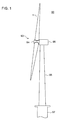
- FIG. 1 is a schematic configuration diagram of a wind turbine power generating apparatus according to an embodiment.
- FIG. 2 is a perspective view of a wind turbine blade according to an embodiment.
- a wind turbine power generating apparatus 90 includes a rotor 93 including at least one (e.g. three) wind turbine blades 1 and a hub 94.
- the wind turbine blades 1 are mounted to the hub 94 in a radial fashion, the rotor 93 rotates in response to wind received by the wind turbine blades 1, and a generator (not depicted) coupled to the rotor 93 generates electric power.
- the rotor 93 is supported by a nacelle 95 disposed on an upper part of a tower 96.
- the tower 96 is disposed to stand upright on a base structure 97 (e.g. foundation structure or floating structure) disposed onshore or offshore.
- vortex generators according to an embodiment is mounted to the wind turbine blades 1 of the wind turbine power generating apparatus 90.
- the wind turbine blade 1 includes a blade body 2 and a vortex generator 10 mounted to a surface (blade surface) of the blade body 2.
- the blade body 2 includes a blade root 3 to be attached to the hub 94 of the wind turbine power generating apparatus 90, a blade tip 4 positioned farthest from the hub 94, and an airfoil part 5 extending between the blade root 3 and the blade tip 4.
- the wind turbine blade 1 has a leading edge 6 and a trailing edge 7 from the blade root 3 to the blade tip 4. Further, an exterior shape of the wind turbine blade 1 is formed by a pressure surface 8 and a suction surface 9 disposed opposite to the pressure surface 8.
- a plurality of the vortex generators 10 is mounted to the suction surface 9 of the blade body 2. More specifically, the plurality of vortex generators 10 is mounted to the suction surface 9 of the blade body 2 in a blade spanwise direction.
- blade spanwise direction refers to a direction connecting the blade root 3 and the blade tip 4
- blade chordwise direction refers to a direction along a line (chord) connecting the leading edge 6 and the trailing edge 7 of the blade body 2.
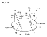
- FIGs. 3A and 4A are each a perspective view of the vortex generator 10 according to an embodiment
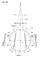
- FIGs. 3B and 4B are each a top view of the vortex generator 10 depicted in FIGs. 3A and 4A , respectively.
- FIGs. 5 to 7 are each a top view of the vortex generator 10 according to an embodiment.
- the vortex generator 10 includes a platform portion 11 to be fixed to a surface of the wind turbine blade 1 (more specifically, to a surface of the blade body 2) and at least one fin 12 disposed upright on the platform portion 11.
- the vortex generator 10 includes a pair (two in total) of fins 12 (12A, 12B) disposed so as to be adjacent to each other on the platform portion 11.
- the vortex generator 10 includes two pairs (four in total) of fins 12 (12A, 12B) disposed so as to be adjacent to each other on the platform portion 11.
- the platform portion 11 has a circular shape in a top view.
- the platform portion 11 has a trapezoidal shape in a top view.
- the platform portion 11 may have a shape other than a circle or a trapezoid.
- the platform portion 11 may have an oval shape as depicted in FIG. 6 , or may have a polygonal shape such as a rectangular shape, or another shape.
- the fin 12 has an airfoil shape.
- the fin 12 includes a leading edge 13 disposed on an upstream side with respect to the inflow direction of wind, a trailing edge 14 disposed on a downstream side with respect to the inflow direction of wind, a pressure surface 15 of the fin 12 facing toward upstream with respect to the inflow direction of wind, and a suction surface 16 of the fin 12 facing toward downstream with respect to the inflow direction of wind.
- the direction of a line connecting the leading edge 13 and the trailing edge 14 is the chordwise direction of the fin 12.
- the fin 12 is disposed inclined from the inflow direction of wind at a predetermined angle.
- each of the fins 12A, 12B is disposed so that a gap between the pair of fins 12A, 12B widens from upstream toward downstream with respect to the inflow direction of wind (i.e., from the side of the leading edge 6 toward the side of the trailing edge 7 of the wind turbine blade 1 (see FIG. 2 )).
- each of the fins 12A, 12B may be disposed so that a gap between the pair of fins 12A, 12B widens from downstream toward upstream with respect to the inflow direction of wind (i.e., from the side of the trailing edge 7 toward the side of the leading edge 6 of the wind turbine blade 1 (see FIG. 2 )).
- the vortex generator 10 mounted to the wind turbine blade 1 normally generates a longitudinal vortex on the side of the suction surface 16 of the fin 12 with a lift produced by the fin 12. Further, in response to a flow flowing into the fin 12, a longitudinal vortex is generated along an edge extending from the upstream-most position 13a toward the top portion 13b of the leading edge 13 of the fin 12.
- the longitudinal vortices generated by the fin 12 promote momentum exchange between outside and inside of a boundary layer on a surface of the wind turbine blade 1, in a height direction of the fin 12, at a downstream side of the vortex generator 10. Accordingly, the boundary layer on the surface of the wind turbine blade 1 reduces in thickness, and thereby trailing-edge separation of the wind turbine blade 1 is suppressed.
- the vortex generator 10 is disposed within a turbulent flow region of a wind flow along the suction surface 9, on the suction surface 9 of the blade body 2. As described above, the vortex generator 10 is disposed within a turbulent flow region of a wind flow along the suction surface 9, and thereby it is possible to suppress separation of a flow from the suction surface 9.
- the platform portion 11 has marks 20 which indicate orientation of the vortex generator, disposed on at least a pair of opposite positions in an outer edge region of the platform portion 11.
- the outer edge region of the platform portion 11 is a peripheral region of the contour of the platform portion in a planar view.
- the outer edge region of the platform portion 11 is, for instance, the peripheral region of the contour of the circular shape of the platform portion 11 in the example depicted in FIGs. 3A and 3B , and the peripheral region of the contour of the trapezoidal shape of the platform portion 11 in the example depicted in FIGs. 4A and 4B .
- a pair of opposite positions in the outer edge region of the platform portion 11 is a pair of positions facing each other across an inner region surrounded by the outer edge region, the positions being disposed within the outer edge region of the platform portion 11.
- the pair of the mark 20A and the mark 20A', and the pair of the mark 20B and the mark 20B' are each a pair of marks disposed on a pair of opposite positions in the outer edge region of the platform portion 11.
- the marks 20 disposed on a pair of opposite positions in the outer edge region of the platform portion 11 indirectly indicate the orientation of the fin 12 on the platform portion 11, and thus indicate the orientation of the vortex generator 10.
- wind normally flows into the wind turbine power generating apparatus 90 from the leading edge 6 toward the trailing edge 7 of the wind turbine blade 1.
- a reference direction that serves as a reference of a mounting direction of the vortex generator 10
- adjusting a mounting angle of the vortex generator 10 so that a direction indicated by the marks 20 of the vortex generator 10 forms a predetermined angle with the reference direction
- a suitable mounting direction of the vortex generator 10 on the wind turbine blade 1 can be determined on the basis of fluid analysis, for instance. Furthermore, a predetermined angle formed between the marks 20 of each vortex generator 10 and the reference direction on the wind turbine blade 1 can be determined on the basis of the reference direction defined for the wind turbine blade 1 and a suitable mounting direction determined in advance by fluid analysis or the like.
- the mark 20 may be a pair of marks formed on a pair of opposite positions, respectively, in the outer edge region of the platform portion 11 as depicted in FIGs. 3A to 4B , 6 , and 7 .
- the mark 20 may be provided as a mark 20 of a linear shape connecting marks 20A, 20A' at a pair of opposite positions in the outer edge region of the platform portion 11 as depicted in FIG. 5 .
- the platform portion 11 has a circular shape in a top view, and a line connecting a pair of opposite positions at which the marks 20 are formed passes through the center of the circular shape of the platform portion 11.
- a line L A connecting a pair of opposite positions at which the mark 20A and the mark 20A' are respectively provided passes through the center C of the circular shape of the platform portion 11.
- a line L B connecting a pair of opposite positions at which the mark 20B and the mark 20B' are respectively provided passes through the center C of the circular shape of the platform portion 11.
- a line e.g. L A or L B depicted in FIGs. 3B and 7
- a line that connects a pair of opposite positions at which the marks 20 are respectively formed on the platform portion 11 having a circular shape in a top view passing through the center C of the platform portion 11
- the pair of fins 12 (12A, 12B) disposed adjacent to each other on the platform portion 11 is oriented so that respective chordwise directions of the fins 12 intersect with each other.
- the pair of fins 12 (12A, 12B) is disposed on the platform portion 11 so that respective lines connecting the leading edge 13 and the trailing edge 14 of the fins 12A, 12B (lines L C1 , L C2 extending in respective chordwise directions) intersect with each other at an intersection I.
- the marks 20 disposed on the platform portion 11 include a reference mark (first reference mark) 24 and a reference mark (second reference mark) 26.
- the reference mark (first reference mark) 24 is the mark 20 disposed on a line which connects a pair of opposite positions (positions of a pair of marks 20 facing each other) passing through the center C of the circular shape of the platform portion 11, and which is orthogonal to a bisector L H (see FIG. 3B ) of an angle formed by chordwise directions of the two fins 12 (12A, 12B).
- the reference mark (second reference mark) 26 is the mark 20 disposed on a line which connects a pair of opposite positions (positions of a pair of marks 20 facing each other) passing through the center C of the circular shape of the platform portion 11, and which is parallel to a bisector L H of an angle formed by chordwise directions of the two fins 12 (12A, 12B).
- the line L A connecting a pair of opposite positions at which the mark 20A and the mark 20A' are respectively disposed is a line which passes through the center C of the circular shape of the platform portion 11, and which is orthogonal to the bisector L H of an angle formed by chordwise directions of the two fins 12 (12A, 12B) (an angle formed by lines L C1 , L C2 extending in respective chordwise directions).
- the mark 20A and the mark 20A' are each a reference mark (first reference mark) 24 disposed on the line L A .
- the line L B connecting a pair of opposite positions at which the mark 20B and the mark 20B' are respectively disposed is a line which passes through the center C of the circular shape of the platform portion 11, and which is parallel to the bisector L H of an angle formed by chordwise directions of the two fins 12 (12A, 12B) (an angle formed by lines L C1 , L C2 extending in respective chordwise directions). Furthermore, the mark 20B and the mark 20B' are each a reference mark (second reference mark) 26 disposed on the line L B .
- the platform portion 11 of a circular shape includes a reference mark (first reference mark) 24 and a reference mark (second reference mark) 26.
- the reference mark (first reference mark) 24 and the reference mark (second reference mark) 26 are disposed on lines (lines L A , L B in FIG. 3B ) passing through the center C of the circular shape of the platform portion 11 and extending orthogonal to each other, and thereby it is possible to match the position of the center C of the circular shape of the platform portion 11, which is an intersection of the lines L A , L B , with the mounting position of the vortex generator 10 with high accuracy. Accordingly, with the platform portion 11 having the reference mark (first reference mark) 24 and the reference mark (second reference mark) 26, it is possible to position the vortex generator 10 at the mounting position on the wind turbine blade 1 with high accuracy.
- the platform portion 11 includes the reference mark 24 and an angle-indicating mark 25 (25A, 25B).
- the reference mark 24 is a mark 20 formed along a reference line L R orthogonal to a bisector L H of an angle formed by chordwise directions of the two fins 12 (12A, 12B).
- the reference line L R is a line passing through the center C of the circular shape of the platform portion 11, and is the same line as the line L A connecting the pair of opposite positions at which the mark 20A and the mark 20A' are respectively disposed.
- the platform portion 11 has a circular shape and thus the reference mark 24 is equivalent to the first reference mark 24 described above, and thus is associated with the same reference numeral.
- the angle-indicating mark 25 is a mark 20 formed along a line forming a predetermined angle ⁇ with the reference line L R .
- the platform portion 11 includes a plurality of angle-indicating marks 25 disposed along respective lines which form different angles with the reference line L R (herein, angles about the center C of the circular shape of the platform portion 11).
- angle-indicating marks 25 corresponding to a plurality of determined angles ⁇ are formed on the platform portion 11.
- the plurality of angle-indicating marks 25 are disposed at regular angular intervals.
- the vortex generator 10 With the plurality of angle-indicating marks 25 formed on the platform portion 11 as described above, it is possible to mount the vortex generator 10 in a suitable mounting direction (at a mounting angle ⁇ ) with respect to the inflow direction of wind with high accuracy, by selecting the angle-indicating mark 25 forming a desired angle ⁇ with the reference line L R from among the plurality of angle-indicating marks 25, and aligning the angle-indicating mark 25 in the reference direction on the wind turbine blade 1.
- At least one of the plurality of angle-indicating marks 25 is different in length or thickness from the reference mark 24 and the other angle-indicating marks 25.
- the relatively-longer angle-indicating marks 25 and the relatively-shorter angle-indicating marks 25 may be disposed alternately.
- the marks 20 are recessed from the peripheral portion of the mark 20 on the platform portion 11.
- the marks 20 may be formed on the platform portion 11 as grooves recessed from the surface of the platform portion 11.
- the surface of the platform portion 11 of the vortex generator 10 becomes smooth as a result of another substance (e.g. sealant or putty) filling the recess corresponding to the marks 20 on the platform portion 11 during mounting of the vortex generator 10, or another substance (e.g. suspended matters in atmosphere) accumulating in the recess corresponding to the marks 20 during operation of the wind turbine power generating apparatus 90. Accordingly, during operation of the wind turbine power generating apparatus 90 with the vortex generator 10 mounted to the wind turbine blade 1, it is possible to reduce an influence from the marks 20 on a wind flow that the wind turbine blade 1 receives.
- another substance e.g. sealant or putty
- angle-indicating marks 25 may be disposed in the vicinity of the pair of reference marks (first reference marks) 24 (marks 20A, 20A') as depicted in FIG. 7 .
- the angle-indicating marks 25 may be disposed in the vicinity of the pair of reference marks (second reference marks) 26 (marks 20B, 20B').
- angle-indicating marks 25 may be disposed in the vicinity of either one mark 20 of the pair of opposite reference marks 24 (marks 20A, 20A'), or one mark 20 of the pair of opposite reference marks 26 (20B, 20B').
- the pressure surface 15 and the suction surface 16 of the fin 12 have a draft in the height direction based on the platform portion 11.
- FIG. 8 is a cross-sectional view of the vortex generator 10 taken along line VIII-VIII in FIG. 3B .
- the angles of the pressure surface 15 and the suction surface 16 are inclined by angular degrees ⁇ 1 , ⁇ 2 , respectively, from the height direction based on the platform portion 11 (a direction perpendicular to the platform portion 11), so that the thickness of the fin 12 reduces gradually toward a top portion 18 from a root portion 17 of the fin 12, at the trailing edge 14 of the fin 12.
- the pressure surface 15 and the suction surface 16 of the fin 12 have a draft in the height direction based on the platform portion 11, and thus the vortex generator 10 can be easily removed from a mold during production of the vortex generator 10 by molding.
- FIGs. 9 to 12 are each a diagram for describing a method of mounting the vortex generator 10.
- vortex generator 10 is mounted to the suction surface 9 of the wind turbine blade 1 (blade body 2) in the following description as an example, the vortex generator 10 can be mounted to the pressure surface 8 of the wind turbine blade 1 by a similar method.
- the positions of reference points P 1 and P 2 are specified on the blade surface (suction surface 9) of the wind turbine blade 1.
- a reference point is a point for determining a reference direction which serves as a reference of a mounting direction of the vortex generator 10.
- the positions of the two reference points P 1 , P 2 on the blade surface of the wind turbine blade 1 are, for instance, specified on the basis of the mounting position of the vortex generator 10 determined in advance by fluid analysis or the like.
- a reference point can be, for instance, represented by coordinates (z, l) in the blade spanwise direction and the chordwise direction on the blade surface of the wind turbine blade 1.
- the coordinates of the reference points P 1 and P 2 determined in advance are represented by P 1 (z 1 , l 1 ) and P 2 (z 2 , l 2 ), respectively.
- the positions corresponding to l coordinates (i.e., l 1 and l 2 ) of the reference points P 1 and P 2 can be specified on the blade surface by measuring the lengths from a blade spanwise directional line Ls along the blade spanwise direction on the blade surface.
- the blade spanwise directional line Ls is a line extending in the blade spanwise direction at a position between the leading edge 6 and the trailing edge 7 in the chord direction on the blade surface (suction surface 9).
- the line Ls can be drawn with reference to the position of a member (e.g. receptor) mounted to a specific position on the blade surface, for instance.
- the trailing edge 7 of the wind turbine blade 1 may be used as the blade longitudinal directional line Ls.
- the positions corresponding to z coordinates (i.e. z 1 and z 2 ) of the reference points P 1 and P 2 can be specified on the blade surface by measuring a distance from the blade root 3 with reference to the blade root 3 by laser measurement or the like.
- the vortex generator 10 is mounted to the wind turbine blade 1, so that the marks 20 representing orientation of the vortex generator 10 are disposed on the line L ref connecting the reference points P 1 and P 2 .
- the line L ref connecting the reference points P 1 and P 2 is a line representing a reference direction during mounting of the vortex generator 10 to the wind turbine blade 1.
- the line L ref may be displayed on the blade surface of the wind turbine blade 1 visually by using a tape or a pen, or by marking off, for instance.
- the marks 20 disposed on the line L ref during mounting of the vortex generator 10 may be the reference marks 24, or the angle-indicating marks 25.
- the vortex generator 10 having the reference marks 24 and the angle-indicating marks 25 is mounted to the wind turbine blade 1 so that the angle-indicating marks 25 are disposed on the line L ref .
- the vortex generator 10 is located on the surface of the wind turbine blade 1 in such a way that the pair of reference marks 24 is aligned along the line L ref .
- the vortex generator 10 is located in such a way that a reference point (e.g. the center C of the platform portion 11 having a circular shape) of the vortex generator 10 is at a predetermined mounting position in the blade spanwise direction.
- the mounting position of the vortex generator 10 in the blade spanwise direction may be determined in advance on the basis of fluid analysis or the like.
- the mounting position of the vortex generator 10 in the blade spanwise direction may be the same as the reference point P 1 or the reference point P 2 .
- FIG. 11A depicted is the vortex generator 10 located on the blade surface of the wind turbine blade 1 as described above.
- the mounting angle of the vortex generator 10 is adjusted by revolving the vortex generator 10 about the center C by a predetermined mounting angle ⁇ .
- the vortex generator 10 is rotated about the center C so that the angle-indicating marks 25, which form an angle ⁇ with the direction indicated by the reference marks 24, is aligned along the line L ref .
- the predetermined mounting angle ⁇ may be determined in advance on the basis of fluid analysis or the like.
- the mounting position and the mounting angle of the vortex generator 10 on the wind turbine blade 1 are adjusted as described above, and then the vortex generator 10 is fixed to the wind turbine blade 1.
- the vortex generator 10 may be fixed to the wind turbine blade 1 by using an adhesive agent or a double-sided adhesive tape.
- a plurality of the vortex generators 10 may be mounted to the wind turbine blade 1 with reference to the single line L ref drawn on the wind turbine blade 1. With the plurality of vortex generators 10 mounted to the wind turbine blade 1 with reference to the single line L ref as described above, it is possible to mount the wind turbine blade 1 efficiently to the vortex generator 10.
- the vortex generator 10 mounted to the wind turbine blade 1 in such a way that the marks 20 indicating orientation of the vortex generator 10 are disposed on the line L ref connecting the reference points P 1 and P 2 specified on the wind turbine blade 1, it is possible to mount the vortex generator 10 to the wind turbine blade 1 in a suitable mounting direction with respect to an inflow direction of wind.
- an expression of relative or absolute arrangement such as “in a direction”, “along a direction”, “parallel”, “orthogonal”, “centered”, “concentric” and “coaxial” shall not be construed as indicating only the arrangement in a strict literal sense, but also includes a state where the arrangement is relatively displaced by a tolerance, or by an angle or a distance whereby it is possible to achieve the same function.
- an expression of an equal state such as “same” “equal” and “uniform” shall not be construed as indicating only the state in which the feature is strictly equal, but also includes a state in which there is a tolerance or a difference that can still achieve the same function.
- an expression of a shape such as a rectangular shape or a cylindrical shape shall not be construed as only the geometrically strict shape, but also includes a shape with unevenness or chamfered corners within the range in which the same effect can be achieved.
Abstract
Description
- The present disclosure relates to a vortex generator for a wind turbine blade, a wind turbine blade, a wind turbine power generating apparatus, and a method of mounting a vortex generator.
- Approaches to improve aerodynamic performance of a wind turbine blade have been sought for some time in context of improvement of operation efficiency of a wind turbine. In one of the approaches, a vortex generator is disposed on a surface of a wind turbine blade to suppress separation of a flow along the surface of the wind turbine blade.
-
Patent Documents 1 to 10 disclose a vortex generator having a platform portion to be mounted to a surface of a wind turbine blade, and a fin disposed upright on the platform portion. -
- Patent Document 1:
US Patent Application Publication No. 2014/0140856 - Patent Document 2:
EP2548800A - Patent Document 3:
EP2799709A - Patent Document 4:
WO2007/140771A - Patent Document 5:
EP2484895A - Patent Document 6:
EP2484896A - Patent Document 7:
EP2484897A - Patent Document 8:
EP2484898A - Patent Document 9:
WO2015/030573A - Patent Document 10:
EP2597300A - If a mounting direction of a vortex generator with respect to an inflow direction of wind is not a suitable direction, generation of vortices by the vortex generator may become unstable, which may lead to insufficient improvement of the aerodynamic performance of a wind turbine blade, or even to a decrease in the aerodynamic performance of a wind turbine blade. Thus, it is desirable to mount a vortex generator to a wind turbine blade so that the vortex generator forms a predetermined mounting angle with the wind turbine blade.
- However,
Patent Documents 1 to 10 do not disclose any specific configuration of a vortex generator for mounting a vortex generator to a wind turbine blade accurately at a predetermined mounting angle. - In view of the above, an object of at least one embodiment of the present invention is to provide a vortex generator which is mountable to a wind turbine blade in a suitable mounting direction with respect to an inflow direction of wind.
- (1) A vortex generator for a wind turbine blade according to at least one embodiment of the present invention comprises: a platform portion to be fixed to a surface of the wind turbine blade; and at least one fin erected on the platform portion. The platform portion includes marks disposed on a pair of opposite positions in an outer edge region of the platform portion and indicating orientation of the vortex generator.
With the above configuration (1), the vortex generator has marks disposed on at least a pair of opposite positions in an outer edge region of the platform portion, the marks indicating orientation of the vortex generator. Thus, by adjusting a mounting angle of the vortex generator so that the marks of the vortex generator form a predetermined angle with a reference direction on the wind turbine blade, it is possible to mount the vortex generator to the wind turbine blade in a suitable mounting direction with respect to an inflow direction of wind. - (2) In some embodiments, in the above configuration (1), the platform portion has a circular shape in a top view, and a line connecting the pair of opposite positions passes through a center of the circular shape of the platform portion.
With the above configuration (2), the platform portion of the vortex generator has a circular shape in a top view, and a line that connects a pair of opposite positions of the marks passes through the center of the platform portion, and thereby it is possible to specify the center position of the circular shape of the platform portion in a direction orthogonal to the line on a blade surface of the wind turbine blade. Thus, it is possible to position the vortex generator at the mounting position on the wind turbine blade by making use of the marks on the platform portion. - (3) In some embodiments, in the above configuration (2), the at least one fin comprises two fins disposed adjacent to each other on the platform portion and oriented so that chordwise directions of the two fins intersect with each other. The marks comprise: a first reference mark disposed on a line which connects the pair of opposite positions and passes through the center of the circular shape of the platform portion, and which is orthogonal to a bisector of an angle formed by the chordwise directions of the two fins; and a second reference mark disposed on a line which connects the pair of opposite positions and passes through the center of the circular shape of the platform portion, and which is parallel to the bisector of the angle formed by the chordwise directions of the two fins.
With the above configuration (3), the first reference mark and the second reference mark are disposed on lines passing through the center of the circular shape of the platform portion and extending orthogonal to each other, and thereby it is possible to match the position of the center of the circular shape of the platform portion, which is an intersection of the lines, with the mounting position of the vortex generator accurately. Thus, it is possible to position the vortex generator at the mounting position on the wind turbine blade accurately. - (4) In some embodiments, in any one of the above configurations (1) to (3), the at least one fin comprises two fins disposed adjacent to each other on the platform portion, and oriented so that chordwise directions of the two fins intersect with each other. The marks comprise: a reference mark formed along a reference line orthogonal to a bisector of an angle formed by the chordwise directions of the two fins; and an angle-indicating mark formed along a line forming a predetermined angle with the reference line.
With the above configuration (4), the vortex generator has an angle-indicating mark formed along a line forming a predetermined angle α with the reference line defining a direction indicated by the reference mark, and thereby it is possible to mount the vortex generator to the wind turbine blade at a mounting angle α with high accuracy by aligning the angle-indicating mark along the reference direction on the wind turbine blade. Accordingly, with the above configuration (4), the angle-indicating mark is disposed so as to form a predetermined angle α with the reference line, and thereby it is possible to mount the vortex generator to the wind turbine blade in a suitable mounting direction (at a mounting angle α) with respect to an inflow direction of wind with high accuracy, merely by aligning the angle-indicating mark along the reference direction on the wind turbine blade. - (5) In some embodiments, in the above configuration (4), the angle-indicating mark comprises a plurality of angle-indicating marks formed along a plurality of lines forming different angles with the reference line, respectively, and at least one of the angle-indicating marks is different in length or thickness from the reference mark and the other angle-indicating marks.
- With the above configuration (5), the vortex generator includes a plurality of angle-indicating marks formed along respective lines forming different angles with the reference line defining the direction indicated by the reference mark. Accordingly, it is possible to mount the vortex generator in a suitable mounting direction (at a mounting angle α) with respect to an inflow direction of wind with high accuracy, by selecting the angle-indicating mark forming a desired angle α with the reference line from among the plurality of angle-indicating marks, and aligning the selected angle-indicating mark along the reference direction on the wind turbine blade.
- Furthermore, with the above configuration (5), at least one of the plurality of angle-indicating marks is different in length or thickness from the reference mark and the other angle-indicating marks, and thereby it is possible to read the angular degree indicated by each respective angle-indicating mark accurately and readily.
- (6) In some embodiments, in any one of the above configurations (1) to (5), the marks are recessed from a portion, around the marks, of the platform portion.
- With the above configuration (6), the marks of the vortex generator are recessed from the portion around the marks of the platform portion, and thus the surface of the platform portion of the vortex generator becomes smooth as a result of another substance (e.g. sealant or putty) filling the recess during mounting of the vortex generator, or another substance (e.g. suspended matters in atmosphere) accumulating in the recess during operation of the wind turbine. Accordingly, during operation of the wind turbine with the vortex generator mounted to the wind turbine blade, it is possible to mitigate an influence of the marks on a wind flow that the wind turbine blade receives.
- In some embodiments, in any one of the above configurations (1) to (6), a pressure surface and a suction surface of the fin have a draft in a height direction based on the platform portion.
- With the above configuration (7), the pressure surface and the suction surface of the fin have a draft in the height direction based on the platform portion, and thus the vortex generator can be easily removed from a mold during production of the vortex generator by molding.
- (8) A wind turbine blade according to at least one embodiment of the present invention comprises: a blade body; and the vortex generator according to any one of the above (1) to (7), mounted to a surface of the blade body.
With the above configuration (8), the vortex generator has marks disposed on at least a pair of opposite positions in an outer edge region of the platform portion, the marks indicating orientation of the vortex generator. Thus, by adjusting a mounting angle of the vortex generator so that the marks of the vortex generator form a predetermined angle with a reference direction on the wind turbine blade, it is possible to mount the vortex generator to the wind turbine blade in a suitable mounting direction with respect to an inflow direction of wind. - (9) In some embodiments, in the above configuration (8), the vortex generator is disposed on a suction surface of the blade body and within a turbulence region of a wind flow along the suction surface.
- Separation of a flow at the suction surface of the wind turbine blade takes place due to a boundary layer becoming gradually thicker from a streamline flow region in the vicinity of the leading edge toward a turbulent flow region downstream thereof, and the flow being separated before arriving at the trailing edge.
- In this regard, with the above configuration (9), the vortex generator is disposed within a turbulent flow region of a wind flow along the suction surface, and thereby it is possible to suppress separation of a flow from the suction surface.
- (10) A wind turbine power generating apparatus according to at least one embodiment of the present invention comprises the wind turbine blade according to the above (8) or (9).
With the above configuration (10), the vortex generator has marks disposed on at least a pair of opposite positions in an outer edge region of the platform portion, the marks indicating orientation of the vortex generator,. Thus, by adjusting a mounting angle of the vortex generator so that the marks of the vortex generator form a predetermined angle with a reference direction on the wind turbine blade, it is possible to mount the vortex generator to the wind turbine blade in a suitable mounting direction with respect to an inflow direction of wind. - (11) A method of mounting a vortex generator according to at least one embodiment of the present invention comprises: a step of specifying positions of at least two reference points on a wind turbine blade; and a step of mounting the vortex generator according to any one of the above (1) to (7) to the wind turbine blade so that the marks of the vortex generator are disposed on a line connecting the reference points.
- In the above method (11), the vortex generator is mounted to the wind turbine blade so that the marks indicating the direction of the vortex generator are disposed on a line connecting at least two reference points specified on the wind turbine blade. Accordingly, it is possible to mount the vortex generator to the wind turbine blade in a suitable mounting direction with respect to an inflow direction of wind.
- According to at least one embodiment of the present invention, provided is a vortex generator which is mountable to a wind turbine blade in a suitable mounting direction with respect to an inflow direction of wind.
-
-
FIG. 1 is a schematic configuration diagram of a wind turbine power generating apparatus according to an embodiment. -
FIG. 2 is a perspective view of a wind turbine blade according to an embodiment. -
FIG. 3A is a perspective view of a vortex generator according to an embodiment. -
FIG. 3B is a top view of a vortex generator depicted inFIG. 3A . -
FIG. 4A is a perspective view of a vortex generator according to an embodiment. -
FIG. 4B is a top view of a vortex generator depicted inFIG. 4A . -
FIG. 5 is a top view of a vortex generator according to an embodiment. -
FIG. 6 is a top view of a vortex generator according to an embodiment. -
FIG. 7 is a top view of a vortex generator according to an embodiment. -
FIG. 8 is a cross-sectional view of a vortex generator taken along line VIII-VIII inFIG. 3B . -
FIG. 9 is a diagram for describing a method of mounting a vortex generator. -
FIG. 10 is a diagram for describing a method of mounting a vortex generator. -
FIG. 11A is a diagram for describing a method of mounting a vortex generator. -
FIG. 11B is a diagram for describing a method of mounting a vortex generator. -
FIG. 12 is a diagram for describing a method of mounting a vortex generator. - Embodiments of the present invention will now be described in detail with reference to the accompanying drawings. It is intended, however, that unless particularly specified, dimensions, materials, shapes, relative positions and the like of components described in the embodiments shall be interpreted as illustrative only and not intended to limit the scope of the present invention.
- With reference to
FIGs. 1 and2 , an overall configuration of a wind turbine blade and a wind turbine power generating apparatus to which a vortex generator according to some embodiments is to be applied will be described.FIG. 1 is a schematic configuration diagram of a wind turbine power generating apparatus according to an embodiment.FIG. 2 is a perspective view of a wind turbine blade according to an embodiment. - As depicted in
FIG. 1 , a wind turbinepower generating apparatus 90 includes arotor 93 including at least one (e.g. three)wind turbine blades 1 and ahub 94. Thewind turbine blades 1 are mounted to thehub 94 in a radial fashion, therotor 93 rotates in response to wind received by thewind turbine blades 1, and a generator (not depicted) coupled to therotor 93 generates electric power. - In the embodiment depicted in
FIG. 1 , therotor 93 is supported by a nacelle 95 disposed on an upper part of atower 96. Thetower 96 is disposed to stand upright on a base structure 97 (e.g. foundation structure or floating structure) disposed onshore or offshore. - As described below, vortex generators according to an embodiment is mounted to the
wind turbine blades 1 of the wind turbinepower generating apparatus 90. - As depicted in
FIG. 2 , thewind turbine blade 1 includes ablade body 2 and avortex generator 10 mounted to a surface (blade surface) of theblade body 2. - The
blade body 2 includes ablade root 3 to be attached to thehub 94 of the wind turbinepower generating apparatus 90, ablade tip 4 positioned farthest from thehub 94, and anairfoil part 5 extending between theblade root 3 and theblade tip 4. Thewind turbine blade 1 has aleading edge 6 and a trailingedge 7 from theblade root 3 to theblade tip 4. Further, an exterior shape of thewind turbine blade 1 is formed by apressure surface 8 and asuction surface 9 disposed opposite to thepressure surface 8. - With regard to the
wind turbine blade 1 depicted inFIG. 2 , a plurality of thevortex generators 10 is mounted to thesuction surface 9 of theblade body 2. More specifically, the plurality ofvortex generators 10 is mounted to thesuction surface 9 of theblade body 2 in a blade spanwise direction. - In the present specification, "blade spanwise direction" refers to a direction connecting the
blade root 3 and theblade tip 4, and "blade chordwise direction" refers to a direction along a line (chord) connecting theleading edge 6 and the trailingedge 7 of theblade body 2. - Next, a vortex generator according to some embodiments will be described in detail with reference to
FIGs. 3A to 7 . -
FIGs. 3A and4A are each a perspective view of thevortex generator 10 according to an embodiment, andFIGs. 3B and4B are each a top view of thevortex generator 10 depicted inFIGs. 3A and4A , respectively.FIGs. 5 to 7 are each a top view of thevortex generator 10 according to an embodiment. - The
vortex generator 10 includes aplatform portion 11 to be fixed to a surface of the wind turbine blade 1 (more specifically, to a surface of the blade body 2) and at least onefin 12 disposed upright on theplatform portion 11. In the embodiment depicted inFIGs. 3A to 5 , and7 , thevortex generator 10 includes a pair (two in total) of fins 12 (12A, 12B) disposed so as to be adjacent to each other on theplatform portion 11. Furthermore, in the embodiment depicted inFIG. 6 , thevortex generator 10 includes two pairs (four in total) of fins 12 (12A, 12B) disposed so as to be adjacent to each other on theplatform portion 11. - In the embodiment depicted in
FIGs. 3A ,3B ,5 , and7 , theplatform portion 11 has a circular shape in a top view. In the embodiment depicted inFIGs. 4A and 4B , theplatform portion 11 has a trapezoidal shape in a top view.
In some embodiments, theplatform portion 11 may have a shape other than a circle or a trapezoid. For instance, theplatform portion 11 may have an oval shape as depicted inFIG. 6 , or may have a polygonal shape such as a rectangular shape, or another shape. - In an embodiment illustrated in
FIGs. 3A to 7 , thefin 12 has an airfoil shape. Thefin 12 includes aleading edge 13 disposed on an upstream side with respect to the inflow direction of wind, a trailingedge 14 disposed on a downstream side with respect to the inflow direction of wind, apressure surface 15 of thefin 12 facing toward upstream with respect to the inflow direction of wind, and asuction surface 16 of thefin 12 facing toward downstream with respect to the inflow direction of wind. In thisfin 12, the direction of a line connecting the leadingedge 13 and the trailingedge 14 is the chordwise direction of thefin 12. - In some embodiments, the
fin 12 is disposed inclined from the inflow direction of wind at a predetermined angle. - For instance, in the
vortex generator 10 depicted inFIGs. 3A to 7 , each of thefins fins leading edge 6 toward the side of the trailingedge 7 of the wind turbine blade 1 (seeFIG. 2 )). - In some embodiments, each of the
fins fins edge 7 toward the side of theleading edge 6 of the wind turbine blade 1 (seeFIG. 2 )). - A function of the
vortex generator 10 will now be described briefly. - Separation of a flow at the
suction surface 9 of thewind turbine blade 1 takes place due to a boundary layer becoming gradually thicker from a streamline flow region in the vicinity of theleading edge 6 toward a turbulent flow region downstream thereof, and the flow being separated before arriving at the trailingedge 7. - The
vortex generator 10 mounted to thewind turbine blade 1 normally generates a longitudinal vortex on the side of thesuction surface 16 of thefin 12 with a lift produced by thefin 12. Further, in response to a flow flowing into thefin 12, a longitudinal vortex is generated along an edge extending from theupstream-most position 13a toward thetop portion 13b of the leadingedge 13 of thefin 12. The longitudinal vortices generated by thefin 12 promote momentum exchange between outside and inside of a boundary layer on a surface of thewind turbine blade 1, in a height direction of thefin 12, at a downstream side of thevortex generator 10. Accordingly, the boundary layer on the surface of thewind turbine blade 1 reduces in thickness, and thereby trailing-edge separation of thewind turbine blade 1 is suppressed. - In some embodiments, the
vortex generator 10 is disposed within a turbulent flow region of a wind flow along thesuction surface 9, on thesuction surface 9 of theblade body 2. As described above, thevortex generator 10 is disposed within a turbulent flow region of a wind flow along thesuction surface 9, and thereby it is possible to suppress separation of a flow from thesuction surface 9. - In the embodiment depicted in
FIGs. 3A to 7 , theplatform portion 11 hasmarks 20 which indicate orientation of the vortex generator, disposed on at least a pair of opposite positions in an outer edge region of theplatform portion 11. - The outer edge region of the
platform portion 11 is a peripheral region of the contour of the platform portion in a planar view. The outer edge region of theplatform portion 11 is, for instance, the peripheral region of the contour of the circular shape of theplatform portion 11 in the example depicted inFIGs. 3A and3B , and the peripheral region of the contour of the trapezoidal shape of theplatform portion 11 in the example depicted inFIGs. 4A and 4B . - Furthermore, a pair of opposite positions in the outer edge region of the
platform portion 11 is a pair of positions facing each other across an inner region surrounded by the outer edge region, the positions being disposed within the outer edge region of theplatform portion 11. For instance, inFIGs. 3A to 7 , the pair of themark 20A and themark 20A', and the pair of themark 20B and themark 20B', are each a pair of marks disposed on a pair of opposite positions in the outer edge region of theplatform portion 11. - A direction indicated by the
marks 20 disposed on a pair of opposite positions in the outer edge region of theplatform portion 11, which is a direction of a line mutually connecting the pair of opposite directions, forms a particular angle with the orientation (installation direction) of thefin 12 on theplatform portion 11. Thus, themarks 20 disposed on a pair of opposite positions in the outer edge region of theplatform portion 11 indirectly indicate the orientation of thefin 12 on theplatform portion 11, and thus indicate the orientation of thevortex generator 10. - During operation, wind normally flows into the wind turbine
power generating apparatus 90 from theleading edge 6 toward the trailingedge 7 of thewind turbine blade 1. Thus, for thewind turbine blade 1, by defining in advance a reference direction that serves as a reference of a mounting direction of thevortex generator 10, and adjusting a mounting angle of thevortex generator 10 so that a direction indicated by themarks 20 of thevortex generator 10 forms a predetermined angle with the reference direction, it is possible to mount thevortex generator 10 to thewind turbine blade 1 in a suitable mounting direction with respect to the inflow direction of wind. - A suitable mounting direction of the
vortex generator 10 on thewind turbine blade 1 can be determined on the basis of fluid analysis, for instance. Furthermore, a predetermined angle formed between themarks 20 of eachvortex generator 10 and the reference direction on thewind turbine blade 1 can be determined on the basis of the reference direction defined for thewind turbine blade 1 and a suitable mounting direction determined in advance by fluid analysis or the like. - The
mark 20 may be a pair of marks formed on a pair of opposite positions, respectively, in the outer edge region of theplatform portion 11 as depicted inFIGs. 3A to 4B ,6 , and7 . Alternatively, themark 20 may be provided as amark 20 of a linearshape connecting marks platform portion 11 as depicted inFIG. 5 . - In some embodiments, the
platform portion 11 has a circular shape in a top view, and a line connecting a pair of opposite positions at which themarks 20 are formed passes through the center of the circular shape of theplatform portion 11. - For instance, in the embodiment depicted in
FIGs. 3A ,3B , and7 , a line LA connecting a pair of opposite positions at which themark 20A and themark 20A' are respectively provided passes through the center C of the circular shape of theplatform portion 11. Furthermore, in the embodiment, a line LB connecting a pair of opposite positions at which themark 20B and themark 20B' are respectively provided passes through the center C of the circular shape of theplatform portion 11. - Accordingly, with a line (e.g. LA or LB depicted in
FIGs. 3B and7 ) that connects a pair of opposite positions at which themarks 20 are respectively formed on theplatform portion 11 having a circular shape in a top view passing through the center C of theplatform portion 11, it is possible to specify the center position of the circular shape of theplatform portion 11 in a direction orthogonal to the line on a blade surface of thewind turbine blade 1. Thus, it is possible to position thevortex generator 10 at the mounting position on thewind turbine blade 1, by making use of themarks 20 on theplatform portion 11. - In the embodiment depicted in
FIGs. 3A to 7 , the pair of fins 12 (12A, 12B) disposed adjacent to each other on theplatform portion 11 is oriented so that respective chordwise directions of thefins 12 intersect with each other. For instance, with reference toFIG. 3B , the pair of fins 12 (12A, 12B) is disposed on theplatform portion 11 so that respective lines connecting the leadingedge 13 and the trailingedge 14 of thefins - In an embodiment depicted in
FIGs. 3A ,3B , and7 , themarks 20 disposed on theplatform portion 11 include a reference mark (first reference mark) 24 and a reference mark (second reference mark) 26. - Herein, the reference mark (first reference mark) 24 is the
mark 20 disposed on a line which connects a pair of opposite positions (positions of a pair ofmarks 20 facing each other) passing through the center C of the circular shape of theplatform portion 11, and which is orthogonal to a bisector LH (seeFIG. 3B ) of an angle formed by chordwise directions of the two fins 12 (12A, 12B). Furthermore, the reference mark (second reference mark) 26 is themark 20 disposed on a line which connects a pair of opposite positions (positions of a pair ofmarks 20 facing each other) passing through the center C of the circular shape of theplatform portion 11, and which is parallel to a bisector LH of an angle formed by chordwise directions of the two fins 12 (12A, 12B). - Describing with reference to
FIG. 3B , the line LA connecting a pair of opposite positions at which themark 20A and themark 20A' are respectively disposed is a line which passes through the center C of the circular shape of theplatform portion 11, and which is orthogonal to the bisector LH of an angle formed by chordwise directions of the two fins 12 (12A, 12B) (an angle formed by lines LC1, LC2 extending in respective chordwise directions). Furthermore, themark 20A and themark 20A' are each a reference mark (first reference mark) 24 disposed on the line LA. - The line LB connecting a pair of opposite positions at which the
mark 20B and themark 20B' are respectively disposed is a line which passes through the center C of the circular shape of theplatform portion 11, and which is parallel to the bisector LH of an angle formed by chordwise directions of the two fins 12 (12A, 12B) (an angle formed by lines LC1, LC2 extending in respective chordwise directions). Furthermore, themark 20B and themark 20B' are each a reference mark (second reference mark) 26 disposed on the line LB. - Also in the embodiment depicted in
FIG. 7 , similarly to the embodiment depicted inFIGs. 3A and3B , theplatform portion 11 of a circular shape includes a reference mark (first reference mark) 24 and a reference mark (second reference mark) 26. - The reference mark (first reference mark) 24 and the reference mark (second reference mark) 26 are disposed on lines (lines LA, LB in
FIG. 3B ) passing through the center C of the circular shape of theplatform portion 11 and extending orthogonal to each other, and thereby it is possible to match the position of the center C of the circular shape of theplatform portion 11, which is an intersection of the lines LA, LB, with the mounting position of thevortex generator 10 with high accuracy. Accordingly, with theplatform portion 11 having the reference mark (first reference mark) 24 and the reference mark (second reference mark) 26, it is possible to position thevortex generator 10 at the mounting position on thewind turbine blade 1 with high accuracy. - In the embodiment depicted in
FIG. 7 , theplatform portion 11 includes thereference mark 24 and an angle-indicating mark 25 (25A, 25B). - The
reference mark 24 is amark 20 formed along a reference line LR orthogonal to a bisector LH of an angle formed by chordwise directions of the two fins 12 (12A, 12B). - In the embodiment depicted in
FIG. 7 , the reference line LR is a line passing through the center C of the circular shape of theplatform portion 11, and is the same line as the line LA connecting the pair of opposite positions at which themark 20A and themark 20A' are respectively disposed. Further, in the embodiment depicted inFIG. 7 , theplatform portion 11 has a circular shape and thus thereference mark 24 is equivalent to thefirst reference mark 24 described above, and thus is associated with the same reference numeral. - The angle-indicating
mark 25 is amark 20 formed along a line forming a predetermined angle α with the reference line LR. - With the angle-indicating
mark 25 formed on theplatform portion 11 along a line forming a predetermined angle α with the reference line LR, it is possible to mount thevortex generator 10 to thewind turbine blade 1 at a mounting angle α with high accuracy by aligning the angle-indicatingmark 25 in the reference direction on thewind turbine blade 1. - In the embodiment depicted in
FIG. 7 , theplatform portion 11 includes a plurality of angle-indicatingmarks 25 disposed along respective lines which form different angles with the reference line LR (herein, angles about the center C of the circular shape of the platform portion 11). In other words, angle-indicatingmarks 25 corresponding to a plurality of determined angles α are formed on theplatform portion 11. - In the embodiment depicted in
FIG. 7 , the plurality of angle-indicatingmarks 25 are disposed at regular angular intervals. In other words, the angle-indicatingmarks 25 are each formed along a line which forms a predetermined angle α (angle formed with the reference line LR (angle about the center C of the circular shape of the platform portion 11)) of n×a (n is an integer and a>0°). For instance, if a=1° is satisfied, the angular interval of the angle-indicatingmarks 25 is 1°. - The
reference mark 24 in the embodiment depicted inFIG. 7 is an angle-indicatingmark 25 along a line that forms a predetermined angle α (an angle formed with the reference line LR) of 0° (i.e., an angle in the case of n=0 in the above expression). - With the plurality of angle-indicating
marks 25 formed on theplatform portion 11 as described above, it is possible to mount thevortex generator 10 in a suitable mounting direction (at a mounting angle α) with respect to the inflow direction of wind with high accuracy, by selecting the angle-indicatingmark 25 forming a desired angle α with the reference line LR from among the plurality of angle-indicatingmarks 25, and aligning the angle-indicatingmark 25 in the reference direction on thewind turbine blade 1. - In some embodiments, at least one of the plurality of angle-indicating
marks 25 is different in length or thickness from thereference mark 24 and the other angle-indicatingmarks 25. - For instance, in the embodiment depicted in
FIG. 7 , among the plurality of angle-indicatingmarks 25 formed in the vicinity of thereference mark 24, relatively-longer angle-indicatingmarks 25A (including the reference mark 24) are disposed at intervals of five marks (e.g. if a=1°, at every 5°), while four relatively-shorter angle-indicatingmarks 25B are disposed between adjacent two of the relatively-longer angle-indicatingmarks 25A at intervals of a° (e.g. if a=1°, at every 1 °). - In another embodiment, for instance, the relatively-longer angle-indicating
marks 25 and the relatively-shorter angle-indicatingmarks 25 may be disposed alternately. - As described above, with at least one of the plurality of angle-indicating marks 25 (in
FIG. 7 , the angle-indicatingmarks 25B) being different in length or thickness from thereference mark 24 and the other angle-indicating marks 25 (inFIG. 7 , the angle-indicatingmarks 25A), it is possible to read the angular degree indicated by each angle-indicatingmark 25 accurately and readily. - In some embodiments, the marks 20 (e.g. the reference marks 24, 26 or the angle-indicating marks 25) are recessed from the peripheral portion of the
mark 20 on theplatform portion 11. For instance, as depicted inFIG. 3A , themarks 20 may be formed on theplatform portion 11 as grooves recessed from the surface of theplatform portion 11. - In this case, the surface of the
platform portion 11 of thevortex generator 10 becomes smooth as a result of another substance (e.g. sealant or putty) filling the recess corresponding to themarks 20 on theplatform portion 11 during mounting of thevortex generator 10, or another substance (e.g. suspended matters in atmosphere) accumulating in the recess corresponding to themarks 20 during operation of the wind turbinepower generating apparatus 90. Accordingly, during operation of the wind turbinepower generating apparatus 90 with thevortex generator 10 mounted to thewind turbine blade 1, it is possible to reduce an influence from themarks 20 on a wind flow that thewind turbine blade 1 receives. - Furthermore, the angle-indicating
marks 25 may be disposed in the vicinity of the pair of reference marks (first reference marks) 24 (marks FIG. 7 . Alternatively, the angle-indicatingmarks 25 may be disposed in the vicinity of the pair of reference marks (second reference marks) 26 (marks - Furthermore, the angle-indicating
marks 25 may be disposed in the vicinity of either onemark 20 of the pair of opposite reference marks 24 (marks mark 20 of the pair of opposite reference marks 26 (20B, 20B'). - In some embodiments, the
pressure surface 15 and thesuction surface 16 of thefin 12 have a draft in the height direction based on theplatform portion 11. -
FIG. 8 is a cross-sectional view of thevortex generator 10 taken along line VIII-VIII inFIG. 3B . For instance, as depicted inFIG. 8 , the angles of thepressure surface 15 and thesuction surface 16 are inclined by angular degrees θ1, θ2, respectively, from the height direction based on the platform portion 11 (a direction perpendicular to the platform portion 11), so that the thickness of thefin 12 reduces gradually toward atop portion 18 from aroot portion 17 of thefin 12, at the trailingedge 14 of thefin 12. - As described above, the
pressure surface 15 and thesuction surface 16 of thefin 12 have a draft in the height direction based on theplatform portion 11, and thus thevortex generator 10 can be easily removed from a mold during production of thevortex generator 10 by molding. - Next, a method of mounting the
vortex generator 10 to the wind turbine blade 1 (blade body 2) according to some embodiments will be described in detail with reference toFIGs. 9 to 12. FIGs. 9 to 12 are each a diagram for describing a method of mounting thevortex generator 10. - While the
vortex generator 10 is mounted to thesuction surface 9 of the wind turbine blade 1 (blade body 2) in the following description as an example, thevortex generator 10 can be mounted to thepressure surface 8 of thewind turbine blade 1 by a similar method. - In the method of mounting the
vortex generator 10 according to an embodiment, the positions of reference points P1 and P2 are specified on the blade surface (suction surface 9) of thewind turbine blade 1. - A reference point is a point for determining a reference direction which serves as a reference of a mounting direction of the
vortex generator 10. The positions of the two reference points P1, P2 on the blade surface of thewind turbine blade 1 are, for instance, specified on the basis of the mounting position of thevortex generator 10 determined in advance by fluid analysis or the like. - A reference point can be, for instance, represented by coordinates (z, l) in the blade spanwise direction and the chordwise direction on the blade surface of the
wind turbine blade 1. Using the coordinate system, the coordinates of the reference points P1 and P2 determined in advance are represented by P1 (z1, l1) and P2 (z2, l2), respectively. - As depicted in
FIG. 9 , with regard to the positions in the chord direction of the reference points P1 and P2, the positions corresponding to l coordinates (i.e., l1 and l2) of the reference points P1 and P2 can be specified on the blade surface by measuring the lengths from a blade spanwise directional line Ls along the blade spanwise direction on the blade surface. - In
FIG. 9 , the blade spanwise directional line Ls is a line extending in the blade spanwise direction at a position between theleading edge 6 and the trailingedge 7 in the chord direction on the blade surface (suction surface 9). The line Ls can be drawn with reference to the position of a member (e.g. receptor) mounted to a specific position on the blade surface, for instance. In another embodiment, the trailingedge 7 of thewind turbine blade 1 may be used as the blade longitudinal directional line Ls. - Alternatively, for the positions of the reference points P1 and P2 in the blade spanwise direction, the positions corresponding to z coordinates (i.e. z1 and z2) of the reference points P1 and P2 can be specified on the blade surface by measuring a distance from the
blade root 3 with reference to theblade root 3 by laser measurement or the like. - Next, the
vortex generator 10 is mounted to thewind turbine blade 1, so that themarks 20 representing orientation of thevortex generator 10 are disposed on the line Lref connecting the reference points P1 and P2. - Herein, the line Lref connecting the reference points P1 and P2 is a line representing a reference direction during mounting of the
vortex generator 10 to thewind turbine blade 1. The line Lref may be displayed on the blade surface of thewind turbine blade 1 visually by using a tape or a pen, or by marking off, for instance. - Furthermore, the
marks 20 disposed on the line Lref during mounting of thevortex generator 10 may be the reference marks 24, or the angle-indicatingmarks 25. - In the case illustrated in
FIGs. 10 to 11B , thevortex generator 10 having the reference marks 24 and the angle-indicatingmarks 25 is mounted to thewind turbine blade 1 so that the angle-indicatingmarks 25 are disposed on the line Lref. - As depicted in
FIG. 10 , thevortex generator 10 is located on the surface of thewind turbine blade 1 in such a way that the pair of reference marks 24 is aligned along the line Lref. At this time, thevortex generator 10 is located in such a way that a reference point (e.g. the center C of theplatform portion 11 having a circular shape) of thevortex generator 10 is at a predetermined mounting position in the blade spanwise direction. The mounting position of thevortex generator 10 in the blade spanwise direction may be determined in advance on the basis of fluid analysis or the like. Furthermore, the mounting position of thevortex generator 10 in the blade spanwise direction may be the same as the reference point P1 or the reference point P2. - In
FIG. 11A , depicted is thevortex generator 10 located on the blade surface of thewind turbine blade 1 as described above. - Next, as depicted in
FIG. 11B , the mounting angle of thevortex generator 10 is adjusted by revolving thevortex generator 10 about the center C by a predetermined mounting angle α. At this time, thevortex generator 10 is rotated about the center C so that the angle-indicatingmarks 25, which form an angle α with the direction indicated by the reference marks 24, is aligned along the line Lref. - The predetermined mounting angle α may be determined in advance on the basis of fluid analysis or the like.
- The mounting position and the mounting angle of the
vortex generator 10 on thewind turbine blade 1 are adjusted as described above, and then thevortex generator 10 is fixed to thewind turbine blade 1. At this time, thevortex generator 10 may be fixed to thewind turbine blade 1 by using an adhesive agent or a double-sided adhesive tape. - Further, as depicted in
FIG. 12 , a plurality of thevortex generators 10 may be mounted to thewind turbine blade 1 with reference to the single line Lref drawn on thewind turbine blade 1. With the plurality ofvortex generators 10 mounted to thewind turbine blade 1 with reference to the single line Lref as described above, it is possible to mount thewind turbine blade 1 efficiently to thevortex generator 10. - As described above, with the
vortex generator 10 mounted to thewind turbine blade 1 in such a way that themarks 20 indicating orientation of thevortex generator 10 are disposed on the line Lref connecting the reference points P1 and P2 specified on thewind turbine blade 1, it is possible to mount thevortex generator 10 to thewind turbine blade 1 in a suitable mounting direction with respect to an inflow direction of wind. - Embodiments of the present invention were described in detail above, but the present invention is not limited thereto, and various amendments and modifications may be implemented.
- For instance, an expression of relative or absolute arrangement such as "in a direction", "along a direction", "parallel", "orthogonal", "centered", "concentric" and "coaxial" shall not be construed as indicating only the arrangement in a strict literal sense, but also includes a state where the arrangement is relatively displaced by a tolerance, or by an angle or a distance whereby it is possible to achieve the same function.
- For instance, an expression of an equal state such as "same" "equal" and "uniform" shall not be construed as indicating only the state in which the feature is strictly equal, but also includes a state in which there is a tolerance or a difference that can still achieve the same function.
- Further, for instance, an expression of a shape such as a rectangular shape or a cylindrical shape shall not be construed as only the geometrically strict shape, but also includes a shape with unevenness or chamfered corners within the range in which the same effect can be achieved.
- On the other hand, an expression such as "comprise", "include", "have", "contain" and "constitute" are not intended to be exclusive of other components.
Claims (11)
- A vortex generator for a wind turbine blade, comprising:a platform portion to be fixed to a surface of the wind turbine blade; andat least one fin erected on the platform portion,wherein the platform portion includes marks disposed on a pair of opposite positions in an outer edge region of the platform portion and indicating orientation of the vortex generator.
- The vortex generator for a wind turbine blade according to claim 1,
wherein the platform portion has a circular shape in a top view, and
wherein a line connecting the pair of opposite positions passes through a center of the circular shape of the platform portion. - The vortex generator for a wind turbine blade according to claim 2,
wherein the at least one fin comprises two fins disposed adjacent to each other on the platform portion and oriented so that chordwise directions of the two fins intersect with each other, and
wherein the marks comprise:a first reference mark disposed on a line which connects the pair of opposite positions and passes through the center of the circular shape of the platform portion, and which is orthogonal to a bisector of an angle formed by the chordwise directions of the two fins; anda second reference mark disposed on a line which connects the pair of opposite positions and passes through the center of the circular shape of the platform portion, and which is parallel to the bisector of the angle formed by the chordwise directions of the two fins. - The vortex generator for a wind turbine blade according to any one of claims 1 to 3,
wherein the at least one fin comprises two fins disposed adjacent to each other on the platform portion, and oriented so that chordwise directions of the two fins intersect with each other, and
wherein the marks comprise:a reference mark formed along a reference line orthogonal to a bisector of an angle formed by the chordwise directions of the two fins; andan angle-indicating mark formed along a line forming a predetermined angle with the reference line. - The vortex generator for a wind turbine blade according to claim 4,
wherein the angle-indicating mark comprises a plurality of angle-indicating marks formed along a plurality of lines forming different angles with the reference line, respectively, and
wherein at least one of the angle-indicating marks is different in length or thickness from the reference mark and the other angle-indicating marks. - The vortex generator for a wind turbine blade according to any one of claims 1 to 5,
wherein the marks are recessed from a portion, around the marks, of the platform portion. - The vortex generator for a wind turbine blade according to any one of claims 1 to 6,
wherein a pressure surface and a suction surface of the fin have a draft in a height direction based on the platform portion. - A wind turbine blade comprising:a blade body; andthe vortex generator according to any one of claims 1 to 7, mounted to a surface of the blade body.
- The wind turbine blade according to claim 8,
wherein the vortex generator is disposed on a suction surface of the blade body and within a turbulence region of a wind flow along the suction surface. - A wind turbine power generating apparatus, comprising the wind turbine blade according to claim 8 or 9.
- A method of mounting a vortex generator, comprising:a step of specifying positions of at least two reference points on a wind turbine blade; anda step of mounting the vortex generator according to any one of claims 1 to 7 to the wind turbine blade so that the marks of the vortex generator are disposed on a line connecting the reference points.
Priority Applications (1)
| Application Number | Priority Date | Filing Date | Title |
|---|---|---|---|
| EP17200830.2A EP3309388B1 (en) | 2016-02-26 | 2016-09-19 | Vortex generator for wind turbine blade, wind turbine blade, wind turbine, and method of mounting vortex generator |
Applications Claiming Priority (1)
| Application Number | Priority Date | Filing Date | Title |
|---|---|---|---|
| JP2016035879A JP6148364B1 (en) | 2016-02-26 | 2016-02-26 | Wind turbine blade vortex generator, wind turbine blade, wind power generator, and vortex generator mounting method |
Related Child Applications (2)
| Application Number | Title | Priority Date | Filing Date |
|---|---|---|---|
| EP17200830.2A Division-Into EP3309388B1 (en) | 2016-02-26 | 2016-09-19 | Vortex generator for wind turbine blade, wind turbine blade, wind turbine, and method of mounting vortex generator |
| EP17200830.2A Division EP3309388B1 (en) | 2016-02-26 | 2016-09-19 | Vortex generator for wind turbine blade, wind turbine blade, wind turbine, and method of mounting vortex generator |
Publications (2)
| Publication Number | Publication Date |
|---|---|
| EP3211220A1 true EP3211220A1 (en) | 2017-08-30 |
| EP3211220B1 EP3211220B1 (en) | 2018-06-13 |
Family
ID=56943425
Family Applications (2)
| Application Number | Title | Priority Date | Filing Date |
|---|---|---|---|
| EP16189464.7A Active EP3211220B1 (en) | 2016-02-26 | 2016-09-19 | Vortex generator for wind turbine blade, wind turbine blade, wind turbine power generating apparatus, and method of mounting vortex generator |
| EP17200830.2A Active EP3309388B1 (en) | 2016-02-26 | 2016-09-19 | Vortex generator for wind turbine blade, wind turbine blade, wind turbine, and method of mounting vortex generator |
Family Applications After (1)
| Application Number | Title | Priority Date | Filing Date |
|---|---|---|---|
| EP17200830.2A Active EP3309388B1 (en) | 2016-02-26 | 2016-09-19 | Vortex generator for wind turbine blade, wind turbine blade, wind turbine, and method of mounting vortex generator |
Country Status (3)
| Country | Link |
|---|---|
| US (1) | US11319923B2 (en) |
| EP (2) | EP3211220B1 (en) |
| JP (1) | JP6148364B1 (en) |
Cited By (2)
| Publication number | Priority date | Publication date | Assignee | Title |
|---|---|---|---|---|
| US11149707B2 (en) | 2017-10-20 | 2021-10-19 | Mitsubishi Heavy Industries, Ltd. | Wind turbine blade and method for determining arrangement of vortex generator on wind turbine blade |
| RU2766498C1 (en) * | 2018-07-18 | 2022-03-15 | Воббен Пропертиз Гмбх | Rotary blade for a wind power plant and wind power plant |
Families Citing this family (14)
| Publication number | Priority date | Publication date | Assignee | Title |
|---|---|---|---|---|
| JP6154050B1 (en) | 2016-08-08 | 2017-06-28 | 三菱重工業株式会社 | Wind turbine blade, wind turbine rotor, wind power generator, and vortex generator mounting method |
| CN116971912A (en) * | 2016-09-07 | 2023-10-31 | Lm风力发电国际技术有限公司 | Wind turbine blade and vortex generator device for a wind turbine blade |
| JP6632553B2 (en) | 2017-01-16 | 2020-01-22 | 三菱重工業株式会社 | Vortex generator and its installation method, windmill blade and wind power generator |
| EP3601786B1 (en) * | 2017-05-31 | 2023-08-23 | Siemens Gamesa Renewable Energy A/S | Protective shield with positioning mark |
| CN107143470A (en) * | 2017-07-07 | 2017-09-08 | 中航瑞德(北京)科技有限公司 | Wind electricity blade is vortexed synergy component and its installation method |
| WO2019033047A1 (en) * | 2017-08-11 | 2019-02-14 | Olfree, Llc | Apparatus for detecting wind direction |
| JP6783212B2 (en) | 2017-10-20 | 2020-11-11 | 三菱重工業株式会社 | How to position the vortex generator on the wind turbine wing, how to manufacture the wind turbine wing assembly and the wind turbine wing assembly |
| CN108252871B (en) * | 2018-02-06 | 2023-06-02 | 中科国风科技有限公司 | Positioning device and method for wind power blade pneumatic accessory installation |
| DE102018124084A1 (en) * | 2018-09-28 | 2020-04-02 | Wobben Properties Gmbh | Method for operating a wind turbine, wind turbine and wind farm |
| US20220411046A1 (en) * | 2019-11-21 | 2022-12-29 | University Of Washington | Vortex control on engine nacelle strake and other vortex generators |
| EP3954892A3 (en) | 2020-07-21 | 2022-04-20 | Wobben Properties GmbH | Rotor blade for a wind turbine, rotor for a wind turbine, structure and wind turbine |
| JP7114679B2 (en) * | 2020-11-27 | 2022-08-08 | 三菱重工業株式会社 | Vortex generator for wind turbine blades, wind turbine blades and wind turbine generator |
| KR102606803B1 (en) * | 2021-12-03 | 2023-11-29 | 삼성중공업 주식회사 | A blade for wind power generator |
| KR102562255B1 (en) * | 2021-12-03 | 2023-08-02 | 삼성중공업 주식회사 | A blade for wind power generator |
Citations (14)
| Publication number | Priority date | Publication date | Assignee | Title |
|---|---|---|---|---|
| WO2007140771A1 (en) | 2006-06-09 | 2007-12-13 | Vestas Wind Systems A/S | A wind turbine blade and a pitch controlled wind turbine |
| US20120151769A1 (en) * | 2010-12-16 | 2012-06-21 | Inventus Holdings, Llc | Method for determining optimum vortex generator placement for maximum efficiency on a retrofitted wind turbine generator of unknown aerodynamic design |
| EP2484898A1 (en) | 2011-02-04 | 2012-08-08 | LM Wind Power A/S | Vortex generator device with tapered sections for a wind turbine |
| EP2484897A1 (en) | 2011-02-04 | 2012-08-08 | LM Wind Power A/S | Vortex generator for wind turbine with base having recess for adhesive |
| EP2484896A1 (en) | 2011-02-04 | 2012-08-08 | LM Wind Power A/S | Mounting of vortex generator devices on a wind turbine rotorblade by means of mounting plate |
| EP2484895A1 (en) | 2011-02-04 | 2012-08-08 | LM Wind Power A/S | Vortex generator vane pair with trapezium-shaped base |
| EP2548800A1 (en) | 2011-07-22 | 2013-01-23 | LM Wind Power A/S | Method for retrofitting vortex generators on a wind turbine blade |
| EP2597300A1 (en) | 2011-11-23 | 2013-05-29 | Siemens Aktiengesellschaft | A wind turbine blade |
| US20140140856A1 (en) | 2011-07-22 | 2014-05-22 | Lm Wp Patent Holding A/S | Wind turbine blade comprising vortex generators |
| EP2799709A1 (en) | 2013-05-02 | 2014-11-05 | General Electric Company | Attachment system and method for wind turbine vortex generators |
| EP2801720A1 (en) * | 2013-05-07 | 2014-11-12 | General Electric Company | Airflow modifying assembly for a rotor blade of a wind turbine |
| WO2015030573A1 (en) | 2013-09-02 | 2015-03-05 | Corten Holding Bv | Vortex generator for a wind turbine |
| WO2015053768A1 (en) * | 2013-10-09 | 2015-04-16 | Siemens Aktiengesellschaft | Hinged vortex generator for excess wind load reduction on wind turbine |
| EP2975259A1 (en) * | 2014-07-16 | 2016-01-20 | Envision Energy (Denmark) ApS | Vortex generator unit for a wind turbine blade |
Family Cites Families (15)
| Publication number | Priority date | Publication date | Assignee | Title |
|---|---|---|---|---|
| US2690315A (en) * | 1952-10-06 | 1954-09-28 | Iron Fireman Mfg Co | Air vortex generator |
| US4175640A (en) * | 1975-03-31 | 1979-11-27 | Boeing Commercial Airplane Company | Vortex generators for internal mixing in a turbofan engine |
| US5117560A (en) * | 1990-06-06 | 1992-06-02 | Mary Nevins | Full circle protractor with detachable adjustable leg assembly for measuring angles |
| GB2265672B (en) | 1992-03-18 | 1995-11-22 | Advanced Wind Turbines Inc | Wind turbines |
| WO2000015961A1 (en) | 1998-09-16 | 2000-03-23 | Lm Glasfiber A/S | Wind turbine blade with vortex generator |
| US6427948B1 (en) * | 2000-10-30 | 2002-08-06 | Michael Campbell | Controllable vortex generator |
| EP2031241A1 (en) | 2007-08-29 | 2009-03-04 | Lm Glasfiber A/S | Blade for a rotor of a wind turbine provided with barrier generating means |
| US7966865B2 (en) | 2009-01-05 | 2011-06-28 | Michael Alfred Wilhelm Lenz | Method for balancing radical projections detached from a rotating assembly |
| US8047801B2 (en) | 2010-06-23 | 2011-11-01 | General Electric Company | Wind turbine blades with aerodynamic vortex elements |
| EP2548801A1 (en) | 2011-07-22 | 2013-01-23 | LM Wind Power A/S | Wind turbine blade comprising vortex generators |
| DE102013201871C5 (en) | 2013-02-05 | 2018-09-06 | Senvion Gmbh | Vortex generator for a rotor blade of a wind energy plant |
| US9562513B2 (en) * | 2013-05-03 | 2017-02-07 | General Electric Company | Wind turbine rotor blade assembly with surface features |
| US20140328688A1 (en) | 2013-05-03 | 2014-11-06 | General Electric Company | Rotor blade assembly having vortex generators for wind turbine |
| US20150010407A1 (en) | 2013-07-08 | 2015-01-08 | Alonso O. Zamora Rodriguez | Reduced noise vortex generator for wind turbine blade |
| US9624782B2 (en) | 2013-11-11 | 2017-04-18 | General Electric Company | Template for aligning surface features on a rotor blade |
-
2016
- 2016-02-26 JP JP2016035879A patent/JP6148364B1/en active Active
- 2016-09-08 US US15/259,811 patent/US11319923B2/en active Active
- 2016-09-19 EP EP16189464.7A patent/EP3211220B1/en active Active
- 2016-09-19 EP EP17200830.2A patent/EP3309388B1/en active Active
Patent Citations (14)
| Publication number | Priority date | Publication date | Assignee | Title |
|---|---|---|---|---|
| WO2007140771A1 (en) | 2006-06-09 | 2007-12-13 | Vestas Wind Systems A/S | A wind turbine blade and a pitch controlled wind turbine |
| US20120151769A1 (en) * | 2010-12-16 | 2012-06-21 | Inventus Holdings, Llc | Method for determining optimum vortex generator placement for maximum efficiency on a retrofitted wind turbine generator of unknown aerodynamic design |
| EP2484898A1 (en) | 2011-02-04 | 2012-08-08 | LM Wind Power A/S | Vortex generator device with tapered sections for a wind turbine |
| EP2484897A1 (en) | 2011-02-04 | 2012-08-08 | LM Wind Power A/S | Vortex generator for wind turbine with base having recess for adhesive |
| EP2484896A1 (en) | 2011-02-04 | 2012-08-08 | LM Wind Power A/S | Mounting of vortex generator devices on a wind turbine rotorblade by means of mounting plate |
| EP2484895A1 (en) | 2011-02-04 | 2012-08-08 | LM Wind Power A/S | Vortex generator vane pair with trapezium-shaped base |
| EP2548800A1 (en) | 2011-07-22 | 2013-01-23 | LM Wind Power A/S | Method for retrofitting vortex generators on a wind turbine blade |
| US20140140856A1 (en) | 2011-07-22 | 2014-05-22 | Lm Wp Patent Holding A/S | Wind turbine blade comprising vortex generators |
| EP2597300A1 (en) | 2011-11-23 | 2013-05-29 | Siemens Aktiengesellschaft | A wind turbine blade |
| EP2799709A1 (en) | 2013-05-02 | 2014-11-05 | General Electric Company | Attachment system and method for wind turbine vortex generators |
| EP2801720A1 (en) * | 2013-05-07 | 2014-11-12 | General Electric Company | Airflow modifying assembly for a rotor blade of a wind turbine |
| WO2015030573A1 (en) | 2013-09-02 | 2015-03-05 | Corten Holding Bv | Vortex generator for a wind turbine |
| WO2015053768A1 (en) * | 2013-10-09 | 2015-04-16 | Siemens Aktiengesellschaft | Hinged vortex generator for excess wind load reduction on wind turbine |
| EP2975259A1 (en) * | 2014-07-16 | 2016-01-20 | Envision Energy (Denmark) ApS | Vortex generator unit for a wind turbine blade |
Cited By (4)
| Publication number | Priority date | Publication date | Assignee | Title |
|---|---|---|---|---|
| US11149707B2 (en) | 2017-10-20 | 2021-10-19 | Mitsubishi Heavy Industries, Ltd. | Wind turbine blade and method for determining arrangement of vortex generator on wind turbine blade |
| EP3473849B1 (en) * | 2017-10-20 | 2022-04-27 | Mitsubishi Heavy Industries, Ltd. | Wind turbine blade and method for determining arrangement of vortex generator on wind turbine blade |
| RU2766498C1 (en) * | 2018-07-18 | 2022-03-15 | Воббен Пропертиз Гмбх | Rotary blade for a wind power plant and wind power plant |
| US11644007B2 (en) | 2018-07-18 | 2023-05-09 | Wobben Properties Gmbh | Rotor blade for a wind turbine and wind turbine |
Also Published As
| Publication number | Publication date |
|---|---|
| US11319923B2 (en) | 2022-05-03 |
| EP3211220B1 (en) | 2018-06-13 |
| JP6148364B1 (en) | 2017-06-14 |
| EP3309388B1 (en) | 2019-06-26 |
| JP2017150447A (en) | 2017-08-31 |
| US20170248116A1 (en) | 2017-08-31 |
| EP3309388A1 (en) | 2018-04-18 |
Similar Documents
| Publication | Publication Date | Title |
|---|---|---|
| EP3211220B1 (en) | Vortex generator for wind turbine blade, wind turbine blade, wind turbine power generating apparatus, and method of mounting vortex generator | |
| US10760546B2 (en) | Mounting method and template for vortex generator | |
| EP3282120B1 (en) | Wind turbine blade, wind turbine rotor, wind turbine power generating apparatus, and method of mounting vortex generator | |
| EP3348824B1 (en) | Vortex generator, installation method for the same, wind turbine blade, and wind turbine power generating apparatus | |
| US11149707B2 (en) | Wind turbine blade and method for determining arrangement of vortex generator on wind turbine blade | |
| EP3473850B1 (en) | Method for determining arrangement position of vortex generator on wind turbine blade, method for producing wind turbine blade assembly, and wind turbine blade assembly | |
| EP3168459B1 (en) | Vortex generator, wind turbine blade, and wind turbine power generating apparatus | |
| US10697427B2 (en) | Vortex generator and wind turbine blade assembly | |
| EP3431750B1 (en) | Method for determining arrangement position of vortex generator on wind turbine blade, method for producing wind turbine blade assembly, and wind turbine blade assembly | |
| Gustafson et al. | Aerodynamic measurements in a linear turbine blade passage with three-dimensional endwall contouring | |
| JP2021527774A (en) | Wind turbine rotor blades and wind turbines | |
| EP3916217A1 (en) | Wind turbine blade and method of deciding arrangement of vortex generators for wind turbine blade | |
| CN109923301A (en) | Wind turbine |
Legal Events
| Date | Code | Title | Description |
|---|---|---|---|
| PUAI | Public reference made under article 153(3) epc to a published international application that has entered the european phase |
Free format text: ORIGINAL CODE: 0009012 |
|
| AK | Designated contracting states |
Kind code of ref document: A1 Designated state(s): AL AT BE BG CH CY CZ DE DK EE ES FI FR GB GR HR HU IE IS IT LI LT LU LV MC MK MT NL NO PL PT RO RS SE SI SK SM TR |
|
| AX | Request for extension of the european patent |
Extension state: BA ME |
|
| 17P | Request for examination filed |
Effective date: 20171017 |
|
| RBV | Designated contracting states (corrected) |
Designated state(s): AL AT BE BG CH CY CZ DE DK EE ES FI FR GB GR HR HU IE IS IT LI LT LU LV MC MK MT NL NO PL PT RO RS SE SI SK SM TR |
|
| GRAP | Despatch of communication of intention to grant a patent |
Free format text: ORIGINAL CODE: EPIDOSNIGR1 |
|
| INTG | Intention to grant announced |
Effective date: 20180205 |
|
| GRAS | Grant fee paid |
Free format text: ORIGINAL CODE: EPIDOSNIGR3 |
|
| GRAA | (expected) grant |
Free format text: ORIGINAL CODE: 0009210 |
|
| AK | Designated contracting states |
Kind code of ref document: B1 Designated state(s): AL AT BE BG CH CY CZ DE DK EE ES FI FR GB GR HR HU IE IS IT LI LT LU LV MC MK MT NL NO PL PT RO RS SE SI SK SM TR |
|
| REG | Reference to a national code |
Ref country code: GB Ref legal event code: FG4D |
|
| REG | Reference to a national code |
Ref country code: CH Ref legal event code: EP Ref country code: AT Ref legal event code: REF Ref document number: 1008775 Country of ref document: AT Kind code of ref document: T Effective date: 20180615 |
|
| REG | Reference to a national code |
Ref country code: IE Ref legal event code: FG4D |
|
| REG | Reference to a national code |
Ref country code: DE Ref legal event code: R096 Ref document number: 602016003547 Country of ref document: DE |
|
| REG | Reference to a national code |
Ref country code: FR Ref legal event code: PLFP Year of fee payment: 3 |
|
| REG | Reference to a national code |
Ref country code: NL Ref legal event code: MP Effective date: 20180613 |
|
| REG | Reference to a national code |
Ref country code: LT Ref legal event code: MG4D |
|
| PG25 | Lapsed in a contracting state [announced via postgrant information from national office to epo] |
Ref country code: FI Free format text: LAPSE BECAUSE OF FAILURE TO SUBMIT A TRANSLATION OF THE DESCRIPTION OR TO PAY THE FEE WITHIN THE PRESCRIBED TIME-LIMIT Effective date: 20180613 Ref country code: BG Free format text: LAPSE BECAUSE OF FAILURE TO SUBMIT A TRANSLATION OF THE DESCRIPTION OR TO PAY THE FEE WITHIN THE PRESCRIBED TIME-LIMIT Effective date: 20180913 Ref country code: LT Free format text: LAPSE BECAUSE OF FAILURE TO SUBMIT A TRANSLATION OF THE DESCRIPTION OR TO PAY THE FEE WITHIN THE PRESCRIBED TIME-LIMIT Effective date: 20180613 Ref country code: CY Free format text: LAPSE BECAUSE OF FAILURE TO SUBMIT A TRANSLATION OF THE DESCRIPTION OR TO PAY THE FEE WITHIN THE PRESCRIBED TIME-LIMIT Effective date: 20180613 Ref country code: SE Free format text: LAPSE BECAUSE OF FAILURE TO SUBMIT A TRANSLATION OF THE DESCRIPTION OR TO PAY THE FEE WITHIN THE PRESCRIBED TIME-LIMIT Effective date: 20180613 Ref country code: NO Free format text: LAPSE BECAUSE OF FAILURE TO SUBMIT A TRANSLATION OF THE DESCRIPTION OR TO PAY THE FEE WITHIN THE PRESCRIBED TIME-LIMIT Effective date: 20180913 |
|
| PG25 | Lapsed in a contracting state [announced via postgrant information from national office to epo] |
Ref country code: RS Free format text: LAPSE BECAUSE OF FAILURE TO SUBMIT A TRANSLATION OF THE DESCRIPTION OR TO PAY THE FEE WITHIN THE PRESCRIBED TIME-LIMIT Effective date: 20180613 Ref country code: LV Free format text: LAPSE BECAUSE OF FAILURE TO SUBMIT A TRANSLATION OF THE DESCRIPTION OR TO PAY THE FEE WITHIN THE PRESCRIBED TIME-LIMIT Effective date: 20180613 Ref country code: GR Free format text: LAPSE BECAUSE OF FAILURE TO SUBMIT A TRANSLATION OF THE DESCRIPTION OR TO PAY THE FEE WITHIN THE PRESCRIBED TIME-LIMIT Effective date: 20180914 Ref country code: HR Free format text: LAPSE BECAUSE OF FAILURE TO SUBMIT A TRANSLATION OF THE DESCRIPTION OR TO PAY THE FEE WITHIN THE PRESCRIBED TIME-LIMIT Effective date: 20180613 |
|
| REG | Reference to a national code |
Ref country code: AT Ref legal event code: MK05 Ref document number: 1008775 Country of ref document: AT Kind code of ref document: T Effective date: 20180613 |
|
| PG25 | Lapsed in a contracting state [announced via postgrant information from national office to epo] |
Ref country code: NL Free format text: LAPSE BECAUSE OF FAILURE TO SUBMIT A TRANSLATION OF THE DESCRIPTION OR TO PAY THE FEE WITHIN THE PRESCRIBED TIME-LIMIT Effective date: 20180613 |
|
| PG25 | Lapsed in a contracting state [announced via postgrant information from national office to epo] |
Ref country code: SK Free format text: LAPSE BECAUSE OF FAILURE TO SUBMIT A TRANSLATION OF THE DESCRIPTION OR TO PAY THE FEE WITHIN THE PRESCRIBED TIME-LIMIT Effective date: 20180613 Ref country code: EE Free format text: LAPSE BECAUSE OF FAILURE TO SUBMIT A TRANSLATION OF THE DESCRIPTION OR TO PAY THE FEE WITHIN THE PRESCRIBED TIME-LIMIT Effective date: 20180613 Ref country code: CZ Free format text: LAPSE BECAUSE OF FAILURE TO SUBMIT A TRANSLATION OF THE DESCRIPTION OR TO PAY THE FEE WITHIN THE PRESCRIBED TIME-LIMIT Effective date: 20180613 Ref country code: PL Free format text: LAPSE BECAUSE OF FAILURE TO SUBMIT A TRANSLATION OF THE DESCRIPTION OR TO PAY THE FEE WITHIN THE PRESCRIBED TIME-LIMIT Effective date: 20180613 Ref country code: RO Free format text: LAPSE BECAUSE OF FAILURE TO SUBMIT A TRANSLATION OF THE DESCRIPTION OR TO PAY THE FEE WITHIN THE PRESCRIBED TIME-LIMIT Effective date: 20180613 Ref country code: AT Free format text: LAPSE BECAUSE OF FAILURE TO SUBMIT A TRANSLATION OF THE DESCRIPTION OR TO PAY THE FEE WITHIN THE PRESCRIBED TIME-LIMIT Effective date: 20180613 Ref country code: IS Free format text: LAPSE BECAUSE OF FAILURE TO SUBMIT A TRANSLATION OF THE DESCRIPTION OR TO PAY THE FEE WITHIN THE PRESCRIBED TIME-LIMIT Effective date: 20181013 |
|
| PG25 | Lapsed in a contracting state [announced via postgrant information from national office to epo] |
Ref country code: SM Free format text: LAPSE BECAUSE OF FAILURE TO SUBMIT A TRANSLATION OF THE DESCRIPTION OR TO PAY THE FEE WITHIN THE PRESCRIBED TIME-LIMIT Effective date: 20180613 Ref country code: IT Free format text: LAPSE BECAUSE OF FAILURE TO SUBMIT A TRANSLATION OF THE DESCRIPTION OR TO PAY THE FEE WITHIN THE PRESCRIBED TIME-LIMIT Effective date: 20180613 Ref country code: ES Free format text: LAPSE BECAUSE OF FAILURE TO SUBMIT A TRANSLATION OF THE DESCRIPTION OR TO PAY THE FEE WITHIN THE PRESCRIBED TIME-LIMIT Effective date: 20180613 |
|
| REG | Reference to a national code |
Ref country code: DE Ref legal event code: R097 Ref document number: 602016003547 Country of ref document: DE |
|
| PLBE | No opposition filed within time limit |
Free format text: ORIGINAL CODE: 0009261 |
|
| STAA | Information on the status of an ep patent application or granted ep patent |
Free format text: STATUS: NO OPPOSITION FILED WITHIN TIME LIMIT |
|
| PG25 | Lapsed in a contracting state [announced via postgrant information from national office to epo] |
Ref country code: MC Free format text: LAPSE BECAUSE OF FAILURE TO SUBMIT A TRANSLATION OF THE DESCRIPTION OR TO PAY THE FEE WITHIN THE PRESCRIBED TIME-LIMIT Effective date: 20180613 |
|
| 26N | No opposition filed |
Effective date: 20190314 |
|
| PG25 | Lapsed in a contracting state [announced via postgrant information from national office to epo] |
Ref country code: DK Free format text: LAPSE BECAUSE OF FAILURE TO SUBMIT A TRANSLATION OF THE DESCRIPTION OR TO PAY THE FEE WITHIN THE PRESCRIBED TIME-LIMIT Effective date: 20180613 |
|
| REG | Reference to a national code |
Ref country code: BE Ref legal event code: MM Effective date: 20180930 |
|
| REG | Reference to a national code |
Ref country code: IE Ref legal event code: MM4A |
|
| PG25 | Lapsed in a contracting state [announced via postgrant information from national office to epo] |
Ref country code: LU Free format text: LAPSE BECAUSE OF NON-PAYMENT OF DUE FEES Effective date: 20180919 |
|
| PG25 | Lapsed in a contracting state [announced via postgrant information from national office to epo] |
Ref country code: IE Free format text: LAPSE BECAUSE OF NON-PAYMENT OF DUE FEES Effective date: 20180919 |
|
| PG25 | Lapsed in a contracting state [announced via postgrant information from national office to epo] |
Ref country code: BE Free format text: LAPSE BECAUSE OF NON-PAYMENT OF DUE FEES Effective date: 20180930 |
|
| PG25 | Lapsed in a contracting state [announced via postgrant information from national office to epo] |
Ref country code: AL Free format text: LAPSE BECAUSE OF FAILURE TO SUBMIT A TRANSLATION OF THE DESCRIPTION OR TO PAY THE FEE WITHIN THE PRESCRIBED TIME-LIMIT Effective date: 20180613 |
|
| PG25 | Lapsed in a contracting state [announced via postgrant information from national office to epo] |
Ref country code: MT Free format text: LAPSE BECAUSE OF NON-PAYMENT OF DUE FEES Effective date: 20180919 |
|
| PG25 | Lapsed in a contracting state [announced via postgrant information from national office to epo] |
Ref country code: TR Free format text: LAPSE BECAUSE OF FAILURE TO SUBMIT A TRANSLATION OF THE DESCRIPTION OR TO PAY THE FEE WITHIN THE PRESCRIBED TIME-LIMIT Effective date: 20180613 |
|
| PG25 | Lapsed in a contracting state [announced via postgrant information from national office to epo] |
Ref country code: PT Free format text: LAPSE BECAUSE OF FAILURE TO SUBMIT A TRANSLATION OF THE DESCRIPTION OR TO PAY THE FEE WITHIN THE PRESCRIBED TIME-LIMIT Effective date: 20180613 |
|
| REG | Reference to a national code |
Ref country code: CH Ref legal event code: PL |
|
| PG25 | Lapsed in a contracting state [announced via postgrant information from national office to epo] |
Ref country code: HU Free format text: LAPSE BECAUSE OF FAILURE TO SUBMIT A TRANSLATION OF THE DESCRIPTION OR TO PAY THE FEE WITHIN THE PRESCRIBED TIME-LIMIT; INVALID AB INITIO Effective date: 20160919 Ref country code: MK Free format text: LAPSE BECAUSE OF NON-PAYMENT OF DUE FEES Effective date: 20180613 |
|
| PG25 | Lapsed in a contracting state [announced via postgrant information from national office to epo] |
Ref country code: CH Free format text: LAPSE BECAUSE OF NON-PAYMENT OF DUE FEES Effective date: 20190930 Ref country code: LI Free format text: LAPSE BECAUSE OF NON-PAYMENT OF DUE FEES Effective date: 20190930 |
|
| PG25 | Lapsed in a contracting state [announced via postgrant information from national office to epo] |
Ref country code: SI Free format text: LAPSE BECAUSE OF NON-PAYMENT OF DUE FEES Effective date: 20180919 |
|
| PGFP | Annual fee paid to national office [announced via postgrant information from national office to epo] |
Ref country code: GB Payment date: 20230727 Year of fee payment: 8 |
|
| PGFP | Annual fee paid to national office [announced via postgrant information from national office to epo] |
Ref country code: FR Payment date: 20230808 Year of fee payment: 8 Ref country code: DE Payment date: 20230802 Year of fee payment: 8 |