EP3147569A1 - Vortex generator, and fuel injection system of a gas turbine with such vortex generator - Google Patents
Vortex generator, and fuel injection system of a gas turbine with such vortex generator Download PDFInfo
- Publication number
- EP3147569A1 EP3147569A1 EP15187052.4A EP15187052A EP3147569A1 EP 3147569 A1 EP3147569 A1 EP 3147569A1 EP 15187052 A EP15187052 A EP 15187052A EP 3147569 A1 EP3147569 A1 EP 3147569A1
- Authority
- EP
- European Patent Office
- Prior art keywords
- vortex generator
- vortex
- partial
- generators
- fuel
- Prior art date
- Legal status (The legal status is an assumption and is not a legal conclusion. Google has not performed a legal analysis and makes no representation as to the accuracy of the status listed.)
- Withdrawn
Links
Images


Classifications
-
- F—MECHANICAL ENGINEERING; LIGHTING; HEATING; WEAPONS; BLASTING
- F23—COMBUSTION APPARATUS; COMBUSTION PROCESSES
- F23R—GENERATING COMBUSTION PRODUCTS OF HIGH PRESSURE OR HIGH VELOCITY, e.g. GAS-TURBINE COMBUSTION CHAMBERS
- F23R3/00—Continuous combustion chambers using liquid or gaseous fuel
- F23R3/02—Continuous combustion chambers using liquid or gaseous fuel characterised by the air-flow or gas-flow configuration
- F23R3/04—Air inlet arrangements
- F23R3/10—Air inlet arrangements for primary air
- F23R3/12—Air inlet arrangements for primary air inducing a vortex
-
- F—MECHANICAL ENGINEERING; LIGHTING; HEATING; WEAPONS; BLASTING
- F23—COMBUSTION APPARATUS; COMBUSTION PROCESSES
- F23R—GENERATING COMBUSTION PRODUCTS OF HIGH PRESSURE OR HIGH VELOCITY, e.g. GAS-TURBINE COMBUSTION CHAMBERS
- F23R3/00—Continuous combustion chambers using liquid or gaseous fuel
- F23R3/28—Continuous combustion chambers using liquid or gaseous fuel characterised by the fuel supply
- F23R3/286—Continuous combustion chambers using liquid or gaseous fuel characterised by the fuel supply having fuel-air premixing devices
-
- F—MECHANICAL ENGINEERING; LIGHTING; HEATING; WEAPONS; BLASTING
- F23—COMBUSTION APPARATUS; COMBUSTION PROCESSES
- F23R—GENERATING COMBUSTION PRODUCTS OF HIGH PRESSURE OR HIGH VELOCITY, e.g. GAS-TURBINE COMBUSTION CHAMBERS
- F23R3/00—Continuous combustion chambers using liquid or gaseous fuel
- F23R3/02—Continuous combustion chambers using liquid or gaseous fuel characterised by the air-flow or gas-flow configuration
- F23R3/16—Continuous combustion chambers using liquid or gaseous fuel characterised by the air-flow or gas-flow configuration with devices inside the flame tube or the combustion chamber to influence the air or gas flow
- F23R3/18—Flame stabilising means, e.g. flame holders for after-burners of jet-propulsion plants
- F23R3/20—Flame stabilising means, e.g. flame holders for after-burners of jet-propulsion plants incorporating fuel injection means
-
- F—MECHANICAL ENGINEERING; LIGHTING; HEATING; WEAPONS; BLASTING
- F23—COMBUSTION APPARATUS; COMBUSTION PROCESSES
- F23R—GENERATING COMBUSTION PRODUCTS OF HIGH PRESSURE OR HIGH VELOCITY, e.g. GAS-TURBINE COMBUSTION CHAMBERS
- F23R3/00—Continuous combustion chambers using liquid or gaseous fuel
- F23R3/28—Continuous combustion chambers using liquid or gaseous fuel characterised by the fuel supply
Definitions
- the present invention relates to vortex generators. It refers to a vortex generator according to the preamble of claim 1.
- the present invention further refers to a fuel injection system of a gas turbine with a vortex generator.
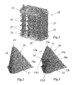
- FIG. 1 A current fuel injection system of a gas turbine with vortex generators (VGs) mounted on perpendicular flutes is shown in Fig. 1 .
- the fuel injection system 20 comprises a plurality of flutes 23 extending between a lower plate 21 and an upper plate 22. Each flute 23 has a leading edge 24 and a trailing edge 25 with respect to the gas flowing through the flute arrangement.
- the vortex generators (VGs) 27 are of a standard type (triangular prism with one trailing edge) designed to generate two strong vortices, which are expected to mix axially with the fuel injected by means of fuel injectors 28.
- Document US 8,677,756 B2 discloses a burner, such as for a secondary combustion chamber of a gas turbine with sequential combustion having first and second combustion chambers, including an injection device for introducing at least one gaseous fuel into the burner.
- the injection device has at least one body which is arranged in the burner with at least one nozzle for introducing the gaseous fuel into the burner.
- the body is configured as a streamlined body which has a streamlined cross-sectional profile and which extends with a longitudinal direction perpendicularly or at an inclination to a main flow direction prevailing in the burner.
- the at least one nozzle has its outlet orifice at or in a trailing edge of the streamlined body.
- the body has two lateral surfaces substantially parallel to the main flow direction.
- At least one vortex generator is located on at least one lateral surface upstream of the at least one nozzle.
- Document US 8,402,768 B2 relates to a burner for a combustion chamber of a gas turbine, with an injection device for the introduction of at least one gaseous and/or liquid fuel into the burner, wherein the injection device has at least one body which is arranged in the burner with at least one nozzle for introducing the at least one fuel into the burner, the at least one body being configured as a streamlined body which has a streamlined cross-sectional profile and which extends with a longitudinal direction perpendicularly or at an inclination to a main flow direction prevailing in the burner.
- the at least one nozzle has its outlet orifice at or in a trailing edge of the streamlined body, and with reference to a central plane of the streamlined body, the trailing edge is provided with at least two lobes extending in opposite transverse directions.
- Document US 2012/285173 A1 discloses a swirler including an annular housing with limiting walls. At least two vanes are arranged in the annular housing including the sidewalls of the swirler.
- the leading edge area of each vane has a profile, which is oriented parallel to a main flow direction prevailing at the leading edge position, wherein the profiles of the vanes turn from the main flow direction prevailing at the leading edge position to impose a swirl on the flow, and wherein, with reference to a central plane of the vanes the trailing edges are provided with at least two lobes in opposite transverse directions.
- a burner for a combustion chamber of a gas turbine including such a swirler and at least one nozzle having its outlet orifice at or in a trailing edge of the vane and to a method of operation of such a burner.
- Document US 2012/297787 A1 discloses a combined flow straightener and mixer as well as a burner for a combustion chamber of a gas turbine having such a mixing device.
- At least two streamlined bodies are arranged in a structure comprising the side walls of the mixer.
- the leading edge area of each streamlined body has a profile, which is oriented parallel to a main flow direction prevailing at the leading edge position, and with reference to a central plane of the streamlined bodies, the trailing edges are provided with at least two lobes in opposite transverse directions. The periodic deflections forming the lobes from two adjacent streamlined bodies are out of phase.
- the mixing and injection device includes a limiting wall that defines a gas-flow channel and at least two streamlined bodies, each extending in a first transverse direction into the gas-flow channel.
- Each streamlined body has two lateral surfaces that are arranged essentially parallel to the main-flow direction, the lateral surfaces being joined to one another at their upstream side to form a leading edge of the body and joined at their downstream side to form a trailing edge of the body.
- Each streamlined body has a cross-section perpendicular to the first transverse direction that is shaped as a streamlined profile.
- At least one of the streamlined bodies is provided with a mixing structure and with at least one fuel nozzle located at its trailing edge for introducing at least one fuel essentially parallel to the main-flow direction into the flow channel, wherein at least two of the streamlined bodies have different lengths along the first transverse direction such that they may be used for a can combustor.
- Document US 8,490,398 B2 relates to a burner for a single combustion chamber or first combustion chamber of a gas turbine, with an injection device for the introduction of at least one gaseous and/or liquid fuel into the burner, wherein the injection device has at least one body which is arranged in the burner with at least one nozzle for introducing the at least one fuel into the burner.
- the at least one body is located in a first section of the burner with a first cross-sectional area at a leading edge of the at least one body with reference to a main flow direction prevailing in the burner, wherein downstream of said body a mixing zone is located with a second cross-sectional area, and at and/or downstream of said body the cross-sectional area is reduced, such that the first cross-sectional area is larger than the second cross-sectional area.
- a vortex generator especially for a fuel injection system of a gas turbine, comprises a base area and a vortex generator body extending in a tapering fashion from said base area with a predetermined height.
- said vortex generator body forms at least two partial vortex generators, whereby each of said at least two partial vortex generators has its own trailing edge.
- said base area has the form of a triangle.
- said at least two partial vortex generators are arranged at different heights with respect to said base area.
- Said at least two partial vortex generators may be arranged one above the other with respect to said base area, said upper partial vortex generator having a first height and said lower partial vortex generator having a second height.
- said at least two partial vortex generators are arranged in a predetermined angle to each other.
- Said predetermined angle between said two partial vortex generators may vary between 0° and 45°.
- said at least two partial vortex generators each have an associated attack and sweep angle.
- Said at least two partial vortex generators may be arranged one above the other with respect to said base area, said upper partial vortex generator having a first height and said lower partial vortex generator having a second height, and said upper partial vortex generator may have a higher attack and sweep angle than said lower partial vortex generator.
- a fuel injection means is provided between said at least two partial vortex generators.
- Said fuel injection means may be located with different distances between said location and said at least two partial vortex generators.
- said at least two partial vortex generators have a leading edge, and the leading edge of said at least two partial vortex generators has a predetermined shape.
- the fuel injection system of a gas turbine according to the invention comprises at least one vortex generator, whereby said at least one vortex generator is a vortex generator according to the invention.
- Fig. 2 shows a standard vortex generator (VG) 16, as it is used in the fuel injection system 20 of Fig. 1 .
- This vortex generator 16 has a simple triangular base area 17 and a vortex generator body 16a in form of a simple triangular prism with a trailing edge 18 ending in an upper end 19.
- a vortex generator according to an embodiment of the invention is shown in comparison in Fig. 3 .
- the vortex generator 10 of Fig. 3 involves splitting the standard vortex generator 16 of Fig. 2 along a joining plane 15 into two partial vortex generators VG1 and VG2 rotated by a certain angle (see the two arrows in Fig. 3 ).
- the size of this "lobed" VG design is much larger than the standard designs thereby reducing the number of VGs mounted on the flutes.
- the number of fuel nozzles can be reduced in relation to the number of VGs.
- the upper partial vortex generator VG1 has a respective trailing edge 12a with a lower end 14 and an upper end 13a.
- the lower partial vortex generator VG2 has a respective trailing edge 12b starting at base area 11 and having an upper end 13b.
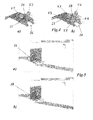
- Fig. 4 shows in comparison a conceptual description of a standard VG ( Fig. 4a ) and the new lobed VG design ( Fig. 4b ).
- the standard VG 16 has two strong vortices V1 and V2, which traverse axially and mix with the fuel injected by fuel injector 26 at an appropriate axial location ( Fig. 4a ).
- the lobed VG 10 produces four smaller vortices V3-V6, which are circumferentially traversing due to a vortex sheet VS emanating from the lobed flow ( Fig. 4b ).
- the lobed VG design there is a possibility to produce a higher number of large scale and small scale vortices.
- the lobed VG design can reduce significantly the number of mixing devices or vortex generators (VGs) required in a fuel injector.
- Fig. 5 shows in comparison (in a plane perpendicular to the flow direction) the flow structures from the standard ( Fig. 5a ) and lobed VG design ( Fig. 5b ) at the exit of the respective VG.
- the streamline plots show that the lobed VG design produces four distinct vortices. The size of the vortices needs to be controlled by optimizing the design features of the lobed-VG concept.
- Fig. 6 shows in comparison the velocity distribution for the standard VG ( Fig. 6a ) and lobed VG designs ( Fig. 6b ) in form of the axial velocity vectors near the VG trailing edge.
- the lobed VG's ( Fig. 6b ) with their leading edge 29 and their trailing edges 12a and 12b (see also Fig. 7b ) produce multiple small scale vortices when compared to the two simple vortex structures produced by the standard VGs ( Fig. 6a ).
- the locations of vortices are in addition circumferentially spread for the lobed VG configuration. The circumferential spread of the vortices helps in reaching the fuel much faster.
- Fig. 7 shows in comparison the flow structures and fuel distribution for the standard VG ( Fig. 7a ) and lobed VG design ( Fig. 7b ).
- the lobed VG design ( Fig. 7b ) produces a flow field spread circumferentially resulting in improved mixing of the fuel with hot gases.
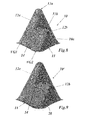
- Fig. 8 shows the angle between the two (partial) VGs VG1 and VG2 of the lobed VG design, which can be allowed to vary between 0 to 45 degrees.
- the height h1 and h2 of the (two) VG trailing edges 12a and 12b can be varied so as to control hot gas mass flow. This also ensures the vortex breakdown characteristics of the lobed flow.
- Fig. 9 shows another embodiment of the VG according to the invention, wherein fuel can be injected by means of a fuel injector 28 between the (partial) VGs.
- a novel lobed vortex generator based fuel injection system is proposed to introduce rapid mixing at allowable pressure drops for higher firing temperature gas turbines.
- This invention targets towards accomplishing fuel-air mixing within short burner-mixing length or time scales.
- the concept includes aerodynamically facilitated axial fuel injection with mixing promoted by multiple vortices and lobed flow structures produced by a new lobed-VG design.
- the burner is designed to operate at increased hot gas temperature (2000K or more) or fuel flexibility without suffering on high NOx emissions or flashback.
- the proposed lobed-VG concept when compared to previous concepts is simpler, lower cost with less number of complex VG structures. The fuel distribution is much better for lobed-VG design due to reduced number of nozzles.
Abstract
Description
- The present invention relates to vortex generators. It refers to a vortex generator according to the preamble of claim 1.
- The present invention further refers to a fuel injection system of a gas turbine with a vortex generator.
- A current fuel injection system of a gas turbine with vortex generators (VGs) mounted on perpendicular flutes is shown in
Fig. 1 . Thefuel injection system 20 comprises a plurality offlutes 23 extending between alower plate 21 and anupper plate 22. Eachflute 23 has a leadingedge 24 and atrailing edge 25 with respect to the gas flowing through the flute arrangement. The vortex generators (VGs) 27 are of a standard type (triangular prism with one trailing edge) designed to generate two strong vortices, which are expected to mix axially with the fuel injected by means offuel injectors 28. - The mixing of fuel with vortices is often delayed due to slow interaction of vortices with the fuel jets. There are multiple numbers of
vortex generators 27 placed on theflutes 23 posing difficulties in cooling and manufacturing. Furthermore, the current design poses challenges in terms of uniform fuel distribution for the nozzles. - Various other vortex generators and arrangements have been proposed in the past.
- Document
US 8,677,756 B2 discloses a burner, such as for a secondary combustion chamber of a gas turbine with sequential combustion having first and second combustion chambers, including an injection device for introducing at least one gaseous fuel into the burner. The injection device has at least one body which is arranged in the burner with at least one nozzle for introducing the gaseous fuel into the burner. The body is configured as a streamlined body which has a streamlined cross-sectional profile and which extends with a longitudinal direction perpendicularly or at an inclination to a main flow direction prevailing in the burner. The at least one nozzle has its outlet orifice at or in a trailing edge of the streamlined body. The body has two lateral surfaces substantially parallel to the main flow direction. At least one vortex generator is located on at least one lateral surface upstream of the at least one nozzle. - Document
US 8,402,768 B2 relates to a burner for a combustion chamber of a gas turbine, with an injection device for the introduction of at least one gaseous and/or liquid fuel into the burner, wherein the injection device has at least one body which is arranged in the burner with at least one nozzle for introducing the at least one fuel into the burner, the at least one body being configured as a streamlined body which has a streamlined cross-sectional profile and which extends with a longitudinal direction perpendicularly or at an inclination to a main flow direction prevailing in the burner. The at least one nozzle has its outlet orifice at or in a trailing edge of the streamlined body, and with reference to a central plane of the streamlined body, the trailing edge is provided with at least two lobes extending in opposite transverse directions. - Document
US 2012/285173 A1 discloses a swirler including an annular housing with limiting walls. At least two vanes are arranged in the annular housing including the sidewalls of the swirler. The leading edge area of each vane has a profile, which is oriented parallel to a main flow direction prevailing at the leading edge position, wherein the profiles of the vanes turn from the main flow direction prevailing at the leading edge position to impose a swirl on the flow, and wherein, with reference to a central plane of the vanes the trailing edges are provided with at least two lobes in opposite transverse directions. A burner for a combustion chamber of a gas turbine including such a swirler and at least one nozzle having its outlet orifice at or in a trailing edge of the vane and to a method of operation of such a burner. - Document
US 2012/297787 A1 discloses a combined flow straightener and mixer as well as a burner for a combustion chamber of a gas turbine having such a mixing device. At least two streamlined bodies are arranged in a structure comprising the side walls of the mixer. The leading edge area of each streamlined body has a profile, which is oriented parallel to a main flow direction prevailing at the leading edge position, and with reference to a central plane of the streamlined bodies, the trailing edges are provided with at least two lobes in opposite transverse directions. The periodic deflections forming the lobes from two adjacent streamlined bodies are out of phase. - Document
US 2014/109588 A1 relates to a burner for a combustion chamber of a gas turbine with a mixing and injection device. The mixing and injection device includes a limiting wall that defines a gas-flow channel and at least two streamlined bodies, each extending in a first transverse direction into the gas-flow channel. Each streamlined body has two lateral surfaces that are arranged essentially parallel to the main-flow direction, the lateral surfaces being joined to one another at their upstream side to form a leading edge of the body and joined at their downstream side to form a trailing edge of the body. Each streamlined body has a cross-section perpendicular to the first transverse direction that is shaped as a streamlined profile. At least one of the streamlined bodies is provided with a mixing structure and with at least one fuel nozzle located at its trailing edge for introducing at least one fuel essentially parallel to the main-flow direction into the flow channel, wherein at least two of the streamlined bodies have different lengths along the first transverse direction such that they may be used for a can combustor. - Document
US 8,490,398 B2 relates to a burner for a single combustion chamber or first combustion chamber of a gas turbine, with an injection device for the introduction of at least one gaseous and/or liquid fuel into the burner, wherein the injection device has at least one body which is arranged in the burner with at least one nozzle for introducing the at least one fuel into the burner. The at least one body is located in a first section of the burner with a first cross-sectional area at a leading edge of the at least one body with reference to a main flow direction prevailing in the burner, wherein downstream of said body a mixing zone is located with a second cross-sectional area, and at and/or downstream of said body the cross-sectional area is reduced, such that the first cross-sectional area is larger than the second cross-sectional area. - It is an object of the present invention to provide an improved vortex generator and a fuel injection system equipped with such vortex generators, which effect rapid mixing at allowable pressure drops for higher firing temperature gas turbines.
- It is another object of the invention to fuel-air mixing within short burner-mixing length or time scales.
- These and other objects are obtained by a vortex generator according to Claim 1.
- According to the invention, a vortex generator, especially for a fuel injection system of a gas turbine, comprises a base area and a vortex generator body extending in a tapering fashion from said base area with a predetermined height.
- It is characterized in that said vortex generator body forms at least two partial vortex generators, whereby each of said at least two partial vortex generators has its own trailing edge.
- According to an embodiment of the invention said base area has the form of a triangle.
- According to another embodiment of the invention said at least two partial vortex generators are arranged at different heights with respect to said base area.
- Said at least two partial vortex generators may be arranged one above the other with respect to said base area, said upper partial vortex generator having a first height and said lower partial vortex generator having a second height.
- According to another embodiment of the invention said at least two partial vortex generators are arranged in a predetermined angle to each other.
- Said predetermined angle between said two partial vortex generators may vary between 0° and 45°.
- According to another embodiment of the invention said at least two partial vortex generators each have an associated attack and sweep angle.
- Said at least two partial vortex generators may be arranged one above the other with respect to said base area, said upper partial vortex generator having a first height and said lower partial vortex generator having a second height, and said upper partial vortex generator may have a higher attack and sweep angle than said lower partial vortex generator.
- According to another embodiment of the invention a fuel injection means is provided between said at least two partial vortex generators.
- Said fuel injection means may be located with different distances between said location and said at least two partial vortex generators.
- According to another embodiment of the invention said at least two partial vortex generators have a leading edge, and the leading edge of said at least two partial vortex generators has a predetermined shape.
- The fuel injection system of a gas turbine according to the invention comprises at least one vortex generator, whereby said at least one vortex generator is a vortex generator according to the invention.
- The present invention is now to be explained more closely by means of different embodiments and with reference to the attached drawings.
- Fig. 1
- shows a current fuel injection system with current vortex generators (VGs) mounted on vertical flutes;
- Fig. 2
- shows a standard vortex generator (VG);
- Fig. 3
- shows a so-called lobed vortex generator (VG) according to an embodiment of the invention;
- Fig. 4
- shows in comparison a conceptual description of a standard VG (
Fig. 4a ) and the new lobed VG design (Fig. 4b ); - Fig. 5
- shows in comparison the flow structures and fuel distribution for the standard VG (
Fig. 5a ) and lobed VG design (Fig. 5b ); - Fig. 6
- shows in comparison the velocity distribution for the standard VG (
Fig. 6a ) and lobed VG designs (Fig. 6b ); - Fig. 7
- shows in comparison the flow structures and fuel distribution for the standard VG (
Fig. 7a ) and lobed VG design (Fig. 7b ); - Fig. 8
- shows the angle between the two (partial) VGs of the lobed VG design, which can be allowed to vary between 0 to 45 degrees, and the height of the (two) VG trailing edges, which can be varied so as to control hot gas mass flows; and
- Fig. 9
- shows another embodiment of the VG according to the invention, wherein fuel can be injected between the (partial) VGs.
-
Fig. 2 shows a standard vortex generator (VG) 16, as it is used in thefuel injection system 20 ofFig. 1 . Thisvortex generator 16 has a simpletriangular base area 17 and avortex generator body 16a in form of a simple triangular prism with a trailingedge 18 ending in anupper end 19. - A vortex generator according to an embodiment of the invention is shown in comparison in
Fig. 3 . Thevortex generator 10 ofFig. 3 involves splitting thestandard vortex generator 16 ofFig. 2 along a joiningplane 15 into two partial vortex generators VG1 and VG2 rotated by a certain angle (see the two arrows inFig. 3 ). The size of this "lobed" VG design is much larger than the standard designs thereby reducing the number of VGs mounted on the flutes. In addition the number of fuel nozzles can be reduced in relation to the number of VGs. The upper partial vortex generator VG1 has arespective trailing edge 12a with alower end 14 and anupper end 13a. The lower partial vortex generator VG2 has arespective trailing edge 12b starting atbase area 11 and having anupper end 13b. -
Fig. 4 shows in comparison a conceptual description of a standard VG (Fig. 4a ) and the new lobed VG design (Fig. 4b ). Thestandard VG 16 has two strong vortices V1 and V2, which traverse axially and mix with the fuel injected byfuel injector 26 at an appropriate axial location (Fig. 4a ). Thelobed VG 10 produces four smaller vortices V3-V6, which are circumferentially traversing due to a vortex sheet VS emanating from the lobed flow (Fig. 4b ). With the lobed VG design there is a possibility to produce a higher number of large scale and small scale vortices. In addition the lobed VG design can reduce significantly the number of mixing devices or vortex generators (VGs) required in a fuel injector. -
Fig. 5 shows in comparison (in a plane perpendicular to the flow direction) the flow structures from the standard (Fig. 5a ) and lobed VG design (Fig. 5b ) at the exit of the respective VG. The streamline plots show that the lobed VG design produces four distinct vortices. The size of the vortices needs to be controlled by optimizing the design features of the lobed-VG concept. -
Fig. 6 shows in comparison the velocity distribution for the standard VG (Fig. 6a ) and lobed VG designs (Fig. 6b ) in form of the axial velocity vectors near the VG trailing edge. The lobed VG's (Fig. 6b ) with their leadingedge 29 and theirtrailing edges Fig. 7b ) produce multiple small scale vortices when compared to the two simple vortex structures produced by the standard VGs (Fig. 6a ). The locations of vortices are in addition circumferentially spread for the lobed VG configuration. The circumferential spread of the vortices helps in reaching the fuel much faster. -
Fig. 7 shows in comparison the flow structures and fuel distribution for the standard VG (Fig. 7a ) and lobed VG design (Fig. 7b ). The lobed VG design (Fig. 7b ) produces a flow field spread circumferentially resulting in improved mixing of the fuel with hot gases. -
Fig. 8 shows the angle between the two (partial) VGs VG1 and VG2 of the lobed VG design, which can be allowed to vary between 0 to 45 degrees. The height h1 and h2 of the (two)VG trailing edges - Finally,
Fig. 9 shows another embodiment of the VG according to the invention, wherein fuel can be injected by means of afuel injector 28 between the (partial) VGs. - In summary, a novel lobed vortex generator based fuel injection system is proposed to introduce rapid mixing at allowable pressure drops for higher firing temperature gas turbines. This invention targets towards accomplishing fuel-air mixing within short burner-mixing length or time scales. The concept includes aerodynamically facilitated axial fuel injection with mixing promoted by multiple vortices and lobed flow structures produced by a new lobed-VG design. As a result, the burner is designed to operate at increased hot gas temperature (2000K or more) or fuel flexibility without suffering on high NOx emissions or flashback. The proposed lobed-VG concept when compared to previous concepts is simpler, lower cost with less number of complex VG structures. The fuel distribution is much better for lobed-VG design due to reduced number of nozzles.
- The advantages of the new design are:
- Doubled number of vortex structures for the lobed design when compared to standard VG design which has only two vortex structures.
- Circumferential spread of flow structures due to lobed flow resulting in rapid mixing with fuel.
- The number of mixing devices can be reduced with the lobed-VG design. This helps in decreased cooling requirement for the flutes. The lobed-VG design will require smaller number of VGs mounted on the flutes compared to the standard VGs. For example, in the GT36-S6 gas turbine, there are 32 VGs and 36 fuel nozzles used. With the lobed-VG design one can reduce the number of VGs and fuel nozzles to at least 50%.
- The size of the lobed VGs will be much larger than the mini-VGs and also with less fuel nozzles, thus the fuel distribution is improved.
- The production of multiple large scale and small scale mixing structures from the lobed-VG design can simplify the design.
- The cost of the lobed-VG should be lower than the mini-VGs or lobes design because of a less VGs and injectors.
- Design simplicity: The lobed-VG design will eliminate the need for lobed fuel injectors. The design is simple because one gets vortices and lobed flow by just orienting two (partial) VGs at an angle.
- Less parts: Less number of mixing devices and nozzles with the lobed-VG design when compared to the standard mini-VG or lobed designs.
- Easy to manufacture by Selective Laser Melting (SLM): The lobed VGs have larger sized VGs and the lobe structures are produced by arranging the VGs at an angle. There is no special manufacturing requirement for the lobes.
- The new vortex generator design may have different embodiments:
- 1) The angle between the two partial VGs can be allowed to vary between 0° and 45°.
- 2) The height of the partial VG trailing edges can be varied so as to control hot gas mass flows. This also ensures the vortex breakdown characteristics of the lobed flow.
- 3) Fuel can be injected between the partial VGs. With this option, one can eliminate the need for central fuel nozzles.
- 4) The distance between the fuel nozzle injection location and the partial VGs can be altered.
- 5) The attack and sweep angles of the VG's can be modified to reduce flow separation. The upper VG can be provided with high attack and sweep angle and the lower VG can be with lower attack and sweep angle.
- 6) The shape of the leading
edge 29 of the VG's can be modified (straight, elliptical, circular etc.) to alter vortex characteristics. -
- 10
- vortex generator
- 10a,16a
- vortex generator body
- 11,17
- base area (triangular)
- 12a,b
- trailing edge
- 13a,b
- upper end (trailing edge)
- 14
- lower end (trailing edge)
- 15
- joining plane
- 16
- vortex generator (prior art)
- 18
- trailing edge
- 19
- upper end (trailing edge)
- 20
- fuel injection system (gas turbine)
- 21
- lower plate
- 22
- upper plate
- 23
- flute
- 24
- leading edge
- 25
- trailing edge
- 26
- fuel injector (nozzle)
- 27
- vortex generator
- 28
- fuel injector (nozzle)
- 29
- leading edge
- V1-V6
- vortex
- VG1,VG2
- vortex generator (partial)
- VS
- vortex sheet
Claims (12)
- Vortex generator (10), especially for a fuel injection system of a gas turbine, said vortex generator (10) comprising a base area (11) and a vortex generator body (10a) extending in a tapering fashion from said base area (11) with a predetermined height (h1+h2), characterized in that said vortex generator body (10a) forms at least two partial vortex generators (VG1, VG2), whereby each of said at least two partial vortex generators (VG1, VG2) has its own trailing edge (12a, 12b).
- Vortex generator as claimed in Claim 1, characterized in that said base area (11) has the form of a triangle.
- Vortex generator as claimed in Claim 1, characterized in that said at least two partial vortex generators (VG1, VG2) are arranged at different heights with respect to said base area (11).
- Vortex generator as claimed in Claim 3, characterized in that said at least two partial vortex generators (VG1, VG2) are arranged one above the other with respect to said base area (11), said upper partial vortex generator (VG1) having a first height (h1) and said lower partial vortex generator (VG2) having a second height (h2).
- Vortex generator as claimed in Claim 1, characterized in that said at least two partial vortex generators (VG1, VG2) are arranged in a predetermined angle to each other.
- Vortex generator as claimed in Claim 5, characterized in that said predetermined angle between said two partial vortex generators (VG1, VG2) can vary between 0° and 45°.
- Vortex generator as claimed in Claim 1, characterized in that said at least two partial vortex generators (VG1, VG2) each have an associated attack and sweep angle.
- Vortex generator as claimed in Claim 7, characterized in that said at least two partial vortex generators (VG1, VG2) are arranged one above the other with respect to said base area (11), said upper partial vortex generator (VG1) having a first height (h1) and said lower partial vortex generator (VG2) having a second height (h2), and that said upper partial vortex generator (VG1) has a higher attack and sweep angle than said lower partial vortex generator (VG2).
- Vortex generator as claimed in Claim 1, characterized in that a fuel injection means (26) is provided between said at least two partial vortex generators (VG1, VG2).
- Vortex generator as claimed in Claim 9, characterized in that said fuel injection means (26) is located with different distances between said location and said at least two partial vortex generators (VG1, VG2).
- Vortex generator as claimed in Claim 1, characterized in that said at least two partial vortex generators (VG1, VG2) have a leading edge (29), and that the leading edge (29) of said at least two partial vortex generators (VG1, VG2) has a predetermined shape.
- Fuel injection system of a gas turbine, comprising at least one vortex generator, characterized in that said at least one vortex generator is a vortex generator (10) according to one of the Claims 1 to 11.
Priority Applications (3)
| Application Number | Priority Date | Filing Date | Title |
|---|---|---|---|
| EP15187052.4A EP3147569A1 (en) | 2015-09-28 | 2015-09-28 | Vortex generator, and fuel injection system of a gas turbine with such vortex generator |
| CN201610857906.4A CN106958835A (en) | 2015-09-28 | 2016-09-28 | The fuel injection system of vortex generator and combustion gas turbine with vortex generator |
| US15/278,773 US20170089584A1 (en) | 2015-09-28 | 2016-09-28 | Vortex generator, and fuel injection system of a gas turbine with such vortex generator |
Applications Claiming Priority (1)
| Application Number | Priority Date | Filing Date | Title |
|---|---|---|---|
| EP15187052.4A EP3147569A1 (en) | 2015-09-28 | 2015-09-28 | Vortex generator, and fuel injection system of a gas turbine with such vortex generator |
Publications (1)
| Publication Number | Publication Date |
|---|---|
| EP3147569A1 true EP3147569A1 (en) | 2017-03-29 |
Family
ID=54249327
Family Applications (1)
| Application Number | Title | Priority Date | Filing Date |
|---|---|---|---|
| EP15187052.4A Withdrawn EP3147569A1 (en) | 2015-09-28 | 2015-09-28 | Vortex generator, and fuel injection system of a gas turbine with such vortex generator |
Country Status (3)
| Country | Link |
|---|---|
| US (1) | US20170089584A1 (en) |
| EP (1) | EP3147569A1 (en) |
| CN (1) | CN106958835A (en) |
Families Citing this family (4)
| Publication number | Priority date | Publication date | Assignee | Title |
|---|---|---|---|---|
| US10151325B2 (en) * | 2015-04-08 | 2018-12-11 | General Electric Company | Gas turbine diffuser strut including a trailing edge flap and methods of assembling the same |
| EP3115693B1 (en) * | 2015-07-10 | 2021-09-01 | Ansaldo Energia Switzerland AG | Sequential combustor and method for operating the same |
| US11242806B2 (en) * | 2017-11-20 | 2022-02-08 | Power Systems Mfg., Llc | Method of controlling fuel injection in a reheat combustor for a combustor unit of a gas turbine |
| EP4078032A1 (en) * | 2020-03-31 | 2022-10-26 | Siemens Energy Global GmbH & Co. KG | Burner component of a burner, and burner of a gas turbine having a burner component of this type |
Citations (10)
| Publication number | Priority date | Publication date | Assignee | Title |
|---|---|---|---|---|
| US5058837A (en) * | 1989-04-07 | 1991-10-22 | Wheeler Gary O | Low drag vortex generators |
| US6263660B1 (en) * | 1998-08-17 | 2001-07-24 | Ramgen Power Systems, Inc. | Apparatus and method for fuel-air mixing before supply of low pressure lean pre-mix to combustor for rotating ramjet engine driving a shaft |
| US20120285173A1 (en) | 2011-05-11 | 2012-11-15 | Alstom Technology Ltd | Lobed swirler |
| US20120297787A1 (en) | 2011-05-11 | 2012-11-29 | Alstom Technology Ltd | Flow straightener and mixer |
| US8402768B2 (en) | 2009-11-07 | 2013-03-26 | Alstom Technology Ltd. | Reheat burner injection system |
| US8490398B2 (en) | 2009-11-07 | 2013-07-23 | Alstom Technology Ltd. | Premixed burner for a gas turbine combustor |
| US8677756B2 (en) | 2009-11-07 | 2014-03-25 | Alstom Technology Ltd. | Reheat burner injection system |
| US20140109588A1 (en) | 2012-10-23 | 2014-04-24 | Alstom Technology Ltd | Burner for a can combustor |
| US20140328692A1 (en) * | 2013-05-02 | 2014-11-06 | General Electric Company | Attachment system and method for wind turbine vortex generators |
| US20150010407A1 (en) * | 2013-07-08 | 2015-01-08 | Alonso O. Zamora Rodriguez | Reduced noise vortex generator for wind turbine blade |
-
2015
- 2015-09-28 EP EP15187052.4A patent/EP3147569A1/en not_active Withdrawn
-
2016
- 2016-09-28 CN CN201610857906.4A patent/CN106958835A/en active Pending
- 2016-09-28 US US15/278,773 patent/US20170089584A1/en not_active Abandoned
Patent Citations (10)
| Publication number | Priority date | Publication date | Assignee | Title |
|---|---|---|---|---|
| US5058837A (en) * | 1989-04-07 | 1991-10-22 | Wheeler Gary O | Low drag vortex generators |
| US6263660B1 (en) * | 1998-08-17 | 2001-07-24 | Ramgen Power Systems, Inc. | Apparatus and method for fuel-air mixing before supply of low pressure lean pre-mix to combustor for rotating ramjet engine driving a shaft |
| US8402768B2 (en) | 2009-11-07 | 2013-03-26 | Alstom Technology Ltd. | Reheat burner injection system |
| US8490398B2 (en) | 2009-11-07 | 2013-07-23 | Alstom Technology Ltd. | Premixed burner for a gas turbine combustor |
| US8677756B2 (en) | 2009-11-07 | 2014-03-25 | Alstom Technology Ltd. | Reheat burner injection system |
| US20120285173A1 (en) | 2011-05-11 | 2012-11-15 | Alstom Technology Ltd | Lobed swirler |
| US20120297787A1 (en) | 2011-05-11 | 2012-11-29 | Alstom Technology Ltd | Flow straightener and mixer |
| US20140109588A1 (en) | 2012-10-23 | 2014-04-24 | Alstom Technology Ltd | Burner for a can combustor |
| US20140328692A1 (en) * | 2013-05-02 | 2014-11-06 | General Electric Company | Attachment system and method for wind turbine vortex generators |
| US20150010407A1 (en) * | 2013-07-08 | 2015-01-08 | Alonso O. Zamora Rodriguez | Reduced noise vortex generator for wind turbine blade |
Also Published As
| Publication number | Publication date |
|---|---|
| US20170089584A1 (en) | 2017-03-30 |
| CN106958835A (en) | 2017-07-18 |
Similar Documents
| Publication | Publication Date | Title |
|---|---|---|
| EP2778529B1 (en) | Combustor for gas turbine engine | |
| EP3182013B1 (en) | Burner for a sequential combustion chamber | |
| US20140090390A1 (en) | Flamesheet combustor dome | |
| US20170089584A1 (en) | Vortex generator, and fuel injection system of a gas turbine with such vortex generator | |
| US20130232979A1 (en) | System for enhancing mixing in a multi-tube fuel nozzle | |
| US20140238036A1 (en) | Fuel/air mixing system for fuel nozzle | |
| US10920986B2 (en) | Gas turbine combustor base plate configuration | |
| US9127843B2 (en) | Combustor for gas turbine engine | |
| US9651260B2 (en) | Annular combustion chamber for a turbine engine | |
| EP2778533B1 (en) | Combustor for gas turbine engine | |
| EP2618057B1 (en) | Turbine system | |
| US9810432B2 (en) | Method for premixing air with a gaseous fuel and burner arrangement for conducting said method | |
| US20160061452A1 (en) | Corrugated cyclone mixer assembly to facilitate reduced nox emissions and improve operability in a combustor system | |
| EP2778370B1 (en) | Combustor for gas turbine engine | |
| US20150040576A1 (en) | Counter swirl doublet combustor | |
| EP2644997A1 (en) | Mixing arrangement for mixing fuel with a stream of oxygen containing gas | |
| EP2211109A1 (en) | Burner of a gas turbine and method for mixing a fuel with a gaseous flow | |
| EP2722591A1 (en) | Multiple cone gas turbine burner | |
| EP3472518B1 (en) | Fuel oil axial stage combustion for improved turbine combustor performance | |
| US9441837B2 (en) | Premix burner of the multi-cone type for a gas turbine | |
| EP3026344B1 (en) | Burner of a gas turbine | |
| EP2933559A1 (en) | Fuel mixing arragement and combustor with such a fuel mixing arrangement | |
| EP2796788A1 (en) | Swirl generator | |
| CN101907304A (en) | Concave surface type splash plate fuel-injection atomization device | |
| EP4276358A1 (en) | Fuel nozzle with multiple air passages |
Legal Events
| Date | Code | Title | Description |
|---|---|---|---|
| PUAI | Public reference made under article 153(3) epc to a published international application that has entered the european phase |
Free format text: ORIGINAL CODE: 0009012 |
|
| AK | Designated contracting states |
Kind code of ref document: A1 Designated state(s): AL AT BE BG CH CY CZ DE DK EE ES FI FR GB GR HR HU IE IS IT LI LT LU LV MC MK MT NL NO PL PT RO RS SE SI SK SM TR |
|
| AX | Request for extension of the european patent |
Extension state: BA ME |
|
| RAP1 | Party data changed (applicant data changed or rights of an application transferred) |
Owner name: ANSALDO ENERGIA SWITZERLAND AG |
|
| 17P | Request for examination filed |
Effective date: 20170927 |
|
| RBV | Designated contracting states (corrected) |
Designated state(s): AL AT BE BG CH CY CZ DE DK EE ES FI FR GB GR HR HU IE IS IT LI LT LU LV MC MK MT NL NO PL PT RO RS SE SI SK SM TR |
|
| STAA | Information on the status of an ep patent application or granted ep patent |
Free format text: STATUS: THE APPLICATION IS DEEMED TO BE WITHDRAWN |
|
| 18D | Application deemed to be withdrawn |
Effective date: 20190402 |