EP3147499A1 - Rotor blade comprising a sound optimized profile and method for manufacturing a rotor blade - Google Patents
Rotor blade comprising a sound optimized profile and method for manufacturing a rotor blade Download PDFInfo
- Publication number
- EP3147499A1 EP3147499A1 EP16187323.7A EP16187323A EP3147499A1 EP 3147499 A1 EP3147499 A1 EP 3147499A1 EP 16187323 A EP16187323 A EP 16187323A EP 3147499 A1 EP3147499 A1 EP 3147499A1
- Authority
- EP
- European Patent Office
- Prior art keywords
- rotor blade
- profile
- trailing edge
- optimized
- rotor
- Prior art date
- Legal status (The legal status is an assumption and is not a legal conclusion. Google has not performed a legal analysis and makes no representation as to the accuracy of the status listed.)
- Granted
Links
- 238000004519 manufacturing process Methods 0.000 title claims abstract description 10
- 238000000034 method Methods 0.000 title claims description 11
- 238000006073 displacement reaction Methods 0.000 claims abstract description 6
- 230000009467 reduction Effects 0.000 claims abstract description 4
- 230000003628 erosive effect Effects 0.000 claims description 10
- 230000008859 change Effects 0.000 description 5
- 238000004088 simulation Methods 0.000 description 3
- 230000010354 integration Effects 0.000 description 2
- 230000007704 transition Effects 0.000 description 2
- 230000006872 improvement Effects 0.000 description 1
Images


Classifications
-
- F—MECHANICAL ENGINEERING; LIGHTING; HEATING; WEAPONS; BLASTING
- F03—MACHINES OR ENGINES FOR LIQUIDS; WIND, SPRING, OR WEIGHT MOTORS; PRODUCING MECHANICAL POWER OR A REACTIVE PROPULSIVE THRUST, NOT OTHERWISE PROVIDED FOR
- F03D—WIND MOTORS
- F03D1/00—Wind motors with rotation axis substantially parallel to the air flow entering the rotor
- F03D1/06—Rotors
- F03D1/0608—Rotors characterised by their aerodynamic shape
- F03D1/0633—Rotors characterised by their aerodynamic shape of the blades
-
- F—MECHANICAL ENGINEERING; LIGHTING; HEATING; WEAPONS; BLASTING
- F05—INDEXING SCHEMES RELATING TO ENGINES OR PUMPS IN VARIOUS SUBCLASSES OF CLASSES F01-F04
- F05B—INDEXING SCHEME RELATING TO WIND, SPRING, WEIGHT, INERTIA OR LIKE MOTORS, TO MACHINES OR ENGINES FOR LIQUIDS COVERED BY SUBCLASSES F03B, F03D AND F03G
- F05B2240/00—Components
- F05B2240/20—Rotors
- F05B2240/30—Characteristics of rotor blades, i.e. of any element transforming dynamic fluid energy to or from rotational energy and being attached to a rotor
-
- F—MECHANICAL ENGINEERING; LIGHTING; HEATING; WEAPONS; BLASTING
- F05—INDEXING SCHEMES RELATING TO ENGINES OR PUMPS IN VARIOUS SUBCLASSES OF CLASSES F01-F04
- F05B—INDEXING SCHEME RELATING TO WIND, SPRING, WEIGHT, INERTIA OR LIKE MOTORS, TO MACHINES OR ENGINES FOR LIQUIDS COVERED BY SUBCLASSES F03B, F03D AND F03G
- F05B2260/00—Function
- F05B2260/96—Preventing, counteracting or reducing vibration or noise
-
- Y—GENERAL TAGGING OF NEW TECHNOLOGICAL DEVELOPMENTS; GENERAL TAGGING OF CROSS-SECTIONAL TECHNOLOGIES SPANNING OVER SEVERAL SECTIONS OF THE IPC; TECHNICAL SUBJECTS COVERED BY FORMER USPC CROSS-REFERENCE ART COLLECTIONS [XRACs] AND DIGESTS
- Y02—TECHNOLOGIES OR APPLICATIONS FOR MITIGATION OR ADAPTATION AGAINST CLIMATE CHANGE
- Y02E—REDUCTION OF GREENHOUSE GAS [GHG] EMISSIONS, RELATED TO ENERGY GENERATION, TRANSMISSION OR DISTRIBUTION
- Y02E10/00—Energy generation through renewable energy sources
- Y02E10/70—Wind energy
- Y02E10/72—Wind turbines with rotation axis in wind direction
-
- Y—GENERAL TAGGING OF NEW TECHNOLOGICAL DEVELOPMENTS; GENERAL TAGGING OF CROSS-SECTIONAL TECHNOLOGIES SPANNING OVER SEVERAL SECTIONS OF THE IPC; TECHNICAL SUBJECTS COVERED BY FORMER USPC CROSS-REFERENCE ART COLLECTIONS [XRACs] AND DIGESTS
- Y02—TECHNOLOGIES OR APPLICATIONS FOR MITIGATION OR ADAPTATION AGAINST CLIMATE CHANGE
- Y02P—CLIMATE CHANGE MITIGATION TECHNOLOGIES IN THE PRODUCTION OR PROCESSING OF GOODS
- Y02P70/00—Climate change mitigation technologies in the production process for final industrial or consumer products
- Y02P70/50—Manufacturing or production processes characterised by the final manufactured product
Definitions
- the invention relates to a rotor blade of a wind energy plant, wherein the rotor blade has a suction side, a pressure side, a rotor blade nose and a rotor blade trailing edge, which extend between a rotor blade root and a rotor blade tip and define a profile of the rotor blade.
- the invention relates to a wind turbine with a rotor blade and a method for producing a rotor blade of a wind turbine, wherein the rotor blade has a suction side, a pressure side, a rotor blade nose and a rotor blade trailing edge, which extend between a rotor blade root and a rotor blade tip and define a profile of the rotor blade ,
- the rotor blades of a wind turbine always comprise a suction side and a pressure side, which often extend on the outside of a suction side shell and a pressure side shell.
- a suction side shell and a pressure side shell In the area of a rotor blade nose and a rotor blade trailing edge, the suction side shell and the pressure side shell are joined together, for example glued.
- the result is a rotor blade, which extends from a rotor blade root, where it is connected to the hub of a wind turbine, to the rotor blade tip.
- the shapes of the suction side, pressure side and the rotor blade nose and rotor blade trailing edge define the profile of the rotor blade.
- the yield of a wind turbine is essentially determined by the profile of its rotor blades. For this reason, rotor blades are optimized in terms of their profile for optimum performance. Inevitably, however, flow noise occurs on the rotor blades during operation of a wind power plant. For noise protection reasons, therefore, minimum distances, for example to residential areas or other protection areas, must be observed. This limits the possible locations where the wind turbine in question can be used.
- serrations are provided in an outer portion of the rotor blade at the trailing edge thereof.
- a corresponding rotor blade is for example made US 2011/0142666 A1 known.
- the measures mentioned for changing the aerodynamic profile of the rotor blade in the rotor blade end region reduce the sound power level of the wind energy plant.
- lower maximum rotor sound power levels can be guaranteed without having to reduce the sound power level by lowering the blade tip speed.
- the latter measure is always associated with performance losses and is taken in so-called. Sound-reduced operations.
- lower maximum Rotor sound power level can be guaranteed, so that it can also be used in locations where conventional systems can not be installed due to their high noise emissions or at least temporarily operated in low-noise modes. Since it is advantageously dispensed with reduced-noise modes, also increases the yield of the wind turbine.
- the performance-optimized profile of the rotor blade is determined, for example, by numerical simulation or by practical tests, for example in the wind tunnel.
- one or more of the aforementioned measures are taken in accordance with aspects of the invention. It has proven to be advantageous to make a transition to a sound-optimized blade tip profile in the outer region of the rotor blade, namely in the rotor blade end region, which delivers low sound power level even without trailing edge spikes.
- the sound-optimized profile is optimized and designed especially for turbulent flow around. It is a goal to minimize the displacement thickness at the trailing edge. This is achieved by the aforementioned measures, starting from the performance-optimized profile.
- the rotor blade end region starts at 80%, 85%, or 90% of the relative blade length.
- the relative blade length is understood to mean the quotient of the relative position in the longitudinal direction of the rotor blade divided by the rotor radius.
- the rotor blade end region extends approximately 3 m to 4 m in the direction of the rotor blade root. In other words, therefore, the rotor blade in its outermost 3 m to 4 m on a sound-optimized and no performance-optimized profile.
- the rotor blade is formed by having trailing edge serrations on the rotor blade trailing edge in a middle section, no trailing edge serrations being present in the rotor blade end region, and the middle section starting from the rotor blade end region in the direction of the rotor blade end Rotor blade root extends.
- Trailing serrations are known per se as means for reducing the flow noise of rotor blades.
- the transport of the rotor blade is considerably simpler. If trailing edge points are also present at the outer end of the rotor blade, there is always the danger during transport that the trailing edge points are damaged.
- a conventional transport of the rotor blade is possible, as is known from rotor blades which have no trailing edge serrations.
- the rotor blade tip can be safely stored in pockets; the danger of damaging the trailing edge spikes during the transport of the rotor blade is substantially reduced.
- conventional devices and infrastructure for transporting the rotor blade can be used.
- the trailing edge spans extend throughout the central portion.
- the trailing edge serrations extend in sections in the central portion of the rotor blade.
- the trailing edge spikes have, in particular, a length-to-width ratio of greater than two. So they are at least twice as long as they are wide.
- the trailing edges are made as thin as possible. They are particularly glued step-free with the profile of the rotor blade.
- the angle between the trailing edge teeth and the chord is in each case in a common profile plane measured.
- a ratio of profile thickness to chord length is less than 0.24.
- the rotor blade is developed in that the middle section extends starting from a first profile plane in the direction of the rotor blade tip, wherein at nominal power of the wind turbine, the rotor blade is overflowed in the first profile plane with a relative velocity of 55 m / s.
- the rotor blade tip since it is overflowed with the greatest relative speed, contributes significantly to the noise emission of the rotor blade.
- a change in the profile of the rotor blade in the rotor blade end region from a performance-optimized to a sound-optimized profile is particularly effective. It has been found that particularly good results are achieved when these changes are made from a range in which the rotor blade with relative velocities of 55 m / s and more is overflowed.
- the rotor blade has vortex generators in a blade root area on the suction side, wherein the blade root area extends from the rotor blade root to a second profile plane, and wherein at nominal power of the wind turbine, the rotor blade in the second profile plane with a relative velocity of 30 m / s is overflowed.
- An aerodynamically and structurally highly efficient blade root which is provided with vortex generators (also referred to as vortex generators), according to the embodiments mentioned, extends into a profile plane in which the rotor blade is overflowed at a relative speed of 30 m / s. It has been found that the use of vortex generators in areas of the rotor blade, which lie further in the direction of the rotor blade tip, with respect to the sound emission of the rotor blade brings no appreciable further improvement.
- the rotor blade is developed by virtue of the fact that the rotor blade has erosion protection on the rotor blade nose, the erosion protection having a step height of less than 0.2 mm being integrated into a surface of the rotor blade.
- the rotor blade is developed in that it has a tangential blow-out slot on the suction side, wherein the blow-out slot extends from a third profile plane in the direction of the rotor blade tip and the third profile plane is arranged at a relative blade length of at least approximately 80% ,
- the object is also achieved by a wind turbine with a rotor blade according to one or more of the aforementioned aspects of the invention.
- a wind turbine with a rotor blade according to one or more of the aforementioned aspects of the invention.
- On such a wind turbine meet the advantages already mentioned above with regard to the rotor blade in the same or similar manner, so that it is not necessary to repeat.
- the method of manufacturing a rotor blade has the same or similar advantages and aspects as already mentioned with respect to the rotor blade.
- the method is also feasible with little effort, since starting from a performance-optimized profile, which is available for producing the rotor blade, only slight profile changes must be made. These can be integrated with little effort into the existing manufacturing process.
- the method is further developed by providing the rotor blade in a central portion with serrations at the rotor blade trailing edge, wherein no trailing edge serrations are provided in the rotor blade end region, and wherein the central portion extends from the rotor blade end portion toward the rotor blade root.
- a middle section is provided, which extends from a first profile plane in the direction of the rotor blade tip, wherein at nominal power of the wind turbine, the rotor blade is flowed over in the first profile plane with a relative velocity of 55 m / s.
- the method is further developed in that the rotor blade is provided in a blade root area on the suction side with vortex generators, wherein the blade root area extending from the rotor blade root to a second profile plane, and wherein at rated power of the wind turbine, the rotor blade in the second profile plane with a Relative speed of 30 m / s is overflowed.
- the rotor blade is provided on the suction side with a tangential blow-out slot, wherein the blow-out slot extends from a third profile plane in the direction of the rotor blade tip and the third profile plane is arranged at a relative blade length of at least approximately 80%.
- a ratio of profile thickness to chord length of less than 0.24 is provided in the middle section of the rotor blade. Furthermore, it is provided in particular that the rotor blade is provided with erosion protection on the rotor blade nose, the erosion protection being integrated with a step height of less than 0.2 mm into a surface of the rotor blade.
- Fig. 1 shows in a simplified schematic view of a wind turbine 2, the rotor blades 4 extending between a rotor blade root 6 and a rotor blade tip 8.
- the rotor blades 4 are connected at their rotor blade roots 6 with a hub 10 which drives the main shaft of the wind turbine 2.
- the rotor of the wind turbine 2 including the machine house, which receives the other components, are mounted on a supporting structure 12, for example a tower.
- the rotor blades 4 each comprise a suction side 14 (in Fig. 1 not visible), a pressure side 26, a rotor blade nose 16 and a rotor blade trailing edge 18 (shown only on one of the rotor blades with reference numerals).
- the suction and pressure side 14, 26 and the rotor blade nose 16 and rotor blade trailing edge 18 extend between the rotor blade root 6 and the rotor blade tip 8. They define an aerodynamically effective profile of the rotor blade 4.
- the rotor blades 4 of the wind turbine 2 shown are optimized with regard to their sound emission. In order to obtain such a sound-optimized rotor blade profile, a performance-optimized profile of the rotor blade 4 is first determined. This is done for example by numerical simulations or by practical experiments.
- the performance-optimized profile of the rotor blade 4 is aerodynamically optimized with regard to a power yield of the rotor blade 4.
- Fig. 2 shows a sound-optimized rotor blade 4 in a schematically simplified plan view of its suction side 14.
- a rotor blade end 20 which includes the rotor blade tip 8
- the measures taken in detail will be related to the Fig. 7 to 11 explained.
- the rotor blade 4 is provided in a blade root region 22 on its suction side 14 with vortex generators 24.
- Fig. 3 shows in a simplified schematic view a cross section through the rotor blade 4 in the blade root region 22, along the in Fig. 2 Level III-III.
- a vortex generator 24 is shown by way of example.
- a trailing edge web 2 (also referred to as tab) is provided at the transition between the pressure side 26 to the rotor blade trailing edge 18.
- the blade root portion 22 extends from the rotor blade root 6 to a second profile plane 30 (shown in dashed line).
- the rotor blade 4 is overflowed in the second profile plane 30 with a relative speed of 30 m / s.
- a power region 32 adjoins the blade root region 22. This extends from the second profile plane 30 in the direction of the rotor blade tip 8 to a first profile plane 34, to which reference should be made later.
- the rotor blade 4 has a performance-optimized profile. There are also made in this area no measures to Schalloptimtechnik the rotor blade 4.
- the power region 32 is followed by a middle section 36 in the direction of the rotor blade tip 8.
- the middle section 36 extends starting from the rotor blade end region 20 in the direction of the rotor blade root 6 up to the first profile plane 34.
- the rotor blade 4 is overflowed at nominal power of the wind energy plant 2 with a relative speed of 55 m / s.
- the rotor blade 4 In the middle section 36 of the rotor blade 4, this is provided on the rotor blade trailing edge 18 with trailing edge serrations 38. Both in the rotor blade end region 20 and in the power region 32 which is further in the direction of the blade root 6, the rotor blade 4 has no trailing edge serrations 38.
- the trailing edge serrations 38 also referred to as serrations, reduce the noise emission of the rotor blade 4.
- Fig. 4 shows in a schematically simplified cross section, the profile of the rotor blade 4 in the in Fig. 2 level designated IV-IV.
- the trailing edge serrations 38 are configured to have a maximum length L1 that is less than 20% of a length L2 of the chord 40.
- the maximum length L1 of the trailing edge serrations 38 and the length L2 of the chord 40 at each identical longitudinal position of the rotor blade 4, ie at an identical distance from the rotor blade root 6 and the rotor blade tip 8 is considered.
- the maximum length L1 of the trailing edge serrations 38 is measured starting from the rotor blade trailing edge 18.
- the trailing edge serrations 38 are inclined at an angle ⁇ with respect to a direction 42 of the chord 40.
- the maximum length of the trailing edge serrations 38 is determined when the angle ⁇ is 0 °, that is, the trailing edge serrations 38 extend in the direction 42 of the chord 40.
- the profile is also chosen, for example, such that a ratio of the profile thickness PD to the chord length L2 is less than 0.24.
- the rotor blade 4 is provided, for example, on the rotor blade nose 16 with erosion protection 44.
- the erosion protection 44 is integrated, for example, with a step height of less than 0.2 mm in a surface of the rotor blade 4.
- Fig. 5 shows a detail view of in Fig. 4 shown cross section in the region of the rotor blade trailing edge 18.
- a material thickness d of the trailing edge serrations 38 is for example less than 5 mm.
- the trailing edge teeth 38 for example, glued step-free with the profile of the rotor blade 4.
- Fig. 6 shows in a schematically simplified plan view of a portion of the trailing edge teeth 38.
- the prongs are for example designed so that their maximum length L1 is at least twice as large as their width b.
- the rotor blade 4 is provided, for example, with a tangential blow-out slot 46 (cf. Fig. 2 ) Mistake.
- Blow-out slot 46 extends on the suction side 14 of the rotor blade 4, starting from a third profile plane 48 in the direction of the rotor blade tip 8.
- the third profile plane 48 is arranged, for example, at a relative blade length of at least approximately 80%.
- the blow-out slot 46 further extends, for example, both in the middle section 36 and in the rotor blade end region 20.
- the relative blade length r / R is understood to mean the quotient of the radial position r (the distance from the center of the rotor) and the rotor radius R.
- the aforementioned measures can be taken individually or in combination in order to reduce the noise emission of the rotor blade 4.
- the individual measures are based on the representations in the 8 to 11 again explained in detail, showing different sizes, which are each applied over relative blade length r / R.
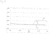
- a solid line the course of the respective size in a performance-optimized profile 50 is shown in each case.
- the deviating profile of the respective size is shown in dashed line, as it is present in a sound-optimized profile 52.
- Fig. 8 shows a relative nose radius of the rotor blade 4. As indicated by an arrow, the relative nose radius is raised in the sound-optimized profile 52. The changes are made from a relative blade length r / R of about 0.9.
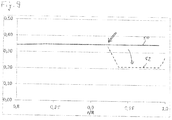
- Fig. 9 shows a relative maximum thickness of the rotor blade 4.
- the arrow indicates that the maximum thickness of the rotor blade 4 in the rotor blade end region 20 is reduced.
- a position of the maximum profile thickness migrates in the direction of the rotor blade nose 16. This position is for example at the edge shown with a double arrow, with a relative blade length of about 0.9, from which a change in the sound-optimized rotor blade profile 52 is made.
- Fig. 10 shows a maximum curvature of the rotor blade 4.
- the maximum curvature of the profile is reduced. This change is made from a relative blade length r / R of about 0.92. It is further provided that at the rotor blade tip 8, so a relative length of 1, the maximum curvature drops to zero.
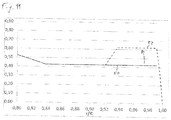
- Fig. 11 shows a maximum curvature of the rotor blade 4. As indicated by an arrow, the maximum curvature is raised in the rotor blade end portion 20, it migrates in the direction of the rotor blade trailing edge 18. At the rotor blade tip 8, the maximum curvature drops, for example to zero.
- the rotor blade 4 is approximately in Fig. 12 shown rotor blade profile.
Abstract
Die Erfindung betrifft ein Rotorblatt (4) einer Windenergieanlage (2), mit einem Rotorblatt (4) sowie ein Verfahren zum Herstellen eines Rotorblatts (4). Ausgehend von einem leistungsoptimierten Profil (50) wird ein schalloptimiertes Profil (52) bereitgestellt, indem in einem Rotorblattendbereich (20) zumindest eine der folgenden Maßnahmen ergriffen wird: Vergrößerung eines Radius des Profils an der Rotorblattnase (16), Verschiebung einer Position, an der eine maximale Profildicke vorliegt in Richtung der Rotorblattnase (16), Verringerung einer maximalen Wölbung des Profils und/oder Verschiebung einer Position, an der eine maximale Wölbung des Profils des Rotorblatts (4) vorliegt in Richtung der Rotorblatthinterkante (18).The invention relates to a rotor blade (4) of a wind energy plant (2), comprising a rotor blade (4) and a method for producing a rotor blade (4). Based on a performance-optimized profile (50), a sound-optimized profile (52) is provided by at least one of the following measures being taken in a rotor blade end region (20): increasing a radius of the profile on the rotor blade nose (16), shifting a position at which a maximum profile thickness is present in the direction of the rotor blade nose (16), reduction of a maximum curvature of the profile and / or displacement of a position at which a maximum curvature of the profile of the rotor blade (4) is present in the direction of the rotor blade trailing edge (18).
Description
Die Erfindung betrifft ein Rotorblatt einer Windenergieanlage, wobei das Rotorblatt eine Saugseite, eine Druckseite, eine Rotorblattnase und eine Rotorblatthinterkante aufweist, welche sich zwischen einer Rotorblattwurzel und einer Rotorblattspitze erstrecken und ein Profil des Rotorblatts festlegen. Außerdem betrifft die Erfindung eine Windenergieanlage mit einem Rotorblatt und ein Verfahren zum Herstellen eines Rotorblatts einer Windenergieanlage, wobei das Rotorblatt eine Saugseite, eine Druckseite, eine Rotorblattnase und eine Rotorblatthinterkante aufweist, welche sich zwischen einer Rotorblattwurzel und einer Rotorblattspitze erstrecken und ein Profil des Rotorblatts festlegen.The invention relates to a rotor blade of a wind energy plant, wherein the rotor blade has a suction side, a pressure side, a rotor blade nose and a rotor blade trailing edge, which extend between a rotor blade root and a rotor blade tip and define a profile of the rotor blade. In addition, the invention relates to a wind turbine with a rotor blade and a method for producing a rotor blade of a wind turbine, wherein the rotor blade has a suction side, a pressure side, a rotor blade nose and a rotor blade trailing edge, which extend between a rotor blade root and a rotor blade tip and define a profile of the rotor blade ,
Die Rotorblätter einer Windenergieanlage umfassen stets eine Saugseite und eine Druckseite, welche sich vielfach auf der Außenseite einer Saugseitenschale und einer Druckseitenschale erstrecken. Im Bereich einer Rotorblattnase sowie einer Rotorblatthinterkante sind die Saugseitenschale und die Druckseitenschale zusammengefügt, beispielsweise verklebt. Es entsteht ein Rotorblatt, welches sich ausgehend von einer Rotorblattwurzel, an der es mit der Nabe einer Windenergieanlage verbunden ist, bis zur Rotorblattspitze erstreckt. Die Formen der Saugseite, Druckseite sowie der Rotorblattnase und Rotorblatthinterkante definieren das Profil des Rotorblatts.The rotor blades of a wind turbine always comprise a suction side and a pressure side, which often extend on the outside of a suction side shell and a pressure side shell. In the area of a rotor blade nose and a rotor blade trailing edge, the suction side shell and the pressure side shell are joined together, for example glued. The result is a rotor blade, which extends from a rotor blade root, where it is connected to the hub of a wind turbine, to the rotor blade tip. The shapes of the suction side, pressure side and the rotor blade nose and rotor blade trailing edge define the profile of the rotor blade.
Der Ertrag einer Windenergieanlage ist wesentlich durch das Profil ihrer Rotorblätter bestimmt. Aus diesem Grund werden Rotorblätter im Hinblick auf eine optimale Leistungsausbeute hinsichtlich ihres Profils optimiert. Unvermeidbar treten jedoch im Betrieb einer Windenergieanlage Strömungsgeräusche an den Rotorblättern auf. Aus Lärmschutzgründen sind daher Mindestabstände, beispielsweise zu Wohngebieten oder anderen Schutzbereichen, einzuhalten. Dies schränkt die möglichen Standorte ein, an denen die betreffende Windenergieanlage eingesetzt werden kann.The yield of a wind turbine is essentially determined by the profile of its rotor blades. For this reason, rotor blades are optimized in terms of their profile for optimum performance. Inevitably, however, flow noise occurs on the rotor blades during operation of a wind power plant. For noise protection reasons, therefore, minimum distances, for example to residential areas or other protection areas, must be observed. This limits the possible locations where the wind turbine in question can be used.
Eine Maßnahme zum Reduzieren der Geräuschemission eines Rotorblatts besteht darin, dieses mit Hinterkantenzacken, sog. "Serrations", zu versehen. Serrations werden in einem äußeren Abschnitt des Rotorblatts an dessen Hinterkante vorgesehen. Ein entsprechendes Rotorblatt ist beispielsweise aus
Es ist eine Aufgabe der Erfindung, ein Rotorblatt einer Windenergieanlage, eine Windenergieanlage sowie ein Verfahren zum Herstellen eines Rotorblatts einer Windenergieanlage anzugeben, wobei das Rotorblatt eine geringere Schallemission aufweisen soll.It is an object of the invention to provide a rotor blade of a wind turbine, a wind turbine and a method for producing a rotor blade of a wind turbine, wherein the rotor blade is to have a lower noise emission.
Die Aufgabe wird gelöst durch ein Rotorblatt einer Windenergieanlage, wobei das Rotorblatt eine Saugseite, eine Druckseite, eine Rotorblattnase und eine Rotorblatthinterkante aufweist, welche sich zwischen einer Rotorblattwurzel und einer Rotorblattspitze erstrecken und ein Profil des Rotorblatts festlegen, wobei das Rotorblatt dadurch fortgebildet ist, dass es ein schalloptimiertes Profil aufweist, welches ausgehend von einem angenommenen leistungsoptimierten Profil, welches im Hinblick auf eine Leistungsausbeute des Rotorblatts aerodynamisch optimiert ist, zum Reduzieren der Schallemission des Rotorblatts in einem Rotorblattendbereich, der die Rotorblattspitze umfasst, durch zumindest eine der folgenden Maßnahmen verändert ist:
- a) Vergrößerung eines Radius des Profils an der Rotorblattnase,
- b) Verschiebung einer Position, an der eine maximale Profildicke vorliegt in Richtung der Rotorblattnase,
- c) Verringerung einer maximalen Wölbung des Profils,
- d) Verschiebung einer Position, an der eine maximale Wölbung des Profils des Rotorblatts vorliegt in Richtung der Rotorblatthinterkante.
- a) enlargement of a radius of the profile on the rotor blade nose,
- b) displacement of a position at which there is a maximum profile thickness in the direction of the rotor blade nose,
- c) reduction of a maximum curvature of the profile,
- d) displacement of a position at which a maximum curvature of the profile of the rotor blade is present in the direction of the rotor blade trailing edge.
Vorteilhaft reduzieren die genannten Maßnahmen zur Veränderung des aerodynamischen Profils des Rotorblatts im Rotorblattendbereich den Schallleistungspegel der Windenergieanlage. Für eine solche Windenergieanlage können geringere maximale Rotorschallleistungspegel garantiert werden, ohne dass der Schallleistungspegel durch Absenken der Blattspitzengeschwindigkeit reduziert werden muss. Letztere Maßnahme ist nämlich stets mit Leistungseinbußen verbunden und wird in sog. schallreduzierten Betriebsweisen ergriffen. Für eine Windenergieanlage, die mit Rotorblättern gemäß Aspekten der Erfindung versehen ist, können geringere maximale Rotorschallleistungspegel garantiert werden, so dass sie auch an Standorten eingesetzt werden kann, an denen herkömmliche Anlagen aufgrund ihrer zu hohen Schallemissionen nicht aufgestellt werden können oder zumindest zeitweise in schallreduzierten Betriebsarten betrieben werden müssen. Da vorteilhaft auf schallreduzierten Betriebsarten verzichtet wird, steigt außerdem der Ertrag der Windenergieanlage.Advantageously, the measures mentioned for changing the aerodynamic profile of the rotor blade in the rotor blade end region reduce the sound power level of the wind energy plant. For such a wind turbine lower maximum rotor sound power levels can be guaranteed without having to reduce the sound power level by lowering the blade tip speed. The latter measure is always associated with performance losses and is taken in so-called. Sound-reduced operations. For a wind turbine provided with rotor blades according to aspects of the invention, lower maximum Rotor sound power level can be guaranteed, so that it can also be used in locations where conventional systems can not be installed due to their high noise emissions or at least temporarily operated in low-noise modes. Since it is advantageously dispensed with reduced-noise modes, also increases the yield of the wind turbine.
Das leistungsoptimierte Profil des Rotorblatts wird beispielsweise durch numerische Simulation oder durch praktische Versuche, beispielsweise im Windkanal, ermittelt. Ausgehend von diesem im Hinblick auf eine Leistungsausbeute des Rotorblatts aerodynamisch optimierten Profil werden gemäß Aspekten der Erfindung eine oder mehrere der zuvor genannten Maßnahmen ergriffen. Es hat sich als vorteilhaft herausgestellt, im äußeren Bereich des Rotorblatts, nämlich im Rotorblattendbereich, einen Übergang auf ein schalloptimiertes Blattspitzenprofil vorzunehmen, welches auch ohne Hinterkantenzacken niedrige Schallleistungspegel liefert. Das schalloptimierte Profil ist insbesondere auf turbulente Umströmung optimiert und ausgelegt. Dabei ist es ein Ziel, die Verdrängungsdicke an der Hinterkante zu minimieren. Dies wird durch die zuvor genannten Maßnahmen, ausgehend von dem leistungsoptimierten Profil, erreicht.The performance-optimized profile of the rotor blade is determined, for example, by numerical simulation or by practical tests, for example in the wind tunnel. Starting from this aerodynamically optimized profile with regard to a power output of the rotor blade, one or more of the aforementioned measures are taken in accordance with aspects of the invention. It has proven to be advantageous to make a transition to a sound-optimized blade tip profile in the outer region of the rotor blade, namely in the rotor blade end region, which delivers low sound power level even without trailing edge spikes. The sound-optimized profile is optimized and designed especially for turbulent flow around. It is a goal to minimize the displacement thickness at the trailing edge. This is achieved by the aforementioned measures, starting from the performance-optimized profile.
Der Rotorblattendbereich beginnt beispielsweise bei 80%, 85% oder 90% der relativen Blattlänge. Unter der relativen Blattlänge wird dabei der Quotient aus der relativen Position in Längsrichtung des Rotorblatts geteilt durch den Rotorradius verstanden. Beispielsweise erstreckt sich der Rotorblattendbereich, von der Rotorblattspitze aus betrachtet, in etwa 3 m bis 4 m in Richtung der Rotorblattwurzel. Mit anderen Worten weist also das Rotorblatt in seinen äußersten 3 m bis 4 m ein schalloptimiertes und kein leistungsoptimiertes Profil auf.For example, the rotor blade end region starts at 80%, 85%, or 90% of the relative blade length. The relative blade length is understood to mean the quotient of the relative position in the longitudinal direction of the rotor blade divided by the rotor radius. For example, as viewed from the rotor blade tip, the rotor blade end region extends approximately 3 m to 4 m in the direction of the rotor blade root. In other words, therefore, the rotor blade in its outermost 3 m to 4 m on a sound-optimized and no performance-optimized profile.
Gemäß einer vorteilhaften Ausführungsform ist vorgesehen, dass das Rotorblatt dadurch fortgebildet ist, dass es in einem mittleren Abschnitt Hinterkantenzacken (Serrations) an der Rotorblatthinterkante aufweist, wobei im Rotorblattendbereich keine Hinterkantenzacken vorhanden sind, und wobei sich der mittlere Abschnitt ausgehend von dem Rotorblattendbereich in Richtung der Rotorblattwurzel erstreckt.According to an advantageous embodiment, it is provided that the rotor blade is formed by having trailing edge serrations on the rotor blade trailing edge in a middle section, no trailing edge serrations being present in the rotor blade end region, and the middle section starting from the rotor blade end region in the direction of the rotor blade end Rotor blade root extends.
Hinterkantenzacken, sog. Serrations, sind als Mittel zur Reduktion des Strömungslärms von Rotorblättern an sich bekannt. Indem diese nun, wie gemäß Aspekten der Erfindung vorgeschlagen, lediglich im mittleren Abschnitt des Rotorblatts eingesetzt werden, ist der Transport des Rotorblatts wesentlich einfacher. Sind nämlich auch am äußeren Ende des Rotorblattes Hinterkantenzacken vorhanden, so besteht beim Transport stets die Gefahr, dass die Hinterkantenzacken beschädigt werden. Indem auf Hinterkantenzacken im Rotorblattendbereich verzichtet wird, ist ein herkömmlicher Transport des Rotorblatts möglich, so wie er von Rotorblättern bekannt ist, die keine Hinterkantenzacken aufweisen. Die Rotorblattspitze kann gefahrlos in Taschen aufgenommen werden; die Gefahr die Hinterkantenzacken während des Transports des Rotorblatts zu beschädigen, ist wesentlich verringert. Außerdem kann auf konventionelle Vorrichtungen und Infrastruktur zum Transport des Rotorblatts zurückgegriffen werden.Trailing serrations, so-called serrations, are known per se as means for reducing the flow noise of rotor blades. By now being used only in the middle section of the rotor blade, as proposed in accordance with aspects of the invention, the transport of the rotor blade is considerably simpler. If trailing edge points are also present at the outer end of the rotor blade, there is always the danger during transport that the trailing edge points are damaged. By dispensing with trailing edge serrations in the rotor blade end region, a conventional transport of the rotor blade is possible, as is known from rotor blades which have no trailing edge serrations. The rotor blade tip can be safely stored in pockets; the danger of damaging the trailing edge spikes during the transport of the rotor blade is substantially reduced. In addition, conventional devices and infrastructure for transporting the rotor blade can be used.
Bevorzugt erstrecken sich die Hinterkantenzacken im gesamten mittleren Abschnitt. Gemäß einem weiteren Ausführungsbeispiel ist vorgesehen, dass sich die Hinterkantenzacken abschnittsweise im mittleren Abschnitt des Rotorblatts erstrecken. Ferner weisen die Hinterkantenzacken insbesondere ein Längen-zu-Breiten-Verhältnis von größer als zwei auf. Sie sind also zumindest doppelt so lang wie breit.Preferably, the trailing edge spans extend throughout the central portion. According to a further embodiment, it is provided that the trailing edge serrations extend in sections in the central portion of the rotor blade. In addition, the trailing edge spikes have, in particular, a length-to-width ratio of greater than two. So they are at least twice as long as they are wide.
Gemäß einer weiteren Ausführungsform ist das Rotorblatt ferner dadurch fortgebildet, dass die Hinterkantenzacken
- a) eine maximale Länge von weniger als 20% einer Länge der Profilsehne an der zugehörigen Längsposition des Rotorblatts aufweisen,
und/oder - b) eine Materialstärke von 5 mm oder weniger aufweisen,
und/oder - c) gegenüber einer Richtung der Profilsehne um einen Winkel von 5° oder weniger geneigt sind.
- a) have a maximum length of less than 20% of a length of chord at the associated longitudinal position of the rotor blade,
and or - b) have a material thickness of 5 mm or less,
and or - c) are inclined with respect to a direction of the chord by an angle of 5 ° or less.
Die Hinterkantenzacken werden möglichst dünn ausgeführt. Sie sind insbesondere stufenfrei mit dem Profil des Rotorblatts verklebt. Der Winkel zwischen den Hinterkantenzacken und der Profilsehne wird jeweils in einer gemeinsamen Profilebene gemessen. Durch einen Anstellwinkel der Hinterkantenzacken (Winkel zwischen der Richtung der Profilsehne und der Ebene, in der sich die Hinterkantenzacken an dieser Längsposition des Rotorblatts erstrecken), der einen Wert von 5° oder weniger aufweist, wird der Arbeitspunkt des Profils nur unwesentlich verändert, der durch die Serrations erzeugte zusätzliche Auftrieb wird begrenzt.The trailing edges are made as thin as possible. They are particularly glued step-free with the profile of the rotor blade. The angle between the trailing edge teeth and the chord is in each case in a common profile plane measured. By an angle of incidence of the trailing edge prongs (angle between the direction of the chord and the plane in which the trailing edge spikes extend at this longitudinal position of the rotor blade), which has a value of 5 ° or less, the operating point of the profile is changed only insignificantly by the serration generated additional buoyancy is limited.
Gemäß einer Ausführungsform ist ferner vorgesehen, dass im mittleren Abschnitt des Rotorblatts ein Verhältnis von Profildicke zu Sehnenlänge kleiner als 0,24 ist. Ferner ist das Rotorblatt gemäß einer weiteren Ausführungsform dadurch fortgebildet, dass sich der mittlere Abschnitt ausgehend von einer ersten Profilebene in Richtung der Rotorblattspitze erstreckt, wobei bei Nennleistung der Windenergieanlage das Rotorblatt in der ersten Profilebene mit einer Relativgeschwindigkeit von 55 m/s überströmt wird.According to one embodiment, it is further provided that in the middle section of the rotor blade, a ratio of profile thickness to chord length is less than 0.24. Furthermore, according to a further embodiment, the rotor blade is developed in that the middle section extends starting from a first profile plane in the direction of the rotor blade tip, wherein at nominal power of the wind turbine, the rotor blade is overflowed in the first profile plane with a relative velocity of 55 m / s.
Die Rotorblattspitze trägt, da diese mit der größten Relativgeschwindigkeit überströmt wird, wesentlich zur Schallemission des Rotorblatts bei. Eine Veränderung des Profils des Rotorblatts im Rotorblattendbereich von einem leistungsoptimalen auf ein schalloptimales Profil ist besonders wirkungsvoll. Es hat sich herausgestellt, dass besonders gute Ergebnisse erzielt werden, wenn diese Änderungen ab einem Bereich vorgenommen werden, in dem das Rotorblatt mit Relativgeschwindigkeiten von 55 m/s und mehr überströmt wird.The rotor blade tip, since it is overflowed with the greatest relative speed, contributes significantly to the noise emission of the rotor blade. A change in the profile of the rotor blade in the rotor blade end region from a performance-optimized to a sound-optimized profile is particularly effective. It has been found that particularly good results are achieved when these changes are made from a range in which the rotor blade with relative velocities of 55 m / s and more is overflowed.
Gemäß einer weiteren Ausführungsform ist ferner vorgesehen, dass das Rotorblatt in einem Blattwurzelbereich auf der Saugseite Wirbelgeneratoren aufweist, wobei sich der Blattwurzelbereich ausgehend von der Rotorblattwurzel bis zu einer zweiten Profilebene erstreckt, und wobei bei Nennleistung der Windenergieanlage das Rotorblatt in der zweiten Profilebene mit einer Relativgeschwindigkeit von 30 m/s überströmt wird.According to a further embodiment, it is further provided that the rotor blade has vortex generators in a blade root area on the suction side, wherein the blade root area extends from the rotor blade root to a second profile plane, and wherein at nominal power of the wind turbine, the rotor blade in the second profile plane with a relative velocity of 30 m / s is overflowed.
Eine aerodynamisch sowie strukturell hocheffiziente Blattwurzel, welche mit Wirbelgeneratoren (auch als Vortex-Generatoren bezeichnet) versehen ist, erstreckt sich gemäß den genannten Ausführungsformen bis in eine Profilebene, in der das Rotorblatt mit einer Relativgeschwindigkeit von 30 m/s überströmt wird. Es hat sich herausgestellt, dass der Einsatz von Vortex-Generatoren in Bereichen des Rotorblatts, welche weiter in Richtung Rotorblattspitze liegen, im Hinblick auf die Schallemission des Rotorblatts keine nennenswerte weitere Verbesserung bringt.An aerodynamically and structurally highly efficient blade root, which is provided with vortex generators (also referred to as vortex generators), according to the embodiments mentioned, extends into a profile plane in which the rotor blade is overflowed at a relative speed of 30 m / s. It has been found that the use of vortex generators in areas of the rotor blade, which lie further in the direction of the rotor blade tip, with respect to the sound emission of the rotor blade brings no appreciable further improvement.
Ferner ist das Rotorblatt dadurch fortgebildet, dass das Rotorblatt an der Rotorblattnase einen Erosionsschutz aufweist, wobei der Erosionsschutz mit einer Stufenhöhe von weniger als 0,2 mm in eine Oberfläche des Rotorblatts integriert ist.Furthermore, the rotor blade is developed by virtue of the fact that the rotor blade has erosion protection on the rotor blade nose, the erosion protection having a step height of less than 0.2 mm being integrated into a surface of the rotor blade.
Schließlich ist das Rotorblatt gemäß einer weiteren Ausführungsform dadurch fortgebildet, dass es auf der Saugseite einen tangentialen Ausblasschlitz aufweist, wobei sich der Ausblasschlitz ausgehend von einer dritten Profilebene in Richtung der Rotorblattspitze erstreckt und die dritte Profilebene an einer relativen Blattlänge von zumindest näherungsweise 80% angeordnet ist.Finally, according to a further embodiment, the rotor blade is developed in that it has a tangential blow-out slot on the suction side, wherein the blow-out slot extends from a third profile plane in the direction of the rotor blade tip and the third profile plane is arranged at a relative blade length of at least approximately 80% ,
Sowohl die stufenfreie oder annähernd stufenfreie Integration eines Erosionsschutzes in die Oberfläche des Rotorblatts als auch die Integration eines Ausblasschlitzes, insbesondere an der genannten Position, führen zu einer weiteren Verringerung des Schallleistungspegels des Rotorblatts.Both the step-free or almost step-free integration of erosion protection in the surface of the rotor blade and the integration of a blow-out slot, in particular at said position, lead to a further reduction of the sound power level of the rotor blade.
Die Aufgabe wird außerdem gelöst durch eine Windenergieanlage mit einem Rotorblatt gemäß einem oder mehreren der zuvor genannten erfindungsgemäßen Aspekte. Auf eine solche Windenergieanlage treffen die bereits zuvor im Hinblick auf das Rotorblatt erwähnten Vorteile in gleicher oder ähnlicher Weise zu, so dass auf Wiederholungen verzichtet wird.The object is also achieved by a wind turbine with a rotor blade according to one or more of the aforementioned aspects of the invention. On such a wind turbine meet the advantages already mentioned above with regard to the rotor blade in the same or similar manner, so that it is not necessary to repeat.
Ferner wird die Aufgabe gelöst durch ein Verfahren zum Herstellen eines Rotorblatts einer Windenergieanlage, wobei das Rotorblatt eine Saugseite, eine Druckseite, eine Rotorblattnase und eine Rotorblatthinterkante aufweist, welche sich zwischen einer Rotorblattwurzel und einer Rotorblattspitze erstrecken und ein Profil des Rotorblatts festlegen, wobei das Verfahren durch die folgenden Schritte fortgebildet ist:
- I) Bereitstellen eines leistungsoptimierten Profils des Rotorblatts, wobei das leistungsoptimierte Profil im Hinblick auf eine Leistungsausbeute des Rotorblatts aerodynamisch optimiert ist,
- II) Verändern des leistungsoptimierten Profils, um in einem Rotorblattendbereich ein schalloptimiertes Profil zu erhalten, zum Reduzieren einer Schallemission des Rotorblatts, wobei ausgehend von dem leistungsoptimierten Profil im Rotorblattendbereich, der die Rotorblattspitze umfasst, zumindest eine der folgenden Maßnahmen durchgeführt wird:
- a) Vergrößern eines Radius des Profils an der Rotorblattnase,
- b) Verschieben einer Position, an der eine maximale Profildicke vorliegt in Richtung der Rotorblattnase,
- c) Verringern einer maximalen Wölbung des Profils,
- d) Verschieben einer Position, an der eine maximale Wölbung des Profils des Rotorblatts vorliegt in Richtung der Rotorblatthinterkante,
- III) Herstellen des Rotorblatts mit dem schalloptimierten Profil im Rotorblattendbereich.
- I) providing a performance-optimized profile of the rotor blade, wherein the power-optimized profile is aerodynamically optimized with regard to a power output of the rotor blade,
- II) Modifying the power-optimized profile to obtain a sound optimized profile in a rotor blade end area to reduce acoustic emissions of the rotor blade, wherein, starting from the power-optimized profile in the rotor blade end region, which comprises the rotor blade tip, at least one of the following measures is carried out:
- a) increasing a radius of the profile on the rotor blade nose,
- b) shifting a position at which there is a maximum profile thickness in the direction of the rotor blade nose,
- c) reducing a maximum curvature of the profile,
- d) shifting a position at which a maximum curvature of the profile of the rotor blade is present in the direction of the rotor blade trailing edge,
- III) Production of the rotor blade with the sound-optimized profile in the rotor blade end region.
Auch auf das Verfahren zum Herstellen eines Rotorblatts treffen gleiche oder ähnliche Vorteile und Aspekte zu, wie sie bereits im Hinblick auf das Rotorblatt erwähnt wurden. Das Verfahren ist außerdem mit geringem Aufwand durchführbar, da ausgehend von einem leistungsoptimierten Profil, welches zum Herstellen des Rotorblatts vorhanden ist, lediglich geringe Profiländerungen vorgenommen werden müssen. Diese lassen sich mit geringem Aufwand in den vorhandenen Herstellungsprozess integrieren.Also, the method of manufacturing a rotor blade has the same or similar advantages and aspects as already mentioned with respect to the rotor blade. The method is also feasible with little effort, since starting from a performance-optimized profile, which is available for producing the rotor blade, only slight profile changes must be made. These can be integrated with little effort into the existing manufacturing process.
Das Verfahren ist ferner dadurch fortgebildet, dass das Rotorblatt in einem mittleren Abschnitt mit Hinterkantenzacken (Serrations) an der Rotorblatthinterkante versehen wird, wobei im Rotorblattendbereich keine Hinterkantenzacken vorgesehen werden, und wobei sich der mittlere Abschnitt ausgehend von dem Rotorblattendbereich in Richtung der Rotorblattwurzel erstreckt.The method is further developed by providing the rotor blade in a central portion with serrations at the rotor blade trailing edge, wherein no trailing edge serrations are provided in the rotor blade end region, and wherein the central portion extends from the rotor blade end portion toward the rotor blade root.
Gemäß einer weiteren Ausführungsform ist ferner vorgesehen, dass das Verfahren dadurch fortgebildet ist, dass die Hinterkantenzacken vorgesehen werden, die
- a) eine maximale Länge von weniger
als 20% einer Länge der Profilsehne an der zugehörigen Längsposition des Rotorblatts aufweisen,
und/oder - b)
eine Materialstärke von 5 mm oder weniger aufweisen,
und/oder - c) gegenüber einer Richtung der Profilsehne um
einen Winkel von 5° oder weniger geneigt sind.
- a) have a maximum length of less than 20% of a length of chord at the associated longitudinal position of the rotor blade,
and or - b) have a material thickness of 5 mm or less,
and or - c) with respect to a direction of the chord of the profile at an angle of 5 ° or less are inclined.
Gemäß einer weiteren Ausführungsform ist vorgesehen, dass ein mittlerer Abschnitt vorgesehen wird, der sich ausgehend von einer ersten Profilebene in Richtung der Rotorblattspitze erstreckt, wobei bei Nennleistung der Windenergieanlage das Rotorblatt in der ersten Profilebene mit einer Relativgeschwindigkeit von 55 m/s überströmt wird. Insbesondere ist das Verfahren dadurch fortgebildet, dass das Rotorblatt in einem Blattwurzelbereich auf der Saugseite mit Wirbelgeneratoren versehen wird, wobei sich der Blattwurzelbereich ausgehend von der Rotorblattwurzel bis zu einer zweiten Profilebene erstreckt, und wobei bei Nennleistung der Windenergieanlage das Rotorblatt in der zweiten Profilebene mit einer Relativgeschwindigkeit von 30 m/s überströmt wird.According to a further embodiment, it is provided that a middle section is provided, which extends from a first profile plane in the direction of the rotor blade tip, wherein at nominal power of the wind turbine, the rotor blade is flowed over in the first profile plane with a relative velocity of 55 m / s. In particular, the method is further developed in that the rotor blade is provided in a blade root area on the suction side with vortex generators, wherein the blade root area extending from the rotor blade root to a second profile plane, and wherein at rated power of the wind turbine, the rotor blade in the second profile plane with a Relative speed of 30 m / s is overflowed.
Ferner ist gemäß einer Ausführungsform vorgesehen, dass das Rotorblatt auf der Saugseite mit einem tangentialen Ausblasschlitz versehen wird, wobei sich der Ausblasschlitz ausgehend von einer dritten Profilebene in Richtung der Rotorblattspitze erstreckt und die dritte Profilebene an einer relativen Blattlänge von zumindest näherungsweise 80% angeordnet ist.Furthermore, according to one embodiment, it is provided that the rotor blade is provided on the suction side with a tangential blow-out slot, wherein the blow-out slot extends from a third profile plane in the direction of the rotor blade tip and the third profile plane is arranged at a relative blade length of at least approximately 80%.
Gemäß weiterer Ausführungsformen ist vorgesehen, dass im mittleren Abschnitt des Rotorblatts ein Verhältnis von Profildicke zu Sehnenlänge von kleiner als 0,24 vorgesehen wird. Ferner ist insbesondere vorgesehen, dass das Rotorblatt an der Rotorblattnase mit einem Erosionsschutz versehen wird, wobei der Erosionsschutz mit einer Stufenhöhe von weniger als 0,2 mm in eine Oberfläche des Rotorblatts integriert wird.According to further embodiments, it is provided that a ratio of profile thickness to chord length of less than 0.24 is provided in the middle section of the rotor blade. Furthermore, it is provided in particular that the rotor blade is provided with erosion protection on the rotor blade nose, the erosion protection being integrated with a step height of less than 0.2 mm into a surface of the rotor blade.
Weitere Merkmale der Erfindung werden aus der Beschreibung erfindungsgemäßer Ausführungsformen zusammen mit den Ansprüchen und den beigefügten Zeichnungen ersichtlich. Erfindungsgemäße Ausführungsformen können einzelne Merkmale oder eine Kombination mehrerer Merkmale erfüllen.Further features of the invention will become apparent from the description of embodiments according to the invention together with the claims and the accompanying drawings. Embodiments of the invention may satisfy individual features or a combination of several features.
Die Erfindung wird nachstehend ohne Beschränkung des allgemeinen Erfindungsgedankens anhand von Ausführungsbeispielen unter Bezugnahme auf die Zeichnungen beschrieben, wobei bezüglich aller im Text nicht näher erläuterten erfindungsgemäßen Einzelheiten ausdrücklich auf die Zeichnungen verwiesen wird. Es zeigen:
- Fig. 1
- eine Windenergieanlage in schematisch vereinfachter Ansicht,
- Fig. 2
- eine schematisch vereinfachte Draufsicht auf eine Saugseite eines Rotorblatts,
- Fig. 3
- eine schematisch vereinfachte Querschnittsansicht entlang der Ebene III-III in
Fig. 2 , - Fig. 4
- eine schematisch vereinfachte Querschnittsansicht entlang der Ebene IV-IV in
Fig. 2 , - Fig. 5
- eine schematisch vereinfachte Querschnittsansicht im Bereich der Rotorblatthinterkante
- Fig. 6
- eine schematisch vereinfachte Draufsicht auf einen Abschnitt von Hinterkantenzacken
- Fig. 7, 7a
- schematisch vereinfachte Ansichten des Rotorblattprofils im Rotorblattendbereich,
- Fig. 8
- ein relativer Radius eines schalloptimierten Rotorblatts an der Vorderkante, aufgetragen über einer relativen Blattlänge,
- Fig. 9
- eine relative Dicke des Rotorblattprofils, aufgetragen über der relativen Länge des Rotorblatts,
- Fig. 10
- eine maximale Distanz der Skelettlinie des Rotorblatts zur Sehne des Rotorblatts, aufgetragen über der relativen Länge,
- Fig. 11
- eine maximale Wölbung des Rotorblattprofils, aufgetragen über der relativen Länge des Rotorblatts und
- Fig. 12
- ein schematisch vereinfachtes Profil des Rotorblatts in der in
Fig. 2 mit XII-XII bezeichneten Ebene.
- Fig. 1
- a wind energy plant in a schematically simplified view,
- Fig. 2
- a schematically simplified plan view of a suction side of a rotor blade,
- Fig. 3
- a schematically simplified cross-sectional view along the plane III-III in
Fig. 2 . - Fig. 4
- a schematically simplified cross-sectional view along the plane IV-IV in
Fig. 2 . - Fig. 5
- a schematically simplified cross-sectional view in the region of the rotor blade trailing edge
- Fig. 6
- a simplified schematic plan view of a portion of trailing edge teeth
- Fig. 7, 7a
- schematically simplified views of the rotor blade profile in the rotor blade end,
- Fig. 8
- a relative radius of a sound-optimized rotor blade at the leading edge, plotted over a relative blade length,
- Fig. 9
- a relative thickness of the rotor blade profile, plotted over the relative length of the rotor blade,
- Fig. 10
- a maximum distance of the skeleton line of the rotor blade to the chord of the rotor blade, plotted over the relative length,
- Fig. 11
- a maximum curvature of the rotor blade profile, plotted over the relative length of the rotor blade and
- Fig. 12
- a schematically simplified profile of the rotor blade in the in
Fig. 2 level designated XII-XII.
In den Zeichnungen sind jeweils gleiche oder gleichartige Elemente und/oder Teile mit denselben Bezugsziffern versehen, so dass von einer erneuten Vorstellung jeweils abgesehen wird.In the drawings, the same or similar elements and / or parts are provided with the same reference numerals, so that apart from a new idea each.
Die Rotorblätter 4 umfassen jeweils eine Saugseite 14 (in
Zusätzlich zu dieser Veränderung des Rotorblattprofils im Rotorblattendbereich 20 werden weitere optionale Maßnahmen ergriffen, um den Schallleistungspegel des Rotorblatts 4 zu senken.In addition to this change in the rotor blade profile in the rotor
Beispielsweise wird das Rotorblatt 4 in einem Blattwurzelbereich 22 auf seiner Saugseite 14 mit Wirbelgeneratoren 24 versehen.For example, the
Wie
In Richtung der Rotorblattspitze 8 schließt sich an den Blattwurzelbereich 22 ein Leistungsbereich 32 an. Dieser erstreckt sich ausgehend von der zweiten Profilebene 30 in Richtung der Rotorblattspitze 8 bis zu einer ersten Profilebene 34, auf die später Bezug genommen werden soll. Im Leistungsbereich 32 weist das Rotorblatt 4 ein leistungsoptimiertes Profil auf. Es werden außerdem in diesem Bereich keine Maßnahmen zur Schalloptimierung des Rotorblatts 4 vorgenommen.In the direction of the
An den Leistungsbereich 32 schließt sich in Richtung der Rotorblattspitze 8 ein mittlerer Abschnitt 36 an. Der mittlere Abschnitt 36 erstreckt sich ausgehend vom Rotorblattendbereich 20 in Richtung der Rotorblattwurzel 6 bis zu der ersten Profilebene 34. In der ersten Profilebene 34 wird das Rotorblatt 4 bei Nennleistung der Windenergieanlage 2 mit eine Relativgeschwindigkeit von 55 m/s überströmt.The
Im mittleren Abschnitt 36 des Rotorblatts 4 ist dieses an der Rotorblatthinterkante 18 mit Hinterkantenzacken 38 versehen. Sowohl im Rotorblattendbereich 20, als auch in dem weiter in Richtung der Blattwurzel 6 gelegenen Leistungsbereich 32, weist das Rotorblatt 4 keine Hinterkantenzacken 38 auf. Die Hinterkantenzacken 38, auch als Serrations bezeichnet, verringern die Schallemission des Rotorblatts 4.In the
Im mittleren Abschnitt 36 des Rotorblatts 4 ist das Profil außerdem beispielsweise so gewählt, dass ein Verhältnis der Profildicke PD zur Sehnenlänge L2 kleiner als 0,24 ist. Ferner ist das Rotorblatt 4 beispielsweise an der Rotorblattnase 16 mit einem Erosionsschutz 44 versehen. Der Erosionsschutz 44 ist beispielsweise mit einer Stufenhöhe von weniger als 0,2 mm in eine Oberfläche des Rotorblatts 4 integriert.In the
Als weitere Maßnahme zur Verringerung der Schallemission ist das Rotorblatt 4 beispielsweise mit einem tangentialen Ausblasschlitz 46 (vgl.
Im Folgenden wird unter Bezugnahme auf die
- a) Der Radius des Profils an der Rotorblattnase 16 ist vergrößert.
- b) Eine Position, an der eine maximale Profildicke vorliegt, ist in
Richtung der Rotorblattnase 16 verschoben. - c) Eine maximale Wölbung des Profils ist verringert.
- d) Eine Position, an der eine maximale Wölbung des Rotorblatts 4 vorliegt, ist in
Richtung der Rotorblatthinterkante 18 verschoben.
- a) The radius of the profile on the
rotor blade nose 16 is increased. - b) A position at which there is a maximum profile thickness is shifted in the direction of the
rotor blade nose 16. - c) A maximum curvature of the profile is reduced.
- d) A position at which there is a maximum curvature of the
rotor blade 4 is shifted in the direction of the rotorblade trailing edge 18.
Die zuvor genannten Maßnahmen können einzeln oder in Kombination ergriffen werden, um die Schallemission des Rotorblatts 4 zu senken.The aforementioned measures can be taken individually or in combination in order to reduce the noise emission of the
Die einzelnen Maßnahmen werden anhand der Darstellungen in den
An der Rotorblattspitze 8, in einer Ebene die mit XII-XII in
Gemäß einem Verfahren zum Herstellen eines Rotorblatts 4 einer Windenergieanlage 2 wird zunächst ein leistungsoptimiertes Profil 50 des Rotorblatts 4 bereitgestellt. Dies erfolgt beispielsweise durch nummerische Simulation oder durch Versuche. Dieses leistungsoptimierte Profil 50 wird, um ein schalloptimiertes Profil 52 zu erhalten und die Schallemission des Rotorblatts 4 zu reduzieren, durch zumindest eine der folgenden Maßnahmen verändert:
- Vergrößern eines Radius des Profils an
der Rotorblattnase 16, Verschieben einer Position, an der eine maximale Profildicke vorliegt inRichtung der Rotorblattnase 16, Verringern einer maximalen Wölbung des Profils und/oder Verschieben einer Position, in der eine maximale Wölbung des Profils des Rotorblatts 4 vorliegt inRichtung der Rotorblatthinterkante 18. Anschließendwird das Rotorblatt 4 mit dem schalloptimierten Profil hergestellt.
- Increasing a radius of the profile on the
rotor blade nose 16, shifting a position at which there is a maximum profile thickness in the direction of therotor blade nose 16, reducing a maximum curvature of the profile and / or shifting a position in which a maximum curvature of the profile of therotor blade 4 is present in the direction of the rotorblade trailing edge 18. Subsequently, therotor blade 4 is produced with the sound-optimized profile.
Alle genannten Merkmale, auch die den Zeichnungen allein zu entnehmenden sowie auch einzelne Merkmale, die in Kombination mit anderen Merkmalen offenbart sind, werden allein und in Kombination als erfindungswesentlich angesehen. Erfindungsgemäße Ausführungsformen können durch einzelne Merkmale oder eine Kombination mehrerer Merkmale erfüllt sein. Im Rahmen der Erfindung sind Merkmale, die mit "insbesondere" oder "vorzugsweise" gekennzeichnet sind, als fakultative Merkmale zu verstehen.All mentioned features, including the drawings alone to be taken as well as individual features that are disclosed in combination with other features are considered alone and in combination as essential to the invention. Embodiments of the invention may be accomplished by individual features or a combination of several features. In the context of the invention, features which are identified by "particular" or "preferably" are to be understood as optional features.
- 22
- WindenergieanlageWind turbine
- 44
- Rotorblattrotor blade
- 66
- RotorblattwurzelRotor blade root
- 88th
- RotorblattspitzeRotor blade tip
- 1010
- Nabehub
- 1212
- Tragstruktursupporting structure
- 1414
- Saugseitesuction
- 1616
- RotorblattnaseRotor blade leading edge
- 1818
- RotorblatthinterkanteRotor blade trailing edge
- 2020
- RotorblattendbereichRotorblattendbereich
- 2222
- BlattwurzelbereichBlade root area
- 2424
- Wirbelgeneratorenvortex generators
- 2626
- Druckseitepressure side
- 2828
- HinterkantenstegTrailing edge rib
- 3030
- zweite Profilebenesecond profile level
- 3232
- Leistungsbereichpower range
- 3434
- erste Profilebenefirst profile level
- 3636
- mittlerer Abschnittmiddle section
- 3838
- HinterkantenzackenTrailing edge serrations
- 4040
- Profilsehnechord
- 4444
- Erosionsschutzerosion protection
- 4646
- Ausblasschlitzblow-out slot
- 4848
- dritte Profilebenethird profile level
- 5050
- leistungsoptimiertes Profilperformance optimized profile
- 5252
- schalloptimiertes Profilsound-optimized profile
- L1L1
- Länge der HinterkantenzackenLength of the trailing edges
- L2L2
- Länge der ProfilsehneLength of the chord
- αα
- Winkelangle
- dd
- Materialstärkematerial thickness
- bb
- Breitewidth
- PDPD
- Profildickeprofile thickness
- rr
- radiale Positionradial position
- RR
- Rotorradiusrotor radius
Claims (15)
und/oder
und/oder
and or
and or
und/oder
und/oder
and or
and or
Applications Claiming Priority (1)
| Application Number | Priority Date | Filing Date | Title |
|---|---|---|---|
| DE102015012427.7A DE102015012427A1 (en) | 2015-09-25 | 2015-09-25 | Rotor blade with a sound-optimized profile and method for producing a rotor blade |
Publications (2)
| Publication Number | Publication Date |
|---|---|
| EP3147499A1 true EP3147499A1 (en) | 2017-03-29 |
| EP3147499B1 EP3147499B1 (en) | 2020-04-08 |
Family
ID=56876958
Family Applications (1)
| Application Number | Title | Priority Date | Filing Date |
|---|---|---|---|
| EP16187323.7A Active EP3147499B1 (en) | 2015-09-25 | 2016-09-06 | Rotor blade comprising a sound optimized profile and method for manufacturing a rotor blade |
Country Status (4)
| Country | Link |
|---|---|
| EP (1) | EP3147499B1 (en) |
| DE (1) | DE102015012427A1 (en) |
| DK (1) | DK3147499T3 (en) |
| ES (1) | ES2794787T3 (en) |
Cited By (5)
| Publication number | Priority date | Publication date | Assignee | Title |
|---|---|---|---|---|
| EP3763937A1 (en) | 2019-07-11 | 2021-01-13 | FlowGen Development & Management GmbH | Rotor blade for a wind turbine and wind turbine |
| CN112585350A (en) * | 2018-08-31 | 2021-03-30 | 通用电气公司 | Silencer for wind turbine rotor blades with curved serrations |
| CN113090471A (en) * | 2019-12-23 | 2021-07-09 | 新疆金风科技股份有限公司 | Tower clearance audio monitoring system, method and device of wind generating set |
| CN113357080A (en) * | 2021-06-10 | 2021-09-07 | 中科宇能科技发展有限公司 | Wind-powered electricity generation blade ring volume control system that blows |
| US20220228551A1 (en) * | 2019-05-17 | 2022-07-21 | Wobben Properties Gmbh | Rotor blade and wind turbine |
Citations (6)
| Publication number | Priority date | Publication date | Assignee | Title |
|---|---|---|---|---|
| US20030099546A1 (en) * | 2001-11-26 | 2003-05-29 | Henrik Stiesdal | Method for improvement of the efficiency of a wind turbine rotor |
| EP1674723A2 (en) * | 2004-12-23 | 2006-06-28 | General Electric Company | Active flow modification on wind turbine blades |
| US20110142666A1 (en) | 2010-11-15 | 2011-06-16 | General Electric Company | Noise reducer for rotor blade in wind turbine |
| US20110150664A1 (en) * | 2009-12-22 | 2011-06-23 | Siegfried Mickeler | Aeroacoustic rotor blade for a wind turbine, and wind turbine equipped therewith |
| EP2682602A1 (en) * | 2011-02-28 | 2014-01-08 | Mitsubishi Heavy Industries, Ltd. | Wind turbine blade and wind-powered electricity generator provided with same |
| WO2014170232A1 (en) * | 2013-04-17 | 2014-10-23 | Lm Wp Patent Holding A/S | A wind turbine blade repair method |
Family Cites Families (7)
| Publication number | Priority date | Publication date | Assignee | Title |
|---|---|---|---|---|
| EP2631474B1 (en) * | 2010-10-22 | 2016-12-21 | Mitsubishi Heavy Industries, Ltd. | Wind turbine blade, wind power generation system including the same, and method for designing wind turbine blade |
| US8414261B2 (en) | 2011-05-31 | 2013-04-09 | General Electric Company | Noise reducer for rotor blade in wind turbine |
| US9752444B2 (en) | 2011-12-19 | 2017-09-05 | Lm Wp Patent Holding A/S | Erosion shield for a wind turbine blade |
| DE102013006203A1 (en) | 2012-04-30 | 2013-10-31 | HKB Turbinen GmbH & Co. KG | Rotor blade for wind turbine, comprises profile, which has suction side that is convexly curved in central portion having fixed radius, where central portion of suction side has length, whose projection extends to chord from leading edge |
| US10677217B2 (en) * | 2012-10-03 | 2020-06-09 | General Electric Company | Wind turbine and method of operating the same |
| US20140093380A1 (en) | 2012-10-03 | 2014-04-03 | General Electric Company | Noise reduction tab and method for wind turbine rotor blade |
| DK177928B1 (en) * | 2013-06-17 | 2015-01-19 | Envision Energy Denmark Aps | Wind turbine blade with extended shell section |
-
2015
- 2015-09-25 DE DE102015012427.7A patent/DE102015012427A1/en not_active Withdrawn
-
2016
- 2016-09-06 EP EP16187323.7A patent/EP3147499B1/en active Active
- 2016-09-06 DK DK16187323.7T patent/DK3147499T3/en active
- 2016-09-06 ES ES16187323T patent/ES2794787T3/en active Active
Patent Citations (6)
| Publication number | Priority date | Publication date | Assignee | Title |
|---|---|---|---|---|
| US20030099546A1 (en) * | 2001-11-26 | 2003-05-29 | Henrik Stiesdal | Method for improvement of the efficiency of a wind turbine rotor |
| EP1674723A2 (en) * | 2004-12-23 | 2006-06-28 | General Electric Company | Active flow modification on wind turbine blades |
| US20110150664A1 (en) * | 2009-12-22 | 2011-06-23 | Siegfried Mickeler | Aeroacoustic rotor blade for a wind turbine, and wind turbine equipped therewith |
| US20110142666A1 (en) | 2010-11-15 | 2011-06-16 | General Electric Company | Noise reducer for rotor blade in wind turbine |
| EP2682602A1 (en) * | 2011-02-28 | 2014-01-08 | Mitsubishi Heavy Industries, Ltd. | Wind turbine blade and wind-powered electricity generator provided with same |
| WO2014170232A1 (en) * | 2013-04-17 | 2014-10-23 | Lm Wp Patent Holding A/S | A wind turbine blade repair method |
Cited By (7)
| Publication number | Priority date | Publication date | Assignee | Title |
|---|---|---|---|---|
| CN112585350A (en) * | 2018-08-31 | 2021-03-30 | 通用电气公司 | Silencer for wind turbine rotor blades with curved serrations |
| US20220228551A1 (en) * | 2019-05-17 | 2022-07-21 | Wobben Properties Gmbh | Rotor blade and wind turbine |
| EP3763937A1 (en) | 2019-07-11 | 2021-01-13 | FlowGen Development & Management GmbH | Rotor blade for a wind turbine and wind turbine |
| WO2021004853A1 (en) | 2019-07-11 | 2021-01-14 | Flowgen Development & Management Gmbh | Rotor blade for a wind turbine and wind turbine |
| CN113090471A (en) * | 2019-12-23 | 2021-07-09 | 新疆金风科技股份有限公司 | Tower clearance audio monitoring system, method and device of wind generating set |
| CN113357080A (en) * | 2021-06-10 | 2021-09-07 | 中科宇能科技发展有限公司 | Wind-powered electricity generation blade ring volume control system that blows |
| CN113357080B (en) * | 2021-06-10 | 2023-02-28 | 中科宇能科技发展有限公司 | Wind-powered electricity generation blade ring volume control system that blows |
Also Published As
| Publication number | Publication date |
|---|---|
| DE102015012427A1 (en) | 2017-03-30 |
| EP3147499B1 (en) | 2020-04-08 |
| DK3147499T3 (en) | 2020-06-29 |
| ES2794787T3 (en) | 2020-11-19 |
Similar Documents
| Publication | Publication Date | Title |
|---|---|---|
| EP3147499B1 (en) | Rotor blade comprising a sound optimized profile and method for manufacturing a rotor blade | |
| EP1514023B1 (en) | Wind power plant | |
| DE102008007908B4 (en) | Rotor blade assembly and trailing edge assembly | |
| EP2998572B1 (en) | Wind energy plant rotor blade | |
| EP2280163B1 (en) | Wind power plant and rotor blade for a wind power plant | |
| EP2245298B1 (en) | Rotor blade design for a wells turbine | |
| DE202004010088U1 (en) | Impeller, in particular for an axial fan | |
| EP2339171A2 (en) | Rotor blade for a wind power converter | |
| DE102011050661A1 (en) | Rotor blade of a wind turbine | |
| EP3066337A1 (en) | Rotor blade of a wind turbine and a wind turbine | |
| DE102013206437A1 (en) | Rotor blade of a wind turbine and wind turbine | |
| EP3399183B1 (en) | Rotor blade of a wind turbine | |
| WO2019030205A1 (en) | Rotor blade of a wind turbine rotor, wind turbine and method for improving the efficiency of a wind turbine rotor | |
| DE3037677A1 (en) | Wind-driven machine rotor wing - has spar formed by axial mast, to which are secured profiled strips via triangular gusset plates | |
| DE102018117398A1 (en) | Rotor blade for a wind turbine and wind turbine | |
| DE102018121190A1 (en) | Rotor blade, wind turbine and method for optimizing a wind turbine | |
| DE102014200644A1 (en) | Extruded profile for producing a blade of a Nachleitrads | |
| EP3604796A1 (en) | Rotor blade for a wind energy installation, wind energy installation, method for extending a rotor blade and method for producing a rotor blade | |
| EP3380719B1 (en) | Rotor blade for a wind turbine | |
| WO2010000229A2 (en) | Blade cascade for a flow engine and flow engine comprising said blade cascade | |
| EP3735530B1 (en) | Rotor blade for a wind turbine and method | |
| EP3969741B1 (en) | Rotor blade and wind turbine | |
| EP2650475A1 (en) | Blade for a flow device, blade assembly and flow device | |
| EP3954892A2 (en) | Rotor blade for a wind turbine, rotor for a wind turbine, structure and wind turbine | |
| EP3553306B1 (en) | Wind energy turbine engine blade with a vortex generator |
Legal Events
| Date | Code | Title | Description |
|---|---|---|---|
| PUAI | Public reference made under article 153(3) epc to a published international application that has entered the european phase |
Free format text: ORIGINAL CODE: 0009012 |
|
| STAA | Information on the status of an ep patent application or granted ep patent |
Free format text: STATUS: THE APPLICATION HAS BEEN PUBLISHED |
|
| AK | Designated contracting states |
Kind code of ref document: A1 Designated state(s): AL AT BE BG CH CY CZ DE DK EE ES FI FR GB GR HR HU IE IS IT LI LT LU LV MC MK MT NL NO PL PT RO RS SE SI SK SM TR |
|
| AX | Request for extension of the european patent |
Extension state: BA ME |
|
| STAA | Information on the status of an ep patent application or granted ep patent |
Free format text: STATUS: REQUEST FOR EXAMINATION WAS MADE |
|
| 17P | Request for examination filed |
Effective date: 20170726 |
|
| RBV | Designated contracting states (corrected) |
Designated state(s): AL AT BE BG CH CY CZ DE DK EE ES FI FR GB GR HR HU IE IS IT LI LT LU LV MC MK MT NL NO PL PT RO RS SE SI SK SM TR |
|
| STAA | Information on the status of an ep patent application or granted ep patent |
Free format text: STATUS: EXAMINATION IS IN PROGRESS |
|
| 17Q | First examination report despatched |
Effective date: 20180103 |
|
| GRAP | Despatch of communication of intention to grant a patent |
Free format text: ORIGINAL CODE: EPIDOSNIGR1 |
|
| STAA | Information on the status of an ep patent application or granted ep patent |
Free format text: STATUS: GRANT OF PATENT IS INTENDED |
|
| INTG | Intention to grant announced |
Effective date: 20191017 |
|
| GRAS | Grant fee paid |
Free format text: ORIGINAL CODE: EPIDOSNIGR3 |
|
| GRAA | (expected) grant |
Free format text: ORIGINAL CODE: 0009210 |
|
| STAA | Information on the status of an ep patent application or granted ep patent |
Free format text: STATUS: THE PATENT HAS BEEN GRANTED |
|
| AK | Designated contracting states |
Kind code of ref document: B1 Designated state(s): AL AT BE BG CH CY CZ DE DK EE ES FI FR GB GR HR HU IE IS IT LI LT LU LV MC MK MT NL NO PL PT RO RS SE SI SK SM TR |
|
| RAP1 | Party data changed (applicant data changed or rights of an application transferred) |
Owner name: SENVION DEUTSCHLAND GMBH |
|
| REG | Reference to a national code |
Ref country code: CH Ref legal event code: EP Ref country code: AT Ref legal event code: REF Ref document number: 1254730 Country of ref document: AT Kind code of ref document: T Effective date: 20200415 |
|
| REG | Reference to a national code |
Ref country code: DE Ref legal event code: R096 Ref document number: 502016009444 Country of ref document: DE |
|
| REG | Reference to a national code |
Ref country code: IE Ref legal event code: FG4D Free format text: LANGUAGE OF EP DOCUMENT: GERMAN |
|
| REG | Reference to a national code |
Ref country code: DK Ref legal event code: T3 Effective date: 20200624 |
|
| REG | Reference to a national code |
Ref country code: NL Ref legal event code: MP Effective date: 20200408 |
|
| REG | Reference to a national code |
Ref country code: LT Ref legal event code: MG4D |
|
| PG25 | Lapsed in a contracting state [announced via postgrant information from national office to epo] |
Ref country code: SE Free format text: LAPSE BECAUSE OF FAILURE TO SUBMIT A TRANSLATION OF THE DESCRIPTION OR TO PAY THE FEE WITHIN THE PRESCRIBED TIME-LIMIT Effective date: 20200408 Ref country code: NL Free format text: LAPSE BECAUSE OF FAILURE TO SUBMIT A TRANSLATION OF THE DESCRIPTION OR TO PAY THE FEE WITHIN THE PRESCRIBED TIME-LIMIT Effective date: 20200408 Ref country code: LT Free format text: LAPSE BECAUSE OF FAILURE TO SUBMIT A TRANSLATION OF THE DESCRIPTION OR TO PAY THE FEE WITHIN THE PRESCRIBED TIME-LIMIT Effective date: 20200408 Ref country code: GR Free format text: LAPSE BECAUSE OF FAILURE TO SUBMIT A TRANSLATION OF THE DESCRIPTION OR TO PAY THE FEE WITHIN THE PRESCRIBED TIME-LIMIT Effective date: 20200709 Ref country code: PT Free format text: LAPSE BECAUSE OF FAILURE TO SUBMIT A TRANSLATION OF THE DESCRIPTION OR TO PAY THE FEE WITHIN THE PRESCRIBED TIME-LIMIT Effective date: 20200817 Ref country code: NO Free format text: LAPSE BECAUSE OF FAILURE TO SUBMIT A TRANSLATION OF THE DESCRIPTION OR TO PAY THE FEE WITHIN THE PRESCRIBED TIME-LIMIT Effective date: 20200708 Ref country code: IS Free format text: LAPSE BECAUSE OF FAILURE TO SUBMIT A TRANSLATION OF THE DESCRIPTION OR TO PAY THE FEE WITHIN THE PRESCRIBED TIME-LIMIT Effective date: 20200808 Ref country code: FI Free format text: LAPSE BECAUSE OF FAILURE TO SUBMIT A TRANSLATION OF THE DESCRIPTION OR TO PAY THE FEE WITHIN THE PRESCRIBED TIME-LIMIT Effective date: 20200408 |
|
| REG | Reference to a national code |
Ref country code: ES Ref legal event code: FG2A Ref document number: 2794787 Country of ref document: ES Kind code of ref document: T3 Effective date: 20201119 |
|
| PG25 | Lapsed in a contracting state [announced via postgrant information from national office to epo] |
Ref country code: LV Free format text: LAPSE BECAUSE OF FAILURE TO SUBMIT A TRANSLATION OF THE DESCRIPTION OR TO PAY THE FEE WITHIN THE PRESCRIBED TIME-LIMIT Effective date: 20200408 Ref country code: HR Free format text: LAPSE BECAUSE OF FAILURE TO SUBMIT A TRANSLATION OF THE DESCRIPTION OR TO PAY THE FEE WITHIN THE PRESCRIBED TIME-LIMIT Effective date: 20200408 Ref country code: BG Free format text: LAPSE BECAUSE OF FAILURE TO SUBMIT A TRANSLATION OF THE DESCRIPTION OR TO PAY THE FEE WITHIN THE PRESCRIBED TIME-LIMIT Effective date: 20200708 Ref country code: RS Free format text: LAPSE BECAUSE OF FAILURE TO SUBMIT A TRANSLATION OF THE DESCRIPTION OR TO PAY THE FEE WITHIN THE PRESCRIBED TIME-LIMIT Effective date: 20200408 |
|
| PG25 | Lapsed in a contracting state [announced via postgrant information from national office to epo] |
Ref country code: AL Free format text: LAPSE BECAUSE OF FAILURE TO SUBMIT A TRANSLATION OF THE DESCRIPTION OR TO PAY THE FEE WITHIN THE PRESCRIBED TIME-LIMIT Effective date: 20200408 |
|
| REG | Reference to a national code |
Ref country code: DE Ref legal event code: R097 Ref document number: 502016009444 Country of ref document: DE |
|
| PG25 | Lapsed in a contracting state [announced via postgrant information from national office to epo] |
Ref country code: IT Free format text: LAPSE BECAUSE OF FAILURE TO SUBMIT A TRANSLATION OF THE DESCRIPTION OR TO PAY THE FEE WITHIN THE PRESCRIBED TIME-LIMIT Effective date: 20200408 Ref country code: RO Free format text: LAPSE BECAUSE OF FAILURE TO SUBMIT A TRANSLATION OF THE DESCRIPTION OR TO PAY THE FEE WITHIN THE PRESCRIBED TIME-LIMIT Effective date: 20200408 Ref country code: EE Free format text: LAPSE BECAUSE OF FAILURE TO SUBMIT A TRANSLATION OF THE DESCRIPTION OR TO PAY THE FEE WITHIN THE PRESCRIBED TIME-LIMIT Effective date: 20200408 Ref country code: CZ Free format text: LAPSE BECAUSE OF FAILURE TO SUBMIT A TRANSLATION OF THE DESCRIPTION OR TO PAY THE FEE WITHIN THE PRESCRIBED TIME-LIMIT Effective date: 20200408 Ref country code: SM Free format text: LAPSE BECAUSE OF FAILURE TO SUBMIT A TRANSLATION OF THE DESCRIPTION OR TO PAY THE FEE WITHIN THE PRESCRIBED TIME-LIMIT Effective date: 20200408 |
|
| PLBE | No opposition filed within time limit |
Free format text: ORIGINAL CODE: 0009261 |
|
| STAA | Information on the status of an ep patent application or granted ep patent |
Free format text: STATUS: NO OPPOSITION FILED WITHIN TIME LIMIT |
|
| PG25 | Lapsed in a contracting state [announced via postgrant information from national office to epo] |
Ref country code: PL Free format text: LAPSE BECAUSE OF FAILURE TO SUBMIT A TRANSLATION OF THE DESCRIPTION OR TO PAY THE FEE WITHIN THE PRESCRIBED TIME-LIMIT Effective date: 20200408 Ref country code: SK Free format text: LAPSE BECAUSE OF FAILURE TO SUBMIT A TRANSLATION OF THE DESCRIPTION OR TO PAY THE FEE WITHIN THE PRESCRIBED TIME-LIMIT Effective date: 20200408 |
|
| 26N | No opposition filed |
Effective date: 20210112 |
|
| PG25 | Lapsed in a contracting state [announced via postgrant information from national office to epo] |
Ref country code: MC Free format text: LAPSE BECAUSE OF FAILURE TO SUBMIT A TRANSLATION OF THE DESCRIPTION OR TO PAY THE FEE WITHIN THE PRESCRIBED TIME-LIMIT Effective date: 20200408 |
|
| REG | Reference to a national code |
Ref country code: CH Ref legal event code: PL |
|
| PG25 | Lapsed in a contracting state [announced via postgrant information from national office to epo] |
Ref country code: SI Free format text: LAPSE BECAUSE OF FAILURE TO SUBMIT A TRANSLATION OF THE DESCRIPTION OR TO PAY THE FEE WITHIN THE PRESCRIBED TIME-LIMIT Effective date: 20200408 |
|
| REG | Reference to a national code |
Ref country code: BE Ref legal event code: MM Effective date: 20200930 |
|
| PG25 | Lapsed in a contracting state [announced via postgrant information from national office to epo] |
Ref country code: LU Free format text: LAPSE BECAUSE OF NON-PAYMENT OF DUE FEES Effective date: 20200906 |
|
| PG25 | Lapsed in a contracting state [announced via postgrant information from national office to epo] |
Ref country code: CH Free format text: LAPSE BECAUSE OF NON-PAYMENT OF DUE FEES Effective date: 20200930 Ref country code: BE Free format text: LAPSE BECAUSE OF NON-PAYMENT OF DUE FEES Effective date: 20200930 Ref country code: IE Free format text: LAPSE BECAUSE OF NON-PAYMENT OF DUE FEES Effective date: 20200906 Ref country code: LI Free format text: LAPSE BECAUSE OF NON-PAYMENT OF DUE FEES Effective date: 20200930 |
|
| PG25 | Lapsed in a contracting state [announced via postgrant information from national office to epo] |
Ref country code: TR Free format text: LAPSE BECAUSE OF FAILURE TO SUBMIT A TRANSLATION OF THE DESCRIPTION OR TO PAY THE FEE WITHIN THE PRESCRIBED TIME-LIMIT Effective date: 20200408 Ref country code: MT Free format text: LAPSE BECAUSE OF FAILURE TO SUBMIT A TRANSLATION OF THE DESCRIPTION OR TO PAY THE FEE WITHIN THE PRESCRIBED TIME-LIMIT Effective date: 20200408 Ref country code: CY Free format text: LAPSE BECAUSE OF FAILURE TO SUBMIT A TRANSLATION OF THE DESCRIPTION OR TO PAY THE FEE WITHIN THE PRESCRIBED TIME-LIMIT Effective date: 20200408 |
|
| PG25 | Lapsed in a contracting state [announced via postgrant information from national office to epo] |
Ref country code: MK Free format text: LAPSE BECAUSE OF FAILURE TO SUBMIT A TRANSLATION OF THE DESCRIPTION OR TO PAY THE FEE WITHIN THE PRESCRIBED TIME-LIMIT Effective date: 20200408 |
|
| REG | Reference to a national code |
Ref country code: AT Ref legal event code: MM01 Ref document number: 1254730 Country of ref document: AT Kind code of ref document: T Effective date: 20210906 |
|
| PG25 | Lapsed in a contracting state [announced via postgrant information from national office to epo] |
Ref country code: AT Free format text: LAPSE BECAUSE OF NON-PAYMENT OF DUE FEES Effective date: 20210906 |
|
| PGFP | Annual fee paid to national office [announced via postgrant information from national office to epo] |
Ref country code: GB Payment date: 20230921 Year of fee payment: 8 |
|
| PGFP | Annual fee paid to national office [announced via postgrant information from national office to epo] |
Ref country code: FR Payment date: 20230918 Year of fee payment: 8 Ref country code: DK Payment date: 20230921 Year of fee payment: 8 Ref country code: DE Payment date: 20230919 Year of fee payment: 8 |
|
| PGFP | Annual fee paid to national office [announced via postgrant information from national office to epo] |
Ref country code: ES Payment date: 20231019 Year of fee payment: 8 |