EP3085952A1 - Configuration d'écoulement d'air pour une pale de rotor de turbine éolienne - Google Patents
Configuration d'écoulement d'air pour une pale de rotor de turbine éolienne Download PDFInfo
- Publication number
- EP3085952A1 EP3085952A1 EP16165310.0A EP16165310A EP3085952A1 EP 3085952 A1 EP3085952 A1 EP 3085952A1 EP 16165310 A EP16165310 A EP 16165310A EP 3085952 A1 EP3085952 A1 EP 3085952A1
- Authority
- EP
- European Patent Office
- Prior art keywords
- rotor blade
- airflow separation
- trailing edge
- airflow
- pressure side
- Prior art date
- Legal status (The legal status is an assumption and is not a legal conclusion. Google has not performed a legal analysis and makes no representation as to the accuracy of the status listed.)
- Granted
Links
- 238000000926 separation method Methods 0.000 claims abstract description 183
- ORQBXQOJMQIAOY-UHFFFAOYSA-N nobelium Chemical compound [No] ORQBXQOJMQIAOY-UHFFFAOYSA-N 0.000 abstract description 4
- 238000010276 construction Methods 0.000 description 4
- 238000004519 manufacturing process Methods 0.000 description 4
- 230000003278 mimic effect Effects 0.000 description 4
- 239000000463 material Substances 0.000 description 3
- 238000000034 method Methods 0.000 description 2
- 238000012986 modification Methods 0.000 description 2
- 230000004048 modification Effects 0.000 description 2
- 239000011800 void material Substances 0.000 description 2
- 239000000853 adhesive Substances 0.000 description 1
- 230000001070 adhesive effect Effects 0.000 description 1
- XAGFODPZIPBFFR-UHFFFAOYSA-N aluminium Chemical compound [Al] XAGFODPZIPBFFR-UHFFFAOYSA-N 0.000 description 1
- 229910052782 aluminium Inorganic materials 0.000 description 1
- 238000005219 brazing Methods 0.000 description 1
- 230000001010 compromised effect Effects 0.000 description 1
- 230000008878 coupling Effects 0.000 description 1
- 238000010168 coupling process Methods 0.000 description 1
- 238000005859 coupling reaction Methods 0.000 description 1
- 239000011152 fibreglass Substances 0.000 description 1
- 239000011888 foil Substances 0.000 description 1
- 238000010248 power generation Methods 0.000 description 1
- 238000003466 welding Methods 0.000 description 1
Images


Classifications
-
- F—MECHANICAL ENGINEERING; LIGHTING; HEATING; WEAPONS; BLASTING
- F03—MACHINES OR ENGINES FOR LIQUIDS; WIND, SPRING, OR WEIGHT MOTORS; PRODUCING MECHANICAL POWER OR A REACTIVE PROPULSIVE THRUST, NOT OTHERWISE PROVIDED FOR
- F03D—WIND MOTORS
- F03D1/00—Wind motors with rotation axis substantially parallel to the air flow entering the rotor
- F03D1/06—Rotors
- F03D1/065—Rotors characterised by their construction elements
- F03D1/0675—Rotors characterised by their construction elements of the blades
-
- F—MECHANICAL ENGINEERING; LIGHTING; HEATING; WEAPONS; BLASTING
- F03—MACHINES OR ENGINES FOR LIQUIDS; WIND, SPRING, OR WEIGHT MOTORS; PRODUCING MECHANICAL POWER OR A REACTIVE PROPULSIVE THRUST, NOT OTHERWISE PROVIDED FOR
- F03D—WIND MOTORS
- F03D1/00—Wind motors with rotation axis substantially parallel to the air flow entering the rotor
- F03D1/06—Rotors
- F03D1/0608—Rotors characterised by their aerodynamic shape
- F03D1/0633—Rotors characterised by their aerodynamic shape of the blades
-
- F—MECHANICAL ENGINEERING; LIGHTING; HEATING; WEAPONS; BLASTING
- F05—INDEXING SCHEMES RELATING TO ENGINES OR PUMPS IN VARIOUS SUBCLASSES OF CLASSES F01-F04
- F05B—INDEXING SCHEME RELATING TO WIND, SPRING, WEIGHT, INERTIA OR LIKE MOTORS, TO MACHINES OR ENGINES FOR LIQUIDS COVERED BY SUBCLASSES F03B, F03D AND F03G
- F05B2240/00—Components
- F05B2240/20—Rotors
- F05B2240/30—Characteristics of rotor blades, i.e. of any element transforming dynamic fluid energy to or from rotational energy and being attached to a rotor
- F05B2240/301—Cross-section characteristics
-
- F—MECHANICAL ENGINEERING; LIGHTING; HEATING; WEAPONS; BLASTING
- F05—INDEXING SCHEMES RELATING TO ENGINES OR PUMPS IN VARIOUS SUBCLASSES OF CLASSES F01-F04
- F05B—INDEXING SCHEME RELATING TO WIND, SPRING, WEIGHT, INERTIA OR LIKE MOTORS, TO MACHINES OR ENGINES FOR LIQUIDS COVERED BY SUBCLASSES F03B, F03D AND F03G
- F05B2240/00—Components
- F05B2240/20—Rotors
- F05B2240/30—Characteristics of rotor blades, i.e. of any element transforming dynamic fluid energy to or from rotational energy and being attached to a rotor
- F05B2240/305—Flaps, slats or spoilers
-
- Y—GENERAL TAGGING OF NEW TECHNOLOGICAL DEVELOPMENTS; GENERAL TAGGING OF CROSS-SECTIONAL TECHNOLOGIES SPANNING OVER SEVERAL SECTIONS OF THE IPC; TECHNICAL SUBJECTS COVERED BY FORMER USPC CROSS-REFERENCE ART COLLECTIONS [XRACs] AND DIGESTS
- Y02—TECHNOLOGIES OR APPLICATIONS FOR MITIGATION OR ADAPTATION AGAINST CLIMATE CHANGE
- Y02E—REDUCTION OF GREENHOUSE GAS [GHG] EMISSIONS, RELATED TO ENERGY GENERATION, TRANSMISSION OR DISTRIBUTION
- Y02E10/00—Energy generation through renewable energy sources
- Y02E10/70—Wind energy
- Y02E10/72—Wind turbines with rotation axis in wind direction
Definitions
- the present disclosure relates in general to wind turbine rotor blades, and more particularly to improved airfoil configurations for wind turbine rotor blades.
- a modem wind turbine typically includes a tower, a generator, a gearbox, a nacelle, and a rotor having a rotatable hub with one or more rotor blades.
- the rotor blades capture kinetic energy of wind using known airfoil principles.
- the rotor blades transmit the kinetic energy in the form of rotational energy so as to turn a shaft coupling the rotor blades to a gearbox, or if a gearbox is not used, directly to the generator.
- the generator then converts the mechanical energy to electrical energy that may be deployed to a utility grid.
- Each rotor blade extends from the hub at a root of the blade and continues to a tip.
- a cross-section of the blade is defined as an airfoil.
- the shape of an airfoil may be defined in relationship to a chord line.
- the chord line is a measure or line connecting the leading edge of the airfoil with the trailing edge of the airfoil.
- the shape may be defined in the form of X and Y coordinates from the chord line.
- the X and Y coordinates generally are dimensionless.
- the thickness of an airfoil refers to the distance between the upper surface and the lower surface of the airfoil and is expressed as a fraction of the chord length.
- the inboard region i.e., the area closest to the hub, generally requires the use of relatively thick foils (30% ⁇ t/c ⁇ 40%).
- the aerodynamic performance of conventional airfoil designs degrades rapidly for thicknesses greater than 30% of chord largely due to flow separation concerns. For thicknesses above 40% of chord, massive flow separation may be unavoidable such that the region of the blade may be aerodynamically compromised.
- flatback airfoils may be used in the inboard region to allow for higher lift of thick airfoils but at reduced chords.
- Traditional flatback designs, however, can be extremely costly and complicated to manufacture.
- Roundback airfoils are substantially less expensive and less complicated to manufacture than flatback airfoils. Although roundback airfoils allow the airflow to "feel" a larger trailing edge thickness (and hence the potential for increased lift performance), such airfoils can create flow separation on the curved surface that is sensitive to small details in the inflow. As such, the separation location and hence the lift from the roundback airfoil can fluctuate to an unacceptable extent.
- the present disclosure is directed to a rotor blade assembly for a wind turbine.
- the rotor blade assembly includes a rotor blade having exterior surfaces defining a pressure side, a suction side, a leading edge, and a trailing edge each extending in a generally span-wise direction between an inboard region and an outboard region.
- the inboard region includes a blade root that is typically characterized by a rounded trailing edge.
- the rotor blade assembly further includes at least one airflow separation element mounted to either or both of the pressure or suction sides of the rotor blade within the inboard region and adjacent to the rounded trailing edge.
- the at least one airflow separation element corresponds to a contour of the pressure side or the suction side of the rotor blade.
- an edge of the at least one airflow separation element is configured to provide a fixed airflow separation location in the inboard region during standard operation.
- the rotor blade assembly includes opposing airflow separation elements, wherein one of the airflow separation elements is configured on the pressure side and the other airflow separation element is configured on the suction side.
- the airflow separation element(s) may include any one of or combination of the following: one or more airflow separation anchors, one or more airflow separation plates, a non-structural fairing, and/or similar.
- the one or more airflow separation anchors include a proximal end and a distal end, with the proximal and distal ends being fixed to at least one of the pressure side or the suction side of the rotor blade.
- the rounded trailing edge extends beyond the airflow separation anchor(s) in a generally chord-wise direction.
- the airflow separation anchors may include a wedge-shaped cross-section configured to separate airflow from a corresponding surface.
- the one or more airflow separation plates may include a proximal end and a distal end with the proximal end being fixed to at least one of the pressure side or the suction side of the rotor blade.
- the distal end of the airflow separation plate is configured to align with the rounded trailing edge of the rotor blade in a generally chord-wise direction.
- the distal ends of the airflow separation plates are configured to extend beyond the rounded trailing edge of the rotor blade in a generally chord-wise direction. As such, the distal ends of the airflow separation plates create a void at the rounded trailing edge so as to mimic a flatback airfoil.
- the rotor blade assembly may also include at least one structural component configured between the airflow separation plate and a corresponding surface of the rotor blade.
- the structural component is configured to provide support to the airflow separation plate(s).
- the non-structural fairing may include a straight portion configured between a first end and a second end. As such, when the first end is mounted to the pressure side and the second end is mounted to the suction side of the rotor blade, the straight portion creates a flatback trailing edge of the rotor blade.
- the airflow separation element(s) are located from about 90% chord to about 95% chord from the leading edge of the rotor blade.
- the present disclosure is directed to a wind turbine.
- the wind turbine includes a plurality of rotor blades, with each blade having exterior surfaces defining a pressure side, a suction side, a leading edge and a trailing edge each extending in a generally span-wise direction between an inboard region and an outboard region.
- the inboard region includes a blade root that is typically characterized by a rounded trailing edge.
- the rotor blade assembly further includes at least one airflow separation element mounted to either or both of the pressure or suction sides of the rotor blade within the inboard region and adjacent to the rounded trailing edge.
- the at least one airflow separation element corresponds to a contour of the pressure side or the suction side of the rotor blade.
- an edge of the at least one airflow separation element is configured to provide a fixed airflow separation location at a predetermined airflow separation line in the inboard region during standard operation.
- the airflow separation elements of the wind turbine may further include any of the features as described herein.
- the present disclosure is directed to an airflow separation kit for an inboard or blade root portion of a rotor blade in a wind turbine.
- the airflow separation kit includes a plurality of airflow separation elements.
- Each of the airflow separation elements includes a proximal end and a distal end. The proximal end is configured to mount to at least one of the pressure side or the suction side of the rotor blade within the inboard region thereof and adjacent to the rounded trailing edge.
- each of the airflow separation elements corresponds to a contour of the pressure side or the suction side of the rotor blade.
- each of the airflow separation elements are configured to provide a fixed airflow separation location (e.g. at an edge thereof) in the inboard region during standard operation. It should be appreciated that the airflow separation kit may further include any of the features as described herein.
- the present disclosure is directed to a rotor blade assembly for a wind turbine having an improved airfoil configuration. More specifically, the rotor blade assembly includes a rotor blade having exterior surfaces defining a pressure side, a suction side, a leading edge, and a trailing edge each extending in a generally span-wise direction between an inboard region and an outboard region.
- the inboard region includes the blade root and the outboard region includes the blade tip.
- the blade root generally includes a rounded trailing edge, i.e. a roundback airfoil, and one or more airflow separation elements attached to one or more of the blades' surfaces.
- an edge of the at least one airflow separation element is configured to provide a fixed airflow separation location in the inboard region during standard operation. Accordingly, the combination of the roundback airfoil and the airflow separation element(s) mimic airflow of a flatback trailing edge.
- the present disclosure provides many advantages not present in the prior art. For example, the combination of the roundback airfoil with the airflow separation elements significantly reduces the manufacturing difficulty and cost associated with traditional flatback airfoils. Further, the rotor blade assembly of the present disclosure reduces blade cost and weight and improves blade strength.
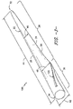
- FIG. 1 illustrates a wind turbine 10 according to conventional construction.
- the wind turbine 10 includes a tower 12 with a nacelle 14 mounted thereon.
- a plurality of rotor blades 16 are mounted to a rotor hub 18, which is in turn connected to a main flange that turns a main rotor shaft.
- the wind turbine power generation and control components are housed within the nacelle 14.
- the view of FIG. 1 is provided for illustrative purposes only to place the present invention in an exemplary field of use. It should be appreciated that the invention is not limited to any particular type of wind turbine configuration.
- the present invention is not limited to use with wind turbines, but may be utilized in any application having rotor blades.
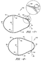
- FIG. 2 illustrates a cross-section of a flatback airfoil 19 according to conventional construction.
- the flatback airfoil 19 includes a leading edge 20 and a flat trailing edge 20 and is typically utilized in the inboard region of a rotor blade to allow for higher lift of thick airfoils at reduced chords.
- traditional flatback designs as shown in FIG. 2 can be extremely costly and complicated to manufacture.
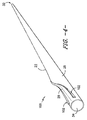
- a rotor blade assembly 100 includes a rotor blade 22 having exterior surfaces defining a pressure side 23, a suction side 24, a leading edge 26, and a trailing edge 28.
- the pressure and suction sides 23, 24 may each extend between the leading edge 26 and the trailing edge 28.
- the exterior surfaces extend between an inboard region 36 and an outboard region 38 in a generally span-wise direction.
- the inboard region 36 includes the blade root 34 and the outboard region 38 includes the blade tip 32.
- the pressure and suction sides 23, 24, as well as the leading and trailing edges 26, 28, are generally aerodynamic surfaces having aerodynamic contours, as is generally known in the art. More specifically, as shown in FIGS. 6-12 , portions of the trailing edge 28, e.g. in the inboard region 36, have been shortened and rounded to form a rotor blade 22 having a smaller cross-sectional area with a rounded or roundback configuration.
- the rotor blade 22 may further define a chord 42 and a span 44 extending in chord-wise and span-wise directions, respectively. Further, as shown, the chord 42 may vary throughout the span 44 of the rotor blade 22. Thus, as discussed below, a local chord 46 may be defined for the rotor blade 22 at any point on the rotor blade 22 along the span 44. Further, the rotor blade 22 may define a maximum chord 48, as shown.
- FIGS. 5-11 illustrate a shear web 62 extending between two spar caps 64.
- the shear web 62 and spar caps 64 may extend through the rotor blade 22 or any portion thereof in the generally span-wise direction.
- the external surfaces defining the pressure side 23 and suction side 24 may include, or may cover, the spar caps 64.
- the rotor blade assembly 100 includes at least one airflow separation element 102.
- the airflow separation element(s) 102 is configured to provide a fixed airflow separation location in the inboard region 36 during standard operation.
- the airflow separation element(s) 102 may be located from about 90% chord to about 95% chord from the leading edge 26 of the rotor blade 22.
- the airflow separation element(s) 102 may extend through any suitable span-wise portion of the rotor blade 22, and may thus have any suitable length relative to the span 44.
- the airflow separation element(s) 102 may extend from the root 34 towards the tip 32 as shown in FIG. 3 .
- the airflow separation element(s) 102 may augment the lift capacity, reduce the drag, and/or augment the lift to drag ratio of the rotor blade 22 during standard operation.
- the airflow separation element(s) 102 may include any suitable elements configured to separate airflow from a surface of the blade 22.
- the airflow separation element(s) 102 may include one or more airflow separation anchors 104, one or more airflow separation plates 106, or a non-structural fairing 110.
- the airflow separation element(s) 102 correspond to one or more flow separation anchors 104.
- the rotor blade 22 includes opposing flow separation anchors 104 on each of the pressure and suction sides 23, 24. FIG.
- FIG. 5 illustrates opposing airflow separation anchors 104 mounted to a truncated rotor blade 22, whereas FIG. 6 illustrates opposing airflow separation anchors 104 mounted to a standard rotor blade 22.
- the flow separation anchors 104 are typically designed to include an aerodynamic contour that matches the aerodynamic surface of the pressure and suction sides 23, 24.
- the outer surfaces of the flow separation anchors 104 may define a generally continuous aerodynamic surface with an exterior surface, such as the pressure side 23 or suction side 24, of the rotor blade 22.
- a generally continuous aerodynamic surface is a surface that has a generally continuous aerodynamic contour. Thus, when two surfaces define a generally continuous aerodynamic surface, there is relatively little interruption in the aerodynamic contour at the intersection of the two surfaces.
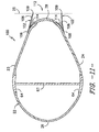
- the airflow separation anchors 104 generally include a proximal end 105 and a distal end 107, with the proximal and distal ends 105, 107 being mounted to either or both of the pressure or suction sides 23, 24 of the rotor blade 22.
- the rounded trailing edge 28 is configured to extend beyond the airflow separation anchor(s) 104 in a generally chord-wise direction.
- the distal ends 107 or edges of the airflow separation anchors 104 define an airflow separation line 25. As such, since the distal ends 107 of the airflow separation anchors 104 align along the airflow separation line, the airfoil mimic a flatback airfoil during operation.
- the airflow separation anchors 104 typically include a wedge-shaped cross-section having a substantially flat distal end 107. As such, when mounted to the rotor blade 22, the airflow separation anchors 104 are configured to mimic a flatback airfoil.
- the airflow separation element(s) 102 may also include one or more airflow separation plates 106. More specifically, as shown in FIG. 7 (inset), the airflow separation plate(s) 106 may include a proximal end 108 and a distal end 109. The proximal end 108 may be the end that is mounted to either or both of the pressure or suction sides 23, 24 of the rotor blade 22, whereas the distal end 109 may be the end that is not mounted to the rotor blade 22.
- the proximal end 108 of the airflow separation plate 106 is mounted to the pressure side 23 of the rotor blade 22, whereas the distal end 109 extends from the pressure side 23 of the rotor blade 22.
- the rotor blade 22 includes opposing airflow separation plates 106 with the proximal ends 108 mounted to the pressure and suction sides 23, 24 of the rotor blade 22, respectively.
- the proximal ends 108 may be mounted through the use of, for example, a suitable adhesive or a suitable brazing or welding technique, or may be mounted through the use of, for example, suitable mechanical fasteners such as screws, nails, rivets, nut-bolt combinations, etc.
- the distal end(s) 109 of the airflow separation plates 106 when the proximal end(s) 108 of the airflow separation plate(s) 106 is mounted to the rotor blade 22, the distal end(s) 109 substantially aligns with or is shorter than the rounded trailing edge 28 of the rotor blade 22 in a generally chord-wise direction. Accordingly, the distal ends 109 of the airflow separation plates 106 define a fixed airflow separation line 25.
- the distal ends 109 of the airflow separation plates 106 may extend beyond the rounded trailing edge 28 of the rotor blade 22 in a generally chord-wise direction when the proximal end(s) 108 of the airflow separation plate(s) 106 is mounted to the rotor blade 22. Accordingly, the airflow separation plates 106 extend to a flow separation line 25 beyond the rounded trailing edge 28 in a chord-wise direction. In such an embodiment, the distal ends 109 of the opposing airflow separation plates 106 create a void 112 therebetween.
- the rotor blade assembly 100 may also include at least one structural component 114 configured between the airflow separation plate(s) 106 and the corresponding surface 23, 24 of the rotor blade 22.
- the structural component 114 may be, for example, rods, wedges, or webs, or any other suitable components that provide structural support.
- the structural component 114 may include a wedge configured between the airflow separation plate(s) 106 and either the pressure or suction sides 23, 24 of the rotor blade 22.
- the structural component(s) 114 may extend at any suitable direction and at any suitable location between the airflow separation plate(s) 106 and either the pressure or suction sides 23, 24 of the rotor blade 22.
- a single structural component(s) 114 may extend along a suitable portion of the span 44 of the rotor blade 22, and/or a plurality of structural component(s) 114 may be disposed and spaced apart along the span 44 of the rotor blade 22 or any portion thereof.
- the structural component(s) 114 is configured to provide support to the airflow separation plate(s) 106 when mounted to the rotor blade 22 so as to maintain the airflow separation plate(s) 106 at a desired location.
- the airflow separation element(s) 102 may include a non-structural fairing 110 configured with the rounded trailing edge 28 of the rotor blade 22.
- the non-structural fairing 110 typically includes a straight portion 116 configured between a first end 117 and a second end 118.
- the straight portion 116 creates a flatback trailing edge of the rotor blade 22 that aligns with flow separation line 25, as shown in FIG. 10 .
- the fairing 110 provides a flow separation line 25 that extends beyond the rounded trailing edge 28 in a chord-wise direction.
- Each airflow separation element(s) 102 may be formed from any suitable materials.
- the material utilized to form the airflow separation element(s) 102 may preferably be lightweight, and may further preferably be suitably rigid to maintain its structure during use in a wind turbine 10. More specifically, the airflow separation element(s) 102 may be formed from fiberglass, aluminum, or any other suitable material.
Applications Claiming Priority (1)
| Application Number | Priority Date | Filing Date | Title |
|---|---|---|---|
| US14/690,726 US10180125B2 (en) | 2015-04-20 | 2015-04-20 | Airflow configuration for a wind turbine rotor blade |
Publications (2)
| Publication Number | Publication Date |
|---|---|
| EP3085952A1 true EP3085952A1 (fr) | 2016-10-26 |
| EP3085952B1 EP3085952B1 (fr) | 2020-01-01 |
Family
ID=55754195
Family Applications (1)
| Application Number | Title | Priority Date | Filing Date |
|---|---|---|---|
| EP16165310.0A Active EP3085952B1 (fr) | 2015-04-20 | 2016-04-14 | Configuration d'écoulement d'air pour une pale de rotor de turbine éolienne |
Country Status (6)
| Country | Link |
|---|---|
| US (1) | US10180125B2 (fr) |
| EP (1) | EP3085952B1 (fr) |
| CN (1) | CN106065845B (fr) |
| BR (1) | BR102016007993B1 (fr) |
| DK (1) | DK3085952T3 (fr) |
| ES (1) | ES2782799T3 (fr) |
Cited By (2)
| Publication number | Priority date | Publication date | Assignee | Title |
|---|---|---|---|---|
| WO2020038916A1 (fr) | 2018-08-21 | 2020-02-27 | Wobben Properties Gmbh | Pale de rotor d'éolienne |
| WO2021028461A1 (fr) * | 2019-08-14 | 2021-02-18 | Lm Wind Power A/S | Ensemble pale d'éolienne et procédé de production d'une pale d'éolienne |
Families Citing this family (14)
| Publication number | Priority date | Publication date | Assignee | Title |
|---|---|---|---|---|
| CN103974878B (zh) * | 2011-07-22 | 2019-07-30 | Lm Wp 专利控股有限公司 | 用于翼型的涡流发生器装置 |
| ES2855987T3 (es) * | 2015-09-03 | 2021-09-27 | Siemens Gamesa Renewable Energy As | Pala de turbina eólica con pestaña de borde de salida |
| DE102016201114A1 (de) * | 2016-01-26 | 2017-07-27 | Wobben Properties Gmbh | Rotorblatt einer Windenergieanlage und Windenergieanlage |
| KR101731951B1 (ko) * | 2016-06-21 | 2017-05-11 | 한국항공대학교산학협력단 | 풍력 발전기용 블레이드 |
| CN107061142A (zh) * | 2017-01-25 | 2017-08-18 | 北京博比风电科技有限公司 | 叶片和风力发电机组 |
| CN106545465A (zh) * | 2017-01-25 | 2017-03-29 | 北京博比风电科技有限公司 | 延迟分离尾缘叶片 |
| US20190024631A1 (en) * | 2017-07-20 | 2019-01-24 | General Electric Company | Airflow configuration for a wind turbine rotor blade |
| US10821696B2 (en) * | 2018-03-26 | 2020-11-03 | General Electric Company | Methods for manufacturing flatback airfoils for wind turbine rotor blades |
| EP3587798B1 (fr) * | 2018-06-27 | 2020-10-14 | Siemens Gamesa Renewable Energy A/S | Structure aérodynamique |
| EP3587799A1 (fr) | 2018-06-27 | 2020-01-01 | Siemens Gamesa Renewable Energy A/S | Structure aérodynamique |
| CN111379662A (zh) * | 2018-12-29 | 2020-07-07 | 中材科技风电叶片股份有限公司 | 风电叶片及风机 |
| CN111379661A (zh) * | 2018-12-29 | 2020-07-07 | 中材科技风电叶片股份有限公司 | 风电叶片、风机及风电叶片制造方法 |
| GB201905845D0 (en) * | 2019-04-26 | 2019-06-12 | Blade Dynamics Ltd | Method for producting a wind turbine blade and wind turbine blade |
| DE102019113080A1 (de) * | 2019-05-17 | 2020-11-19 | Wobben Properties Gmbh | Rotorblatt und Windenergieanlage |
Citations (6)
| Publication number | Priority date | Publication date | Assignee | Title |
|---|---|---|---|---|
| US20090274559A1 (en) * | 2006-04-13 | 2009-11-05 | Repower Systems Ag | Rotor blade of a wind energy unit |
| EP2141358A1 (fr) * | 2008-12-12 | 2010-01-06 | Lm Glasfiber A/S | Pale d'éolienne dotée d'un déflecteur avec une séparation efficace de la circulation de l'air |
| EP2343451A1 (fr) * | 2009-10-08 | 2011-07-13 | Lm Glasfiber A/S | Pale d'éolienne avec une pluralité de dispositifs de guidage d'écoulement |
| US20120027588A1 (en) * | 2011-05-20 | 2012-02-02 | General Electric Company | Root flap for rotor blade in wind turbine |
| EP2514961A1 (fr) * | 2011-04-19 | 2012-10-24 | Siemens Aktiengesellschaft | Déflecteur pour pale de rotor d'éolienne |
| WO2014025252A1 (fr) * | 2012-08-06 | 2014-02-13 | Stichting Energieonderzoek Centrum Nederland | Profil à queue d'hirondelle |
Family Cites Families (103)
| Publication number | Priority date | Publication date | Assignee | Title |
|---|---|---|---|---|
| USRE19412E (en) | 1935-01-01 | Aircraft and control thereof | ||
| US573562A (en) | 1896-12-22 | Propeller | ||
| US175355A (en) | 1876-03-28 | Waltee king | ||
| US2899128A (en) | 1959-08-11 | Vaghi | ||
| US1861065A (en) | 1930-08-18 | 1932-05-31 | Poot Philippe | Screw-propeller for flying machines and other aerodynamics apparatus |
| US2071012A (en) | 1932-11-22 | 1937-02-16 | Adams Herbert Luther | Noiseless device |
| US2126813A (en) | 1936-03-09 | 1938-08-16 | Mildred M Reid | Variable pitch propeller |
| US2238749A (en) | 1939-01-30 | 1941-04-15 | Clarence B Swift | Fan blade |
| US2225312A (en) | 1939-10-05 | 1940-12-17 | Bell Telephone Labor Inc | Acoustic device |
| US2312219A (en) | 1941-04-21 | 1943-02-23 | Sensenich Brothers | Aircraft propeller |
| US2469167A (en) | 1946-06-11 | 1949-05-03 | American Steel & Wire Co | Vibration damper |
| JPS5115210A (en) | 1974-07-02 | 1976-02-06 | Rotoron Inc | Zatsuongenshono fuan |
| US4204629A (en) | 1977-07-20 | 1980-05-27 | Rolls-Royce Limited | Brush seal and a method of manufacture |
| US4618313A (en) | 1980-02-06 | 1986-10-21 | Cofimco S.R.L. | Axial propeller with increased effective displacement of air whose blades are not twisted |
| GB8626408D0 (en) | 1986-11-05 | 1987-12-16 | Secr Defence | Damping treatment for pipes & bodies |
| US4720244A (en) | 1987-05-21 | 1988-01-19 | Hudson Products Corporation | Fan blade for an axial flow fan and method of forming same |
| US5088665A (en) | 1989-10-31 | 1992-02-18 | The United States Of America As Represented By The Administrator Of The National Aeronautics And Space Administration | Serrated trailing edges for improving lift and drag characteristics of lifting surfaces |
| US5320491A (en) | 1992-07-09 | 1994-06-14 | Northern Power Systems, Inc. | Wind turbine rotor aileron |
| EP0615903B1 (fr) | 1993-03-13 | 1999-09-15 | GKN Westland Helicopters Limited | Pales tournantes |
| US5328329A (en) | 1993-07-06 | 1994-07-12 | Hudson Products Corporation | Fan blade width extender |
| NL9301910A (nl) | 1993-11-04 | 1995-06-01 | Stork Prod Eng | Windturbine. |
| US5522266A (en) | 1993-11-30 | 1996-06-04 | Medex, Inc. | Low cost pressure transducer particularly for medical applications |
| CA2141529A1 (fr) | 1994-10-25 | 1996-04-26 | Frances Gould | Brosse pour balai mecanique |
| US6352601B1 (en) | 1994-12-27 | 2002-03-05 | The B. F. Goodrich Company | Self-adhering ice protector |
| DE19647102A1 (de) | 1996-11-14 | 1998-05-20 | Philippe Arribi | Strömungskörper |
| JP2000120524A (ja) | 1998-10-16 | 2000-04-25 | Mitsubishi Heavy Ind Ltd | 風車翼 |
| BR9916091A (pt) | 1998-12-09 | 2001-09-04 | Aloys Wobben | Lâmina de rotor para instalação de energia eólica, e, instalação de energia eólica |
| GB2358130A (en) | 2000-01-17 | 2001-07-18 | Llewellyn Jones John Adrian | One-piece toothbrush |
| DE10020177A1 (de) | 2000-04-25 | 2001-11-08 | Daimler Chrysler Ag | Einrichtung zur Lärmminderung an Tragflügeln von Flugzeugen |
| BR0003706A (pt) | 2000-05-30 | 2002-02-13 | Tecsis Tecnologia E Sist S Ava | Pá para ventilador axial de baixo ruìdo e alta eficiência |
| DK174318B1 (da) | 2000-06-19 | 2002-12-02 | Lm Glasfiber As | Vindmølle til stall-reguleret vindmølle og som omfatter et eller flere organer i form af flapper eller slatter, der er fastgjort til vingen til ændring af dennes profil afhængig af luftens temperatur |
| NL1015558C2 (nl) * | 2000-06-28 | 2002-01-08 | Stichting En Onderzoek Ct Nede | Blad van een windturbine. |
| US6733240B2 (en) | 2001-07-18 | 2004-05-11 | General Electric Company | Serrated fan blade |
| CN1294353C (zh) | 2001-07-19 | 2007-01-10 | Neg麦康公司 | 风力涡轮机叶片及其制造方法 |
| DE10157849A1 (de) | 2001-11-24 | 2003-06-12 | Airbus Gmbh | Anordnung zur Minderung des aerodynamischen Lärms an einem Vorflügel eines Verkehrsflugzeuges |
| US6872048B2 (en) | 2001-11-26 | 2005-03-29 | Lennox Industries, Inc. | Fan with reduced noise generation |
| US7059833B2 (en) | 2001-11-26 | 2006-06-13 | Bonus Energy A/S | Method for improvement of the efficiency of a wind turbine rotor |
| EP1338793A3 (fr) | 2002-02-22 | 2010-09-01 | Mitsubishi Heavy Industries, Ltd. | Bord de fuite cranelée pour pale d'éolienne |
| JP2003254225A (ja) | 2002-03-05 | 2003-09-10 | Ebara Corp | 風車の気流騒音低減装置 |
| CN100455793C (zh) | 2003-03-31 | 2009-01-28 | 丹麦技术大学 | 风轮机叶片、风轮机以及控制风轮机工作条件的方法 |
| DE102004008618A1 (de) | 2004-02-21 | 2005-09-08 | Geka Brush Gmbh | Pinsel zum Auftragen kosmetischer oder pflegender Mittel |
| ES2627790T3 (es) * | 2005-05-17 | 2017-07-31 | Vestas Wind Systems A/S | Pala de turbina eólica controlada por cabeceo que tiene medios de generación de turbulencia, turbina eólica y uso de la misma |
| US7328770B2 (en) | 2005-06-16 | 2008-02-12 | Owens Jeffrey A | Strap silencer |
| US7637721B2 (en) | 2005-07-29 | 2009-12-29 | General Electric Company | Methods and apparatus for producing wind energy with reduced wind turbine noise |
| AU2006299847A1 (en) | 2005-08-22 | 2007-04-19 | Viryd Technologies Inc. | Fluid energy converter |
| ES2318925B1 (es) | 2005-09-22 | 2010-02-11 | GAMESA INNOVATION & TECHNOLOGY, S.L. | Aerogenerador con un rotor de palas que reduce el ruido. |
| US7458777B2 (en) | 2005-09-22 | 2008-12-02 | General Electric Company | Wind turbine rotor assembly and blade having acoustic flap |
| US7604461B2 (en) * | 2005-11-17 | 2009-10-20 | General Electric Company | Rotor blade for a wind turbine having aerodynamic feature elements |
| DK176352B1 (da) | 2005-12-20 | 2007-09-10 | Lm Glasfiber As | Profilserie til vinge til vindenergianlæg |
| NL1031223C1 (nl) | 2006-02-23 | 2007-08-24 | Stichting Nationaal Lucht En R | Reductie van windturbinegeluid door borstels op de achterrand van de bladen. |
| ES2855106T3 (es) * | 2006-04-02 | 2021-09-23 | Wobben Properties Gmbh | Aerogenerador con pala delgada |
| US7740206B2 (en) | 2006-04-13 | 2010-06-22 | The Board Of Trustees Of The Leland Stanford Junior University | Translating active Gurney flap to alleviate aircraft wake vortex hazard |
| BE1017134A5 (nl) | 2006-05-11 | 2008-03-04 | Delaere Marc | Borstel voor een schrob-,veeg- en/of boenmachine en sproei-inrichting voor het reinigen van meerdere door middel van groeven en/of voegen van elkaar gescheiden oppervlakten. |
| US20080001363A1 (en) | 2006-06-28 | 2008-01-03 | General Electric Company | Brush sealing system and method for rotary machines |
| EP1892442A1 (fr) | 2006-08-18 | 2008-02-27 | Siemens Aktiengesellschaft | Joint à brosse pour turbomachine |
| US10611468B2 (en) | 2006-09-08 | 2020-04-07 | Steven Sullivan | Method and apparatus for mitigating trailing vortex wakes of lifting or thrust generating bodies |
| DE102006043462A1 (de) | 2006-09-15 | 2008-03-27 | Deutsches Zentrum für Luft- und Raumfahrt e.V. | Aerodynamisches Bauteil mit einer gewellten Hinterkante |
| US7959412B2 (en) | 2006-09-29 | 2011-06-14 | General Electric Company | Wind turbine rotor blade with acoustic lining |
| US7811063B2 (en) | 2006-11-03 | 2010-10-12 | General Electric Company | Damping element for a wind turbine rotor blade |
| EP1927454A1 (fr) | 2006-11-29 | 2008-06-04 | Trisa Holding AG | Brosse à dents avec surface partiellement revêtue |
| US20080166241A1 (en) | 2007-01-04 | 2008-07-10 | Stefan Herr | Wind turbine blade brush |
| US8226368B2 (en) | 2007-01-09 | 2012-07-24 | General Electric Company | Wind turbine airfoil family |
| US7883324B2 (en) | 2007-01-09 | 2011-02-08 | General Electric Company | Wind turbine airfoil family |
| US7918653B2 (en) | 2007-02-07 | 2011-04-05 | General Electric Company | Rotor blade trailing edge assemby and method of use |
| US7413408B1 (en) | 2007-02-22 | 2008-08-19 | Samuel B Tafoya | Vibration-reducing and noise-reducing spoiler for helicopter rotors, aircraft wings, propellers, and turbine blades |
| WO2008113349A2 (fr) | 2007-03-20 | 2008-09-25 | Vestas Wind Systems A/S | Éolienne à rotation lente dotée de pales plus effilées |
| US7828523B2 (en) | 2007-03-27 | 2010-11-09 | General Electric Company | Rotor blade for a wind turbine having a variable dimension |
| WO2008131800A1 (fr) | 2007-04-30 | 2008-11-06 | Vestas Wind Systems A/S | Pale d'éolienne |
| ES2345583B1 (es) | 2007-05-31 | 2011-07-28 | GAMESA INNOVATION & TECHNOLOGY, S.L. | Pala de aerogenerador con dispositivos anti-ruido. |
| US7927078B2 (en) | 2007-07-12 | 2011-04-19 | General Electric Company | Wind turbine blade tip vortex breakers |
| NL2000821C2 (nl) | 2007-08-17 | 2009-02-18 | Stichting Energie | Windturbine en rotorblad. |
| US20090074585A1 (en) | 2007-09-19 | 2009-03-19 | General Electric Company | Wind turbine blades with trailing edge serrations |
| US20090097976A1 (en) | 2007-10-15 | 2009-04-16 | General Electric Company | Active damping of wind turbine blades |
| DK2053240T3 (da) | 2007-10-22 | 2011-07-11 | Actiflow B V | Vindturbine med grænselagskontrol |
| US8418967B2 (en) | 2008-02-21 | 2013-04-16 | Cornerstone Research Group, Inc. | Passive adaptive structures |
| ES2343397B1 (es) * | 2008-03-07 | 2011-06-13 | GAMESA INNOVATION & TECHNOLOGY, S.L. | Una pala de aerogenerador. |
| EP2107235A1 (fr) | 2008-04-02 | 2009-10-07 | Lm Glasfiber A/S | Pale d'éolienne dotée d'une surface portante auxiliaire |
| US8192161B2 (en) | 2008-05-16 | 2012-06-05 | Frontier Wind, Llc. | Wind turbine with deployable air deflectors |
| GB2462308A (en) | 2008-08-01 | 2010-02-03 | Vestas Wind Sys As | Extension portion for wind turbine blade |
| CN102007291A (zh) | 2008-08-06 | 2011-04-06 | 三菱重工业株式会社 | 风车翼和使用该风车翼的风力发电装置 |
| US9239039B2 (en) | 2008-10-27 | 2016-01-19 | General Electric Company | Active circulation control of aerodynamic structures |
| EP2138714A1 (fr) | 2008-12-12 | 2009-12-30 | Lm Glasfiber A/S | Pale d'éolienne dotée d'un dispositif de guidage d'écoulement de hauteur optimisée |
| US20100143151A1 (en) | 2009-02-06 | 2010-06-10 | General Electric Company | Permeable acoustic flap for wind turbine blades |
| EP2253838A1 (fr) | 2009-05-18 | 2010-11-24 | Lm Glasfiber A/S | Procédé de fonctionnement d'une éolienne |
| WO2010141720A2 (fr) | 2009-06-03 | 2010-12-09 | Flodesign Wind Turbine Corp. | Pales d'éoliennes à lobes de mélange |
| EP2270312A1 (fr) | 2009-07-01 | 2011-01-05 | PEM-Energy Oy | Construction aréo- ou hydrodynamique |
| DK2343450T3 (en) * | 2009-10-08 | 2019-04-15 | Lm Wind Power As | Wind turbine blade with longitudinal flow guiding device having a plate-shaped element. |
| EP2360374B1 (fr) | 2009-10-08 | 2019-05-08 | LM Wind Power A/S | Pale d'éolienne avec un dispositif de guidage d'écoulement orienté vers l'avant |
| US8011887B2 (en) | 2010-07-21 | 2011-09-06 | General Electric Company | Rotor blade assembly |
| US8083488B2 (en) | 2010-08-23 | 2011-12-27 | General Electric Company | Blade extension for rotor blade in wind turbine |
| US7976276B2 (en) | 2010-11-04 | 2011-07-12 | General Electric Company | Noise reducer for rotor blade in wind turbine |
| US7976283B2 (en) | 2010-11-10 | 2011-07-12 | General Electric Company | Noise reducer for rotor blade in wind turbine |
| US8523515B2 (en) | 2010-11-15 | 2013-09-03 | General Electric Company | Noise reducer for rotor blade in wind turbine |
| US8267657B2 (en) | 2010-12-16 | 2012-09-18 | General Electric Company | Noise reducer for rotor blade in wind turbine |
| US8414261B2 (en) | 2011-05-31 | 2013-04-09 | General Electric Company | Noise reducer for rotor blade in wind turbine |
| US8834127B2 (en) | 2011-09-09 | 2014-09-16 | General Electric Company | Extension for rotor blade in wind turbine |
| JP5297558B1 (ja) | 2011-10-12 | 2013-09-25 | 三菱重工業株式会社 | 風車翼及びこれを備えた風力発電装置ならびに風車翼の設計方法 |
| US8376703B2 (en) | 2011-11-21 | 2013-02-19 | General Electric Company | Blade extension for rotor blade in wind turbine |
| US8430633B2 (en) * | 2011-11-21 | 2013-04-30 | General Electric Company | Blade extension for rotor blade in wind turbine |
| PL2877737T3 (pl) * | 2012-07-25 | 2016-12-30 | Łopata turbiny wiatrowej mająca grzebień aerodynamiczny lub element zmieniający kierunek przepływu | |
| US20140093380A1 (en) * | 2012-10-03 | 2014-04-03 | General Electric Company | Noise reduction tab and method for wind turbine rotor blade |
| US9556849B2 (en) * | 2013-05-02 | 2017-01-31 | General Electric Company | Attachment system and method for wind turbine vortex generators |
| US9494132B2 (en) * | 2013-05-07 | 2016-11-15 | General Electric Company | Airflow modifying assembly for a rotor blade of a wind turbine |
-
2015
- 2015-04-20 US US14/690,726 patent/US10180125B2/en active Active
-
2016
- 2016-04-11 BR BR102016007993-4A patent/BR102016007993B1/pt active IP Right Grant
- 2016-04-14 DK DK16165310.0T patent/DK3085952T3/da active
- 2016-04-14 ES ES16165310T patent/ES2782799T3/es active Active
- 2016-04-14 EP EP16165310.0A patent/EP3085952B1/fr active Active
- 2016-04-20 CN CN201610245942.5A patent/CN106065845B/zh active Active
Patent Citations (6)
| Publication number | Priority date | Publication date | Assignee | Title |
|---|---|---|---|---|
| US20090274559A1 (en) * | 2006-04-13 | 2009-11-05 | Repower Systems Ag | Rotor blade of a wind energy unit |
| EP2141358A1 (fr) * | 2008-12-12 | 2010-01-06 | Lm Glasfiber A/S | Pale d'éolienne dotée d'un déflecteur avec une séparation efficace de la circulation de l'air |
| EP2343451A1 (fr) * | 2009-10-08 | 2011-07-13 | Lm Glasfiber A/S | Pale d'éolienne avec une pluralité de dispositifs de guidage d'écoulement |
| EP2514961A1 (fr) * | 2011-04-19 | 2012-10-24 | Siemens Aktiengesellschaft | Déflecteur pour pale de rotor d'éolienne |
| US20120027588A1 (en) * | 2011-05-20 | 2012-02-02 | General Electric Company | Root flap for rotor blade in wind turbine |
| WO2014025252A1 (fr) * | 2012-08-06 | 2014-02-13 | Stichting Energieonderzoek Centrum Nederland | Profil à queue d'hirondelle |
Cited By (4)
| Publication number | Priority date | Publication date | Assignee | Title |
|---|---|---|---|---|
| WO2020038916A1 (fr) | 2018-08-21 | 2020-02-27 | Wobben Properties Gmbh | Pale de rotor d'éolienne |
| DE102018120264A1 (de) * | 2018-08-21 | 2020-02-27 | Wobben Properties Gmbh | Windenergieanlagen-Rotorblatt |
| WO2021028461A1 (fr) * | 2019-08-14 | 2021-02-18 | Lm Wind Power A/S | Ensemble pale d'éolienne et procédé de production d'une pale d'éolienne |
| US11927171B2 (en) | 2019-08-14 | 2024-03-12 | Lm Wind Power A/S | Wind turbine blade assembly and method for producing a wind turbine blade |
Also Published As
| Publication number | Publication date |
|---|---|
| CN106065845A (zh) | 2016-11-02 |
| BR102016007993A2 (pt) | 2016-11-16 |
| ES2782799T3 (es) | 2020-09-16 |
| CN106065845B (zh) | 2020-10-27 |
| US20160305398A1 (en) | 2016-10-20 |
| US10180125B2 (en) | 2019-01-15 |
| EP3085952B1 (fr) | 2020-01-01 |
| DK3085952T3 (da) | 2020-04-06 |
| BR102016007993B1 (pt) | 2023-01-31 |
Similar Documents
| Publication | Publication Date | Title |
|---|---|---|
| EP3085952B1 (fr) | Configuration d'écoulement d'air pour une pale de rotor de turbine éolienne | |
| EP2868916B1 (fr) | Rallonges de corde destinées à un ensemble de pale de rotor d'éolienne | |
| US9523279B2 (en) | Rotor blade fence for a wind turbine | |
| DK178555B1 (en) | Wind turbine rotor blade | |
| US9377005B2 (en) | Airfoil modifiers for wind turbine rotor blades | |
| US8262362B2 (en) | Wind turbine blade shear web with spring flanges | |
| US20110142636A1 (en) | Expansion assembly for a rotor blade of a wind turbine | |
| US20090140527A1 (en) | Wind turbine blade stiffeners | |
| DK178725B1 (en) | Rear binder cap for wind turbine rotor blades | |
| US20120027588A1 (en) | Root flap for rotor blade in wind turbine | |
| US8360732B2 (en) | Rotor blade section and method for assembling a rotor blade for a wind turbine | |
| US8622707B2 (en) | Root attachment for a rotor blade assembly | |
| DK201270441A (en) | Wind turbine blade multi-component shear web with intermediate connection assembly | |
| US9494134B2 (en) | Noise reducing extension plate for rotor blade in wind turbine | |
| DK201200554A (en) | Extension for rotor blade in wind turbine | |
| EP2728169A2 (fr) | Éléments structurels pour pale de rotor d'éolienne | |
| EP3655645B1 (fr) | Configuration d'écoulement d'air pour une pale de rotor de turbine éolienne | |
| CN113167212A (zh) | 经由其叶片尖端节段中的增加的预弯曲具有最大化的总体预弯曲的分段式转子叶片 | |
| US20130064677A1 (en) | Rotor blade assembly for wind turbine | |
| JP2005147080A (ja) | 水平軸風車のブレード | |
| EP2851557A1 (fr) | Pale d'eolienne avec des volets aérodynamiques placés au pied de la pale |
Legal Events
| Date | Code | Title | Description |
|---|---|---|---|
| PUAI | Public reference made under article 153(3) epc to a published international application that has entered the european phase |
Free format text: ORIGINAL CODE: 0009012 |
|
| AK | Designated contracting states |
Kind code of ref document: A1 Designated state(s): AL AT BE BG CH CY CZ DE DK EE ES FI FR GB GR HR HU IE IS IT LI LT LU LV MC MK MT NL NO PL PT RO RS SE SI SK SM TR |
|
| AX | Request for extension of the european patent |
Extension state: BA ME |
|
| STAA | Information on the status of an ep patent application or granted ep patent |
Free format text: STATUS: EXAMINATION IS IN PROGRESS |
|
| 17P | Request for examination filed |
Effective date: 20170426 |
|
| RBV | Designated contracting states (corrected) |
Designated state(s): AL AT BE BG CH CY CZ DE DK EE ES FI FR GB GR HR HU IE IS IT LI LT LU LV MC MK MT NL NO PL PT RO RS SE SI SK SM TR |
|
| 17Q | First examination report despatched |
Effective date: 20170526 |
|
| 17Q | First examination report despatched |
Effective date: 20170612 |
|
| GRAP | Despatch of communication of intention to grant a patent |
Free format text: ORIGINAL CODE: EPIDOSNIGR1 |
|
| STAA | Information on the status of an ep patent application or granted ep patent |
Free format text: STATUS: GRANT OF PATENT IS INTENDED |
|
| INTG | Intention to grant announced |
Effective date: 20190702 |
|
| GRAS | Grant fee paid |
Free format text: ORIGINAL CODE: EPIDOSNIGR3 |
|
| GRAJ | Information related to disapproval of communication of intention to grant by the applicant or resumption of examination proceedings by the epo deleted |
Free format text: ORIGINAL CODE: EPIDOSDIGR1 |
|
| GRAL | Information related to payment of fee for publishing/printing deleted |
Free format text: ORIGINAL CODE: EPIDOSDIGR3 |
|
| STAA | Information on the status of an ep patent application or granted ep patent |
Free format text: STATUS: EXAMINATION IS IN PROGRESS |
|
| GRAR | Information related to intention to grant a patent recorded |
Free format text: ORIGINAL CODE: EPIDOSNIGR71 |
|
| STAA | Information on the status of an ep patent application or granted ep patent |
Free format text: STATUS: GRANT OF PATENT IS INTENDED |
|
| GRAA | (expected) grant |
Free format text: ORIGINAL CODE: 0009210 |
|
| STAA | Information on the status of an ep patent application or granted ep patent |
Free format text: STATUS: THE PATENT HAS BEEN GRANTED |
|
| INTC | Intention to grant announced (deleted) | ||
| INTG | Intention to grant announced |
Effective date: 20191120 |
|
| AK | Designated contracting states |
Kind code of ref document: B1 Designated state(s): AL AT BE BG CH CY CZ DE DK EE ES FI FR GB GR HR HU IE IS IT LI LT LU LV MC MK MT NL NO PL PT RO RS SE SI SK SM TR |
|
| REG | Reference to a national code |
Ref country code: GB Ref legal event code: FG4D |
|
| REG | Reference to a national code |
Ref country code: CH Ref legal event code: EP Ref country code: AT Ref legal event code: REF Ref document number: 1220077 Country of ref document: AT Kind code of ref document: T Effective date: 20200115 |
|
| REG | Reference to a national code |
Ref country code: IE Ref legal event code: FG4D |
|
| REG | Reference to a national code |
Ref country code: DE Ref legal event code: R096 Ref document number: 602016027143 Country of ref document: DE |
|
| REG | Reference to a national code |
Ref country code: DK Ref legal event code: T3 Effective date: 20200331 |
|
| REG | Reference to a national code |
Ref country code: NL Ref legal event code: MP Effective date: 20200101 |
|
| REG | Reference to a national code |
Ref country code: LT Ref legal event code: MG4D |
|
| PG25 | Lapsed in a contracting state [announced via postgrant information from national office to epo] |
Ref country code: FI Free format text: LAPSE BECAUSE OF FAILURE TO SUBMIT A TRANSLATION OF THE DESCRIPTION OR TO PAY THE FEE WITHIN THE PRESCRIBED TIME-LIMIT Effective date: 20200101 Ref country code: LT Free format text: LAPSE BECAUSE OF FAILURE TO SUBMIT A TRANSLATION OF THE DESCRIPTION OR TO PAY THE FEE WITHIN THE PRESCRIBED TIME-LIMIT Effective date: 20200101 Ref country code: RS Free format text: LAPSE BECAUSE OF FAILURE TO SUBMIT A TRANSLATION OF THE DESCRIPTION OR TO PAY THE FEE WITHIN THE PRESCRIBED TIME-LIMIT Effective date: 20200101 Ref country code: PT Free format text: LAPSE BECAUSE OF FAILURE TO SUBMIT A TRANSLATION OF THE DESCRIPTION OR TO PAY THE FEE WITHIN THE PRESCRIBED TIME-LIMIT Effective date: 20200527 Ref country code: CZ Free format text: LAPSE BECAUSE OF FAILURE TO SUBMIT A TRANSLATION OF THE DESCRIPTION OR TO PAY THE FEE WITHIN THE PRESCRIBED TIME-LIMIT Effective date: 20200101 Ref country code: NL Free format text: LAPSE BECAUSE OF FAILURE TO SUBMIT A TRANSLATION OF THE DESCRIPTION OR TO PAY THE FEE WITHIN THE PRESCRIBED TIME-LIMIT Effective date: 20200101 Ref country code: NO Free format text: LAPSE BECAUSE OF FAILURE TO SUBMIT A TRANSLATION OF THE DESCRIPTION OR TO PAY THE FEE WITHIN THE PRESCRIBED TIME-LIMIT Effective date: 20200401 |
|
| PG25 | Lapsed in a contracting state [announced via postgrant information from national office to epo] |
Ref country code: HR Free format text: LAPSE BECAUSE OF FAILURE TO SUBMIT A TRANSLATION OF THE DESCRIPTION OR TO PAY THE FEE WITHIN THE PRESCRIBED TIME-LIMIT Effective date: 20200101 Ref country code: BG Free format text: LAPSE BECAUSE OF FAILURE TO SUBMIT A TRANSLATION OF THE DESCRIPTION OR TO PAY THE FEE WITHIN THE PRESCRIBED TIME-LIMIT Effective date: 20200401 Ref country code: GR Free format text: LAPSE BECAUSE OF FAILURE TO SUBMIT A TRANSLATION OF THE DESCRIPTION OR TO PAY THE FEE WITHIN THE PRESCRIBED TIME-LIMIT Effective date: 20200402 Ref country code: IS Free format text: LAPSE BECAUSE OF FAILURE TO SUBMIT A TRANSLATION OF THE DESCRIPTION OR TO PAY THE FEE WITHIN THE PRESCRIBED TIME-LIMIT Effective date: 20200501 Ref country code: SE Free format text: LAPSE BECAUSE OF FAILURE TO SUBMIT A TRANSLATION OF THE DESCRIPTION OR TO PAY THE FEE WITHIN THE PRESCRIBED TIME-LIMIT Effective date: 20200101 Ref country code: LV Free format text: LAPSE BECAUSE OF FAILURE TO SUBMIT A TRANSLATION OF THE DESCRIPTION OR TO PAY THE FEE WITHIN THE PRESCRIBED TIME-LIMIT Effective date: 20200101 |
|
| REG | Reference to a national code |
Ref country code: ES Ref legal event code: FG2A Ref document number: 2782799 Country of ref document: ES Kind code of ref document: T3 Effective date: 20200916 |
|
| REG | Reference to a national code |
Ref country code: DE Ref legal event code: R026 Ref document number: 602016027143 Country of ref document: DE |
|
| PLBI | Opposition filed |
Free format text: ORIGINAL CODE: 0009260 |
|
| PLAX | Notice of opposition and request to file observation + time limit sent |
Free format text: ORIGINAL CODE: EPIDOSNOBS2 |
|
| PG25 | Lapsed in a contracting state [announced via postgrant information from national office to epo] |
Ref country code: RO Free format text: LAPSE BECAUSE OF FAILURE TO SUBMIT A TRANSLATION OF THE DESCRIPTION OR TO PAY THE FEE WITHIN THE PRESCRIBED TIME-LIMIT Effective date: 20200101 Ref country code: SK Free format text: LAPSE BECAUSE OF FAILURE TO SUBMIT A TRANSLATION OF THE DESCRIPTION OR TO PAY THE FEE WITHIN THE PRESCRIBED TIME-LIMIT Effective date: 20200101 Ref country code: SM Free format text: LAPSE BECAUSE OF FAILURE TO SUBMIT A TRANSLATION OF THE DESCRIPTION OR TO PAY THE FEE WITHIN THE PRESCRIBED TIME-LIMIT Effective date: 20200101 Ref country code: EE Free format text: LAPSE BECAUSE OF FAILURE TO SUBMIT A TRANSLATION OF THE DESCRIPTION OR TO PAY THE FEE WITHIN THE PRESCRIBED TIME-LIMIT Effective date: 20200101 |
|
| 26 | Opposition filed |
Opponent name: SIEMENS GAMESA RENEWABLE ENERGY GMBH & CO. KG Effective date: 20200928 |
|
| REG | Reference to a national code |
Ref country code: AT Ref legal event code: MK05 Ref document number: 1220077 Country of ref document: AT Kind code of ref document: T Effective date: 20200101 |
|
| PG25 | Lapsed in a contracting state [announced via postgrant information from national office to epo] |
Ref country code: MC Free format text: LAPSE BECAUSE OF FAILURE TO SUBMIT A TRANSLATION OF THE DESCRIPTION OR TO PAY THE FEE WITHIN THE PRESCRIBED TIME-LIMIT Effective date: 20200101 |
|
| REG | Reference to a national code |
Ref country code: CH Ref legal event code: PL |
|
| PG25 | Lapsed in a contracting state [announced via postgrant information from national office to epo] |
Ref country code: AT Free format text: LAPSE BECAUSE OF FAILURE TO SUBMIT A TRANSLATION OF THE DESCRIPTION OR TO PAY THE FEE WITHIN THE PRESCRIBED TIME-LIMIT Effective date: 20200101 Ref country code: IT Free format text: LAPSE BECAUSE OF FAILURE TO SUBMIT A TRANSLATION OF THE DESCRIPTION OR TO PAY THE FEE WITHIN THE PRESCRIBED TIME-LIMIT Effective date: 20200101 Ref country code: CH Free format text: LAPSE BECAUSE OF NON-PAYMENT OF DUE FEES Effective date: 20200430 Ref country code: LU Free format text: LAPSE BECAUSE OF NON-PAYMENT OF DUE FEES Effective date: 20200414 Ref country code: LI Free format text: LAPSE BECAUSE OF NON-PAYMENT OF DUE FEES Effective date: 20200430 |
|
| REG | Reference to a national code |
Ref country code: BE Ref legal event code: MM Effective date: 20200430 |
|
| PLBB | Reply of patent proprietor to notice(s) of opposition received |
Free format text: ORIGINAL CODE: EPIDOSNOBS3 |
|
| PG25 | Lapsed in a contracting state [announced via postgrant information from national office to epo] |
Ref country code: PL Free format text: LAPSE BECAUSE OF FAILURE TO SUBMIT A TRANSLATION OF THE DESCRIPTION OR TO PAY THE FEE WITHIN THE PRESCRIBED TIME-LIMIT Effective date: 20200101 Ref country code: SI Free format text: LAPSE BECAUSE OF FAILURE TO SUBMIT A TRANSLATION OF THE DESCRIPTION OR TO PAY THE FEE WITHIN THE PRESCRIBED TIME-LIMIT Effective date: 20200101 Ref country code: BE Free format text: LAPSE BECAUSE OF NON-PAYMENT OF DUE FEES Effective date: 20200430 |
|
| PG25 | Lapsed in a contracting state [announced via postgrant information from national office to epo] |
Ref country code: IE Free format text: LAPSE BECAUSE OF NON-PAYMENT OF DUE FEES Effective date: 20200414 |
|
| PG25 | Lapsed in a contracting state [announced via postgrant information from national office to epo] |
Ref country code: TR Free format text: LAPSE BECAUSE OF FAILURE TO SUBMIT A TRANSLATION OF THE DESCRIPTION OR TO PAY THE FEE WITHIN THE PRESCRIBED TIME-LIMIT Effective date: 20200101 Ref country code: MT Free format text: LAPSE BECAUSE OF FAILURE TO SUBMIT A TRANSLATION OF THE DESCRIPTION OR TO PAY THE FEE WITHIN THE PRESCRIBED TIME-LIMIT Effective date: 20200101 Ref country code: CY Free format text: LAPSE BECAUSE OF FAILURE TO SUBMIT A TRANSLATION OF THE DESCRIPTION OR TO PAY THE FEE WITHIN THE PRESCRIBED TIME-LIMIT Effective date: 20200101 |
|
| RDAE | Information deleted related to despatch of communication that patent is revoked |
Free format text: ORIGINAL CODE: EPIDOSDREV1 |
|
| RDAF | Communication despatched that patent is revoked |
Free format text: ORIGINAL CODE: EPIDOSNREV1 |
|
| PLCK | Communication despatched that opposition was rejected |
Free format text: ORIGINAL CODE: EPIDOSNREJ1 |
|
| PG25 | Lapsed in a contracting state [announced via postgrant information from national office to epo] |
Ref country code: MK Free format text: LAPSE BECAUSE OF FAILURE TO SUBMIT A TRANSLATION OF THE DESCRIPTION OR TO PAY THE FEE WITHIN THE PRESCRIBED TIME-LIMIT Effective date: 20200101 Ref country code: AL Free format text: LAPSE BECAUSE OF FAILURE TO SUBMIT A TRANSLATION OF THE DESCRIPTION OR TO PAY THE FEE WITHIN THE PRESCRIBED TIME-LIMIT Effective date: 20200101 |
|
| APBM | Appeal reference recorded |
Free format text: ORIGINAL CODE: EPIDOSNREFNO |
|
| APBP | Date of receipt of notice of appeal recorded |
Free format text: ORIGINAL CODE: EPIDOSNNOA2O |
|
| APAH | Appeal reference modified |
Free format text: ORIGINAL CODE: EPIDOSCREFNO |
|
| PLAB | Opposition data, opponent's data or that of the opponent's representative modified |
Free format text: ORIGINAL CODE: 0009299OPPO |
|
| R26 | Opposition filed (corrected) |
Opponent name: SIEMENS GAMESA RENEWABLE ENERGY GMBH & CO. KG Effective date: 20200928 |
|
| APBQ | Date of receipt of statement of grounds of appeal recorded |
Free format text: ORIGINAL CODE: EPIDOSNNOA3O |
|
| PGFP | Annual fee paid to national office [announced via postgrant information from national office to epo] |
Ref country code: FR Payment date: 20230321 Year of fee payment: 8 Ref country code: DK Payment date: 20230321 Year of fee payment: 8 |
|
| PGFP | Annual fee paid to national office [announced via postgrant information from national office to epo] |
Ref country code: GB Payment date: 20230321 Year of fee payment: 8 |
|
| P01 | Opt-out of the competence of the unified patent court (upc) registered |
Effective date: 20230522 |
|
| PGFP | Annual fee paid to national office [announced via postgrant information from national office to epo] |
Ref country code: ES Payment date: 20230502 Year of fee payment: 8 Ref country code: DE Payment date: 20230321 Year of fee payment: 8 |
|
| REG | Reference to a national code |
Ref country code: GB Ref legal event code: 732E Free format text: REGISTERED BETWEEN 20231123 AND 20231129 |
|
| REG | Reference to a national code |
Ref country code: DE Ref legal event code: R082 Ref document number: 602016027143 Country of ref document: DE Representative=s name: ZIMMERMANN & PARTNER PATENTANWAELTE MBB, DE Ref country code: DE Ref legal event code: R082 Ref document number: 602016027143 Country of ref document: DE Ref country code: DE Ref legal event code: R081 Ref document number: 602016027143 Country of ref document: DE Owner name: LM WIND POWER A/S, DK Free format text: FORMER OWNER: GENERAL ELECTRIC COMPANY, SCHENECTADY, NY, US |
|
| REG | Reference to a national code |
Ref country code: DE Ref legal event code: R082 Ref document number: 602016027143 Country of ref document: DE Representative=s name: ZIMMERMANN & PARTNER PATENTANWAELTE MBB, DE |