EP2927482A1 - A wind turbine blade provided with an erosion shield - Google Patents
A wind turbine blade provided with an erosion shield Download PDFInfo
- Publication number
- EP2927482A1 EP2927482A1 EP14163048.3A EP14163048A EP2927482A1 EP 2927482 A1 EP2927482 A1 EP 2927482A1 EP 14163048 A EP14163048 A EP 14163048A EP 2927482 A1 EP2927482 A1 EP 2927482A1
- Authority
- EP
- European Patent Office
- Prior art keywords
- blade
- wind turbine
- erosion shield
- turbine blade
- shell body
- Prior art date
- Legal status (The legal status is an assumption and is not a legal conclusion. Google has not performed a legal analysis and makes no representation as to the accuracy of the status listed.)
- Withdrawn
Links
- 230000003628 erosive effect Effects 0.000 title claims abstract description 96
- 239000010410 layer Substances 0.000 claims abstract description 71
- 239000011159 matrix material Substances 0.000 claims abstract description 35
- 229920003235 aromatic polyamide Polymers 0.000 claims abstract description 21
- 230000002787 reinforcement Effects 0.000 claims abstract description 16
- 239000011247 coating layer Substances 0.000 claims abstract description 14
- 239000002131 composite material Substances 0.000 claims abstract description 14
- 239000000835 fiber Substances 0.000 claims abstract description 12
- 239000004760 aramid Substances 0.000 claims abstract description 9
- 229920002635 polyurethane Polymers 0.000 claims description 21
- 239000004814 polyurethane Substances 0.000 claims description 21
- OKTJSMMVPCPJKN-UHFFFAOYSA-N Carbon Chemical compound [C] OKTJSMMVPCPJKN-UHFFFAOYSA-N 0.000 claims description 11
- 229910052799 carbon Inorganic materials 0.000 claims description 11
- 229920000642 polymer Polymers 0.000 claims description 10
- 238000004519 manufacturing process Methods 0.000 claims description 9
- 238000000034 method Methods 0.000 claims description 9
- 239000003365 glass fiber Substances 0.000 claims description 7
- 239000004593 Epoxy Substances 0.000 claims description 6
- 229920000728 polyester Polymers 0.000 claims description 6
- 238000003475 lamination Methods 0.000 claims description 5
- 238000009420 retrofitting Methods 0.000 claims description 5
- 229920001567 vinyl ester resin Polymers 0.000 claims description 5
- 239000011521 glass Substances 0.000 claims description 3
- 239000000463 material Substances 0.000 description 31
- 239000002245 particle Substances 0.000 description 7
- 230000035939 shock Effects 0.000 description 7
- 230000007704 transition Effects 0.000 description 7
- XLYOFNOQVPJJNP-UHFFFAOYSA-N water Substances O XLYOFNOQVPJJNP-UHFFFAOYSA-N 0.000 description 5
- 230000008439 repair process Effects 0.000 description 4
- 239000011248 coating agent Substances 0.000 description 3
- 238000000576 coating method Methods 0.000 description 3
- 238000005336 cracking Methods 0.000 description 3
- 239000000428 dust Substances 0.000 description 3
- 230000000694 effects Effects 0.000 description 3
- 229920005989 resin Polymers 0.000 description 3
- 239000011347 resin Substances 0.000 description 3
- 229920002430 Fibre-reinforced plastic Polymers 0.000 description 2
- 125000001931 aliphatic group Chemical group 0.000 description 2
- 125000003118 aryl group Chemical group 0.000 description 2
- 230000007613 environmental effect Effects 0.000 description 2
- 239000011151 fibre-reinforced plastic Substances 0.000 description 2
- 230000009477 glass transition Effects 0.000 description 2
- 239000012948 isocyanate Substances 0.000 description 2
- 238000000465 moulding Methods 0.000 description 2
- 239000000565 sealant Substances 0.000 description 2
- LFQSCWFLJHTTHZ-UHFFFAOYSA-N Ethanol Chemical compound CCO LFQSCWFLJHTTHZ-UHFFFAOYSA-N 0.000 description 1
- 238000010521 absorption reaction Methods 0.000 description 1
- 239000002390 adhesive tape Substances 0.000 description 1
- 238000004458 analytical method Methods 0.000 description 1
- -1 aromatic isocyanate Chemical class 0.000 description 1
- 239000007795 chemical reaction product Substances 0.000 description 1
- 238000010276 construction Methods 0.000 description 1
- 230000007423 decrease Effects 0.000 description 1
- 230000001419 dependent effect Effects 0.000 description 1
- 238000000113 differential scanning calorimetry Methods 0.000 description 1
- 125000002887 hydroxy group Chemical group [H]O* 0.000 description 1
- 230000003116 impacting effect Effects 0.000 description 1
- 150000002513 isocyanates Chemical class 0.000 description 1
- 238000003754 machining Methods 0.000 description 1
- 239000000203 mixture Substances 0.000 description 1
- 238000012805 post-processing Methods 0.000 description 1
- 239000011253 protective coating Substances 0.000 description 1
- 230000003014 reinforcing effect Effects 0.000 description 1
- 239000007787 solid Substances 0.000 description 1
- 239000007921 spray Substances 0.000 description 1
Images

Classifications
-
- F—MECHANICAL ENGINEERING; LIGHTING; HEATING; WEAPONS; BLASTING
- F03—MACHINES OR ENGINES FOR LIQUIDS; WIND, SPRING, OR WEIGHT MOTORS; PRODUCING MECHANICAL POWER OR A REACTIVE PROPULSIVE THRUST, NOT OTHERWISE PROVIDED FOR
- F03D—WIND MOTORS
- F03D1/00—Wind motors with rotation axis substantially parallel to the air flow entering the rotor
- F03D1/06—Rotors
- F03D1/065—Rotors characterised by their construction elements
- F03D1/0675—Rotors characterised by their construction elements of the blades
-
- B—PERFORMING OPERATIONS; TRANSPORTING
- B29—WORKING OF PLASTICS; WORKING OF SUBSTANCES IN A PLASTIC STATE IN GENERAL
- B29L—INDEXING SCHEME ASSOCIATED WITH SUBCLASS B29C, RELATING TO PARTICULAR ARTICLES
- B29L2031/00—Other particular articles
- B29L2031/08—Blades for rotors, stators, fans, turbines or the like, e.g. screw propellers
- B29L2031/082—Blades, e.g. for helicopters
- B29L2031/085—Wind turbine blades
-
- F—MECHANICAL ENGINEERING; LIGHTING; HEATING; WEAPONS; BLASTING
- F05—INDEXING SCHEMES RELATING TO ENGINES OR PUMPS IN VARIOUS SUBCLASSES OF CLASSES F01-F04
- F05B—INDEXING SCHEME RELATING TO WIND, SPRING, WEIGHT, INERTIA OR LIKE MOTORS, TO MACHINES OR ENGINES FOR LIQUIDS COVERED BY SUBCLASSES F03B, F03D AND F03G
- F05B2230/00—Manufacture
- F05B2230/90—Coating; Surface treatment
-
- F—MECHANICAL ENGINEERING; LIGHTING; HEATING; WEAPONS; BLASTING
- F05—INDEXING SCHEMES RELATING TO ENGINES OR PUMPS IN VARIOUS SUBCLASSES OF CLASSES F01-F04
- F05B—INDEXING SCHEME RELATING TO WIND, SPRING, WEIGHT, INERTIA OR LIKE MOTORS, TO MACHINES OR ENGINES FOR LIQUIDS COVERED BY SUBCLASSES F03B, F03D AND F03G
- F05B2280/00—Materials; Properties thereof
- F05B2280/60—Properties or characteristics given to material by treatment or manufacturing
- F05B2280/6003—Composites; e.g. fibre-reinforced
-
- Y—GENERAL TAGGING OF NEW TECHNOLOGICAL DEVELOPMENTS; GENERAL TAGGING OF CROSS-SECTIONAL TECHNOLOGIES SPANNING OVER SEVERAL SECTIONS OF THE IPC; TECHNICAL SUBJECTS COVERED BY FORMER USPC CROSS-REFERENCE ART COLLECTIONS [XRACs] AND DIGESTS
- Y02—TECHNOLOGIES OR APPLICATIONS FOR MITIGATION OR ADAPTATION AGAINST CLIMATE CHANGE
- Y02E—REDUCTION OF GREENHOUSE GAS [GHG] EMISSIONS, RELATED TO ENERGY GENERATION, TRANSMISSION OR DISTRIBUTION
- Y02E10/00—Energy generation through renewable energy sources
- Y02E10/70—Wind energy
- Y02E10/72—Wind turbines with rotation axis in wind direction
-
- Y—GENERAL TAGGING OF NEW TECHNOLOGICAL DEVELOPMENTS; GENERAL TAGGING OF CROSS-SECTIONAL TECHNOLOGIES SPANNING OVER SEVERAL SECTIONS OF THE IPC; TECHNICAL SUBJECTS COVERED BY FORMER USPC CROSS-REFERENCE ART COLLECTIONS [XRACs] AND DIGESTS
- Y02—TECHNOLOGIES OR APPLICATIONS FOR MITIGATION OR ADAPTATION AGAINST CLIMATE CHANGE
- Y02P—CLIMATE CHANGE MITIGATION TECHNOLOGIES IN THE PRODUCTION OR PROCESSING OF GOODS
- Y02P70/00—Climate change mitigation technologies in the production process for final industrial or consumer products
- Y02P70/50—Manufacturing or production processes characterised by the final manufactured product
Definitions
- the present invention relates to a wind turbine blade provided with an erosion shield, a method of manufacturing a blade provided with an erosion shield, and a method of retrofitting an erosion shield to the surface of a wind turbine blade.
- Wind turbine blades are often made of a composite material reinforced with glass fibres, carbon fibres or a combination of glass and carbon fibres embedded in a polymer matrix, typically polyester, vinylester or epoxy.
- Aramid fibres have been suggested as fibre-reinforcement material, but compared to glass fibres and carbon fibres, aramid fibres have a poorer adhesion to resin, are more expensive, have a lower fibre strength, have a lower stiffness (than carbon fibres), have poorer compressive strength and are not suitable for post processing operations, such as machining or grinding. Therefore, aramid fibres have not commercially found use as reinforcement fibres in wind turbine blades.
- wind turbine blades Due to their operation in various locations, and across a wide variety of environmental conditions, wind turbine blades can experience cracking or failure of the blade surface due to continued impact of particles including rain, hail, dust, etc., on the blades, in particular on the leading edge of the blades. Erosion can also have a negative impact on the aerodynamics of a wind turbine blade, resulting in an associated loss in wind turbine power production. Such continued erosion and cracking or failure requires relatively complicated service operations to repair, and in some cases replace, the affected blades. These service operations can increase the operating cost of the wind turbines in question considerably.
- wind turbine blades are sometimes provided with erosion protection systems to prevent such cracking or failure.
- This may be in the form of a leading edge protective coating or tape provided on the blade surface, the coating or tape formed from a material adapted to present improved resistance to environmental erosion compared to the relatively hard and brittle material normally used in the construction of the wind turbine components, e.g. fibre-based composite material used in the manufacture of a wind turbine blade body, and/or an epoxy or polyester-based gelcoat used to coat such a wind turbine blade body.
- An example of a known erosion shield for a wind turbine blade can be seen in EP 2153065 .
- the invention provides a wind turbine blade having a blade shell body made of a composite material comprising reinforcement fibres of a first fibre type embedded in a matrix material of a first matrix type, wherein the blade comprises a tip end and a root end as well as a leading edge and a trailing edge, wherein the blade comprises an erosion shield extending along an exterior surface of at least a portion of the blade shell body, wherein the erosion shield comprises:
- the invention provides a wind turbine blade made from a conventional composite structure comprising e.g. glass fibres or carbon fibres embedded in a polymer matrix of polyester, vinylester or epoxy, and which an erosion shield reinforced with aramid fibres, which has a higher impact strength than that of glass fibres and carbon fibres, protects.
- the blade is protected by a strong erosion shield, which may prolong the lifetime of the wind turbine blade or at least prolong the periods between services or repairs of the blade.
- the erosion shield is protected with a UV resistant coating layer which ensures that the strength of the aramid fibres is maintained under operation, and which may further extend the periods between services or repairs of the blade.
- the erosion shield may be provided as a relative thin layer on the exterior surface of the blade and along only a limited erosion critical part of the blade, whereby the additional cost of utilising aramid fibres may be minimised.
- the second matrix type is a polyurethane polymer, e.g. an aliphatic or aromatic polyurethane, preferably an aromatic polyurethane.
- the polyurethane polymer may for instance comprise an aliphatic or aromatic isocyanate. This type of polymer provides a sufficient resin adhesion to the aramid fibres and may further provide a sufficient bond to the polymer matrix of the wind turbine blade.
- the polyurethane polymer may be designed to a desired hardness.
- the at least one inner layer of the erosion shield may for instance be designed so as to absorb impact forces from particles on the erosion shield, and so as to reduce the possibility of interfacial failure between the erosion shield and wind turbine blade body.
- the particles may be any elements or detritus which may impact on a surface of the wind turbine blade during operation, e.g. water droplets in the form of rain or sea spray, dust particles, hail, etc.
- the wind turbine blade body is substantially formed from a fibre-reinforced plastics composite material.
- the cushioning material is selected to provide secure adhesion towards the wind turbine blade body and to the outer layer of erosion-resistant material.
- said inner layer is formed from a material having a Shore A hardness of between 25-90, preferably between 50-90.
- the erosion shield further comprises a primer layer between the at least one inner layer and the at least one outer layer.
- This intermediate layer provides an improved adhesion between the at least one inner layer and the at least one outer layer.
- the UV resistant coating layer could for instance be W4600, which is available from 3M.
- the primer layer may be coloured in a different colour from the remainder of the erosion shield and the blade, which may help in identifying a starting erosion.
- the primer layer may for instance be coloured blue.
- the polyurethane material has a glass transition temperature Tg below a predefined operational temperature range of the wind turbine blade.
- Tg is below +5 degrees Celsius.
- Providing a polyurethane material having a Tg below the predicted operational temperature of the wind turbine blade means that the polyurethane material will be maintained in an amorphous, molten rubber-like state during turbine operation, and will provide the necessary cushioning effect, while ensuring secure adhesion with the external erosion shield layer and the underlying blade body.
- the Tg can be selected at this relatively low level, in contrast to the relatively high Tg required for wind turbine blade structural features, e.g. the Germanischer Lloyd requirement for a Tg onset of greater than 65 degrees Celsius for structural materials, i.e. the first inclination on a differential scanning calorimetry (DSC) curve used to analyse polymer composition.
- DSC differential scanning calorimetry
- the Tg of the inner layer is between -20 degrees to +10 degrees Celsius, preferably between approximately -5 to +3 degrees Celsius.
- the inner layer will be substantially formed from a relatively molten, rubber-like material, which will act to efficiently absorb any impact shock waves in the erosion shield before reaching the body of the wind turbine.
- the inner layer is selected such that the cushioning material is flexible to absorb the impact shock waves received from water at approximately 4 degrees Celsius, i.e. when the density of water is at a maximum, whereas the aramid reinforcement fibres provide the improved erosion resistance of the layer.
- Tg is between approximately -5 to -2 degrees Celsius.
- the impacting particles will generally have reduced force, e.g. water will fall as snow.
- the inner layer will generally not be required to absorb as much impact energy.
- the erosion shield is arranged along at least a section of the leading edge of the blade. Thereby, the leading edge of the blade, which is particular prone to erosion, is further protected.
- the erosion shield may for instance extend across a bond interface between a pressure side shell part and a suction side shell part of the blade shell.
- the erosion shield extends along a longitudinal part of the blade, the longitudinal part extending along 1-50% of the length of the blade, advantageously extending along 1-35% of the blade.
- the erosion shield extends only along a limited part of the blade, preferably along the leading edge of the blade.
- the longitudinal extent of said longitudinal part may even be only a few meters of the blade, e.g. 1-10 meters or 1-5 meters of the blade.
- the longitudinal part is arranged on an outer part of the blade near the tip.
- the erosion shield is provided as an over-lamination.
- This over-lamination may be carried out during manufacture of the wind turbine blade, or it may be carried out as a post-operation.
- the erosion shield may be applied as a pre-manufactured element, as a tape, or as a prepreg material, which may be applied to the outer surface of the blade.
- Such embodiments are particularly suitable for retrofitting of blades already installed on wind turbines.
- the first fibre type is preferably chosen from the group of glass fibres, carbon fibres, or a combination of glass and carbon fibres.
- the first matrix type is preferably chosen from the group of polyester, vinylester, or an epoxy.
- the at least inner layer has a thickness of 0.5-5 mm, more preferably 1-3 mm.
- the at least outer layer has a thickness of 0.1-2 mm, more preferably 0.3-1 mm.
- the invention provides a method of manufacturing a wind turbine blade, wherein the method comprises the steps of:
- the wind turbine blade is manufactured according to a method known per se and that the erosion shield is applied to the exterior of the blade shell body so as to provide an improved erosion resistance to a part of the blade.
- the erosion shield is applied along the leading edge of the blade and along an outer part of the blade.
- the erosion shield may be provided via an over-lamination.
- the erosion shield is provided as part of a prepreg or an adhesive tape to be applied to a wind turbine blade, wherein said layer of aramid reinforced polymer is provided as an inner layer with an outer layer made of an UV resistant coating.
- the invention provides a method of retrofitting an erosion shield to a surface of a wind turbine blade having a blade shell body made of a composite material comprising reinforcement fibres of a first fibre type embedded in a matrix material of a first matrix type, wherein the blade comprises a tip end and a root end as well as a leading edge and a trailing edge, wherein the method comprises the steps of:
- the manufacturing method or retrofitting method may comprise the step of providing a recessed channel on a portion of the surface of the wind turbine blade shell body, wherein said recessed channel is arranged to receive said at least one layer of cushioning material.
- a recessed channel ensures that the aerodynamics of the finished blade will not be significantly affected by the use of the multi-layered erosion shield. It will be understood that said recessed channel may be formed during moulding of a wind turbine blade shell, or such a channel may be cut into or ground from the surface of a standard wind turbine blade shell.
- the thickness of the layer may also be tapered towards the sides of the erosion shield, such that a gradual transition is achieved between the blade shell body and the erosion shield.
- an aerodynamic smooth surface may be achieved without forming a recess in the blade shell.
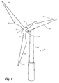
- Fig. 1 illustrates a conventional modern upwind wind turbine according to the so-called "Danish concept" with a tower 4, a nacelle 6 and a rotor with a substantially horizontal rotor shaft.
- the rotor includes a hub 8 and three blades 10 extending radially from the hub 8, each having a blade root 16 nearest the hub and a blade tip 14 farthest from the hub 8.
- the rotor has a radius denoted R.
- Fig. 2 shows a schematic view of a first embodiment of a wind turbine blade 10 according to the invention.
- the wind turbine blade 10 has the shape of a conventional wind turbine blade and comprises a root region 30 closest to the hub, a profiled or an airfoil region 34 farthest away from the hub and a transition region 32 between the root region 30 and the airfoil region 34.
- the blade 10 comprises a leading edge 18 facing the direction of rotation of the blade 10, when the blade is mounted on the hub, and a trailing edge 20 facing the opposite direction of the leading edge 18.
- the airfoil region 34 (also called the profiled region) has an ideal or almost ideal blade shape with respect to generating lift, whereas the root region 30 due to structural considerations has a substantially circular or elliptical cross-section, which for instance makes it easier and safer to mount the blade 10 to the hub.
- the diameter (or the chord) of the root region 30 may be constant along the entire root area 30.
- the transition region 32 has a transitional profile gradually changing from the circular or elliptical shape of the root region 30 to the airfoil profile of the airfoil region 34.
- the chord length of the transition region 32 typically increases with increasing distance r from the hub.
- the airfoil region 34 has an airfoil profile with a chord extending between the leading edge 18 and the trailing edge 20 of the blade 10. The width of the chord decreases with increasing distance r from the hub.
- a shoulder 40 of the blade 10 is defined as the position, where the blade 10 has its largest chord length.
- the shoulder 40 is typically provided at the boundary between the transition region 32 and the airfoil region 34.
- chords of different sections of the blade normally do not lie in a common plane, since the blade may be twisted and/or curved (i.e. pre-bent), thus providing the chord plane with a correspondingly twisted and/or curved course, this being most often the case in order to compensate for the local velocity of the blade being dependent on the radius from the hub.
- the blade is typically made from a pressure side shell part 36 and a suction side shell part 38 that are glued to each other along bond lines at the leading edge 18 and the trailing edge of the blade 20.
- the blade is provided with an erosion shield 70, which is arranged at the leading edge 18 of the blade 10 and extends along a longitudinal part of the blade having a length L e .
- the erosion shield 70 may advantageously be arranged along e.g. the outer half or outer third of the blade only near the blade tip 14, i.e. L e / L ⁇ 0.5 or L e / L ⁇ 0.33.
- the erosion shield may even extend along a few metres only of the blade, e.g. 1-10 metres or 1-5 metres, for instance approximately 3 metres. Taking into account that wind turbine blades manufactured today typically are between 40 and 80 metres, this means that the ratio between L e and L may even be 1-25%, or 1-20%, or 1-15%, or even 1-10%.
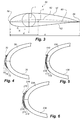
- Fig. 3 shows a schematic view of an airfoil profile 50 of a typical blade of a wind turbine depicted with the various parameters which are typically used to define the geometrical shape of an airfoil.
- the airfoil profile 50 has a pressure side 52 and a suction side 54, which during use - i.e. during rotation of the rotor - normally face towards the windward (or upwind) side and the leeward (or downwind) side, respectively.
- the airfoil 50 has a chord 60 with a chord length c extending between a leading edge 56 and a trailing edge 58 of the blade.
- the airfoil 50 has a thickness t, which is defined as the distance between the pressure side 52 and the suction side 54.
- the thickness t of the airfoil varies along the chord 60.
- the deviation from a symmetrical profile is given by a camber line 62, which is a median line through the airfoil profile 50.
- the median line can be found by drawing inscribed circles from the leading edge 56 to the trailing edge 58.
- the median line follows the centres of these inscribed circles and the deviation or distance from the chord 60 is called the camber f.
- the asymmetry can also be defined by use of parameters called the upper camber and lower camber, which are defined as the distances from the chord 60 and the suction side 54 and pressure side 52, respectively.
- Airfoil profiles are often characterised by the following parameters: the chord length c, the maximum camber f, the position df of the maximum camber f, the maximum airfoil thickness t, which is the largest diameter of the inscribed circles along the median camber line 62, the position dt of the maximum thickness t, and a nose radius (not shown). These parameters are typically defined as ratios to the chord length c.
- Wind turbine blades are generally formed from fibre-reinforced plastics material, i.e. glass fibres and/or carbon fibres which are arranged in a mould and cured with a resin, typically polyester, vinylester or epoxy, to form a solid structure.
- Erosion shields in the form of a layer of erosion-resistant material are sometimes provided on wind turbine blades, usually at the leading edge 56, in order to prevent damage to the fibre-based composite material from the erosive qualities of rain, hail, dust particles, etc. continually striking the wind turbine blade surface during the lifetime of the blade.
- Figs. 4-6 show various embodiments of blades with erosion shields according to the invention.
- the erosion shield is arranged to be provided on the leading edge of a wind turbine blade across the bond line between the pressure side shell part and the suction side shell part.
- the erosion shield according to the invention in general comprises an inner layer made of a polyurethane material reinforced with aramid fibres, an outer layer made of a UV resistant coating layer, and an intermediate primer layer.
- Fig. 4 shows a first embodiment of an erosion shield 70 according to the invention.
- the erosion shield is arranged across the bond line of a pressure side shell part 36 and a suction side shell part 38 and comprises an inner layer 72 made of a polyurethane material reinforced with aramid fibres, an outer layer 76 made of a UV resistant coating layer, and an intermediate primer layer 74.
- the thickness of the erosion shield 70 is tapered towards the sides of the erosion shield 70, such that a gradual transition is achieved between the blade shell body and the erosion shield 70.
- Fig. 5 shows a second embodiment of an erosion shield 170 according to the invention.
- the erosion shield is arranged across the bond line of a pressure side shell part 136 and a suction side shell part 138 and comprises an inner layer 172 made of a polyurethane material reinforced with aramid fibres, an outer layer 176 made of a UV resistant coating layer, and an intermediate primer layer 174.
- a recessed channel is formed on a portion of the surface of the wind turbine blade shell body, and the erosion shield 170 is arranged in the recessed channel.
- a channel ensures that the aerodynamics of the finished blade will not be significantly affected by the use of the multi-layered erosion shield, since the outer surface of the erosion shield may be substantially flush with the outer surface of the blade shell body.
- said recessed channel may be formed during moulding of a wind turbine blade shell, or such a channel may be cut into or ground from the surface of a standard wind turbine blade shell.
- Fig. 6 shows a third embodiment of an erosion shield 270 according to the invention.
- the erosion shield is arranged across the bond line of a pressure side shell part 236 and a suction side shell part 238 and comprises an inner layer 272 made of a polyurethane material reinforced with aramid fibres, an outer layer 276 made of a UV resistant coating layer, and an intermediate primer layer 274.
- the thicknesses of the three layers 272, 274, 276 are substantially uniform.
- a sealant 278 is arranged at the sides of the erosion shield in order to provide a smooth aerodynamic surface and to improve the adhesion the outer surface of the blade.
- the sealant 278 may be separately provided, or it may for instance be part of the UV resistant coating layer.
- the erosion shields of Figs. 4-6 may be applied to the surface of the wind turbine blade during manufacturing of the wind turbine blade, or it may be retrofitted to the surface of an existing blade.
- the erosion shield may be applied as an over-lamination or alternatively as a pre-manufactured element or a tape.
- the polyurethane material may be adapted to provide a cushioning effect for any impact shock waves which propagate through the erosion shield after the erosion shield is struck by a particle. Accordingly, this cushioning effect acts to absorb the energy from any such shock waves and to substantially dissipate the energy before said shock wave reaches the interface between erosion shield and the surface of the wind turbine blade. Further, by reinforcing the polyurethane material with aramid fibres, it is ensured that the layer is highly erosion resistant, which in turn means that the periods between service of the wind turbine blade may be extended, which again means that production down time may be minimised. Further, polyurethane has the advantage of being relatively cheap and of providing a good adhesion to the surface of the composite material of the blade shell body.
- the polyurethane material may be formed from the reaction product of an alcohol/hydroxyl-group and isocyanate.
- the polyurethane material may advantageously have a Shore A hardness rating of between 25-90, preferably between 50-90.
- the polyurethane material has a glass transition temperature Tg which is below a portion of the specified operational temperature range of the wind turbine blade.
- Tg glass transition temperature
- the inner layer material will be provided in an amorphous rubber-like state for at least a section of the wind turbine blade operational range. This results in increased flexibility of the inner layer, with a corresponding increase in the ability of the inner layer to absorb impact shock waves.
- the material of the inner layer may be selected such that Tg is between +20 to +10 degrees Celsius. Preferably, Tg is below +5 degrees Celsius, as this will ensure that the inner layer is in this relatively flexible state for a temperature of +4 degrees, i.e. when water density level is at a maximum. While wind industry standards require that composite materials have relatively high Tg levels, e.g. the Germanischer Lloyd requirement for a Tg onset of greater than 65 degrees Celsius for structural materials, the inner layer of the erosion shield of the invention is not a load bearing component, and is not subject to such requirements.
- the depth of the inner layer may be selected based on the level of absorption of shockwave forces desired to achieve, and/or on the predicted operating conditions of the wind turbine blade.
- the inner layer has a thickness of 0.5-5 mm, more preferably 1-3 mm.
- the at least outer layer has a thickness of 0.1-2 mm, more preferably 0.3-1 mm.
- the erosion shield may comprise a plurality of inner layers of erosion-resistant material, e.g. with polyurethane material having different shore A hardness, and/or a plurality of layers of UV resistant coating.
Abstract
A wind turbine blade having a blade shell body made of a composite material comprising reinforcement fibres of a first fibre type embedded in a matrix material of a first matrix type is described. The blade comprises a tip end and a root end as well as a leading edge and a trailing edge. The blade comprises an erosion shield extending along an exterior surface of at least a portion of the blade shell body. The erosion shield comprises at least one inner layer of aramid reinforcement fibres embedded in a matrix material of a second matrix type, and at least one outer layer made of an UV resistant coating layer.
Description
- The present invention relates to a wind turbine blade provided with an erosion shield, a method of manufacturing a blade provided with an erosion shield, and a method of retrofitting an erosion shield to the surface of a wind turbine blade.
- Wind turbine blades are often made of a composite material reinforced with glass fibres, carbon fibres or a combination of glass and carbon fibres embedded in a polymer matrix, typically polyester, vinylester or epoxy. Aramid fibres have been suggested as fibre-reinforcement material, but compared to glass fibres and carbon fibres, aramid fibres have a poorer adhesion to resin, are more expensive, have a lower fibre strength, have a lower stiffness (than carbon fibres), have poorer compressive strength and are not suitable for post processing operations, such as machining or grinding. Therefore, aramid fibres have not commercially found use as reinforcement fibres in wind turbine blades.
- Due to their operation in various locations, and across a wide variety of environmental conditions, wind turbine blades can experience cracking or failure of the blade surface due to continued impact of particles including rain, hail, dust, etc., on the blades, in particular on the leading edge of the blades. Erosion can also have a negative impact on the aerodynamics of a wind turbine blade, resulting in an associated loss in wind turbine power production. Such continued erosion and cracking or failure requires relatively complicated service operations to repair, and in some cases replace, the affected blades. These service operations can increase the operating cost of the wind turbines in question considerably.
- To alleviate this problem, wind turbine blades are sometimes provided with erosion protection systems to prevent such cracking or failure. This may be in the form of a leading edge protective coating or tape provided on the blade surface, the coating or tape formed from a material adapted to present improved resistance to environmental erosion compared to the relatively hard and brittle material normally used in the construction of the wind turbine components, e.g. fibre-based composite material used in the manufacture of a wind turbine blade body, and/or an epoxy or polyester-based gelcoat used to coat such a wind turbine blade body. An example of a known erosion shield for a wind turbine blade can be seen in
EP 2153065 . - While such systems provide an increased time-between-service when compared to wind turbine blades without any erosion protection, eventual failure of the erosion protection will require a similar service operation for repair or replacement. As a result, there is a continued need to improve the durability of erosion shields on wind turbine blades to increase the time between failures of the erosion shields.
- Accordingly, it is an object of the invention to provide a wind turbine blade having an erosion shield with increased operational lifetime.
- According to a first aspect, the invention provides a wind turbine blade having a blade shell body made of a composite material comprising reinforcement fibres of a first fibre type embedded in a matrix material of a first matrix type, wherein the blade comprises a tip end and a root end as well as a leading edge and a trailing edge, wherein the blade comprises an erosion shield extending along an exterior surface of at least a portion of the blade shell body, wherein the erosion shield comprises:
- at least one inner layer of aramid reinforcement fibres embedded in a matrix material of a second matrix type, and
- at least one outer layer made of an UV resistant coating layer.
- Accordingly, the invention provides a wind turbine blade made from a conventional composite structure comprising e.g. glass fibres or carbon fibres embedded in a polymer matrix of polyester, vinylester or epoxy, and which an erosion shield reinforced with aramid fibres, which has a higher impact strength than that of glass fibres and carbon fibres, protects. Thereby, the blade is protected by a strong erosion shield, which may prolong the lifetime of the wind turbine blade or at least prolong the periods between services or repairs of the blade. Further, the erosion shield is protected with a UV resistant coating layer which ensures that the strength of the aramid fibres is maintained under operation, and which may further extend the periods between services or repairs of the blade. The erosion shield may be provided as a relative thin layer on the exterior surface of the blade and along only a limited erosion critical part of the blade, whereby the additional cost of utilising aramid fibres may be minimised.
- According to an advantageous embodiment, the second matrix type is a polyurethane polymer, e.g. an aliphatic or aromatic polyurethane, preferably an aromatic polyurethane. The polyurethane polymer may for instance comprise an aliphatic or aromatic isocyanate. This type of polymer provides a sufficient resin adhesion to the aramid fibres and may further provide a sufficient bond to the polymer matrix of the wind turbine blade. Further, the polyurethane polymer may be designed to a desired hardness. Thus, the at least one inner layer of the erosion shield may for instance be designed so as to absorb impact forces from particles on the erosion shield, and so as to reduce the possibility of interfacial failure between the erosion shield and wind turbine blade body. The particles may be any elements or detritus which may impact on a surface of the wind turbine blade during operation, e.g. water droplets in the form of rain or sea spray, dust particles, hail, etc. Preferably, the wind turbine blade body is substantially formed from a fibre-reinforced plastics composite material. Preferably, the cushioning material is selected to provide secure adhesion towards the wind turbine blade body and to the outer layer of erosion-resistant material.
- Preferably, said inner layer is formed from a material having a Shore A hardness of between 25-90, preferably between 50-90.
- According to a particular advantageous embodiment, the erosion shield further comprises a primer layer between the at least one inner layer and the at least one outer layer. This intermediate layer provides an improved adhesion between the at least one inner layer and the at least one outer layer.
- The UV resistant coating layer could for instance be W4600, which is available from 3M.
- The primer layer may be coloured in a different colour from the remainder of the erosion shield and the blade, which may help in identifying a starting erosion. The primer layer may for instance be coloured blue.
- In an advantageous embodiment, the polyurethane material has a glass transition temperature Tg below a predefined operational temperature range of the wind turbine blade. Preferably, Tg is below +5 degrees Celsius.
- Providing a polyurethane material having a Tg below the predicted operational temperature of the wind turbine blade means that the polyurethane material will be maintained in an amorphous, molten rubber-like state during turbine operation, and will provide the necessary cushioning effect, while ensuring secure adhesion with the external erosion shield layer and the underlying blade body.
- As the inner layer of the erosion shield is not part of the structural components of the wind turbine blade, the Tg can be selected at this relatively low level, in contrast to the relatively high Tg required for wind turbine blade structural features, e.g. the Germanischer Lloyd requirement for a Tg onset of greater than 65 degrees Celsius for structural materials, i.e. the first inclination on a differential scanning calorimetry (DSC) curve used to analyse polymer composition.
- Preferably, the Tg of the inner layer is between -20 degrees to +10 degrees Celsius, preferably between approximately -5 to +3 degrees Celsius.
- Providing a polyurethane material having a Tg in these areas will ensure that the inner layer will be substantially formed from a relatively molten, rubber-like material, which will act to efficiently absorb any impact shock waves in the erosion shield before reaching the body of the wind turbine. In a particularly preferred aspect, the inner layer is selected such that the cushioning material is flexible to absorb the impact shock waves received from water at approximately 4 degrees Celsius, i.e. when the density of water is at a maximum, whereas the aramid reinforcement fibres provide the improved erosion resistance of the layer.
- In a further aspect, Tg is between approximately -5 to -2 degrees Celsius. At temperatures below -10 degrees Celsius, the impacting particles will generally have reduced force, e.g. water will fall as snow. In such a case, as the impact shock waves will be reduced, the inner layer will generally not be required to absorb as much impact energy.
- In a preferred embodiment, the erosion shield is arranged along at least a section of the leading edge of the blade. Thereby, the leading edge of the blade, which is particular prone to erosion, is further protected. The erosion shield may for instance extend across a bond interface between a pressure side shell part and a suction side shell part of the blade shell.
- According to another preferred embodiment, the erosion shield extends along a longitudinal part of the blade, the longitudinal part extending along 1-50% of the length of the blade, advantageously extending along 1-35% of the blade. Thus, it is seen that the erosion shield extends only along a limited part of the blade, preferably along the leading edge of the blade. The longitudinal extent of said longitudinal part may even be only a few meters of the blade, e.g. 1-10 meters or 1-5 meters of the blade. According to a particular advantageous embodiment, the longitudinal part is arranged on an outer part of the blade near the tip.
- In an advantageous embodiment, the erosion shield is provided as an over-lamination. This over-lamination may be carried out during manufacture of the wind turbine blade, or it may be carried out as a post-operation. Alternatively, the erosion shield may be applied as a pre-manufactured element, as a tape, or as a prepreg material, which may be applied to the outer surface of the blade. Such embodiments are particularly suitable for retrofitting of blades already installed on wind turbines.
- As previously mentioned, the first fibre type is preferably chosen from the group of glass fibres, carbon fibres, or a combination of glass and carbon fibres. Further, the first matrix type is preferably chosen from the group of polyester, vinylester, or an epoxy.
- Preferably, the at least inner layer has a thickness of 0.5-5 mm, more preferably 1-3 mm.
- Preferably, the at least outer layer has a thickness of 0.1-2 mm, more preferably 0.3-1 mm.
- According to another aspect, the invention provides a method of manufacturing a wind turbine blade, wherein the method comprises the steps of:
- providing a blade shell body made of a composite material comprising reinforcement fibres of a first fibre type embedded in a matrix material of a first matrix type, wherein the blade comprises a tip end and a root end as well as a leading edge and a trailing edge,
- applying an erosion shield extending along an exterior surface of at least a portion of the blade shell body by
- applying at least one inner layer of aramid reinforcement fibres embedded in a matrix material of a second matrix type, and
- applying at least one outer layer made of an UV resistant coating layer.
- Accordingly, it is seen that the wind turbine blade is manufactured according to a method known per se and that the erosion shield is applied to the exterior of the blade shell body so as to provide an improved erosion resistance to a part of the blade.
- Preferably, the erosion shield is applied along the leading edge of the blade and along an outer part of the blade. The erosion shield may be provided via an over-lamination. Alternatively, the erosion shield is provided as part of a prepreg or an adhesive tape to be applied to a wind turbine blade, wherein said layer of aramid reinforced polymer is provided as an inner layer with an outer layer made of an UV resistant coating.
- In yet another aspect, the invention provides a method of retrofitting an erosion shield to a surface of a wind turbine blade having a blade shell body made of a composite material comprising reinforcement fibres of a first fibre type embedded in a matrix material of a first matrix type, wherein the blade comprises a tip end and a root end as well as a leading edge and a trailing edge, wherein the method comprises the steps of:
- applying an erosion shield extending along an exterior surface of at least a portion of the blade shell body by
- applying at least one inner layer of aramid reinforcement fibres embedded in a matrix material of a second matrix type, and
- applying at least one outer layer made of an UV resistant coating layer.
- The manufacturing method or retrofitting method may comprise the step of providing a recessed channel on a portion of the surface of the wind turbine blade shell body, wherein said recessed channel is arranged to receive said at least one layer of cushioning material. The use of such a channel ensures that the aerodynamics of the finished blade will not be significantly affected by the use of the multi-layered erosion shield. It will be understood that said recessed channel may be formed during moulding of a wind turbine blade shell, or such a channel may be cut into or ground from the surface of a standard wind turbine blade shell.
- The thickness of the layer may also be tapered towards the sides of the erosion shield, such that a gradual transition is achieved between the blade shell body and the erosion shield. In such an embodiment, an aerodynamic smooth surface may be achieved without forming a recess in the blade shell.
- The invention is explained in detail below with reference to an embodiment shown in the drawings, in which
-
Fig. 1 shows a wind turbine, -
Fig. 2 is a schematic view of a wind turbine blade according to the invention, -
Fig. 3 shows a schematic view of an airfoil profile of the blade ofFig. 2 , -
Fig. 4 shows a first embodiment of an erosion shield according to the invention, -
Fig. 5 shows a first embodiment of an erosion shield according to the invention, and -
Fig. 6 shows a first embodiment of an erosion shield according to the invention. -
Fig. 1 illustrates a conventional modern upwind wind turbine according to the so-called "Danish concept" with atower 4, anacelle 6 and a rotor with a substantially horizontal rotor shaft. The rotor includes ahub 8 and threeblades 10 extending radially from thehub 8, each having ablade root 16 nearest the hub and ablade tip 14 farthest from thehub 8. The rotor has a radius denoted R. -
Fig. 2 shows a schematic view of a first embodiment of awind turbine blade 10 according to the invention. Thewind turbine blade 10 has the shape of a conventional wind turbine blade and comprises aroot region 30 closest to the hub, a profiled or anairfoil region 34 farthest away from the hub and atransition region 32 between theroot region 30 and theairfoil region 34. Theblade 10 comprises aleading edge 18 facing the direction of rotation of theblade 10, when the blade is mounted on the hub, and a trailingedge 20 facing the opposite direction of the leadingedge 18. - The airfoil region 34 (also called the profiled region) has an ideal or almost ideal blade shape with respect to generating lift, whereas the
root region 30 due to structural considerations has a substantially circular or elliptical cross-section, which for instance makes it easier and safer to mount theblade 10 to the hub. The diameter (or the chord) of theroot region 30 may be constant along theentire root area 30. Thetransition region 32 has a transitional profile gradually changing from the circular or elliptical shape of theroot region 30 to the airfoil profile of theairfoil region 34. The chord length of thetransition region 32 typically increases with increasing distance r from the hub. Theairfoil region 34 has an airfoil profile with a chord extending between theleading edge 18 and the trailingedge 20 of theblade 10. The width of the chord decreases with increasing distance r from the hub. - A
shoulder 40 of theblade 10 is defined as the position, where theblade 10 has its largest chord length. Theshoulder 40 is typically provided at the boundary between thetransition region 32 and theairfoil region 34. - It should be noted that the chords of different sections of the blade normally do not lie in a common plane, since the blade may be twisted and/or curved (i.e. pre-bent), thus providing the chord plane with a correspondingly twisted and/or curved course, this being most often the case in order to compensate for the local velocity of the blade being dependent on the radius from the hub.
- The blade is typically made from a pressure
side shell part 36 and a suctionside shell part 38 that are glued to each other along bond lines at theleading edge 18 and the trailing edge of theblade 20. - The blade is provided with an
erosion shield 70, which is arranged at theleading edge 18 of theblade 10 and extends along a longitudinal part of the blade having a length Le . Theerosion shield 70 may advantageously be arranged along e.g. the outer half or outer third of the blade only near theblade tip 14, i.e. Le /L ≤ 0.5 or Le /L ≤ 0.33. The erosion shield may even extend along a few metres only of the blade, e.g. 1-10 metres or 1-5 metres, for instance approximately 3 metres. Taking into account that wind turbine blades manufactured today typically are between 40 and 80 metres, this means that the ratio between Le and L may even be 1-25%, or 1-20%, or 1-15%, or even 1-10%. -
Fig. 3 shows a schematic view of anairfoil profile 50 of a typical blade of a wind turbine depicted with the various parameters which are typically used to define the geometrical shape of an airfoil. Theairfoil profile 50 has apressure side 52 and asuction side 54, which during use - i.e. during rotation of the rotor - normally face towards the windward (or upwind) side and the leeward (or downwind) side, respectively. Theairfoil 50 has achord 60 with a chord length c extending between aleading edge 56 and a trailingedge 58 of the blade. Theairfoil 50 has a thickness t, which is defined as the distance between thepressure side 52 and thesuction side 54. The thickness t of the airfoil varies along thechord 60. The deviation from a symmetrical profile is given by acamber line 62, which is a median line through theairfoil profile 50. The median line can be found by drawing inscribed circles from the leadingedge 56 to the trailingedge 58. The median line follows the centres of these inscribed circles and the deviation or distance from thechord 60 is called the camber f. The asymmetry can also be defined by use of parameters called the upper camber and lower camber, which are defined as the distances from thechord 60 and thesuction side 54 andpressure side 52, respectively. - Airfoil profiles are often characterised by the following parameters: the chord length c, the maximum camber f, the position df of the maximum camber f, the maximum airfoil thickness t, which is the largest diameter of the inscribed circles along the
median camber line 62, the position dt of the maximum thickness t, and a nose radius (not shown). These parameters are typically defined as ratios to the chord length c. - Wind turbine blades are generally formed from fibre-reinforced plastics material, i.e. glass fibres and/or carbon fibres which are arranged in a mould and cured with a resin, typically polyester, vinylester or epoxy, to form a solid structure. Erosion shields in the form of a layer of erosion-resistant material are sometimes provided on wind turbine blades, usually at the
leading edge 56, in order to prevent damage to the fibre-based composite material from the erosive qualities of rain, hail, dust particles, etc. continually striking the wind turbine blade surface during the lifetime of the blade. -
Figs. 4-6 show various embodiments of blades with erosion shields according to the invention. The erosion shield is arranged to be provided on the leading edge of a wind turbine blade across the bond line between the pressure side shell part and the suction side shell part. The erosion shield according to the invention in general comprises an inner layer made of a polyurethane material reinforced with aramid fibres, an outer layer made of a UV resistant coating layer, and an intermediate primer layer. -
Fig. 4 shows a first embodiment of anerosion shield 70 according to the invention. The erosion shield is arranged across the bond line of a pressureside shell part 36 and a suctionside shell part 38 and comprises aninner layer 72 made of a polyurethane material reinforced with aramid fibres, an outer layer 76 made of a UV resistant coating layer, and an intermediate primer layer 74. In the shown embodiment, the thickness of theerosion shield 70 is tapered towards the sides of theerosion shield 70, such that a gradual transition is achieved between the blade shell body and theerosion shield 70. -
Fig. 5 shows a second embodiment of anerosion shield 170 according to the invention. The erosion shield is arranged across the bond line of a pressureside shell part 136 and a suctionside shell part 138 and comprises aninner layer 172 made of a polyurethane material reinforced with aramid fibres, anouter layer 176 made of a UV resistant coating layer, and anintermediate primer layer 174. In the shown embodiment, a recessed channel is formed on a portion of the surface of the wind turbine blade shell body, and theerosion shield 170 is arranged in the recessed channel. The use of such a channel ensures that the aerodynamics of the finished blade will not be significantly affected by the use of the multi-layered erosion shield, since the outer surface of the erosion shield may be substantially flush with the outer surface of the blade shell body. It will be understood that said recessed channel may be formed during moulding of a wind turbine blade shell, or such a channel may be cut into or ground from the surface of a standard wind turbine blade shell. -
Fig. 6 shows a third embodiment of anerosion shield 270 according to the invention. The erosion shield is arranged across the bond line of a pressureside shell part 236 and a suctionside shell part 238 and comprises aninner layer 272 made of a polyurethane material reinforced with aramid fibres, anouter layer 276 made of a UV resistant coating layer, and anintermediate primer layer 274. In the shown embodiment, the thicknesses of the threelayers sealant 278 is arranged at the sides of the erosion shield in order to provide a smooth aerodynamic surface and to improve the adhesion the outer surface of the blade. Thesealant 278 may be separately provided, or it may for instance be part of the UV resistant coating layer. - The erosion shields of
Figs. 4-6 may be applied to the surface of the wind turbine blade during manufacturing of the wind turbine blade, or it may be retrofitted to the surface of an existing blade. The erosion shield may be applied as an over-lamination or alternatively as a pre-manufactured element or a tape. - The polyurethane material may be adapted to provide a cushioning effect for any impact shock waves which propagate through the erosion shield after the erosion shield is struck by a particle. Accordingly, this cushioning effect acts to absorb the energy from any such shock waves and to substantially dissipate the energy before said shock wave reaches the interface between erosion shield and the surface of the wind turbine blade. Further, by reinforcing the polyurethane material with aramid fibres, it is ensured that the layer is highly erosion resistant, which in turn means that the periods between service of the wind turbine blade may be extended, which again means that production down time may be minimised. Further, polyurethane has the advantage of being relatively cheap and of providing a good adhesion to the surface of the composite material of the blade shell body.
- The polyurethane material may be formed from the reaction product of an alcohol/hydroxyl-group and isocyanate. The polyurethane material may advantageously have a Shore A hardness rating of between 25-90, preferably between 50-90.
- Advantageously, the polyurethane material has a glass transition temperature Tg which is below a portion of the specified operational temperature range of the wind turbine blade. This means that the inner layer material will be provided in an amorphous rubber-like state for at least a section of the wind turbine blade operational range. This results in increased flexibility of the inner layer, with a corresponding increase in the ability of the inner layer to absorb impact shock waves.
- The material of the inner layer may be selected such that Tg is between +20 to +10 degrees Celsius. Preferably, Tg is below +5 degrees Celsius, as this will ensure that the inner layer is in this relatively flexible state for a temperature of +4 degrees, i.e. when water density level is at a maximum. While wind industry standards require that composite materials have relatively high Tg levels, e.g. the Germanischer Lloyd requirement for a Tg onset of greater than 65 degrees Celsius for structural materials, the inner layer of the erosion shield of the invention is not a load bearing component, and is not subject to such requirements.
- The depth of the inner layer may be selected based on the level of absorption of shockwave forces desired to achieve, and/or on the predicted operating conditions of the wind turbine blade. Preferably, the inner layer has a thickness of 0.5-5 mm, more preferably 1-3 mm. Preferably, the at least outer layer has a thickness of 0.1-2 mm, more preferably 0.3-1 mm.
- It will be understood that the erosion shield may comprise a plurality of inner layers of erosion-resistant material, e.g. with polyurethane material having different shore A hardness, and/or a plurality of layers of UV resistant coating.
- The invention is not limited to the embodiment described herein, and may be modified or adapted without departing from the scope of the present invention.
-
2 wind turbine 4 tower 6 nacelle 8 hub 10 blade 14 blade tip 16 blade root 18 leading edge 20 trailing edge 30 root region 32 transition region 34 airfoil region 36 pressure side shell part 38 suction side shell part 40 Shoulder 50 Airfoil profile 52 Pressure side 54 Suction side 56 Leading edge 58 Trailing edge 60 Chord 62 Camber line / median line c Chord length dt position of maximum thickness df position of maximum camber dp position of maximum pressure side camber f camber L Blade length Le Length of longitudinal part / erosion shield r local radius, radial distance from blade root t thickness
Claims (13)
1. A wind turbine blade having a blade shell body made of a composite material comprising reinforcement fibres of a first fibre type embedded in a matrix material of a first matrix type, wherein the blade comprises a tip end and a root end as well as a leading edge and a trailing edge, wherein the blade comprises an erosion shield extending along an exterior surface of at least a portion of the blade shell body, wherein the erosion shield comprises:
- at least one inner layer of aramid reinforcement fibres embedded in a matrix material of a second matrix type, and
- at least one outer layer made of an UV resistant coating layer.
2. A wind turbine blade according to claim 1, wherein the second matrix type is a polyurethane polymer.
3. A wind turbine blade according to claim 1 or 2, wherein the erosion shield further comprises a primer layer between the at least one inner layer and the at least one outer layer.
4. A wind turbine blade according to any of the preceding claims, wherein the erosion shield is arranged along at least a section of the leading edge of the blade.
5. A wind turbine blade according to any of the preceding claims, wherein the erosion shield extends along a longitudinal part of the blade, the longitudinal part extending along 1-50% of the length of the blade, advantageously extending along 1-35% of the blade.
6. A wind turbine blade according to claim 5, wherein the longitudinal part is arranged on an outer part of the blade near the tip.
7. A wind turbine blade according to any of the preceding claims, wherein the erosion shield is provided as an over-lamination.
7. A wind turbine blade according to any of the preceding claims, wherein the first fibre type is chosen from the group of glass fibres, carbon fibres, or a combination of glass and carbon fibres.
8. A wind turbine blade according to any of the preceding claims, wherein the first matrix type is chosen from the group of polyester, vinylester, or an epoxy.
9. A wind turbine blade according to any of the preceding claims, wherein the at least inner layer has a thickness of 0.5-5 mm, more preferably 1-3 mm.
10. A wind turbine blade according to any of the preceding claims, wherein the at least outer layer has a thickness of 0.1-2 mm, more preferably 0.3-1 mm.
11. A method of manufacturing a wind turbine blade, wherein the method comprises the steps of:
- providing a blade shell body made of a composite material comprising reinforcement fibres of a first fibre type embedded in a matrix material of a first matrix type, wherein the blade comprises a tip end and a root end as well as a leading edge and a trailing edge,
- applying an erosion shield extending along an exterior surface of at least a portion of the blade shell body by
- applying at least one inner layer of aramid reinforcement fibres embedded in a matrix material of a second matrix type, and
- applying at least one outer layer made of an UV resistant coating layer.
12. A method of retrofitting an erosion shield to a surface of a wind turbine blade having a blade shell body made of a composite material comprising reinforcement fibres of a first fibre type embedded in a matrix material of a first matrix type, wherein the blade comprises a tip end and a root end as well as a leading edge and a trailing edge, wherein the method comprises the steps of:
- applying an erosion shield extending along an exterior surface of at least a portion of the blade shell body by
- applying at least one inner layer of aramid reinforcement fibres embedded in a matrix material of a second matrix type, and
- applying at least one outer layer made of an UV resistant coating layer.
Priority Applications (1)
| Application Number | Priority Date | Filing Date | Title |
|---|---|---|---|
| EP14163048.3A EP2927482A1 (en) | 2014-04-01 | 2014-04-01 | A wind turbine blade provided with an erosion shield |
Applications Claiming Priority (1)
| Application Number | Priority Date | Filing Date | Title |
|---|---|---|---|
| EP14163048.3A EP2927482A1 (en) | 2014-04-01 | 2014-04-01 | A wind turbine blade provided with an erosion shield |
Publications (1)
| Publication Number | Publication Date |
|---|---|
| EP2927482A1 true EP2927482A1 (en) | 2015-10-07 |
Family
ID=50391093
Family Applications (1)
| Application Number | Title | Priority Date | Filing Date |
|---|---|---|---|
| EP14163048.3A Withdrawn EP2927482A1 (en) | 2014-04-01 | 2014-04-01 | A wind turbine blade provided with an erosion shield |
Country Status (1)
| Country | Link |
|---|---|
| EP (1) | EP2927482A1 (en) |
Cited By (28)
| Publication number | Priority date | Publication date | Assignee | Title |
|---|---|---|---|---|
| DK201570881A1 (en) * | 2015-05-26 | 2017-01-30 | Blade Repair Solutions Ivs | A method for establishing erosion resistant surface on a wind turbine blade, process for the formation of an erosion-resistant coating, wind turbine blade with retrofitted coating in and around the areas where the wing is particularly prone to erosion damage coating for mounting on a wind turbine forefront. |
| DE102015115190A1 (en) * | 2015-09-09 | 2017-03-09 | Fichtner & Schicht GmbH | Wind turbine |
| EP3144525A1 (en) * | 2015-09-16 | 2017-03-22 | Siemens Aktiengesellschaft | Wind turbine rotor blade and thick leading edge shell |
| WO2018051153A1 (en) | 2016-09-13 | 2018-03-22 | Polytech A/S | Wind turbine blade including protective cover |
| WO2018059768A1 (en) * | 2016-09-30 | 2018-04-05 | Siemens Aktiengesellschaft | Wind turbine rotor blade arrangement |
| EP3361090A1 (en) * | 2017-02-09 | 2018-08-15 | Mitsubishi Heavy Industries, Ltd. | Wind turbine generator system, wind turbine blade, and reinforcing method for wind turbine blade |
| CN108661852A (en) * | 2018-05-02 | 2018-10-16 | 江苏金风科技有限公司 | Composite protection layer and blade |
| WO2018219524A1 (en) * | 2017-05-31 | 2018-12-06 | Siemens Wind Power A/S | Protective shield with positioning mark |
| WO2019007471A1 (en) * | 2017-07-07 | 2019-01-10 | Vestas Wind Systems A/S | A method of coating a rotor blade for a wind turbine |
| CN110036199A (en) * | 2016-09-27 | 2019-07-19 | 西门子歌美飒可再生能源公司 | protective cover system |
| WO2019179583A1 (en) * | 2018-03-18 | 2019-09-26 | Udesen Trade | The present invention relates to a device for remedying erosion problems on wind turbine blades |
| CN110431303A (en) * | 2017-02-17 | 2019-11-08 | 菱重维斯塔斯海上风力有限公司 | The leading edge of wind turbine blade is protected |
| WO2019228599A1 (en) * | 2018-05-31 | 2019-12-05 | Vestas Wind Systems A/S | Wind turbine blade leading edge fairing |
| EP3647334A1 (en) | 2018-10-30 | 2020-05-06 | Aerox Advanced Polymers, SL. | Leading edge protection composition and uses thereof |
| CN111305997A (en) * | 2020-03-18 | 2020-06-19 | 上海电气风电集团股份有限公司 | Wind power blade and manufacturing method thereof |
| WO2020165123A1 (en) * | 2019-02-11 | 2020-08-20 | Wobben Properties Gmbh | Method for repairing a rotor blade of a wind turbine |
| CN111655448A (en) * | 2017-11-21 | 2020-09-11 | 通用电气公司 | Method for manufacturing an outer skin of a rotor blade |
| WO2020260592A1 (en) * | 2019-06-26 | 2020-12-30 | Mhi Vestas Offshore Wind A/S | Wind turbine blade leading edge protection method |
| EP3769940A1 (en) * | 2019-07-26 | 2021-01-27 | Polytech A/S | A system and method for attaching an add-on on a wind turbine blade |
| CN112648138A (en) * | 2020-12-25 | 2021-04-13 | 安徽合宇天成建设工程有限公司 | Vertical shaft wind power generation equipment |
| CN112810186A (en) * | 2019-11-15 | 2021-05-18 | 西门子歌美飒可再生能源公司 | Method of manufacturing a wind turbine blade and a shell body therefor, shell body, wind turbine blade and wind turbine |
| EP3835372A1 (en) | 2019-12-11 | 2021-06-16 | Siemens Gamesa Renewable Energy Innovation & Technology, S.L. | Protective coating suitable for a wind turbine blade, method for producing the same and wind turbine blade |
| CN113085219A (en) * | 2020-01-09 | 2021-07-09 | 乌本产权有限公司 | Method for producing a rotor blade for a wind power plant |
| US11118573B2 (en) | 2016-12-20 | 2021-09-14 | Vestas Wind Systems A/S | Methods and systems for repairing wind turbine blades |
| CN113508225A (en) * | 2019-03-08 | 2021-10-15 | 西门子歌美飒可再生能源公司 | Method of forming a rim seal for a rotor blade attachment |
| WO2022112647A1 (en) | 2020-11-30 | 2022-06-02 | Teknologian Tutkimuskeskus Vtt Oy | Wind turbine blade erosion shield |
| US11629689B2 (en) | 2014-11-10 | 2023-04-18 | Polytech A/S | Polyurethane material, process for preparing such material and protective cover for wind turbine blade |
| EP4230382A1 (en) * | 2022-02-18 | 2023-08-23 | LM Wind Power A/S | Method for applying a protective film on at least one portion of a wind turbine blade, wind turbine blade, and apparatus for forming a groove on a surface of at least one portion of a wind turbine blade |
Citations (5)
| Publication number | Priority date | Publication date | Assignee | Title |
|---|---|---|---|---|
| US20070036659A1 (en) * | 2003-02-28 | 2007-02-15 | Vestas Wind Systems A/S | Method of manufacturing a wind turbine blade, wind turbine blade, front cover and use of a front cover |
| US20080286576A1 (en) * | 2005-10-21 | 2008-11-20 | Mcguire Jr James E | Protective Sheets, Articles, and Methods |
| EP2153065A2 (en) | 2007-04-30 | 2010-02-17 | Saint-Gobain Performance Plastics Corporation | Turbine blade protective barrier |
| US20120034094A1 (en) * | 2009-04-10 | 2012-02-09 | Xemc Darwind B.V. | Protected wind turbine blade, a method of manufacturing it and a wind turbine |
| US20130101426A1 (en) * | 2011-01-26 | 2013-04-25 | Fujikura Rubber Ltd | Blade and laminated protective sheet for the blade |
-
2014
- 2014-04-01 EP EP14163048.3A patent/EP2927482A1/en not_active Withdrawn
Patent Citations (5)
| Publication number | Priority date | Publication date | Assignee | Title |
|---|---|---|---|---|
| US20070036659A1 (en) * | 2003-02-28 | 2007-02-15 | Vestas Wind Systems A/S | Method of manufacturing a wind turbine blade, wind turbine blade, front cover and use of a front cover |
| US20080286576A1 (en) * | 2005-10-21 | 2008-11-20 | Mcguire Jr James E | Protective Sheets, Articles, and Methods |
| EP2153065A2 (en) | 2007-04-30 | 2010-02-17 | Saint-Gobain Performance Plastics Corporation | Turbine blade protective barrier |
| US20120034094A1 (en) * | 2009-04-10 | 2012-02-09 | Xemc Darwind B.V. | Protected wind turbine blade, a method of manufacturing it and a wind turbine |
| US20130101426A1 (en) * | 2011-01-26 | 2013-04-25 | Fujikura Rubber Ltd | Blade and laminated protective sheet for the blade |
Cited By (56)
| Publication number | Priority date | Publication date | Assignee | Title |
|---|---|---|---|---|
| US11629689B2 (en) | 2014-11-10 | 2023-04-18 | Polytech A/S | Polyurethane material, process for preparing such material and protective cover for wind turbine blade |
| DK201570881A1 (en) * | 2015-05-26 | 2017-01-30 | Blade Repair Solutions Ivs | A method for establishing erosion resistant surface on a wind turbine blade, process for the formation of an erosion-resistant coating, wind turbine blade with retrofitted coating in and around the areas where the wing is particularly prone to erosion damage coating for mounting on a wind turbine forefront. |
| US11065789B2 (en) | 2015-05-26 | 2021-07-20 | Blade Repair Solutions Ivs | Method for establishing of erosion resistant surface part on a wind turbine blade, method for creation of an erosion resistant coating, wind turbine blade with retrofitted coating in and around areas where the blade is especially exposed to erosion damages, coating for mounting on a wind turbine blade's front edge |
| CN108495998B (en) * | 2015-05-26 | 2020-02-14 | 刀片修复方案公司 | Corrosion-resistant method, corrosion-resistant surface member, and method for manufacturing corrosion-resistant surface member |
| WO2017114528A1 (en) * | 2015-05-26 | 2017-07-06 | Blade Repair Solutions Ivs | Method for establishing of erosion resistant surface part on a wind turbine blade, method for creation of an erosion resistant coating, wind turbine blade with retrofitted coating in and around areas where the blade is especially exposed to erosion damages, coating for mounting on a wind turbine blade's front edge |
| CN108495998A (en) * | 2015-05-26 | 2018-09-04 | 刀片修复方案公司 | For the method for corrosion-resistant surface component, the method for creating corrosion-resistant coating are established on wind turbine blade, be especially exposed in blade in corrosion-damaged region and around there is the wind turbine blade of remodeling coating, for the coating on the leading edge of wind turbine blade |
| DE102015115190A1 (en) * | 2015-09-09 | 2017-03-09 | Fichtner & Schicht GmbH | Wind turbine |
| EP3144525A1 (en) * | 2015-09-16 | 2017-03-22 | Siemens Aktiengesellschaft | Wind turbine rotor blade and thick leading edge shell |
| CN109790816A (en) * | 2016-09-13 | 2019-05-21 | 波利科技股份有限公司 | Wind turbine blade including protective cover |
| EP3686424A1 (en) | 2016-09-13 | 2020-07-29 | Polytech A/S | Wind turbine blade including protective cover |
| EP3513060B1 (en) | 2016-09-13 | 2020-03-11 | Polytech A/S | Wind turbine blade including protective cover |
| WO2018051153A1 (en) | 2016-09-13 | 2018-03-22 | Polytech A/S | Wind turbine blade including protective cover |
| US10907618B2 (en) | 2016-09-13 | 2021-02-02 | Polytech A/S | Wind turbine blade including protective cover |
| US11274653B2 (en) | 2016-09-27 | 2022-03-15 | Siemens Gamesa Renewable Energy A/S | Protective cover system |
| CN110036199A (en) * | 2016-09-27 | 2019-07-19 | 西门子歌美飒可再生能源公司 | protective cover system |
| WO2018059768A1 (en) * | 2016-09-30 | 2018-04-05 | Siemens Aktiengesellschaft | Wind turbine rotor blade arrangement |
| US11118573B2 (en) | 2016-12-20 | 2021-09-14 | Vestas Wind Systems A/S | Methods and systems for repairing wind turbine blades |
| US11118563B2 (en) | 2017-02-09 | 2021-09-14 | Mitsubishi Heavy Industries, Ltd. | Wind turbine generator system, wind turbine blade, and reinforcing method for wind turbine blade |
| EP3361090A1 (en) * | 2017-02-09 | 2018-08-15 | Mitsubishi Heavy Industries, Ltd. | Wind turbine generator system, wind turbine blade, and reinforcing method for wind turbine blade |
| US10514022B2 (en) | 2017-02-09 | 2019-12-24 | Mitsubishi Heavy Industries, Ltd. | Wind turbine generator system, wind turbine blade, and reinforcing method for wind turbine blade |
| CN110431303A (en) * | 2017-02-17 | 2019-11-08 | 菱重维斯塔斯海上风力有限公司 | The leading edge of wind turbine blade is protected |
| CN110431303B (en) * | 2017-02-17 | 2021-08-17 | 维斯塔斯海上风力有限公司 | Leading edge protection cover, wind turbine blade and method for manufacturing wind turbine blade |
| WO2018219524A1 (en) * | 2017-05-31 | 2018-12-06 | Siemens Wind Power A/S | Protective shield with positioning mark |
| US11408393B2 (en) | 2017-05-31 | 2022-08-09 | Siemens Gamesa Renewable Energy A/S | Protective shield with positioning mark |
| WO2019007471A1 (en) * | 2017-07-07 | 2019-01-10 | Vestas Wind Systems A/S | A method of coating a rotor blade for a wind turbine |
| CN111655448A (en) * | 2017-11-21 | 2020-09-11 | 通用电气公司 | Method for manufacturing an outer skin of a rotor blade |
| US11668275B2 (en) | 2017-11-21 | 2023-06-06 | General Electric Company | Methods for manufacturing an outer skin of a rotor blade |
| EP3713737A4 (en) * | 2017-11-21 | 2021-09-01 | General Electric Company | Methods for manufacturing an outer skin of a rotor blade |
| WO2019179583A1 (en) * | 2018-03-18 | 2019-09-26 | Udesen Trade | The present invention relates to a device for remedying erosion problems on wind turbine blades |
| CN108661852A (en) * | 2018-05-02 | 2018-10-16 | 江苏金风科技有限公司 | Composite protection layer and blade |
| US11346320B2 (en) | 2018-05-31 | 2022-05-31 | Vestas Wind Systems A/S | Wind turbine blade leading edge pairing |
| WO2019228599A1 (en) * | 2018-05-31 | 2019-12-05 | Vestas Wind Systems A/S | Wind turbine blade leading edge fairing |
| EP3803105B1 (en) | 2018-05-31 | 2022-04-06 | Vestas Wind Systems A/S | Wind turbine blade leading edge fairing |
| WO2020089296A1 (en) | 2018-10-30 | 2020-05-07 | Aerox Advanced Polymers, Sl | Leading edge protection composition and uses thereof |
| EP3647334A1 (en) | 2018-10-30 | 2020-05-06 | Aerox Advanced Polymers, SL. | Leading edge protection composition and uses thereof |
| US11920566B2 (en) | 2019-02-11 | 2024-03-05 | Wobben Properties Gmbh | Method for repairing a rotor blade of a wind turbine |
| WO2020165123A1 (en) * | 2019-02-11 | 2020-08-20 | Wobben Properties Gmbh | Method for repairing a rotor blade of a wind turbine |
| US11939947B2 (en) | 2019-03-08 | 2024-03-26 | Siemens Gamesa Renewable Energy A/S | Method of shaping an edge seal for a rotor blade add-on |
| CN113508225A (en) * | 2019-03-08 | 2021-10-15 | 西门子歌美飒可再生能源公司 | Method of forming a rim seal for a rotor blade attachment |
| CN114222855B (en) * | 2019-06-26 | 2023-08-22 | 维斯塔斯风力系统有限公司 | Wind turbine blade leading edge protection method |
| US20220258430A1 (en) * | 2019-06-26 | 2022-08-18 | Vestas Wind Systems A/S | Wind turbine blade leading edge protection method |
| WO2020260592A1 (en) * | 2019-06-26 | 2020-12-30 | Mhi Vestas Offshore Wind A/S | Wind turbine blade leading edge protection method |
| CN114222855A (en) * | 2019-06-26 | 2022-03-22 | 维斯塔斯风力系统有限公司 | Method for protecting leading edge of wind turbine blade |
| EP3769940A1 (en) * | 2019-07-26 | 2021-01-27 | Polytech A/S | A system and method for attaching an add-on on a wind turbine blade |
| US11371483B2 (en) | 2019-11-15 | 2022-06-28 | Siemens Gamesa Renewable Energy A/S | Method of manufacturing a shell of a wind turbine blade having improved leading edge erosion protection, method for manufacturing the wind turbine blade, shell, wind turbine blade and wind turbine |
| CN112810186A (en) * | 2019-11-15 | 2021-05-18 | 西门子歌美飒可再生能源公司 | Method of manufacturing a wind turbine blade and a shell body therefor, shell body, wind turbine blade and wind turbine |
| CN112810186B (en) * | 2019-11-15 | 2023-10-03 | 西门子歌美飒可再生能源公司 | Method for manufacturing a wind turbine blade and a shell thereof, shell, wind turbine blade and wind turbine |
| WO2021115914A1 (en) | 2019-12-11 | 2021-06-17 | Siemens Gamesa Renewable Energy Innovation & Technology S.L. | Protective coating suitable for a wind turbine blade, method for producing the same and wind turbine blade |
| EP3835372A1 (en) | 2019-12-11 | 2021-06-16 | Siemens Gamesa Renewable Energy Innovation & Technology, S.L. | Protective coating suitable for a wind turbine blade, method for producing the same and wind turbine blade |
| CN113085219A (en) * | 2020-01-09 | 2021-07-09 | 乌本产权有限公司 | Method for producing a rotor blade for a wind power plant |
| CN111305997A (en) * | 2020-03-18 | 2020-06-19 | 上海电气风电集团股份有限公司 | Wind power blade and manufacturing method thereof |
| CN111305997B (en) * | 2020-03-18 | 2021-06-25 | 上海电气风电集团股份有限公司 | Wind power blade and manufacturing method thereof |
| WO2022112647A1 (en) | 2020-11-30 | 2022-06-02 | Teknologian Tutkimuskeskus Vtt Oy | Wind turbine blade erosion shield |
| CN112648138A (en) * | 2020-12-25 | 2021-04-13 | 安徽合宇天成建设工程有限公司 | Vertical shaft wind power generation equipment |
| EP4230382A1 (en) * | 2022-02-18 | 2023-08-23 | LM Wind Power A/S | Method for applying a protective film on at least one portion of a wind turbine blade, wind turbine blade, and apparatus for forming a groove on a surface of at least one portion of a wind turbine blade |
| WO2023156546A1 (en) * | 2022-02-18 | 2023-08-24 | Lm Wind Power A/S | Method for applying a protective film on at least one portion of a wind turbine blade, wind turbine blade, and apparatus for forming a groove on a surface of at least one portion of a wind turbine blade |
Similar Documents
| Publication | Publication Date | Title |
|---|---|---|
| EP2927482A1 (en) | A wind turbine blade provided with an erosion shield | |
| US11092133B2 (en) | Wind turbine blade having an erosion shield | |
| EP3533816A1 (en) | Preformed protective cover and wind turbine blade | |
| EP3803105B1 (en) | Wind turbine blade leading edge fairing | |
| CA2954716C (en) | A profile wedge for attachment of an aeroshell extender piece | |
| US20120269644A1 (en) | Spoiler for a wind turbine rotor blade | |
| DK179575B1 (en) | A wind turbine rotor blade with leading edge protection means | |
| WO2018060299A1 (en) | Protective cover system | |
| WO2018059768A1 (en) | Wind turbine rotor blade arrangement | |
| US20230358207A1 (en) | A wind turbine rotor blade with a leading edge member | |
| US11371483B2 (en) | Method of manufacturing a shell of a wind turbine blade having improved leading edge erosion protection, method for manufacturing the wind turbine blade, shell, wind turbine blade and wind turbine | |
| US20230265828A1 (en) | Leading edge protection for a wind turbine blade | |
| GB2600148A (en) | A wind turbine rotor blade assembly with an erosion shield | |
| WO2022112647A1 (en) | Wind turbine blade erosion shield |
Legal Events
| Date | Code | Title | Description |
|---|---|---|---|
| PUAI | Public reference made under article 153(3) epc to a published international application that has entered the european phase |
Free format text: ORIGINAL CODE: 0009012 |
|
| AK | Designated contracting states |
Kind code of ref document: A1 Designated state(s): AL AT BE BG CH CY CZ DE DK EE ES FI FR GB GR HR HU IE IS IT LI LT LU LV MC MK MT NL NO PL PT RO RS SE SI SK SM TR |
|
| AX | Request for extension of the european patent |
Extension state: BA ME |
|
| STAA | Information on the status of an ep patent application or granted ep patent |
Free format text: STATUS: THE APPLICATION IS DEEMED TO BE WITHDRAWN |
|
| 18D | Application deemed to be withdrawn |
Effective date: 20160408 |
|
| P01 | Opt-out of the competence of the unified patent court (upc) registered |
Effective date: 20230522 |