EP2874873B1 - Spin resistant aircraft configuration - Google Patents
Spin resistant aircraft configuration Download PDFInfo
- Publication number
- EP2874873B1 EP2874873B1 EP13827053.3A EP13827053A EP2874873B1 EP 2874873 B1 EP2874873 B1 EP 2874873B1 EP 13827053 A EP13827053 A EP 13827053A EP 2874873 B1 EP2874873 B1 EP 2874873B1
- Authority
- EP
- European Patent Office
- Prior art keywords
- wing
- aircraft
- region
- stall
- spin
- Prior art date
- Legal status (The legal status is an assumption and is not a legal conclusion. Google has not performed a legal analysis and makes no representation as to the accuracy of the status listed.)
- Active
Links
- 230000001965 increasing effect Effects 0.000 claims description 8
- 230000009467 reduction Effects 0.000 claims description 3
- 238000000034 method Methods 0.000 description 13
- 238000013461 design Methods 0.000 description 7
- 230000005484 gravity Effects 0.000 description 6
- 230000003993 interaction Effects 0.000 description 6
- 230000008901 benefit Effects 0.000 description 5
- 238000012986 modification Methods 0.000 description 4
- 230000004048 modification Effects 0.000 description 4
- 238000012360 testing method Methods 0.000 description 4
- XLYOFNOQVPJJNP-UHFFFAOYSA-N water Substances O XLYOFNOQVPJJNP-UHFFFAOYSA-N 0.000 description 4
- 238000010276 construction Methods 0.000 description 3
- 230000007423 decrease Effects 0.000 description 3
- 230000006870 function Effects 0.000 description 3
- 230000000977 initiatory effect Effects 0.000 description 3
- 230000008569 process Effects 0.000 description 3
- 238000011084 recovery Methods 0.000 description 3
- 238000005096 rolling process Methods 0.000 description 3
- 238000000926 separation method Methods 0.000 description 3
- 238000009987 spinning Methods 0.000 description 3
- 230000033228 biological regulation Effects 0.000 description 2
- 230000001419 dependent effect Effects 0.000 description 2
- 230000002708 enhancing effect Effects 0.000 description 2
- 230000033001 locomotion Effects 0.000 description 2
- 239000013641 positive control Substances 0.000 description 2
- 230000007704 transition Effects 0.000 description 2
- RZVHIXYEVGDQDX-UHFFFAOYSA-N 9,10-anthraquinone Chemical compound C1=CC=C2C(=O)C3=CC=CC=C3C(=O)C2=C1 RZVHIXYEVGDQDX-UHFFFAOYSA-N 0.000 description 1
- 230000001594 aberrant effect Effects 0.000 description 1
- 230000009471 action Effects 0.000 description 1
- 230000001154 acute effect Effects 0.000 description 1
- 230000004075 alteration Effects 0.000 description 1
- 238000013459 approach Methods 0.000 description 1
- 230000004888 barrier function Effects 0.000 description 1
- 230000002146 bilateral effect Effects 0.000 description 1
- 235000021170 buffet Nutrition 0.000 description 1
- 230000008859 change Effects 0.000 description 1
- 230000001010 compromised effect Effects 0.000 description 1
- 238000012937 correction Methods 0.000 description 1
- 230000003292 diminished effect Effects 0.000 description 1
- 238000009826 distribution Methods 0.000 description 1
- 230000009977 dual effect Effects 0.000 description 1
- 230000000694 effects Effects 0.000 description 1
- 230000010006 flight Effects 0.000 description 1
- 239000011888 foil Substances 0.000 description 1
- 239000000446 fuel Substances 0.000 description 1
- 238000010348 incorporation Methods 0.000 description 1
- 230000001939 inductive effect Effects 0.000 description 1
- 238000009434 installation Methods 0.000 description 1
- 239000000203 mixture Substances 0.000 description 1
- 230000001737 promoting effect Effects 0.000 description 1
- 238000009877 rendering Methods 0.000 description 1
- 238000011160 research Methods 0.000 description 1
- 230000004044 response Effects 0.000 description 1
- 239000007787 solid Substances 0.000 description 1
- 238000010408 sweeping Methods 0.000 description 1
- 201000009482 yaws Diseases 0.000 description 1
Images


Classifications
-
- B—PERFORMING OPERATIONS; TRANSPORTING
- B64—AIRCRAFT; AVIATION; COSMONAUTICS
- B64C—AEROPLANES; HELICOPTERS
- B64C3/00—Wings
- B64C3/10—Shape of wings
-
- B—PERFORMING OPERATIONS; TRANSPORTING
- B64—AIRCRAFT; AVIATION; COSMONAUTICS
- B64C—AEROPLANES; HELICOPTERS
- B64C21/00—Influencing air flow over aircraft surfaces by affecting boundary layer flow
- B64C21/10—Influencing air flow over aircraft surfaces by affecting boundary layer flow using other surface properties, e.g. roughness
-
- B—PERFORMING OPERATIONS; TRANSPORTING
- B64—AIRCRAFT; AVIATION; COSMONAUTICS
- B64C—AEROPLANES; HELICOPTERS
- B64C23/00—Influencing air flow over aircraft surfaces, not otherwise provided for
- B64C23/06—Influencing air flow over aircraft surfaces, not otherwise provided for by generating vortices
-
- B—PERFORMING OPERATIONS; TRANSPORTING
- B64—AIRCRAFT; AVIATION; COSMONAUTICS
- B64C—AEROPLANES; HELICOPTERS
- B64C3/00—Wings
- B64C3/58—Wings provided with fences or spoilers
-
- B—PERFORMING OPERATIONS; TRANSPORTING
- B64—AIRCRAFT; AVIATION; COSMONAUTICS
- B64C—AEROPLANES; HELICOPTERS
- B64C35/00—Flying-boats; Seaplanes
- B64C35/001—Flying-boats; Seaplanes with means for increasing stability on the water
-
- B—PERFORMING OPERATIONS; TRANSPORTING
- B64—AIRCRAFT; AVIATION; COSMONAUTICS
- B64C—AEROPLANES; HELICOPTERS
- B64C35/00—Flying-boats; Seaplanes
- B64C35/008—Amphibious sea planes
-
- B—PERFORMING OPERATIONS; TRANSPORTING
- B64—AIRCRAFT; AVIATION; COSMONAUTICS
- B64C—AEROPLANES; HELICOPTERS
- B64C5/00—Stabilising surfaces
- B64C5/02—Tailplanes
-
- Y—GENERAL TAGGING OF NEW TECHNOLOGICAL DEVELOPMENTS; GENERAL TAGGING OF CROSS-SECTIONAL TECHNOLOGIES SPANNING OVER SEVERAL SECTIONS OF THE IPC; TECHNICAL SUBJECTS COVERED BY FORMER USPC CROSS-REFERENCE ART COLLECTIONS [XRACs] AND DIGESTS
- Y02—TECHNOLOGIES OR APPLICATIONS FOR MITIGATION OR ADAPTATION AGAINST CLIMATE CHANGE
- Y02T—CLIMATE CHANGE MITIGATION TECHNOLOGIES RELATED TO TRANSPORTATION
- Y02T50/00—Aeronautics or air transport
- Y02T50/10—Drag reduction
Definitions
- Embodiments of the present invention relate, in general, to aerodynamic techniques designed to deter an aircraft's ability to enter a spin and more particularly to a configuration of said techniques that renders an aircraft spin resistant.
- Loss of control usually occurs because the aircraft enters a flight regime that is outside its normal envelope usually, but not always, at a high rate, thereby introducing an element of surprise for the flight crew.
- Factors leading to a loss of control are many including loss of situational awareness especially through distraction and/or complacency, intended or unintended mishandling of the aircraft, attempting to maneuver an aircraft outside its capabilities to resolve a prior problem, and the like. While every out of control situation is unique, one loss of control flight regime that every pilot it taught to avoid is a spin.
- both wings are in a stalled condition, but one wing will be in a deeper stall condition than the other. This causes the aircraft to autorotate (yaw) towards the deeper-stalled wing due to its higher drag. At the same time, the wings produce an unbalanced amount of lift causing the aircraft to roll and similarly adjust its pitch.
- An autorotation or spin is thus a stalled condition in which there is simultaneous movement around all three aircraft axes-that is, yaw, pitch, and roll.
- a spin results in a vertical flight path. That is to say the aircraft is falling directly to the earth as it spins.
- FIG. 1 is a high level depiction of the interaction of aerodynamic forces acting on a wing going into a spin as is known by one of reasonable skill in the relevant art.
- the wing 100 is divided into two portions designated by the direction the wing portion will go in a spin.
- the wing For an aircraft to spin, the wing must be stalled.
- the wing 100 is experiencing an angle of attack that is greater than the critical angle of attack and thus, a stalled condition results.
- both the down-going wing portion 110 and the up-going wing portion 120 are experiencing a stalled condition.
- the down-going wing portion 110 possesses an angle of attack of 40 degrees 130 while the up-going wing portion 120 has an angle of attack of 25 degrees 135.
- the angle of attack of both wing portions 110, 120 exceeds the critical angle and are both stalled, yet the stall is not symmetrical.
- the down-going wing portion110 has a higher angle of attack 130, it will generate more drag 140 and less lift 150 than, comparatively, the drag 145 and the lift 155 of the up-going wing portion 120.
- the unbalanced forces result in the wing 100 yawing 160 and rolling 170 simultaneously.
- ⁇ 23.221 of 14 CFR requires that single-engine airplanes must demonstrate recovery from either a one-turn spin if intentional spins will be prohibited or six-turn spins if intentional spins will be approved. Even more advantageous than an aircraft able to recover from a spin is an aircraft that is resistant to spin entry.
- the design of an aircraft meeting the standards of 14 CFR ⁇ 23.221 has remained a challenge. This and other obstacles of the prior art are addressed by one or more embodiments of the present invention. That is to say, the present invention provides an aircraft configuration that is spin resistant and in compliance with 14 CFR ⁇ 23.221 (a)(2).
- Icon Aircraft Inc. "About Spins and Spin Resistance" (16.02.2012) Retrieved from the Internet: URL:http://www.iconaircraft.com/news/about-spins-and-spin- resistance.html [retrieved on 2014-04-08 ] provides an historical summary of efforts over the past several decades to understand characteristics of a spin and its relationship to wing design and wing stalls, and is considered as the closest prior art.
- US 4334658 discloses a pair of metallic strips are provided for the Cessna Series 150 and 152 aircraft.
- the strips are secured to the leading edge of the airplane wing at a point substantially adjacent to each wing root.
- Each strip has a plurality of raised surfaces for modifying the airflow over the upper wing surface, and a concave surface which is placed against the leading edge of the airplane wing.
- Fasteners placed in recessed areas on the strip secure the strip to the wing's leading edge.
- the addition of these strips to the airplane wing modify the stall pattern in its area of separated airflow over the upper surface of the wing in such a way that the pilot is provided with aileron control during stalling conditions.
- US 3370810 discloses a device for use when there is the possibility of stall in an aircraft having an aerodynamic-airfoil body which is completely located on the underside of an aircraft wing.
- the body must be substantially hollow and have a length of at least 50% of the chord length of the wing.
- the nose of the device must extend forward of the wing leading edge sufficiently to intersect the air stagnation streamline near aircraft stall.
- US 20100123047 discloses a Blended Wing Body SUAV and MUAV having an airfoil profile, wing configuration, rigging and tractor pull propeller placement that provides stability and safety characteristics.
- This blended wing design includes wing twist on the outboard wing and an inverted "W" shaped planform to provide lateral and longitudinal stability, and smooth, even flight characteristics throughout the range of the expected flight envelope.
- GB 407009 discloses cantilever wings for an aircraft and most particularly to that type in which each wing is carried on a single spar projecting laterally outwards from the longitudinal axis of the machine, lateral control of the aircraft being maintained by means of hinged flaps or ailerons situated towards the outboard ends of the wings and hinged at or near the trailing edge.
- US 2964271 discloses an amphibious aircraft capable of taking off and landing upon either a solid ground or water surface.
- Resistance of the aircraft to spinning is accomplished by constraining a stable stall cell or pattern of stall cells to a wing region adjacent to the fuselage and distant from the wing tip.
- a wing is comprised of two contiguous regions.
- a first region is adjacent to the fuselage and a second region is adjacent to the wing tip.
- a cuff operable to form a boundary between the first region and the second region is included in one embodiment. The inclusion of this cuff introduces energy into the airflow such that an aerodynamic fence is established on the upper surface of the aircraft and subsequently inhibits the progression of the stall cell from the first region toward the second region.
- the first region of the wing includes one or more stall strips, which function as fixed aerodynamic devices operable to modify the airfoil and, consequently, the airflow around the airfoil.
- stall strips act in concert with characteristics of the fuselage and wing to create a condition that, when the aircraft is in a high angle of attack condition, the airflow interaction between the root and the wing is such that the stall is initiated first at the root and progresses outward toward the wing tip.
- Yet another embodiment of the present invention locates one or more vortex generators on one or more portions of the wing.
- the vortex generators operate to delay airflow separation on the section of the wing adjacent to the wing tip, thus constraining the stall to the wing region adjacent to the fuselage.
- the configuration of the wing includes a wing twist, thereby initiating a stalled condition first at the root that then progresses outward toward the wing tip as the angle of attack increases.
- the wing configuration of the present invention in accordance with yet another embodiment, comprises a forward-swept outboard wing panel, which allows that portion of the wing to maintain attached airflow sufficient to provide positive control characteristics.
- Alone or, preferably, in combination, the aircraft configuration features embodied by the present invention render the aircraft spin resistant by constraining a stable stall cell or pattern of cells to the wing region adjacent to the fuselage, which permits control surfaces of the aircraft to remain operational to control the aircraft.
- a novel configuration of aerodynamic features that results in an aircraft that is fully spin resistant.
- the interaction of various aerodynamic techniques results in an aircraft that is resistant to spin entry throughout the flight test envelope stated in the United States Federal Aviation Administration ("FAA") Regulations.
- FAA Federal Aviation Administration
- One aspect of the present configuration/combination is a cuffed wing design that employs multiple proprietary airfoils across the span of the wing that controls the progression of a stall to create a stabilized stall cell. This discontinuity on the leading edge of the wing delineates the wing into two distinct regions.
- the outboard (away from the center line) segments of cuffed wings have a different airfoil with a drooped leading edge as compared to the inboard segments of the wing, which causes the outboard portion of the wing to stall later than the inboard portion of the wing as angle of attack increases. Because the ailerons are located on the outboard panel that is still lifting, roll control is preserved even after the inboard panel of the wing has fully stalled. Accordingly, the root sections of the wing possess higher angles of attack across the span and thus stall before the wing tip or outboard portions of the wing.
- the cuff also operates as a fence, trapping separated airflow to inboard sections of the wing, while the airflow associated with the outboard sections of the wing remains attached to the wing.
- the cuff in this aspect acts as large vortex generator whose vortex is shed over the upper surface of the wing trapping separated airflow to the inboard sections.
- this cross-control input can result in an uncoordinated turn with sufficient angle of attack to cause the aircraft to stall. This is called a cross-control stall, and is very dangerous if it happens at low altitude where the pilot has little time to recover. Add in a little yaw and the loss of control can quickly evolve into a spin. To avoid this scenario, pilots are taught the importance of always making coordinated turns and avoiding situations that require last minute corrections.
- the spinning equation is further complicated by individual aircraft characteristics.
- the likelihood of an aircraft entering a spin is significantly influenced by the position of the center of gravity.
- the further forward the center of gravity is, the less readily the airplane will spin and the more readily the airplane will recover from a spin.
- the further aft the center of gravity is, the more readily the airplane will spin and the less readily the airplane will recover from a spin.
- the forward and aft limits on center of gravity are carefully defined. In some airplanes that are approved for intentional spinning, the aft limit at which spins may be attempted is not as far aft as the aft limit for general flying.
- One or more embodiments of the present invention present a configuration of an amphibious aircraft that is spin resistant.
- An amphibious aircraft or amphibian is an aircraft that can take off and land on both land and water.
- Amphibians are fixed-wing aircraft that are equipped with retractable wheels, at the expense of extra weight and complexity, plus diminished range and fuel economy compared to planes designed for either land or water only.
- amphibious aircraft exhibit many of the same flight characteristics as land-based aircraft, they do possess unique aerodynamic features and center of gravity concerns.
- the lower portion of the aircraft is a watercraft hull and as the aircraft must obtain speeds sufficient to transition to flight, it must plane on top of the water. These characteristics cannot only influence the center of gravity but can also create drag in a high angle of attack situation.
- the angle of attack of an aircraft is the acute angle between an aircraft's mean wing chord or other defined aircraft longitudinal axis and the direction of the relative free stream wind.
- a chord line is a line drawn from the trailing edge of the wing to the farthest forward point on the leading edge of the wing.
- a stall is a condition in aerodynamics and aviation wherein the angle of attack increases beyond a certain point such that the lift begins to decrease and drag increases.
- the angle at which this occurs is called the critical angle of attack.
- This critical angle is dependent upon the profile of the wing, its planform, its aspect ratio, and other factors, but is typically in the range of 8 to 20 degrees relative to the incoming wind for most subsonic airfoils.
- the critical angle of attack is the angle of attack on the lift coefficient versus angle-of-attack curve at which the maximum lift coefficient occurs.
- An airfoil is the shape of a wing as seen in a cross section.
- the airfoil shape produces aerodynamic forces resulting in lift.
- Most foil shapes require a positive angle of attack to generate lift, but cambered airfoils can generate lift at zero angle of attack.
- This "turning" of the air in the vicinity of the airfoil creates curved streamlines which results in lower pressure on one side and higher pressure on the other.
- This pressure difference is accompanied by a velocity difference, via Bernoulli's principle, so the resulting flow-field about the airfoil has a higher average velocity on the upper surface than on the lower surface.
- the terms “comprises,” “comprising,” “includes,” “including,” “has,” “having” or any other variation thereof, are intended to cover a non-exclusive inclusion.
- a process, method, article, or apparatus that comprises a list of elements is not necessarily limited to only those elements but may include other elements not expressly listed or inherent to such process, method, article, or apparatus.
- “or” refers to an inclusive or and not to an exclusive or. For example, a condition A or B is satisfied by any one of the following: A is true (or present) and B is false (or not present), A is false (or not present) and B is true (or present), and both A and B are true (or present).
- the device may be otherwise oriented (rotated 90 degrees or at other orientations) and the spatially relative descriptors used herein interpreted accordingly.
- the terms “upwardly,” “downwardly,” “vertical,” “horizontal” and the like are used herein for the purpose of explanation only unless specifically indicated otherwise.
- FIG. 2 shows a high-level plan view depiction of a wing associated with the spin resistant configuration according to one embodiment of the present invention.
- the wing 200 can be considered to be divided into two sections, an outboard wing section 210 and inboard wing section 220.
- the two portions of the wing are separated by a wing cuff 215 on the leading edge located in one embodiment at 50% of the wing semi-span.
- the cuff can be positioned farther outboard with locations ranging between 50 and 70% of the wing semi-span.
- Outboard of the wing cuff 215 the leading edge sweeps backwards slightly while the trailing edge includes a slight forward sweep.
- the wingtip includes an anhedral / dihedral combination with a rearward extending feature.
- Figure 2 further includes the on-body airflow characteristics of the wing in a full stall condition.
- the inboard section 220 presents a classic reverse airflow or separated airflow phenomena 240 while the outboard section 210 of the wing maintains attached airflow 250.
- the wingtip 230 also experiences minor vortex generation.
- Figure 2 illustrates that the wing 200 in a full stall condition maintains suitable airflow across control surfaces (the ailerons are located on the outboard section of the wing) to maintain control of the aircraft. While the wing may not be able to provide adequate lift to support level flight, portions of the wing maintain attached airflow sufficient to provide positive control characteristics.
- the wing cuff 215 introduces energy into the airflow such that an aerodynamic fence is established on the upper surface of the wing.
- the fence inhibits the progression of the stall, separated airflow, outboard of a line 260 running from the cuff 215 to the trailing edge.
- FIG. 3 shows an angular implementation of a stall strip located on near the root 330 of a wing 200 according to one embodiment of the present invention.
- a stall strip is a fixed aerodynamic device employed on a fixed-wing aircraft to modify the airfoil. Stall strips are usually employed in pairs, symmetrically on both wings. In rare installations, they are employed as a single strip on one wing to correct aberrant stall behavior. Normally stall strips are employed to generate a stalled condition near the root of the wing so as to produce turbulent airflow over the tail control surfaces prior to the stall of the entire wing. In such a manner, the impending stall is communicated to the pilot.
- One or more stall strips located on the inboard section of the wing are positioned to initiate and stabilize an integer number of stall cells on the inboard section of the wing.
- a wing with an aspect ratio of 9 and a wing cuff root located at 60% of the wing semi-span a stall strip is positioned at the mid-span of the inboard section of the wing. In this position, the stall strip is operable to initiate and hold a single stall cell on the inboard section of the wing.
- Stall strips act in concert with the characteristics of the fuselage and wing to create a condition that, when the aircraft is in a high angle of attack condition, the airflow interaction between the root and the wing is such that the stall is initiated first at the root and progresses outward toward the wing tip.
- the stall strip 320 is positioned near the root 330 of the wing 200 and oriented diagonally downward as seen from the front of the aircraft along a span such that the highest portion of the stall strip 320 is at the root 330 above the leading edge and the lowest portion of the stall strip 320 extends downward in the direction of the wing tip toward the leading edge.
- the angular orientation of the stall strip is combined with a wing twist (discussed below) that initiates a stalled condition first at the root 330 and then progresses outward as the angle of attack is increased.
- a pair of stall strips are positioned on the leading edge of the inboard section of the wing to control stall progression.
- the first or primary stall strip 410 concludes and is overlapped 430 by a second stall strip 420.
- the second or secondary stall strip 420 begins slightly inboard of the termination of the primary stall strip 410 and continues outward along the leading edge of the wing for a predetermined distance before it terminates.
- the secondary stall strip 420 concludes prior to reaching the cuff 215.
- the stall strips are aligned with the leading edge of the wing and positioned to form a stable stall cell (as shown in Figure 2 ) beginning at the fuselage and extending to the cuff.
- the stall strips are curved with respect to the leading edge, wing twisted and airfoil varied to control the progression of the stall as the critical angle of attack is reached.
- the vortex generated by the cuff 215 also translates outward toward the wing tip as it interacts with separated, reverse flow on the inboard sections 220 of the wing 200 and turbulent but remains as attached flow on the outboard sections 210 of the wing 200.
- FIG. 5 a combined planform, front and end view of a wing associated with one embodiment of a spin resistant configuration of the present invention.
- the cuff 215 portion of the present invention not only extends the cord of the wing 200 forward but also lowers the leading edge at a discrete position along the span of the wing 200.
- the effect of the cuff 215 along with varied airfoils along the span of the wing 200 is to create an aerodynamic fence via a vortex that traps separated airflow on the inboard section 220 of the wing 200. Accordingly, while the inboard section 220 of the wing 200 is in a full stall, the airflow associated with the outboard section 210 of the wing 200 remains attached.
- a cuff segment is incorporated into the wing rather than a single or unilateral notch as shown in Figure 5 .
- This type of segment cuff produces bilateral opposing voracities as opposed to a unilateral vortex.
- the segmented cuff can be combined with a unilateral or typical cuff so as to render multiple barriers operable to stabilize and control the stall cell.
- wing cuff sections are included in the profile of the wing's span, each with different configurations.
- the introduction of multiple cuffs produces one or more pronounced and controllable fences, trapping the stall cell.
- Stall strips as described above, are incorporated inboard of the cuff to enhance the separation of flow on the inboard section of the wing at a high angle of attack.
- washout is included in the wing.
- washout is defined as wing twist such that the wing incidence decreases from inboard wing stations towards outboard stations.
- Other embodiments of the present invention include other distributions of wing twist.
- Exemplary embodiments of the present invention include a wing twist of 0.5 degrees up to 3 degrees.
- one configuration aspect of the present invention that aids in its ability to be spin resistant is not only the twist of the wing but the ability to vary the airfoil along the span of the wing.
- Figure 5 identifies, in one embodiment, five distinct positions in which the wing 200 exhibits a different airfoil shape and/or configuration.
- the airfoil size that is to say the chord length and angular orientation, may vary while in other embodiments, the airfoil shape may vary.
- the wing 200 begins at the root with a first airfoil cross section 510 that remains constant for a portion of inboard section 220 of wing.
- the airfoil changes from the inner profile 520 to that of an inner cuff profile 530. Throughout this section the leading edge and trailing edge remain the same (i.e. the wing has no twist).
- the leading edge of the airfoil 535 is extended forward while the trailing edge remains coincident. This is the longest chord length of the wing 200. From this point to the wingtip, the wing 200 tapers with the leading edge retreating and the trailing edge sweeping forward. Approximately 25% of the distance from the cuff root 215 to the wingtip, a fifth airfoil configuration 540 can be seen.
- the airfoil and wing 200 continues to vary continuously to the wingtip at which a wingtip airfoil 550 transitions into an anhedral wing tip 555 with a retreating trailing edge 560.
- the location and amount of wing taper and trailing edge forward sweep can vary so as to maximize the ability to trap and control the placement of the stall cell near the wing root.
- a wing cuff is positioned at 50% semi-span with vortex generators, angled at 15 degrees to the aircraft longitudinal axis and positioned on the outboard wing panel.
- Each vortex generator is spaced by 3 inches.
- the vortex generators are spaced between 2 and 4 inches with the angle of each generator ranging from 10 to 20 degrees to the aircraft longitudinal axis.
- stall strips are located on the inboard section of the wing, that is, inboard of the cuff, as described above.
- the most inboard stall strip is angled downward at 7 degrees (front view, root to wing tip) and located at 11-25% semi-span with another stall strip located outboard of the first at positions 24-35% semi-span parallel to the leading edge.
- location and angular variation of the stall strips can vary. Indeed while the present embodiment presents a linear stall strip disposed at 7 degrees from the leading edge, other embodiments can have more or less of an angular orientation based on the wing twist in that particular section and alterations of the effective or local angle of attack. For example a wingspan having a more pronounced wing twist may have the stall strips less angled to overall provide a similar stall initiation phenomena at the root.
- the stall strip itself may be curvilinear rather than straight based again on the stall initiation and stall cell characteristics.
- the stall strips are arranged and orientated to make sure that the stall is initiated at the root and progresses in a controlled manner so that stall cell can be captured apart from any control surfaces which, under separated flow of a stall, can be rendered ineffective.
- the angle of incidence is modified along the span of the wing such that at 0-19% semi-span, it is 5 degrees and changes to 2 degrees at 60% semi-span.
- the wing twist then further reduces to 1 degree at the wing tip (100% semi-span).
- the wing cuff is positioned at 60% semi-span and vortex generators, angled at 15 degrees and spaced by 3 inches, are located on the outboard wing panel at 10% chord.
- a single stall strip is located at 33-39% wing semi-span which is parallel to the leading edge.
- one or more delta vortex generators attached to the leading edge of the wing can also be employed to generate a strong vortex at a certain position along the wing span that are operable to restrict the stall to the inboard sections of the wing.
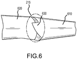
- a vortex generator is illustrated, for example in Figure 6 .
- the delta vortex generator 630 described is incorporated into the cuff, enhancing the effectiveness of the cuff for producing a focused vortex.
- the vortex generator 630 extends the leading edge of the outboard section 610 overlapping the inboard section 620 of the wing. At high angles of attack, airflow passes from beneath the outboard section 610 and around the cuff root and vortex generator.
- the vortex generator 630 energizes the flow, enhancing the creation of an aerodynamic fence.
- Another aspect of the present invention is the inclusion of vortex generators on the wing, above the leading edge, outboard of the cuff.
- the vortex generators add energy to the airflow, reducing boundary layer thickness and enabling the airflow to remain attached to the wing to higher angle of attack.
- Another feature of the present invention is not only the incorporation of a plurality of varied airfoils across the span of the wing, but a wing twist that places the wing root at a higher angle of attack than the wing tip. As the angle of attack of the wing is increased, the wing root will experience a higher local angle of attack than the wing tip and stall first. While the wing twist and the implementation of various airfoils continually varies from root to tip, there is a discrete change at the cuff creating a fence.
- the tail area and span are modified in concert with modifications of the wing to enhance stability and spin resistance.
- the span of the tail is increased and a horizontal tail tip with an increased sweep is added.
- the various combinations of airfoil selection, wing twist, stall strips, wing cuff and vortex generators are fashioned in consideration with the interaction of airflow around the fuselage of an amphibious aircraft.
- the airflow over the inboard sections of the wing area is affected by the airflow over the fuselage and sponson or sea wing.
- the forward position of the sponson or sea wing with respect to the leading edge of the wing acts, in high angle of attack situations, to direct the airflow, reducing the wing's effective angle of attack and therefore its lift.
- the local angle if incidence of the wing in the area of the sponson or seawing can be increased to make up for the seawing-induced loss of lift, thereby promoting the desirable root-first wing stall progression.
- the aircraft develops a stable and isolated stall cell confined to the inboard sections of the wing.
- a significant portion of the outboard section of the wing including a significant portion of both ailerons, retain attached flow.
- the remaining inboard sections of the wing experience either reverse or lateral flow.
- the stall cells remain confined. This confinement of the stall cell promotes spin resistant behavior.
- the present invention provides a spin resistant configuration.
- each individual feature interacts synergistically to create a stable stall cell that is trapped on the inboard portions of the wing.
- the stable and trapped stall cell combined with an emmpanage that remains effective provides the pilot with adequate roll, pitch and yaw control, despite the fact that the wing is in a full stall, to resist entry into a spin.
- flight tests have demonstrated that the stall cell is so well confined that even with full aft controls and full deflection of the rudder, thus inducing yaw into the stall condition, the aircraft remains completely controllable.
- the spin resistant configuration comprises:
- spin resistant configuration for an aircraft can include:
Description
- The present application relates to and claims the benefit of priority to
United States Non-Provisional Patent Application 13/946,572 filed July 19, 2013 United States Provisional Patent Application no. 61/674,267 filed July 20, 2012 - Embodiments of the present invention relate, in general, to aerodynamic techniques designed to deter an aircraft's ability to enter a spin and more particularly to a configuration of said techniques that renders an aircraft spin resistant.
- The primary cause of fatal accidents in small aircraft is loss of control. Loss of control usually occurs because the aircraft enters a flight regime that is outside its normal envelope usually, but not always, at a high rate, thereby introducing an element of surprise for the flight crew. Factors leading to a loss of control are many including loss of situational awareness especially through distraction and/or complacency, intended or unintended mishandling of the aircraft, attempting to maneuver an aircraft outside its capabilities to resolve a prior problem, and the like. While every out of control situation is unique, one loss of control flight regime that every pilot it taught to avoid is a spin.
- In aviation, a spin is an aggravated stall resulting in autorotation about a spin axis wherein the aircraft follows a corkscrew downward path. Stalls in fixed-wing flight are often experienced as a sudden reduction in lift as the pilot increases angle of attack and exceeds the critical angle of attack (which may be due to slowing down below stall speed in level flight). Spins can be entered intentionally or unintentionally, from any flight attitude and from practically any airspeed-all that is required is a sufficient amount of yaw (rotation about a vertical axis) while an aircraft is stalled. In either case, however, a specific and often counterintuitive set of actions may be needed for an effective recovery to be made. If the aircraft exceeds published limitations regarding spins, or is loaded improperly, or if the pilot uses incorrect techniques to recover, the spin can, and often does, lead to a crash.
- In a spin, both wings are in a stalled condition, but one wing will be in a deeper stall condition than the other. This causes the aircraft to autorotate (yaw) towards the deeper-stalled wing due to its higher drag. At the same time, the wings produce an unbalanced amount of lift causing the aircraft to roll and similarly adjust its pitch. An autorotation or spin is thus a stalled condition in which there is simultaneous movement around all three aircraft axes-that is, yaw, pitch, and roll. And as mentioned, a spin results in a vertical flight path. That is to say the aircraft is falling directly to the earth as it spins.
-
Figure 1 is a high level depiction of the interaction of aerodynamic forces acting on a wing going into a spin as is known by one of reasonable skill in the relevant art. For discussion purposes, thewing 100 is divided into two portions designated by the direction the wing portion will go in a spin. In this particular illustration, there is a down-goingwing portion 110 and an up-goingwing portion 120. For an aircraft to spin, the wing must be stalled. In this example, thewing 100 is experiencing an angle of attack that is greater than the critical angle of attack and thus, a stalled condition results. Here both the down-goingwing portion 110 and the up-goingwing portion 120 are experiencing a stalled condition. However in this case, the down-goingwing portion 110 possesses an angle of attack of 40 degrees 130 while the up-goingwing portion 120 has an angle of attack of 25degrees 135. The angle of attack of bothwing portions more drag 140 andless lift 150 than, comparatively, thedrag 145 and thelift 155 of the up-goingwing portion 120. The unbalanced forces result in thewing 100 yawing 160 and rolling 170 simultaneously. - Spins, typified by an excessive angle of attack and slow airspeed, differ from spiral dives which are characterized by low angle of attack and high airspeed. In a spiral dive, the airplane will respond conventionally to the pilot's inputs to the flight controls whereas in a spin, the aircraft's response to flight controls is compromised.
- Some aircraft cannot be recovered from a spin using only their own flight control surfaces. Accordingly, if an aircraft has not been certified for spin recovery, it is assumed that spins are not recoverable and engaging in a spin is considered unsafe in that aircraft. For safety, all certificated, single-engine fixed-wing aircraft, including certificated gliders, must meet specified criteria regarding stall and spin behavior. Complying designs typically have a wing with greater angle of attack at the wing root (the part of the wing that is closest to the fuselage) than at the wing tip, so that the wing root stalls first, reducing the severity of the wing drop at the stall and possibly also allowing the ailerons to remain somewhat effective in controlling the aircraft's rolling movements until the stall migrates outward toward the wing tip. This ideally provides the pilot with some ability to control the aircraft in a stalled condition and preclude a spin from developing.
- Beyond specifying criteria by which an aircraft must demonstrate certain stall and spin behavior, the Code of Federal Regulations that governs Aeronautics and Space, specifically 14 CFR § 23.221 (a)(2), provides criteria by which an aircraft can be demonstrated to be "spin resistant." Prior to the implementation of the present invention, no conventionally-configured aircraft has been able to successfully complete spin-resistance flight testing and demonstrate spin resistance in accordance with the 14 CFR § 23.221(a)(2) standard.
- In the 1970s and 1980s, researchers at NASA's Langley Research Center studied spin resistance in depth, with a focus on aerodynamic characteristics and techniques to make aircraft more resistant to spins. They performed extensive modifications to several aircraft and flew thousands of test flights to determine how changes to the airframe would affect spin characteristics. What they discovered was that small changes could dramatically affect performance during spins. As a result of the study aircraft and according to NASA experimenters, aircraft should be designed to "give plenty of warning, lots of buffet, very little roll-off laterally-a long period of telling the pilot, 'Hey, you're doing something wrong' ."
- One of the key findings of the NASA studies was that a critical component of spin resistance is controlling the way the wing stalls. Experimenters concluded that having the stall initiate near the root of the wing while the outboard panels of the wing continue to fly is ideal because it prevents the stall from fully developing or "breaking" because the outboard panels are still generating lift. Without a stall, a spin cannot initiate.
- Part 23, §23.221 of 14 CFR requires that single-engine airplanes must demonstrate recovery from either a one-turn spin if intentional spins will be prohibited or six-turn spins if intentional spins will be approved. Even more advantageous than an aircraft able to recover from a spin is an aircraft that is resistant to spin entry. Despite decades of research and an understanding of the interaction between stalls and spins, the design of an aircraft meeting the standards of 14 CFR § 23.221has remained a challenge. This and other obstacles of the prior art are addressed by one or more embodiments of the present invention. That is to say, the present invention provides an aircraft configuration that is spin resistant and in compliance with 14 CFR § 23.221 (a)(2).
- Additional advantages and novel features of this invention shall be set forth in part in the description that follows, and in part will become apparent to those skilled in the art upon examination of the following specification or may be learned by the practice of the invention. The advantages of the invention may be realized and attained by means of the instrumentalities, combinations, compositions, and methods particularly pointed out in the appended claims.
- Icon Aircraft Inc.: "About Spins and Spin Resistance" (16.02.2012) Retrieved from the Internet: URL:http://www.iconaircraft.com/news/about-spins-and-spin- resistance.html [retrieved on 2014-04-08] provides an historical summary of efforts over the past several decades to understand characteristics of a spin and its relationship to wing design and wing stalls, and is considered as the closest prior art.
-
US 4334658 discloses a pair of metallic strips are provided for the Cessna Series 150 and 152 aircraft. The strips are secured to the leading edge of the airplane wing at a point substantially adjacent to each wing root. Each strip has a plurality of raised surfaces for modifying the airflow over the upper wing surface, and a concave surface which is placed against the leading edge of the airplane wing. Fasteners placed in recessed areas on the strip secure the strip to the wing's leading edge. The addition of these strips to the airplane wing modify the stall pattern in its area of separated airflow over the upper surface of the wing in such a way that the pilot is provided with aileron control during stalling conditions. -
US 3370810 discloses a device for use when there is the possibility of stall in an aircraft having an aerodynamic-airfoil body which is completely located on the underside of an aircraft wing. The body must be substantially hollow and have a length of at least 50% of the chord length of the wing. The nose of the device must extend forward of the wing leading edge sufficiently to intersect the air stagnation streamline near aircraft stall. -
US 20100123047 discloses a Blended Wing Body SUAV and MUAV having an airfoil profile, wing configuration, rigging and tractor pull propeller placement that provides stability and safety characteristics. This blended wing design includes wing twist on the outboard wing and an inverted "W" shaped planform to provide lateral and longitudinal stability, and smooth, even flight characteristics throughout the range of the expected flight envelope. -
GB 407009 -
US 2964271 discloses an amphibious aircraft capable of taking off and landing upon either a solid ground or water surface. - The present teaching provides a configuration as detailed in claim 1. Also provided is a system according to claim 8. Advantageous features are provided in dependent claims.
- Hereafter described in various embodiments and by way of example is a configuration and system for rendering an aircraft spin resistant. Resistance of the aircraft to spinning is accomplished by constraining a stable stall cell or pattern of stall cells to a wing region adjacent to the fuselage and distant from the wing tip.
- According to one embodiment of the present invention, a wing is comprised of two contiguous regions. A first region is adjacent to the fuselage and a second region is adjacent to the wing tip. A cuff operable to form a boundary between the first region and the second region is included in one embodiment. The inclusion of this cuff introduces energy into the airflow such that an aerodynamic fence is established on the upper surface of the aircraft and subsequently inhibits the progression of the stall cell from the first region toward the second region.
- In accordance with another embodiment, the first region of the wing includes one or more stall strips, which function as fixed aerodynamic devices operable to modify the airfoil and, consequently, the airflow around the airfoil. In an exemplary embodiment, stall strips act in concert with characteristics of the fuselage and wing to create a condition that, when the aircraft is in a high angle of attack condition, the airflow interaction between the root and the wing is such that the stall is initiated first at the root and progresses outward toward the wing tip.
- Yet another embodiment of the present invention locates one or more vortex generators on one or more portions of the wing. The vortex generators operate to delay airflow separation on the section of the wing adjacent to the wing tip, thus constraining the stall to the wing region adjacent to the fuselage.
- The configuration of the wing includes a wing twist, thereby initiating a stalled condition first at the root that then progresses outward toward the wing tip as the angle of attack increases.
- The wing configuration of the present invention, in accordance with yet another embodiment, comprises a forward-swept outboard wing panel, which allows that portion of the wing to maintain attached airflow sufficient to provide positive control characteristics.
- Alone or, preferably, in combination, the aircraft configuration features embodied by the present invention render the aircraft spin resistant by constraining a stable stall cell or pattern of cells to the wing region adjacent to the fuselage, which permits control surfaces of the aircraft to remain operational to control the aircraft.
- The features and advantages described in this disclosure and in the following detailed description are not all-inclusive. Many additional features and advantages will be apparent to one of ordinary skill in the relevant art in view of the drawings, specification, and claims hereof. Moreover, it should be noted that the language used in the specification has been principally selected for readability and instructional purposes and may not have been selected to delineate or circumscribe the inventive subject matter; reference to the claims is necessary to determine such inventive subject matter.
- The aforementioned and other features and objects of the present invention and the manner of attaining them will become more apparent, and the invention itself will be best understood, by reference to the following description of one or more embodiments taken in conjunction with the accompanying drawings, wherein:
-
Figure 1 is a depiction of aerodynamic conditions present in a spin as would be known to one of reasonable skill in the relevant art; -
Figure 2 illustrates a planform (outline of an object as viewed from above) view of a spin resistant wing configuration and associated stalled airflow characteristics according to one embodiment of the present invention; -
Figure 3 shows an angular implementation of an inboard (toward the center line) stall strip as associated with one embodiment of a spin resistant configuration of the present invention; -
Figure 4 depicts an implementation of dual overlapping stall strips as associated with one embodiment of a spin resistant configuration of the present invention; -
Figure 5 is a combined planform, front and end view of a wing associated with one embodiment of a spin resistant configuration of the present invention; and -
Figure 6 shows one embodiment of a wing cuff root vortex generator (operable to, for example, delay airflow separation along the wing/fuselage juncture) as associated with one embodiment of a spin resistant configuration of the present invention. - The Figures depict embodiments of the present invention for purposes of illustration only. One skilled in the art will readily recognize from the following discussion that alternative embodiments of the structures and methods illustrated herein may be employed without departing from the principles of the invention described herein.
- Disclosed hereafter by way of example is a novel configuration of aerodynamic features that results in an aircraft that is fully spin resistant. According to one embodiment of the present invention, the interaction of various aerodynamic techniques results in an aircraft that is resistant to spin entry throughout the flight test envelope stated in the United States Federal Aviation Administration ("FAA") Regulations. One aspect of the present configuration/combination is a cuffed wing design that employs multiple proprietary airfoils across the span of the wing that controls the progression of a stall to create a stabilized stall cell. This discontinuity on the leading edge of the wing delineates the wing into two distinct regions. The outboard (away from the center line) segments of cuffed wings have a different airfoil with a drooped leading edge as compared to the inboard segments of the wing, which causes the outboard portion of the wing to stall later than the inboard portion of the wing as angle of attack increases. Because the ailerons are located on the outboard panel that is still lifting, roll control is preserved even after the inboard panel of the wing has fully stalled. Accordingly, the root sections of the wing possess higher angles of attack across the span and thus stall before the wing tip or outboard portions of the wing. The cuff also operates as a fence, trapping separated airflow to inboard sections of the wing, while the airflow associated with the outboard sections of the wing remains attached to the wing. The cuff in this aspect acts as large vortex generator whose vortex is shed over the upper surface of the wing trapping separated airflow to the inboard sections. These and other features of the present invention form a configuration that is spin resistant.
- Many types of airplanes will spin when the pilot simultaneously yaws and stalls the airplane (intentionally or unintentionally). One common scenario that can lead to an unintentional spin is an uncoordinated turn towards the runway during the landing sequence. A pilot who is overshooting the turn to final approach may be tempted to apply rudder to increase the rate of turn. The result is twofold: the nose of the airplane drops below the horizon and the bank angle increases. Reacting to these unintended changes, the pilot may then begin to pull the elevator control aft (toward the tail of the aircraft, thus increasing the angle of attack) while applying opposite aileron to decrease the bank angle. Taken to its extreme, this cross-control input can result in an uncoordinated turn with sufficient angle of attack to cause the aircraft to stall. This is called a cross-control stall, and is very dangerous if it happens at low altitude where the pilot has little time to recover. Add in a little yaw and the loss of control can quickly evolve into a spin. To avoid this scenario, pilots are taught the importance of always making coordinated turns and avoiding situations that require last minute corrections.
- The spinning equation is further complicated by individual aircraft characteristics. For example, the likelihood of an aircraft entering a spin is significantly influenced by the position of the center of gravity. In general terms, the further forward the center of gravity is, the less readily the airplane will spin and the more readily the airplane will recover from a spin. Conversely, the further aft the center of gravity is, the more readily the airplane will spin and the less readily the airplane will recover from a spin. In any airplane, the forward and aft limits on center of gravity are carefully defined. In some airplanes that are approved for intentional spinning, the aft limit at which spins may be attempted is not as far aft as the aft limit for general flying.
- One or more embodiments of the present invention present a configuration of an amphibious aircraft that is spin resistant. An amphibious aircraft or amphibian is an aircraft that can take off and land on both land and water. Amphibians are fixed-wing aircraft that are equipped with retractable wheels, at the expense of extra weight and complexity, plus diminished range and fuel economy compared to planes designed for either land or water only.
- While amphibious aircraft exhibit many of the same flight characteristics as land-based aircraft, they do possess unique aerodynamic features and center of gravity concerns. For example, the lower portion of the aircraft is a watercraft hull and as the aircraft must obtain speeds sufficient to transition to flight, it must plane on top of the water. These characteristics cannot only influence the center of gravity but can also create drag in a high angle of attack situation.
- Embodiments of the present invention introduced above are hereafter described in detail with reference to the accompanying Figures. Although the invention has been described and illustrated with a certain degree of particularity, it is understood that the present disclosure has been made only by way of example and that numerous changes in the combination and arrangement of parts can be resorted to by those skilled in the art without departing from the spirit and scope of the invention.
- The following description with reference to the accompanying drawings is provided to assist in a comprehensive understanding of exemplary embodiments of the present invention as defined by the claims and their equivalents. It includes various specific details to assist in that understanding but these are to be regarded as merely exemplary. Like numbers refer to like elements throughout. In the figures, the sizes of certain lines, layers, components, elements or features may be exaggerated for clarity. Accordingly, those of ordinary skill in the art will recognize that various changes and modifications of the embodiments described herein can be made without departing from the scope and spirit of the invention. Also, descriptions of well-known functions and constructions are omitted for clarity and conciseness.
- The angle of attack of an aircraft is the acute angle between an aircraft's mean wing chord or other defined aircraft longitudinal axis and the direction of the relative free stream wind. A chord line is a line drawn from the trailing edge of the wing to the farthest forward point on the leading edge of the wing.
- A stall is a condition in aerodynamics and aviation wherein the angle of attack increases beyond a certain point such that the lift begins to decrease and drag increases. The angle at which this occurs is called the critical angle of attack. This critical angle is dependent upon the profile of the wing, its planform, its aspect ratio, and other factors, but is typically in the range of 8 to 20 degrees relative to the incoming wind for most subsonic airfoils. The critical angle of attack is the angle of attack on the lift coefficient versus angle-of-attack curve at which the maximum lift coefficient occurs.
- An airfoil is the shape of a wing as seen in a cross section. The airfoil shape produces aerodynamic forces resulting in lift. Most foil shapes require a positive angle of attack to generate lift, but cambered airfoils can generate lift at zero angle of attack. This "turning" of the air in the vicinity of the airfoil creates curved streamlines which results in lower pressure on one side and higher pressure on the other. This pressure difference is accompanied by a velocity difference, via Bernoulli's principle, so the resulting flow-field about the airfoil has a higher average velocity on the upper surface than on the lower surface.
- The terminology used herein is for the purpose of describing particular embodiments only and is not intended to be limiting of the invention. As used herein, the singular forms "a," "an" and "the" are intended to include the plural forms as well, unless the context clearly indicates otherwise. Thus, for example, reference to "a component surface" includes reference to one or more of such surfaces.
- As used herein, the terms "comprises," "comprising," "includes," "including," "has," "having" or any other variation thereof, are intended to cover a non-exclusive inclusion. For example, a process, method, article, or apparatus that comprises a list of elements is not necessarily limited to only those elements but may include other elements not expressly listed or inherent to such process, method, article, or apparatus. Further, unless expressly stated to the contrary, "or" refers to an inclusive or and not to an exclusive or. For example, a condition A or B is satisfied by any one of the following: A is true (or present) and B is false (or not present), A is false (or not present) and B is true (or present), and both A and B are true (or present).
- Unless otherwise defined, all terms (including technical and scientific terms) used herein have the same meaning as commonly understood by one of ordinary skill in the art to which this invention belongs. It will be further understood that terms, such as those defined in commonly used dictionaries, should be interpreted as having a meaning that is consistent with their meaning in the context of the specification and relevant art and should not be interpreted in an idealized or overly formal sense unless expressly so defined herein. Well-known functions or constructions may not be described in detail for brevity and/or clarity.
- It will be also understood that when an element is referred to as being "on," "attached" to, "connected" to, "coupled" with, "contacting", "mounted" etc., another element, it can be directly on, attached to, connected to, coupled with or contacting the other element or intervening elements may also be present. In contrast, when an element is referred to as being, for example, "directly on," "directly attached" to, "directly connected" to, "directly coupled" with or "directly contacting" another element, there are no intervening elements present. It will also be appreciated by those of skill in the art that references to a structure or feature that is disposed "adjacent" another feature may have portions that overlap or underlie the adjacent feature.
- Spatially relative terms, such as "under," "below," "lower," "over," "upper" and the like, may be used herein for ease of description to describe one element or feature's relationship to another element(s) or feature(s) as illustrated in the figures. It will be understood that the spatially relative terms are intended to encompass different orientations of a device in use or operation in addition to the orientation depicted in the figures. For example, if a device in the figures is inverted, elements described as "under" or "beneath" other elements or features would then be oriented "over" the other elements or features. Thus, the exemplary term "under" can encompass both an orientation of "over" and "under". The device may be otherwise oriented (rotated 90 degrees or at other orientations) and the spatially relative descriptors used herein interpreted accordingly. Similarly, the terms "upwardly," "downwardly," "vertical," "horizontal" and the like are used herein for the purpose of explanation only unless specifically indicated otherwise.
-
Figure 2 shows a high-level plan view depiction of a wing associated with the spin resistant configuration according to one embodiment of the present invention. Thewing 200 can be considered to be divided into two sections, anoutboard wing section 210 andinboard wing section 220. The two portions of the wing are separated by awing cuff 215 on the leading edge located in one embodiment at 50% of the wing semi-span. In other embodiments the cuff can be positioned farther outboard with locations ranging between 50 and 70% of the wing semi-span. Outboard of thewing cuff 215 the leading edge sweeps backwards slightly while the trailing edge includes a slight forward sweep. The wingtip includes an anhedral / dihedral combination with a rearward extending feature.Figure 2 further includes the on-body airflow characteristics of the wing in a full stall condition. As can be seen, theinboard section 220 presents a classic reverse airflow orseparated airflow phenomena 240 while theoutboard section 210 of the wing maintains attachedairflow 250. Thewingtip 230 also experiences minor vortex generation.Figure 2 illustrates that thewing 200 in a full stall condition maintains suitable airflow across control surfaces (the ailerons are located on the outboard section of the wing) to maintain control of the aircraft. While the wing may not be able to provide adequate lift to support level flight, portions of the wing maintain attached airflow sufficient to provide positive control characteristics. - As described in more detail below, the
wing cuff 215 introduces energy into the airflow such that an aerodynamic fence is established on the upper surface of the wing. The fence inhibits the progression of the stall, separated airflow, outboard of aline 260 running from thecuff 215 to the trailing edge. - Another aspect of one embodiment of the spin resistant design of the present invention is the inclusion of a stall strip near the wing root.
Figure 3 shows an angular implementation of a stall strip located on near theroot 330 of awing 200 according to one embodiment of the present invention. A stall strip is a fixed aerodynamic device employed on a fixed-wing aircraft to modify the airfoil. Stall strips are usually employed in pairs, symmetrically on both wings. In rare installations, they are employed as a single strip on one wing to correct aberrant stall behavior. Normally stall strips are employed to generate a stalled condition near the root of the wing so as to produce turbulent airflow over the tail control surfaces prior to the stall of the entire wing. In such a manner, the impending stall is communicated to the pilot. - One or more stall strips located on the inboard section of the wing are positioned to initiate and stabilize an integer number of stall cells on the inboard section of the wing. In an exemplary embodiment, a wing with an aspect ratio of 9 and a wing cuff root located at 60% of the wing semi-span, a stall strip is positioned at the mid-span of the inboard section of the wing. In this position, the stall strip is operable to initiate and hold a single stall cell on the inboard section of the wing.
- Stall strips act in concert with the characteristics of the fuselage and wing to create a condition that, when the aircraft is in a high angle of attack condition, the airflow interaction between the root and the wing is such that the stall is initiated first at the root and progresses outward toward the wing tip. As can be seen in
Figure 3 , thestall strip 320 is positioned near theroot 330 of thewing 200 and oriented diagonally downward as seen from the front of the aircraft along a span such that the highest portion of thestall strip 320 is at theroot 330 above the leading edge and the lowest portion of thestall strip 320 extends downward in the direction of the wing tip toward the leading edge. The angular orientation of the stall strip is combined with a wing twist (discussed below) that initiates a stalled condition first at theroot 330 and then progresses outward as the angle of attack is increased. - As shown in
Figure 4 , a pair of stall strips are positioned on the leading edge of the inboard section of the wing to control stall progression. Before intersecting the leading edge of thewing 200 the first orprimary stall strip 410 concludes and is overlapped 430 by asecond stall strip 420. The second orsecondary stall strip 420 begins slightly inboard of the termination of theprimary stall strip 410 and continues outward along the leading edge of the wing for a predetermined distance before it terminates. In one embodiment, thesecondary stall strip 420 concludes prior to reaching thecuff 215. - The stall strips are aligned with the leading edge of the wing and positioned to form a stable stall cell (as shown in
Figure 2 ) beginning at the fuselage and extending to the cuff. In yet other embodiments, the stall strips are curved with respect to the leading edge, wing twisted and airfoil varied to control the progression of the stall as the critical angle of attack is reached. As mentioned above with reference toFigure 2 , the vortex generated by thecuff 215 also translates outward toward the wing tip as it interacts with separated, reverse flow on theinboard sections 220 of thewing 200 and turbulent but remains as attached flow on theoutboard sections 210 of thewing 200. - Turning attention in addition to
Figure 5 , one can see a combined planform, front and end view of a wing associated with one embodiment of a spin resistant configuration of the present invention. Thecuff 215 portion of the present invention not only extends the cord of thewing 200 forward but also lowers the leading edge at a discrete position along the span of thewing 200. The effect of thecuff 215 along with varied airfoils along the span of thewing 200 is to create an aerodynamic fence via a vortex that traps separated airflow on theinboard section 220 of thewing 200. Accordingly, while theinboard section 220 of thewing 200 is in a full stall, the airflow associated with theoutboard section 210 of thewing 200 remains attached. In another embodiment, a cuff segment is incorporated into the wing rather than a single or unilateral notch as shown inFigure 5 . This type of segment cuff produces bilateral opposing voracities as opposed to a unilateral vortex. Moreover, the segmented cuff can be combined with a unilateral or typical cuff so as to render multiple barriers operable to stabilize and control the stall cell. - In yet another embodiment, different wing cuff sections are included in the profile of the wing's span, each with different configurations. The introduction of multiple cuffs produces one or more pronounced and controllable fences, trapping the stall cell. Stall strips, as described above, are incorporated inboard of the cuff to enhance the separation of flow on the inboard section of the wing at a high angle of attack.
- Another aspect of the present invention is the inclusion of washout to the inboard or outboard wing segments. According to one embodiment, 1.5 degrees of washout is included in the wing. For the purpose of this description, washout is defined as wing twist such that the wing incidence decreases from inboard wing stations towards outboard stations. Other embodiments of the present invention include other distributions of wing twist. Exemplary embodiments of the present invention include a wing twist of 0.5 degrees up to 3 degrees.
- Along the span of the
wing 200 one configuration aspect of the present invention that aids in its ability to be spin resistant is not only the twist of the wing but the ability to vary the airfoil along the span of the wing.Figure 5 identifies, in one embodiment, five distinct positions in which thewing 200 exhibits a different airfoil shape and/or configuration. In some cases, the airfoil size, that is to say the chord length and angular orientation, may vary while in other embodiments, the airfoil shape may vary. In the latter case, thewing 200 begins at the root with a firstairfoil cross section 510 that remains constant for a portion ofinboard section 220 of wing. At approximately 50% semi-span, the airfoil changes from theinner profile 520 to that of aninner cuff profile 530. Throughout this section the leading edge and trailing edge remain the same (i.e. the wing has no twist). At thecuff 215, the leading edge of theairfoil 535 is extended forward while the trailing edge remains coincident. This is the longest chord length of thewing 200. From this point to the wingtip, thewing 200 tapers with the leading edge retreating and the trailing edge sweeping forward. Approximately 25% of the distance from thecuff root 215 to the wingtip, afifth airfoil configuration 540 can be seen. The airfoil andwing 200 continues to vary continuously to the wingtip at which awingtip airfoil 550 transitions into ananhedral wing tip 555 with a retreatingtrailing edge 560. - In other combinations of the present invention the location and amount of wing taper and trailing edge forward sweep can vary so as to maximize the ability to trap and control the placement of the stall cell near the wing root.
- In the one embodiment, a wing cuff is positioned at 50% semi-span with vortex generators, angled at 15 degrees to the aircraft longitudinal axis and positioned on the outboard wing panel. Each vortex generator is spaced by 3 inches. To energize the airflow and in other embodiments of the present invention the vortex generators are spaced between 2 and 4 inches with the angle of each generator ranging from 10 to 20 degrees to the aircraft longitudinal axis. Finally, stall strips are located on the inboard section of the wing, that is, inboard of the cuff, as described above. The most inboard stall strip is angled downward at 7 degrees (front view, root to wing tip) and located at 11-25% semi-span with another stall strip located outboard of the first at positions 24-35% semi-span parallel to the leading edge. As one of reasonable skill in the relevant art can appreciate the location and angular variation of the stall strips can vary. Indeed while the present embodiment presents a linear stall strip disposed at 7 degrees from the leading edge, other embodiments can have more or less of an angular orientation based on the wing twist in that particular section and alterations of the effective or local angle of attack. For example a wingspan having a more pronounced wing twist may have the stall strips less angled to overall provide a similar stall initiation phenomena at the root. Also the stall strip itself may be curvilinear rather than straight based again on the stall initiation and stall cell characteristics. The stall strips are arranged and orientated to make sure that the stall is initiated at the root and progresses in a controlled manner so that stall cell can be captured apart from any control surfaces which, under separated flow of a stall, can be rendered ineffective.
- The angle of incidence is modified along the span of the wing such that at 0-19% semi-span, it is 5 degrees and changes to 2 degrees at 60% semi-span. The wing twist then further reduces to 1 degree at the wing tip (100% semi-span). In this embodiment, the wing cuff is positioned at 60% semi-span and vortex generators, angled at 15 degrees and spaced by 3 inches, are located on the outboard wing panel at 10% chord. Finally, a single stall strip is located at 33-39% wing semi-span which is parallel to the leading edge.
- In another embodiment, one or more delta vortex generators attached to the leading edge of the wing can also be employed to generate a strong vortex at a certain position along the wing span that are operable to restrict the stall to the inboard sections of the wing. Such a vortex generator is illustrated, for example in
Figure 6 . As shown, thedelta vortex generator 630 described is incorporated into the cuff, enhancing the effectiveness of the cuff for producing a focused vortex. Thevortex generator 630 extends the leading edge of theoutboard section 610 overlapping theinboard section 620 of the wing. At high angles of attack, airflow passes from beneath theoutboard section 610 and around the cuff root and vortex generator. Thevortex generator 630 energizes the flow, enhancing the creation of an aerodynamic fence. - Another aspect of the present invention is the inclusion of vortex generators on the wing, above the leading edge, outboard of the cuff. The vortex generators add energy to the airflow, reducing boundary layer thickness and enabling the airflow to remain attached to the wing to higher angle of attack. Another feature of the present invention is not only the incorporation of a plurality of varied airfoils across the span of the wing, but a wing twist that places the wing root at a higher angle of attack than the wing tip. As the angle of attack of the wing is increased, the wing root will experience a higher local angle of attack than the wing tip and stall first. While the wing twist and the implementation of various airfoils continually varies from root to tip, there is a discrete change at the cuff creating a fence.
- To further enhance the aircraft's resistant to a spin, the tail area and span are modified in concert with modifications of the wing to enhance stability and spin resistance. To improve longitudinal stability, the span of the tail is increased and a horizontal tail tip with an increased sweep is added.
- The combinations of features described above with respect to the wing are also enhanced by their relationship to the aircraft fuselage. In one embodiment of the present invention, the various combinations of airfoil selection, wing twist, stall strips, wing cuff and vortex generators are fashioned in consideration with the interaction of airflow around the fuselage of an amphibious aircraft. In a high wing configuration on top of a fuselage that includes a sponson or sea wing, the airflow over the inboard sections of the wing area is affected by the airflow over the fuselage and sponson or sea wing. The forward position of the sponson or sea wing with respect to the leading edge of the wing acts, in high angle of attack situations, to direct the airflow, reducing the wing's effective angle of attack and therefore its lift. As a result, the local angle if incidence of the wing in the area of the sponson or seawing can be increased to make up for the seawing-induced loss of lift, thereby promoting the desirable root-first wing stall progression.
- As the Figures illustrate, the aircraft develops a stable and isolated stall cell confined to the inboard sections of the wing. At full control input, a significant portion of the outboard section of the wing, including a significant portion of both ailerons, retain attached flow. The remaining inboard sections of the wing experience either reverse or lateral flow. Despite rolling or yawing the aircraft, the stall cells remain confined. This confinement of the stall cell promotes spin resistant behavior.
- The present invention provides a spin resistant configuration. By combining the features of the present invention in a coordinated manner, each individual feature interacts synergistically to create a stable stall cell that is trapped on the inboard portions of the wing. The stable and trapped stall cell combined with an emmpanage that remains effective provides the pilot with adequate roll, pitch and yaw control, despite the fact that the wing is in a full stall, to resist entry into a spin. Indeed flight tests have demonstrated that the stall cell is so well confined that even with full aft controls and full deflection of the rudder, thus inducing yaw into the stall condition, the aircraft remains completely controllable.
- Preferred embodiments of the present invention are outlined below. In one embodiment the spin resistant configuration comprises:
- a fuselage and a wing wherein the wing includes a first region adjacent to the fuselage and a second region adjacent to a wing tip, the first region being contiguous with the second region, and wherein at high angles of attack a stall cell is constrained to remain within the first region so as to remain apart from flight controls within the second region.
- Other features of the spin resistant configuration for an aircraft can include:
- wherein the wing includes a cuff operable to form an aerodynamic boundary between the first region and the second region.
- wherein the cuff includes a delta vortex generator.
- wherein the first region includes one or more stall strips associated with a leading edge of the wing.
- wherein at least one of the one or more stall strips is coupled to the leading edge of the wing and angled downward as it extends toward the wing tip.
- wherein at least one of the one or more stalls strips is coupled to and parallel with the leading edge of the wing.
- wherein the second region includes vortex generators.
- wherein the wing includes a wing twist such that a wing tip angle of incidence is less than a wing root angle of incidence.
- wherein the wing twist of the first region is substantially different from the wing twist of the second region.
- wherein the wing tip is swept forward.
- wherein the aircraft is an amphibious aircraft that includes sponsons.
- wherein at high angles of attack the sponsons reduce an effective angle of attack of the wing near the fuselage.
- Other features of a configuration system for a spin resistant aircraft can include:
- a wing having root and a wing tip and wherein the wing includes a first region near the wing root and a second region near the wing tip and wherein the first region and the second region are contiguous along a contiguous border; and
- a leading edge discontinuity operable at high angles of attack to form an aerodynamic fence along the contiguous border isolating a stall cell to the remain within the first region apart from any control surfaces in the second region.
- Features of a spin resistant configuration described above can include:
- wherein responsive to a stall cell being developed within the first region, control surfaces of the aircraft remain operational to control the aircraft.
- wherein aircraft control surfaces are isolated from the stall cell.
- a plurality of vortex generators associated with the second region.
- one or more stall strips associated with a leading edge of the wing in the first region.
- wherein one of the one or more stalls strips is coupled to the leading edge of the wing and angled downward as it extends toward the wingtip.
- wherein one of the one or more stall strips is coupled to and parallel with the leading edge of the wing.
- wherein the wing includes a wing twist such that a wing tip angle of incidence is less than a wing root angle of incidence.
- wherein the wing twist of the first region is substantially different from the wing twist of the second region.
- wherein the aircraft is an amphibious aircraft having sponsons and
wherein the wing twist at the root is increased due to an effective angle of attack reduction due to the sponsons. - Upon reading this disclosure, those of skill in the art will appreciate still additional alternative structural and functional designs for a system and a process for a spin resistant aircraft configuration through the disclosed principles herein. Thus, while particular embodiments and applications have been illustrated and described, it is to be understood that the disclosed embodiments are not limited to the precise construction and components disclosed herein. Various modifications, changes and variations, which will be apparent to those skilled in the art, may be made in the arrangement, operation and details of the method and apparatus disclosed herein without departing from the spirit and scope defined herein.
- It will also be understood by those familiar with the art, that the invention may be embodied in other specific forms without departing from the spirit or essential characteristics thereof. Although the invention has been described and illustrated with a certain degree of particularity, it is understood that the present disclosure has been made only by way of example and that numerous changes in the combination and arrangement of parts can be resorted to by those skilled in the art without departing from the spirit and scope of the invention, as hereinafter claimed.
Claims (12)
- An aircraft so as to be spin resistant, said aircraft comprising:a fuselage; anda wing wherein the wing includes a first region (220) adjacent to the fuselage and a second region (210) adjacent to a wing tip, the first region being contiguous with the second region, a variable wing twist (510-550) such that a wing tip angle of incidence is less than a wing root angle of incidence, one or more stall strips (320, 410, 420) attached to a leading edge of the first region of the wing and configured to be aligned with the leading edge of the wing a wing cuff (215) positioned between the first region and the second region and configured to form an aerodynamic boundary (260) between the first region and the second region at high angles of attack so as to constrain a stall cell (240) to remain within the first region and apart from flight controls within the second region.
- The aircraft as defined in claim 1, wherein the cuff (215) includes a delta vortex generator (630).
- The aircraft as defined in claim 1, wherein the first region (220) includes one or more stall strips (320, 410, 420) associated with a leading edge of the wing.
- The aircraft as defined in claim 1, wherein the second region includes vortex generators (630).
- The aircraft as defined in claim 1, wherein the wing tip is swept forward.
- The aircraft as defined in claim 1, wherein the aircraft is an amphibious aircraft that includes sponsons.
- The aircraft as defined in claim 6, wherein at high angles of attack the sponsons reduce an effective angle of attack of the wing near the fuselage.
- A system for a spin resistant configuration in an aircraft, the system comprising:a wing having root and a wing tip wherein the wing includes a first region (220) near the wing root and a second region (210) near the wing tip and wherein the first region and the second region are contiguous along a contiguous border, a variable wing twist (510-550) such that a wing tip angle of incidence is less than a wing root angle of incidence, and one or more stall strips (320, 410, 420) attached to a leading edge of the first region of the wing and configured to be aligned with the leading edge of the wing ; anda leading edge discontinuity (215) operable at high angles of attack to form an aerodynamic fence (260) along the contiguous border isolating a stall cell (240) to the remain within the first region apart from any control surfaces in the second region.
- The system for a spin resistant configuration in the aircraft according to claim 8, wherein responsive to a stall cell being developed within the first region, control surfaces of the aircraft remain operational to control the aircraft.
- The system for a spin resistant configuration in the aircraft according to claim 9, wherein aircraft control surfaces are isolated from the stall cell.
- The system for a spin resistant configuration in the aircraft according to claim 8, further comprising a plurality of vortex generators (630) associated with the second region.
- The system for a spin resistant configuration in the aircraft according to claim 8, wherein the aircraft is an amphibious aircraft having sponsons and wherein the wing twist (510-550) at the root is increased due to an effective angle of attack reduction due to the sponsons.
Applications Claiming Priority (2)
| Application Number | Priority Date | Filing Date | Title |
|---|---|---|---|
| US201261674267P | 2012-07-20 | 2012-07-20 | |
| PCT/US2013/051355 WO2014074182A1 (en) | 2012-07-20 | 2013-07-19 | Spin resistant aircraft configuration |
Publications (2)
| Publication Number | Publication Date |
|---|---|
| EP2874873A1 EP2874873A1 (en) | 2015-05-27 |
| EP2874873B1 true EP2874873B1 (en) | 2016-12-14 |
Family
ID=49945732
Family Applications (1)
| Application Number | Title | Priority Date | Filing Date |
|---|---|---|---|
| EP13827053.3A Active EP2874873B1 (en) | 2012-07-20 | 2013-07-19 | Spin resistant aircraft configuration |
Country Status (10)
| Country | Link |
|---|---|
| US (3) | US9327828B2 (en) |
| EP (1) | EP2874873B1 (en) |
| CN (1) | CN104203748B (en) |
| AU (2) | AU2013341766B2 (en) |
| BR (1) | BR112015000821B1 (en) |
| CA (1) | CA2878905C (en) |
| ES (1) | ES2620628T3 (en) |
| MX (1) | MX363459B (en) |
| RU (1) | RU2640669C2 (en) |
| WO (1) | WO2014074182A1 (en) |
Families Citing this family (11)
| Publication number | Priority date | Publication date | Assignee | Title |
|---|---|---|---|---|
| RU2640669C2 (en) * | 2012-07-20 | 2018-01-11 | Айкон Айркрафт, Инк. | Aircraft configuration having spin resistance |
| US8939410B2 (en) * | 2013-02-06 | 2015-01-27 | Reginald J Exton | Boundary layer flow disruptors for delaying transition to turbulent flow |
| US10239606B2 (en) * | 2013-12-04 | 2019-03-26 | Tamarack Aerospace Group, Inc. | Airflow interrupting devices |
| US20150361951A1 (en) * | 2014-06-17 | 2015-12-17 | Siemens Energy, Inc. | Pressure side stall strip for wind turbine blade |
| FR3039129B1 (en) * | 2015-07-20 | 2017-07-07 | Airbus Helicopters | AIRCRAFT FUSELAGE FIN AND ASSOCIATED AIRCRAFT |
| DK178874B1 (en) * | 2015-08-19 | 2017-04-18 | Envision Energy (Jiangsu) Co Ltd | Wind turbine blade with tripping device and method thereof |
| DE102019202354A1 (en) * | 2019-02-21 | 2020-08-27 | HORTEN Aircraft GmbH | Brushless aircraft |
| CN110920866A (en) * | 2019-11-18 | 2020-03-27 | 北京航空航天大学 | Method for restraining airplane rock motion through wing spoiler |
| US11440644B2 (en) * | 2020-02-21 | 2022-09-13 | Textron Innovations Inc. | Download reducing winglets for aircraft having a rotor producing downwash and method of operating the same |
| CN111924086B (en) * | 2020-07-07 | 2021-12-10 | 北京机电工程研究所 | Deformable mechanism driven by memory alloy |
| US11869877B2 (en) | 2021-08-06 | 2024-01-09 | Sandisk Technologies Llc | Bonded assembly including inter-die via structures and methods for making the same |
Family Cites Families (28)
| Publication number | Priority date | Publication date | Assignee | Title |
|---|---|---|---|---|
| GB407009A (en) * | 1932-09-07 | 1934-03-07 | Vickers Aviat Ltd | Improvements in or connected with cantilever wings for aircraft |
| US2210642A (en) * | 1938-05-27 | 1940-08-06 | Stephen W Thompson | Aircraft |
| US2369832A (en) * | 1942-12-14 | 1945-02-20 | Cons Vultee Aircraft Corp | Airplane aileron system |
| US2964271A (en) * | 1956-12-17 | 1960-12-13 | Theodore R Strawn | Amphibian aircraft |
| US3370810A (en) * | 1966-02-01 | 1968-02-27 | Mc Donnell Douglas Corp | Stall control device for swept wings |
| US4323209A (en) * | 1977-07-18 | 1982-04-06 | Thompson Roger A | Counter-rotating vortices generator for an aircraft wing |
| US4334658A (en) * | 1979-04-06 | 1982-06-15 | Mackenzie Sprague B | Stalling aerodynamics of the Cessna models 150 and 152 series aircraft |
| US4354648A (en) * | 1980-02-06 | 1982-10-19 | Gates Learjet Corporation | Airstream modification device for airfoils |
| US4334654A (en) | 1980-05-13 | 1982-06-15 | Akzona, Incorporated | Apparatus and method for controlling the tension on a yarn bundle withdrawn from a mass of compacted yarn |
| SU1840516A1 (en) * | 1983-03-21 | 2007-05-27 | Федеральное государственное унитарное предприятие "Центральный аэрогидродинамический институт им. профессора Н.Е. Жуковского" | Flying vehicle |
| US4706910A (en) * | 1984-12-27 | 1987-11-17 | The United States Of America As Represented By The Administrator Of The National Aeronautics And Space Administration | Combined riblet and lebu drag reduction system |
| DE3521329A1 (en) * | 1985-06-14 | 1986-12-18 | Messerschmitt-Bölkow-Blohm GmbH, 8012 Ottobrunn | Vortex generator and boundary layer deflector arrangement |
| US4776542A (en) * | 1987-05-27 | 1988-10-11 | Vigyan Research Associates, Inc. | Aircraft stall-spin entry deterrent system |
| US5253828A (en) * | 1992-07-17 | 1993-10-19 | The Board Of Regents Of The University Of Oklahoma | Concealable flap-actuated vortex generator |
| US5634613A (en) * | 1994-07-18 | 1997-06-03 | Mccarthy; Peter T. | Tip vortex generation technology for creating a lift enhancing and drag reducing upwash effect |
| US5598990A (en) * | 1994-12-15 | 1997-02-04 | University Of Kansas Center For Research Inc. | Supersonic vortex generator |
| US5772155A (en) * | 1996-06-01 | 1998-06-30 | Nowak; Dieter K. | Aircraft wing flaps |
| ITMI20012170A1 (en) * | 2001-10-18 | 2003-04-18 | Aermacchi S P A | IMPROVED AERODYNAMIC AIRCRAFT CONFIGURATION |
| US6578798B1 (en) * | 2002-04-08 | 2003-06-17 | Faruk Dizdarevic | Airlifting surface division |
| US7234914B2 (en) * | 2002-11-12 | 2007-06-26 | Continum Dynamics, Inc. | Apparatus and method for enhancing lift produced by an airfoil |
| US7503527B1 (en) * | 2004-01-22 | 2009-03-17 | Fairchild Mark D | Flight control method and apparatus to produce induced yaw |
| DE102004045732A1 (en) * | 2004-09-21 | 2006-03-30 | Airbus Deutschland Gmbh | Airplane e.g. passenger airplane has control device which acts on trailing-edge flaps and stallstrips to reduce maximum possible lift of wings when actual wing load reaches predetermined value |
| US7537182B2 (en) * | 2004-09-23 | 2009-05-26 | The United States Of America As Represented By The Administrator Of The National Aeronautics And Space Administration | Simultaneous multiple-location separation control |
| US8152109B2 (en) * | 2007-11-29 | 2012-04-10 | Silich Bert A | Method and system for controlling fluid flow in relation to a foil and harnessing energy therefrom |
| US20100123047A1 (en) * | 2008-11-14 | 2010-05-20 | Williams Aerospace, Inc. | Blended Wing Body Unmanned Aerial Vehicle |
| TWI482292B (en) | 2009-11-24 | 2015-04-21 | Ind Tech Res Inst | Quantum dot dye-sensitized solar cell |
| JP2011135058A (en) | 2009-11-30 | 2011-07-07 | Honda Motor Co Ltd | Solar cell element, color sensor, and method of manufacturing light emitting element and light receiving element |
| RU2640669C2 (en) * | 2012-07-20 | 2018-01-11 | Айкон Айркрафт, Инк. | Aircraft configuration having spin resistance |
-
2013
- 2013-07-19 RU RU2014151868A patent/RU2640669C2/en active
- 2013-07-19 CN CN201380003800.2A patent/CN104203748B/en active Active
- 2013-07-19 AU AU2013341766A patent/AU2013341766B2/en active Active
- 2013-07-19 EP EP13827053.3A patent/EP2874873B1/en active Active
- 2013-07-19 MX MX2015000626A patent/MX363459B/en unknown
- 2013-07-19 ES ES13827053.3T patent/ES2620628T3/en active Active
- 2013-07-19 BR BR112015000821-6A patent/BR112015000821B1/en active IP Right Grant
- 2013-07-19 CA CA2878905A patent/CA2878905C/en active Active
- 2013-07-19 US US13/946,572 patent/US9327828B2/en active Active
- 2013-07-19 WO PCT/US2013/051355 patent/WO2014074182A1/en active Application Filing
-
2016
- 2016-04-05 US US15/090,945 patent/US9926071B2/en active Active
- 2016-09-09 AU AU2016225939A patent/AU2016225939B2/en active Active
-
2018
- 2018-02-09 US US15/892,638 patent/US10723444B2/en active Active
Non-Patent Citations (1)
| Title |
|---|
| None * |
Also Published As
| Publication number | Publication date |
|---|---|
| CA2878905A1 (en) | 2014-05-15 |
| CA2878905C (en) | 2020-07-07 |
| RU2640669C2 (en) | 2018-01-11 |
| US20180178903A1 (en) | 2018-06-28 |
| WO2014074182A1 (en) | 2014-05-15 |
| US9327828B2 (en) | 2016-05-03 |
| AU2016225939A1 (en) | 2016-09-29 |
| MX2015000626A (en) | 2015-04-14 |
| US20140021302A1 (en) | 2014-01-23 |
| BR112015000821A2 (en) | 2019-11-05 |
| MX363459B (en) | 2019-03-25 |
| AU2016225939B2 (en) | 2018-04-05 |
| US9926071B2 (en) | 2018-03-27 |
| AU2013341766A1 (en) | 2015-01-22 |
| CN104203748B (en) | 2016-08-24 |
| US10723444B2 (en) | 2020-07-28 |
| US20170021916A1 (en) | 2017-01-26 |
| ES2620628T3 (en) | 2017-06-29 |
| BR112015000821B1 (en) | 2022-01-25 |
| AU2013341766B2 (en) | 2016-06-09 |
| CN104203748A (en) | 2014-12-10 |
| RU2014151868A (en) | 2016-09-10 |
| EP2874873A1 (en) | 2015-05-27 |
Similar Documents
| Publication | Publication Date | Title |
|---|---|---|
| US10723444B2 (en) | Spin resistant aircraft configuration | |
| US9545993B2 (en) | Aircraft stability and efficient control through induced drag reduction | |
| EP3202661B1 (en) | Performance-enhancing winglet system and method | |
| US8820673B2 (en) | Rotary-wing and fixed-wing aircraft | |
| US10423168B2 (en) | Landing method and system for air vehicles | |
| US20200262557A1 (en) | Tandem Wing Aircraft With Variable Lift And Enhanced Safety | |
| CN114026022A (en) | Fixed wing aircraft with rear rotor and T-shaped empennage | |
| WO2013037379A9 (en) | Fuselage and method for reducing drag | |
| US20070278354A1 (en) | Slotted high lift aerofoils | |
| US4261533A (en) | All-axis control of aircraft in ultra deep stall | |
| RU2667410C1 (en) | Aerodynamic surface and airframe of aircraft | |
| CN108082471B (en) | Variant supersonic aircraft | |
| US9038943B1 (en) | Safety aileron system | |
| US10654556B2 (en) | VTOL aircraft with wings | |
| Stoop et al. | an innovative approach to stall prevention? | |
| CN205686609U (en) | VTOL Fixed Wing AirVehicle | |
| US20110180672A1 (en) | Airplane with aerodynamic stall-prevention layout and pertinent longitudinal stability arrangement | |
| US20090266938A1 (en) | Method and device for an aircraft buffet reduction | |
| US20120104179A1 (en) | Aircraft | |
| Basri et al. | The Effect of Elevons Deflection to Aerodynamic Coefficients of A Tail-less Blended Wing-Body Planform | |
| RU2572507C1 (en) | School aircraft | |
| Stoop et al. | Design of an innovative stall recovery device | |
| Fonternel | Development of the Rooivalk horizontal and vertical stabolizers | |
| Foss et al. | Low-speed aerodynamic characteristics of the double-delta supersonictransport. | |
| IL226119A (en) | Aerofoil, wings and air vehicles |
Legal Events
| Date | Code | Title | Description |
|---|---|---|---|
| PUAI | Public reference made under article 153(3) epc to a published international application that has entered the european phase |
Free format text: ORIGINAL CODE: 0009012 |
|
| 17P | Request for examination filed |
Effective date: 20141218 |
|
| AK | Designated contracting states |
Kind code of ref document: A1 Designated state(s): AL AT BE BG CH CY CZ DE DK EE ES FI FR GB GR HR HU IE IS IT LI LT LU LV MC MK MT NL NO PL PT RO RS SE SI SK SM TR |
|
| AX | Request for extension of the european patent |
Extension state: BA ME |
|
| DAX | Request for extension of the european patent (deleted) | ||
| GRAP | Despatch of communication of intention to grant a patent |
Free format text: ORIGINAL CODE: EPIDOSNIGR1 |
|
| INTG | Intention to grant announced |
Effective date: 20160706 |
|
| GRAS | Grant fee paid |
Free format text: ORIGINAL CODE: EPIDOSNIGR3 |
|
| GRAA | (expected) grant |
Free format text: ORIGINAL CODE: 0009210 |
|
| AK | Designated contracting states |
Kind code of ref document: B1 Designated state(s): AL AT BE BG CH CY CZ DE DK EE ES FI FR GB GR HR HU IE IS IT LI LT LU LV MC MK MT NL NO PL PT RO RS SE SI SK SM TR |
|
| REG | Reference to a national code |
Ref country code: GB Ref legal event code: FG4D |
|
| REG | Reference to a national code |
Ref country code: CH Ref legal event code: EP |
|
| REG | Reference to a national code |
Ref country code: IE Ref legal event code: FG4D |
|
| REG | Reference to a national code |
Ref country code: AT Ref legal event code: REF Ref document number: 853304 Country of ref document: AT Kind code of ref document: T Effective date: 20170115 |
|
| REG | Reference to a national code |
Ref country code: DE Ref legal event code: R096 Ref document number: 602013015467 Country of ref document: DE |
|
| PG25 | Lapsed in a contracting state [announced via postgrant information from national office to epo] |
Ref country code: LV Free format text: LAPSE BECAUSE OF FAILURE TO SUBMIT A TRANSLATION OF THE DESCRIPTION OR TO PAY THE FEE WITHIN THE PRESCRIBED TIME-LIMIT Effective date: 20161214 |
|
| REG | Reference to a national code |
Ref country code: LT Ref legal event code: MG4D |
|
| REG | Reference to a national code |
Ref country code: NL Ref legal event code: MP Effective date: 20161214 |
|
| PG25 | Lapsed in a contracting state [announced via postgrant information from national office to epo] |
Ref country code: NO Free format text: LAPSE BECAUSE OF FAILURE TO SUBMIT A TRANSLATION OF THE DESCRIPTION OR TO PAY THE FEE WITHIN THE PRESCRIBED TIME-LIMIT Effective date: 20170314 Ref country code: SE Free format text: LAPSE BECAUSE OF FAILURE TO SUBMIT A TRANSLATION OF THE DESCRIPTION OR TO PAY THE FEE WITHIN THE PRESCRIBED TIME-LIMIT Effective date: 20161214 Ref country code: LT Free format text: LAPSE BECAUSE OF FAILURE TO SUBMIT A TRANSLATION OF THE DESCRIPTION OR TO PAY THE FEE WITHIN THE PRESCRIBED TIME-LIMIT Effective date: 20161214 |
|
| REG | Reference to a national code |
Ref country code: AT Ref legal event code: MK05 Ref document number: 853304 Country of ref document: AT Kind code of ref document: T Effective date: 20161214 |
|
| PG25 | Lapsed in a contracting state [announced via postgrant information from national office to epo] |
Ref country code: RS Free format text: LAPSE BECAUSE OF FAILURE TO SUBMIT A TRANSLATION OF THE DESCRIPTION OR TO PAY THE FEE WITHIN THE PRESCRIBED TIME-LIMIT Effective date: 20161214 Ref country code: FI Free format text: LAPSE BECAUSE OF FAILURE TO SUBMIT A TRANSLATION OF THE DESCRIPTION OR TO PAY THE FEE WITHIN THE PRESCRIBED TIME-LIMIT Effective date: 20161214 Ref country code: HR Free format text: LAPSE BECAUSE OF FAILURE TO SUBMIT A TRANSLATION OF THE DESCRIPTION OR TO PAY THE FEE WITHIN THE PRESCRIBED TIME-LIMIT Effective date: 20161214 |
|
| REG | Reference to a national code |
Ref country code: ES Ref legal event code: FG2A Ref document number: 2620628 Country of ref document: ES Kind code of ref document: T3 Effective date: 20170629 |
|
| PG25 | Lapsed in a contracting state [announced via postgrant information from national office to epo] |
Ref country code: NL Free format text: LAPSE BECAUSE OF FAILURE TO SUBMIT A TRANSLATION OF THE DESCRIPTION OR TO PAY THE FEE WITHIN THE PRESCRIBED TIME-LIMIT Effective date: 20161214 |
|
| REG | Reference to a national code |
Ref country code: FR Ref legal event code: PLFP Year of fee payment: 5 |
|
| PG25 | Lapsed in a contracting state [announced via postgrant information from national office to epo] |
Ref country code: RO Free format text: LAPSE BECAUSE OF FAILURE TO SUBMIT A TRANSLATION OF THE DESCRIPTION OR TO PAY THE FEE WITHIN THE PRESCRIBED TIME-LIMIT Effective date: 20161214 Ref country code: SK Free format text: LAPSE BECAUSE OF FAILURE TO SUBMIT A TRANSLATION OF THE DESCRIPTION OR TO PAY THE FEE WITHIN THE PRESCRIBED TIME-LIMIT Effective date: 20161214 Ref country code: IS Free format text: LAPSE BECAUSE OF FAILURE TO SUBMIT A TRANSLATION OF THE DESCRIPTION OR TO PAY THE FEE WITHIN THE PRESCRIBED TIME-LIMIT Effective date: 20170414 Ref country code: EE Free format text: LAPSE BECAUSE OF FAILURE TO SUBMIT A TRANSLATION OF THE DESCRIPTION OR TO PAY THE FEE WITHIN THE PRESCRIBED TIME-LIMIT Effective date: 20161214 |
|
| REG | Reference to a national code |
Ref country code: GR Ref legal event code: EP Ref document number: 20170400784 Country of ref document: GR Effective date: 20170804 |
|
| PG25 | Lapsed in a contracting state [announced via postgrant information from national office to epo] |
Ref country code: PL Free format text: LAPSE BECAUSE OF FAILURE TO SUBMIT A TRANSLATION OF THE DESCRIPTION OR TO PAY THE FEE WITHIN THE PRESCRIBED TIME-LIMIT Effective date: 20161214 Ref country code: PT Free format text: LAPSE BECAUSE OF FAILURE TO SUBMIT A TRANSLATION OF THE DESCRIPTION OR TO PAY THE FEE WITHIN THE PRESCRIBED TIME-LIMIT Effective date: 20170414 Ref country code: BE Free format text: LAPSE BECAUSE OF FAILURE TO SUBMIT A TRANSLATION OF THE DESCRIPTION OR TO PAY THE FEE WITHIN THE PRESCRIBED TIME-LIMIT Effective date: 20161214 Ref country code: BG Free format text: LAPSE BECAUSE OF FAILURE TO SUBMIT A TRANSLATION OF THE DESCRIPTION OR TO PAY THE FEE WITHIN THE PRESCRIBED TIME-LIMIT Effective date: 20170314 Ref country code: SM Free format text: LAPSE BECAUSE OF FAILURE TO SUBMIT A TRANSLATION OF THE DESCRIPTION OR TO PAY THE FEE WITHIN THE PRESCRIBED TIME-LIMIT Effective date: 20161214 Ref country code: AT Free format text: LAPSE BECAUSE OF FAILURE TO SUBMIT A TRANSLATION OF THE DESCRIPTION OR TO PAY THE FEE WITHIN THE PRESCRIBED TIME-LIMIT Effective date: 20161214 |
|
| REG | Reference to a national code |
Ref country code: DE Ref legal event code: R097 Ref document number: 602013015467 Country of ref document: DE |
|
| PLBE | No opposition filed within time limit |
Free format text: ORIGINAL CODE: 0009261 |
|
| STAA | Information on the status of an ep patent application or granted ep patent |
Free format text: STATUS: NO OPPOSITION FILED WITHIN TIME LIMIT |
|
| 26N | No opposition filed |
Effective date: 20170915 |
|
| PG25 | Lapsed in a contracting state [announced via postgrant information from national office to epo] |
Ref country code: DK Free format text: LAPSE BECAUSE OF FAILURE TO SUBMIT A TRANSLATION OF THE DESCRIPTION OR TO PAY THE FEE WITHIN THE PRESCRIBED TIME-LIMIT Effective date: 20161214 |
|
| PG25 | Lapsed in a contracting state [announced via postgrant information from national office to epo] |
Ref country code: SI Free format text: LAPSE BECAUSE OF FAILURE TO SUBMIT A TRANSLATION OF THE DESCRIPTION OR TO PAY THE FEE WITHIN THE PRESCRIBED TIME-LIMIT Effective date: 20161214 |
|
| REG | Reference to a national code |
Ref country code: CH Ref legal event code: PL |
|
| REG | Reference to a national code |
Ref country code: IE Ref legal event code: MM4A |
|
| PG25 | Lapsed in a contracting state [announced via postgrant information from national office to epo] |
Ref country code: IE Free format text: LAPSE BECAUSE OF NON-PAYMENT OF DUE FEES Effective date: 20170719 Ref country code: LI Free format text: LAPSE BECAUSE OF NON-PAYMENT OF DUE FEES Effective date: 20170731 Ref country code: CH Free format text: LAPSE BECAUSE OF NON-PAYMENT OF DUE FEES Effective date: 20170731 |
|
| PG25 | Lapsed in a contracting state [announced via postgrant information from national office to epo] |
Ref country code: LU Free format text: LAPSE BECAUSE OF NON-PAYMENT OF DUE FEES Effective date: 20170719 |
|
| REG | Reference to a national code |
Ref country code: FR Ref legal event code: PLFP Year of fee payment: 6 |
|
| PG25 | Lapsed in a contracting state [announced via postgrant information from national office to epo] |
Ref country code: MT Free format text: LAPSE BECAUSE OF NON-PAYMENT OF DUE FEES Effective date: 20170719 |
|
| PG25 | Lapsed in a contracting state [announced via postgrant information from national office to epo] |
Ref country code: HU Free format text: LAPSE BECAUSE OF FAILURE TO SUBMIT A TRANSLATION OF THE DESCRIPTION OR TO PAY THE FEE WITHIN THE PRESCRIBED TIME-LIMIT; INVALID AB INITIO Effective date: 20130719 Ref country code: MC Free format text: LAPSE BECAUSE OF FAILURE TO SUBMIT A TRANSLATION OF THE DESCRIPTION OR TO PAY THE FEE WITHIN THE PRESCRIBED TIME-LIMIT Effective date: 20161214 |
|
| PG25 | Lapsed in a contracting state [announced via postgrant information from national office to epo] |
Ref country code: CY Free format text: LAPSE BECAUSE OF FAILURE TO SUBMIT A TRANSLATION OF THE DESCRIPTION OR TO PAY THE FEE WITHIN THE PRESCRIBED TIME-LIMIT Effective date: 20161214 |
|
| PG25 | Lapsed in a contracting state [announced via postgrant information from national office to epo] |
Ref country code: MK Free format text: LAPSE BECAUSE OF FAILURE TO SUBMIT A TRANSLATION OF THE DESCRIPTION OR TO PAY THE FEE WITHIN THE PRESCRIBED TIME-LIMIT Effective date: 20161214 |
|
| PG25 | Lapsed in a contracting state [announced via postgrant information from national office to epo] |
Ref country code: AL Free format text: LAPSE BECAUSE OF FAILURE TO SUBMIT A TRANSLATION OF THE DESCRIPTION OR TO PAY THE FEE WITHIN THE PRESCRIBED TIME-LIMIT Effective date: 20161214 |
|
| PGFP | Annual fee paid to national office [announced via postgrant information from national office to epo] |
Ref country code: TR Payment date: 20230717 Year of fee payment: 11 Ref country code: IT Payment date: 20230726 Year of fee payment: 11 Ref country code: GB Payment date: 20230729 Year of fee payment: 11 Ref country code: ES Payment date: 20230802 Year of fee payment: 11 Ref country code: CZ Payment date: 20230719 Year of fee payment: 11 |
|
| PGFP | Annual fee paid to national office [announced via postgrant information from national office to epo] |
Ref country code: GR Payment date: 20230731 Year of fee payment: 11 Ref country code: FR Payment date: 20230725 Year of fee payment: 11 Ref country code: DE Payment date: 20230727 Year of fee payment: 11 |