EP2522911A1 - Lobed swirler - Google Patents
Lobed swirler Download PDFInfo
- Publication number
- EP2522911A1 EP2522911A1 EP12167608A EP12167608A EP2522911A1 EP 2522911 A1 EP2522911 A1 EP 2522911A1 EP 12167608 A EP12167608 A EP 12167608A EP 12167608 A EP12167608 A EP 12167608A EP 2522911 A1 EP2522911 A1 EP 2522911A1
- Authority
- EP
- European Patent Office
- Prior art keywords
- fuel
- burner
- swirler
- vanes
- trailing edge
- Prior art date
- Legal status (The legal status is an assumption and is not a legal conclusion. Google has not performed a legal analysis and makes no representation as to the accuracy of the status listed.)
- Granted
Links
- 238000002485 combustion reaction Methods 0.000 claims abstract description 26
- 239000000446 fuel Substances 0.000 claims description 142
- 238000002347 injection Methods 0.000 claims description 53
- 239000007924 injection Substances 0.000 claims description 53
- 239000007789 gas Substances 0.000 claims description 27
- 239000007788 liquid Substances 0.000 claims description 10
- 238000001816 cooling Methods 0.000 claims description 9
- 230000009257 reactivity Effects 0.000 claims description 8
- 238000006073 displacement reaction Methods 0.000 claims description 7
- 238000011144 upstream manufacturing Methods 0.000 claims description 7
- 238000000034 method Methods 0.000 claims description 6
- 239000012159 carrier gas Substances 0.000 claims description 5
- 230000007704 transition Effects 0.000 claims description 3
- 239000002826 coolant Substances 0.000 claims description 2
- 238000002156 mixing Methods 0.000 description 57
- 239000000203 mixture Substances 0.000 description 21
- 230000003750 conditioning effect Effects 0.000 description 6
- 239000002737 fuel gas Substances 0.000 description 4
- VNWKTOKETHGBQD-UHFFFAOYSA-N methane Chemical compound C VNWKTOKETHGBQD-UHFFFAOYSA-N 0.000 description 4
- 239000007800 oxidant agent Substances 0.000 description 4
- 230000001590 oxidative effect Effects 0.000 description 4
- 230000010349 pulsation Effects 0.000 description 4
- UFHFLCQGNIYNRP-UHFFFAOYSA-N Hydrogen Chemical compound [H][H] UFHFLCQGNIYNRP-UHFFFAOYSA-N 0.000 description 3
- 230000008901 benefit Effects 0.000 description 3
- 230000004907 flux Effects 0.000 description 3
- 230000035515 penetration Effects 0.000 description 3
- IJGRMHOSHXDMSA-UHFFFAOYSA-N Atomic nitrogen Chemical compound N#N IJGRMHOSHXDMSA-UHFFFAOYSA-N 0.000 description 2
- 230000008859 change Effects 0.000 description 2
- 239000012530 fluid Substances 0.000 description 2
- 239000001257 hydrogen Substances 0.000 description 2
- 229910052739 hydrogen Inorganic materials 0.000 description 2
- 230000003993 interaction Effects 0.000 description 2
- 239000003345 natural gas Substances 0.000 description 2
- 238000000926 separation method Methods 0.000 description 2
- 230000004913 activation Effects 0.000 description 1
- 230000009286 beneficial effect Effects 0.000 description 1
- 230000002301 combined effect Effects 0.000 description 1
- 239000000567 combustion gas Substances 0.000 description 1
- 230000009849 deactivation Effects 0.000 description 1
- 230000001419 dependent effect Effects 0.000 description 1
- 238000007865 diluting Methods 0.000 description 1
- 230000007613 environmental effect Effects 0.000 description 1
- 230000000116 mitigating effect Effects 0.000 description 1
- 229910052757 nitrogen Inorganic materials 0.000 description 1
- 238000011017 operating method Methods 0.000 description 1
- 238000005457 optimization Methods 0.000 description 1
- 230000003647 oxidation Effects 0.000 description 1
- 238000007254 oxidation reaction Methods 0.000 description 1
- 230000000737 periodic effect Effects 0.000 description 1
- 230000008569 process Effects 0.000 description 1
- 230000009467 reduction Effects 0.000 description 1
- 238000010008 shearing Methods 0.000 description 1
- 230000002269 spontaneous effect Effects 0.000 description 1
Images


Classifications
-
- F—MECHANICAL ENGINEERING; LIGHTING; HEATING; WEAPONS; BLASTING
- F23—COMBUSTION APPARATUS; COMBUSTION PROCESSES
- F23C—METHODS OR APPARATUS FOR COMBUSTION USING FLUID FUEL OR SOLID FUEL SUSPENDED IN A CARRIER GAS OR AIR
- F23C7/00—Combustion apparatus characterised by arrangements for air supply
- F23C7/002—Combustion apparatus characterised by arrangements for air supply the air being submitted to a rotary or spinning motion
- F23C7/004—Combustion apparatus characterised by arrangements for air supply the air being submitted to a rotary or spinning motion using vanes
-
- F—MECHANICAL ENGINEERING; LIGHTING; HEATING; WEAPONS; BLASTING
- F23—COMBUSTION APPARATUS; COMBUSTION PROCESSES
- F23R—GENERATING COMBUSTION PRODUCTS OF HIGH PRESSURE OR HIGH VELOCITY, e.g. GAS-TURBINE COMBUSTION CHAMBERS
- F23R3/00—Continuous combustion chambers using liquid or gaseous fuel
- F23R3/02—Continuous combustion chambers using liquid or gaseous fuel characterised by the air-flow or gas-flow configuration
- F23R3/04—Air inlet arrangements
- F23R3/10—Air inlet arrangements for primary air
- F23R3/12—Air inlet arrangements for primary air inducing a vortex
- F23R3/14—Air inlet arrangements for primary air inducing a vortex by using swirl vanes
-
- F—MECHANICAL ENGINEERING; LIGHTING; HEATING; WEAPONS; BLASTING
- F23—COMBUSTION APPARATUS; COMBUSTION PROCESSES
- F23D—BURNERS
- F23D2900/00—Special features of, or arrangements for burners using fluid fuels or solid fuels suspended in a carrier gas
- F23D2900/14—Special features of gas burners
- F23D2900/14004—Special features of gas burners with radially extending gas distribution spokes
-
- F—MECHANICAL ENGINEERING; LIGHTING; HEATING; WEAPONS; BLASTING
- F23—COMBUSTION APPARATUS; COMBUSTION PROCESSES
- F23D—BURNERS
- F23D2900/00—Special features of, or arrangements for burners using fluid fuels or solid fuels suspended in a carrier gas
- F23D2900/14—Special features of gas burners
- F23D2900/14021—Premixing burners with swirling or vortices creating means for fuel or air
-
- Y—GENERAL TAGGING OF NEW TECHNOLOGICAL DEVELOPMENTS; GENERAL TAGGING OF CROSS-SECTIONAL TECHNOLOGIES SPANNING OVER SEVERAL SECTIONS OF THE IPC; TECHNICAL SUBJECTS COVERED BY FORMER USPC CROSS-REFERENCE ART COLLECTIONS [XRACs] AND DIGESTS
- Y10—TECHNICAL SUBJECTS COVERED BY FORMER USPC
- Y10T—TECHNICAL SUBJECTS COVERED BY FORMER US CLASSIFICATION
- Y10T137/00—Fluid handling
- Y10T137/206—Flow affected by fluid contact, energy field or coanda effect [e.g., pure fluid device or system]
- Y10T137/2087—Means to cause rotational flow of fluid [e.g., vortex generator]
Definitions
- the present invention relates to a lobed swirler as well as a burner for a combustion chamber of a gas turbine comprising such a device.
- a lobed swirler for the introduction of at least one gaseous and/or liquid into a burner.
- Swirlers are needed for mixing devices in various technical applications. Optimization of swirler aims at reducing the energy required to obtain a specified degree of homogeneity. In continuous flow mixing the pressure drop over a mixing device is a measure for the required energy. Further, the time and space required to obtain the specified degree of homogeneity are important parameters when evaluating mixing devices or mixing elements. Swirlers are typically used for mixing of two continuous fluid streams.
- High volume flows of gas are for example mixed at the outlet of turbofan engines, where the hot exhaust gases of the core engine mix with relatively cold and slower bypass air.
- lobe mixers were suggested for example in US4401269 .
- One specific application for mixing of continuous flow streams is the mixing of a fuel with an oxidizing fluid, for example air, in a burner for premixed combustion in a subsequent combustion chamber.
- an oxidizing fluid for example air
- good mixing of fuel and combustion air is a prerequisite for complete combustion with low emissions.
- the operating conditions allow self ignition (spontaneous ignition) of the fuel air mixture without additional energy being supplied to the mixture.
- the residence time therein must not exceed the auto ignition delay time. This criterion ensures flame-free zones inside the burner. This criterion poses challenges in obtaining appropriate distribution of the fuel across the burner exit area. SEV-burners are currently only designed for operation on natural gas and oil. Therefore, the momentum flux of the fuel is adjusted relative to the momentum flux of the main flow so as to penetrate in to the vortices. This is done using air from the last compressor stage (high-pressure carrier air).
- the high-pressure carrier air is bypassing the high-pressure turbine.
- the subsequent mixing of the fuel and the oxidizer at the exit of the mixing zone is just sufficient to allow low NOx emissions (mixing quality) and avoid flashback (residence time), which may be caused by auto ignition of the fuel air mixture in the mixing zone.
- a burner comprising such a swirler is disclosed.
- the proposed swirler comprises an annular housing with limiting walls having an inlet area, and an outlet area in a main flow direction. At least two vanes are arranged in the annular housing, each having a streamlined cross-sectional profile, which extends with a longitudinal direction perpendicularly or at an inclination to the main flow direction prevailing in the swirler.
- the leading edge area of each vane has a profile, which is oriented parallel to a main flow direction prevailing at the leading edge position, and wherein the profiles of the vanes turn from the main flow direction prevailing at the leading edge position to impose a swirl on the flow.
- the swirl is rotating around a center axis of the swirler. With reference to a central plane of the vanes the trailing edges are provided with at least two lobes in opposite transverse directions to improve the mixing at a low pressure drop.
- vanes typically between 4 and 20 vanes are used per swirler. In one embodiment between 10 and 15 vanes are used per swirler. To avoid Eigenfrequencies in flow downstream of the vanes an odd number of vanes is suggested in a further embodiment.
- the lobes alternatingly extend out of the central plane, i.e. in the transverse direction with respect to the central plane.
- the shape can for example be a sequence of semi-circles, sectors of circles, it can be in a sinus or sinusoidal form, it may also be in the form of a combination of sectors of circles or sinusoidal curves and adjunct straight sections, where the straight sections are asymptotic to the curves or sectors of circles. Further triangular, rectangular or similar periodic shapes are conceivable.
- all lobes are of essentially the same shape along the trailing edge.
- the lobes are arranged adjacent to each other so that they form an interconnected trailing edge line.
- the lobe angles should be chosen in such a way that flow separation is avoided. According to one embodiment lobe angles ( ⁇ 1 , ⁇ 2 ) are between 15° and 45°, preferably between 25° and 35° to avoid flow separation.
- the layout of the lobes is designed to assure a distribution of tangential velocity and axial velocity at the trailing edge of the blades that leads to a sinusoidal radial distribution of the exit angle, where the exit angle is the normalized ratio of the tangential velocity (in radial direction) to the axial velocity.
- the distance in radial direction between to maxima in the exit angle is equal to the distance between two maxima in the deflection of lobes.
- the trailing edge is provided with at least 3, preferably at least 4 lobes sequentially arranged one adjacent to the next along the trailing edge, and alternatingly lobing in the two opposite transverse directions.
- a further preferred embodiment is characterized in that the vane comprises an essentially straight leading edge.
- the leading edge may however also be rounded, bent or slightly twisted.
- the vane in its upstream portion with respect to the main flow direction, has a maximum width. Downstream of this width W the width, i.e. the distance between the lateral sidewalls defining the vane, essentially continuously diminishes towards the trailing edge (the trailing edge either forming a sharp edge or rounded edge).
- the height defined as the distance in the transverse direction of the apexes of adjacent lobes, is in this case preferentially at least half of the maximum width. According to one particular preferred embodiment, this height is approximately the same as the maximum width of the vane. According to another particular preferred embodiment, this height is approximately twice the maximum width of the vane. Generally speaking, preferentially the height is at least as large as the maximum width, preferably not more than three times as large as the maximum width.
- the swirler's the vanes comprise an essentially straight leading edge.
- the transverse displacement of the vane forming the lobes is only at most in the downstream two thirds of the length 1 (measured along the main flow direction) of the vane.
- the upstream portion the vane has an essentially symmetric shape with respect to the central plane. Downstream thereof the lobes are continuously and smoothly growing into each transverse direction forming a wavy shape of the sidewalls of the vane where the amplitude of this wavy shape is increasing the maximum value at the trailing edge.
- the average distance between the central planes of two vanes is at least 0.5 times the height of the lobes, preferably at least 0.9 times the height of the lobes in order to optimize the flow pattern in the mixer.
- the traverse deflection from the central plane of two adjacent vanes, which form the lobes are inverted.
- the average distance between the central planes of two vanes is at least 1.2 times the height of the lobes, preferably at least 1.2 times the height of the lobes in order to optimize the flow pattern in the mixer, and to allow mixing normal to the central planes of two vanes as well as in direction of the central planes of two neighboring vanes,
- the transition from a planar leading edge region to the deflections is smooth with a surface curvature representing a function with a continuous first derivative.
- the housing is extending with a central axis aligned with the main flow direction.
- the resulting swirler has inlet area and an outlet area, which are normal to the central axis to form an axial swirler with lobed vanes.
- the lobe height and/ or the periodicity is a function of the radial distance of the lobe to the center axis of the swirler along the trailing edge of the vane.
- the lobe height and/ or the periodicity are proportional to the radial distance of the lobe to the center axis of the swirler along the trailing edge of the vane.
- annular housing is extending in radial direction with a central axis normal to the main flow direction and the inlet area and the outlet area are arranged concentric and to form a radial swirler.
- At least two vanes are provided with at least two lobes in opposite transverse directions at the leading edges of the vanes.
- the additional lobes in at the leading edge area typically extend up to about the onset of the trailing edge lobes. They have a flow conditioning effect on turbulent inflows and improve the mixing due to the downstream lobes.
- the traverse deflection from the central plane of two adjacent vanes, which form the lobes are in phase for a low pressure drop.
- the traverse deflection from the central plane of two adjacent vanes, which form the lobes is out of phase.
- phases are inverted, i.e. the phase angle is 180°.
- a specific objective of the invention is to provide a burner with improved mixing.
- This object is achieved by providing a burner with a swirler configured as injection device, wherein the swirler has at least one vane which is arranged in the burner with at least one nozzle for introducing the at least one fuel into the burner.
- the at least one vane has a streamlined cross-sectional profile h extends with a longitudinal direction perpendicularly or at an inclination to a main flow direction prevailing in the swirler.
- such a vane is formed such that with reference to a central plane of the vane the trailing edge is provided with at least two lobes in opposite transverse directions.
- the trailing edge does not form a straight line but a wavy or sinusoidal line, where this line oscillates around the central plane.
- the present invention involves injection of fuel from the lobed vane. Typically the fuel is injected at the trailing edge of the lobed injectors. The fuel injection is preferably along the axial direction, which eliminates the need for high-pressure carrier air.
- An inline fuel injection system includes number of lobed vanes staggered to each other.
- the burner can be used for fuel-air mixing as well as mixing of fuel with any kind of gas used in closed or semi- closed gas turbines or with combustion gases of a first combustion stage.
- burners can be used for gas turbines comprising one compressor, one combustor and one turbine as well as for gas turbines with one or multiple compressors, at least two combustors and at least two turbines. They can for example be used as premix burners in a gas turbine with one combustor or also be used in a reheat combustor for a secondary combustion chamber of a gas turbine with sequential combustion having a first and a second combustion chamber, with an injection device for the introduction of at least one gaseous and/or liquid fuel into the burner.
- the burner can comprise of one swirler or a plurality of swirlers.
- a burner with one swirler typically has a circular cross section.
- a burner comprising a plurality of swirlers can have any cross- section but is typically circular or rectangular.
- a plurality of burners is arranged coaxially around the axis of a gas turbine.
- the burner cross section is defined by a limiting wall, which for example forms a can like burner.
- the invention allows reduced pressure losses by an innovative injector design.
- the advantages are as follows:
- One of the gists of the invention here is to merge the vortex generation aspect and the fuel injection device as conventionally used according to the state-of-the-art as a separate elements (separate structural vortex generator element upstream of separate fuel injection device) into one single combined vortex generation and fuel injection device.
- mixing of fuels with oxidation air and vortex generation take place in very close spatial vicinity and very efficiently, such that more rapid mixing is possible and the length of the mixing zone can be reduced.
- the vane has a height H along its longitudinal axis (perpendicular to the main flow) in the range of 20-200 mm.
- the lobe periodicity ("wavelength") ⁇ is preferentially in the range of 10-100mm, preferably in the range of 20-60mm. This means that along the trailing edge of a vane there are located for example six alternating lobes, three in each transverse direction.
- At least two, preferably at least three, possible even four, five ore more fuel nozzles are located at the trailing edge and distributed (preferentially in equidistant manner) along the trailing edge.
- the fuel nozzles are located essentially on the central plane of the vane (so typically not in the lobed portions of the trailing edge).
- a fuel nozzle is preferably located at each position or every second position along the trailing edge, where the lobed trailing edge crosses the central plane.
- the fuel nozzles are located essentially at the apexes of lobes, wherein preferably a fuel nozzle is located at each apex or every second apex along the trailing edge.
- the burner at least one injection device with at least one nozzle for introducing at least one fuel into the burner upstream of the vanes and/ or at least one nozzle for introducing at least one fuel into the burner is provided at the inner limiting wall and/or the outer limiting wall of the burner.
- At least the nozzle injects fuel (liquid or gas) and/or carrier gas parallel to the main flow direction. At least one nozzle may however also inject fuel and/or carrier gas at an inclination angle of normally not more than 30° with respect to the main flow direction.
- the vane extends across the entire flow cross section between opposite walls of the burner.
- the vane is provided with cooling elements, wherein preferably these cooling elements are given by internal circulation of cooling medium along the sidewalls of the vane (i.e. by providing a double wall structure) and/or by film cooling holes, preferably located near the trailing edge, and wherein most preferably the cooling elements are fed with air from the carrier gas feed also used for the fuel injection.
- a plurality of separate outlet orifices of a plurality of nozzles can be arranged next to one another and arranged at the trailing edge.
- At least one slit-shaped outlet orifice can be, in the sense of a nozzle, arranged at the trailing edge.
- a split-shaped or elongated slot nozzle is typically arranged to extend along the trailing edge of the vane.
- the nozzles can comprise multiple outlet orifices for different fuel types and carrier air.
- a first nozzle for injection of liquid fuel or gas fuel, and a second nozzle for injection of carrier air, which encloses the first nozzle are arranged at the trailing edge.
- a first nozzle for injection of liquid fuel, a second nozzle for injection of a gaseous fuel, which encloses the first nozzle, and a third nozzle for injection of carrier air, which encloses the first nozzle, and the second nozzle are arranged at the trailing edge.
- a method for operation of such a burner is an objective of the invention.
- the fuel flow injected trough a burner varies in a wide range.
- a simple operation where the flow is equally distributed to all burner nozzles and the flow through each nozzle is proportional to the total flow can lead to very small flow velocities at individual nozzles impairing the injection quality and penetration depth f the fuel into the air flow.
- the number of fuel injection nozzles trough which fuel is injected is determined as function of the total injected fuel flow in order to assure a minimum flow in the operative nozzles.
- the fuel is injected through every second fuel nozzle of a vane at low fuel flow rates.
- the fuel is only injected through the fuel nozzles of every second or third vane of the burner.
- the combination of both methods to reduce fuel injection is suggested: For low fuel mass flows the fuel is injected trough every second or third fuel nozzle of a vane and only through the fuel nozzles of every second or third vane of the burner is proposed.
- the number of vanes used for fuel injection and then the number of nozzles used for fuel injection per vane can be increased.
- the number of nozzles used for fuel injection per vane can be increased and then the number of vanes used for fuel injection and can be increased.
- Activation and deactivation of nozzles can for example be determined based on corresponding threshold fuel flows.
- the present invention relates to the use of a burner as defined above for the combustion under high reactivity conditions, preferably for the combustion at high burner inlet temperatures and/or for the combustion of MBtu fuel, normally with a calorific value of 5000-20,000 kJ/kg, preferably 7000-17,000 kJ/kg, more preferably 10,000-15,000 kJ/kg, most preferably such a fuel comprising hydrogen gas.
- Fig. 1 shows in a schematic perspective view onto a conventional swirler 43.
- the swirler 43 comprises an annular housing with an inner limiting wall 44', an outer limiting wall 44", an inlet area 45, and an outlet area 46.
- Vanes 22 are arranged between the inner limiting wall 44' and outer limiting wall 44".
- the leading edge area of each vane 22 has a profile, which is oriented parallel to the inlet flow direction 48.
- the inflow is coaxial to the longitudinal axis 47 of the swirler 43.
- the profiles of the vanes 22 turn from the main flow direction 48 to impose a swirl on the flow, and resulting in an outlet flow direction 55, which has an angle relative to the inlet flow direction 48.
- the main flow is coaxial to the annular swirler.
- the outlet flow is rotating around the axis of the swirler.
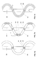
- FIG. 2 shows the flow conditions along a single vane.
- the central plane 35 is arranged essentially parallel to a flow direction 14 of an airflow, which has a straight leading edge 38 and a lobed trailing edge 39.
- the airflow 14 at the leading edge in a situation like that develops a flow profile as indicated schematically in the upper view with the arrows 14.
- the lobed structure 42 at the trailing edge 39 is progressively developing downstream the leading edge 38 to a wavy shape with lobes going into a first direction 30, which is transverse to the central plane 35, the lobe extending in that first direction 30 is designated with the reference numeral 28.
- Lobes extending into a second transverse direction 31, so in figure 1a in a downward direction, are designating with reference numeral 29.
- the lobes alternate in the two directions and wherever the lobes or rather the line/plane forming the trailing edge pass the central plane 35 there is a turning point 27.
- the lobed structure 42 is defined by the following parameters:
- Fig. 3 shows in a) and b) a swirler 43 with a plurality of vanes 22 from a downstream end of the swirler.
- the lobes on neighboring vanes 22 shown in a) are arranged in phase with each other, i.e. the lobes have the same periodicity.
- lobes 22 of neighboring vanes 22 cross their respective centerline at the same position in longitudinal direction, and at the same position in longitudinal direction the deflection of each body has the same absolute value.
- the lobes on neighboring vanes 22 shown in b) are arranged out of phase with each other, in particular the phases are shifted by 180°, i.e. lobes of both vanes 22 cross the center line at the same position in longitudinal direction, and at the same position in longitudinal direction the deflection of each body has the same absolute value but is in opposite direction.
- Lobes which are arranged out of phase, can lead to a further improved in mixing.
- Figure 3c) and 3d ) show examples of an annular combustors with burners 1 comprising swirlers 43 with lobed trailing edges on their vanes 22 from a downstream end.
- the burners 43 are distributed equally spaced on circle around the center axis of a gas turbine and discharge the combustible mixture of fuel and gas into an annular combustor.
- the each burner 1 comprises one swirler 43.
- five swirlers 43 are arranged in a circular pattern in each burner 1.
- the burners of figure 3c) and 3d ) can also be used in combination with a plurality of can combustors instead of in one annular combustor.
- FIG. 4a shows a perspective view of a section of a swirler 43 of the kind one used in Fig. 3a.
- Fig. 4a shows a perspective view of a section of a swirler 43 comprising two vanes 22 with lobes on the trailing edges, which are arranged between an inner limiting walls 44',and an outer limiting wall 44", which form an annular flow path with an inlet area 45 and an outlet area 46.
- the lobes on the vanes 22 are arranged in phase.
- the vanes 22 are configured to redirect the main flow, which enters the swirler 43 in the inlet flow direction 48 coaxially to the annular flow path to a flow direction, to impose a swirl on the flow, and resulting in an outlet flow direction 55, which has an angle relative to the inlet flow direction 48 and rotates around the axis of the swirler 43.
- the flat projection of the swirler 43 with lobes on the trailing edges of the vanes 22 is shown in Fig. 3b . It shows the height h of the vanes 22 as the distance in a direction perpendicular to the main flow direction between adjacent apexes of adjacent lobes, the first lobe angle ⁇ 1 which defines the displacement into the first direction of the lobe 28, and the second lobe angle ⁇ 2 , which defines the displacement of lobe 29 in the direction 31.
- the lobe angles ⁇ 1 and ⁇ 2 are relative to a tangential to the centerline of the lobe 22. Typically ⁇ 1 is identical to ⁇ 2 .
- the lobes either extend with a constant lobe angle in axial direction or start practically parallel to the main flow direction and the lobe angle is gradually increasing in flow direction.
- Fig. 3b shows the outlet angle ⁇ , by which the main flow is turned in the swirler 43 to impose a swirl on the flow.
- Fig. 5 shows a schematic perspective view of the vanes 22 in a swirler.
- the sidewalls and inlet are not shown.
- the vanes 22 have a straight leading edge 38, are twisted, and lobes are arranged in phase at the trailing edges 39.
- Fig. 6 shows a schematic side view of a burner 1 with two concentrically arranged swirlers 43. Air 48 and fuel 56 are supplied to the burner 1.
- the two swirlers 43 comprise vanes, which turn in opposite direction thereby imposing counter-rotating swirls on the air and fuel mixture leaving the swirlers 43, thus further improving the mixing in the burner.
- the lobes of vanes 22 of the inner and outer swirler 43 can be of different form, size and orientation.
- the vanes 22 on the inner swirler 43 can have lobes on neighboring vanes 22, which are arranged out of phase for improved mixing and to compensate for a smaller velocity component in circumferential direction while the vanes 22 on the outer swirler 43 can have lobes on neighboring vanes 22, which are arranged in phase to reduce the pressure trop or to allow a high axial velocity.
- Figure 7 shows views against the main flow onto the trailing edge of lobed vanes 22 with different nozzle arrangements according to the invention.
- Figure 7a shows an arrangement where first nozzles 51 for injection of liquid fuel, are enclosed by second nozzles 52 for injection of a gaseous fuel, which themselves are encloses by third nozzles 53 for injection of carrier air.
- the nozzles 51, 52, 53 are arranged concentrically at the trailing edge.
- Each nozzle arrangement is located where the lobed trailing edge crosses the center plane 35.
- Figure 7b shows an arrangement where second nozzles 52 for fuel gas injection are configured as a slit- like nozzle extending along the trailing edge each at each apex section of the lobes.
- first nozzles 51 for liquid fuel injection arranged at each location where the lobed trailing edge crosses the center plane 35. All the first and second nozzles 51, 52 are enclosed by third nozzles 53 for the injection of carrier air.
- Figure 7c shows an arrangement where a second nozzle 52 for fuel gas injection is configured as one slit- like nozzle extending along at least one lobe along the trailing edge.
- additional first nozzles 51 in the form of orifices are arranged in the second nozzles 52.
- Burner with lobed swirlers can be designed to operate with increased fuel flexibility without suffering on high NOx emissions or flashback.
- the mixing of the fuel and the oxidizer at the exit of the mixing zone is just sufficient to allow low NOx emissions (mixing quality) and avoid flashback (residence time), which may be caused by auto ignition of the fuel air mixture in the mixing zone.
- the present invention relates to burning of fuel air mixtures with a low ignition delay time. This is achieved by an integrated approach, which allows higher velocities of the main flow and in turn, a lower residence time of the fuel air mixture in the mixing zone.
- the challenge regarding the fuel injection is twofold with respect to the use of hydrogen rich fuels and fuel air mixtures with high temperatures:
- the conditions which one aspect of the presented invention wants to address are those where the reactivity as defined above is above 1 and the flames are auto igniting, the invention is however not limited to these conditions.
- the main goal of this invention is to evolve an improved burner configuration, wherein the latter two points are addressed, which however can be combined also with the upper three points.
- the injector is designed to perform
- r r is defined as the ratio of recirculated flow to swirl flow.
- r r is defined as the ratio of recirculated flow to swirl flow.
- a high recirculation rate leads to better combustion.
- the flame stability improves with the recirculation rate, i.e. combustion pulsations can be avoided or reduced with increasing recirculation rate.
- s n is defined as the ratio of swirl flow to total mass flow through the burner 1. Since a swirl flow can only be imposed with a pressure drop, the swirl number s n should be kept low for an optimized performance, i.e. power and efficiency of the gas turbine.
- Figure 8 schematically shows the recirculation rate r r as a function of the swirl number s n .
- the recirculation rate 57 is shown for a swirler 43 with flat vanes 22
- the recirculation rate 58 is shown for a swirler 43 with curved or twisted vanes 22
- the recirculation rate 59 is shown for a swirler 43 with curved or twisted vanes 22 and lobes 42.
- Figure 8 clearly indicates that a higher relative recirculation flow r r can be achieved at a given swirl number s n swirl therefore improving the combustion without increasing the burner and combustor pressure drop.
- the lobed swirler allows combustion at high hot gas temperatures with low emissions.
Abstract
Description
- The present invention relates to a lobed swirler as well as a burner for a combustion chamber of a gas turbine comprising such a device. In particular it relates to lobed swirlers for the introduction of at least one gaseous and/or liquid into a burner.
- Swirlers are needed for mixing devices in various technical applications. Optimization of swirler aims at reducing the energy required to obtain a specified degree of homogeneity. In continuous flow mixing the pressure drop over a mixing device is a measure for the required energy. Further, the time and space required to obtain the specified degree of homogeneity are important parameters when evaluating mixing devices or mixing elements. Swirlers are typically used for mixing of two continuous fluid streams.
- High volume flows of gas are for example mixed at the outlet of turbofan engines, where the hot exhaust gases of the core engine mix with relatively cold and slower bypass air. In order to reduce the sound emissions caused by these different flows lobe mixers were suggested for example in
US4401269 . - One specific application for mixing of continuous flow streams is the mixing of a fuel with an oxidizing fluid, for example air, in a burner for premixed combustion in a subsequent combustion chamber. In modern gas turbines good mixing of fuel and combustion air is a prerequisite for complete combustion with low emissions.
- In order to achieve a high efficiency, a high turbine inlet temperature is required in standard gas turbines. As a result, there arise high NOx emission levels and higher life cycle costs. These problems can be mitigated with a sequential combustion cycle, wherein the compressor delivers nearly double the pressure ratio of a conventional one. The main flow passes the first combustion chamber (e.g. using a burner of the general type as disclosed in
EP 1 257 809US 4,932,861 , also called EV combustor, where the EV stands for EnVironmental), wherein a part of the fuel is combusted. After expanding at the high-pressure turbine stage, the remaining fuel is added and combusted (e.g. using a burner of the type as disclosed inUS 5,431,018 orUS 5,626,017 or inUS 2002/0187448 , also called SEV combustor, where the S stands for sequential). Both combustors contain premixing burners, as low NOx emissions require high mixing quality of the fuel and the oxidizer. - Since the second combustor is fed by the expanded exhaust gas of the first combustor, the operating conditions allow self ignition (spontaneous ignition) of the fuel air mixture without additional energy being supplied to the mixture. To prevent ignition of the fuel air mixture in the mixing region, the residence time therein must not exceed the auto ignition delay time. This criterion ensures flame-free zones inside the burner. This criterion poses challenges in obtaining appropriate distribution of the fuel across the burner exit area. SEV-burners are currently only designed for operation on natural gas and oil. Therefore, the momentum flux of the fuel is adjusted relative to the momentum flux of the main flow so as to penetrate in to the vortices. This is done using air from the last compressor stage (high-pressure carrier air). The high-pressure carrier air is bypassing the high-pressure turbine. The subsequent mixing of the fuel and the oxidizer at the exit of the mixing zone is just sufficient to allow low NOx emissions (mixing quality) and avoid flashback (residence time), which may be caused by auto ignition of the fuel air mixture in the mixing zone.
- It is an object of the present invention to provide a highly effective swirler with a low pressure drop. As an application of such a swirler a burner comprising such a swirler is disclosed.
- First of all a swirler, which produces a mixture with a high homogeneity using only a minimum pressure drop, is proposed. Further, a burner with such a swirler is proposed. Such a burner is proposed for example to increase the gas turbine engine efficiency, to increase the fuel capability as well as to simplify the design.
- The proposed swirler comprises an annular housing with limiting walls having an inlet area, and an outlet area in a main flow direction. At least two vanes are arranged in the annular housing, each having a streamlined cross-sectional profile, which extends with a longitudinal direction perpendicularly or at an inclination to the main flow direction prevailing in the swirler. The leading edge area of each vane has a profile, which is oriented parallel to a main flow direction prevailing at the leading edge position, and wherein the profiles of the vanes turn from the main flow direction prevailing at the leading edge position to impose a swirl on the flow. The swirl is rotating around a center axis of the swirler. With reference to a central plane of the vanes the trailing edges are provided with at least two lobes in opposite transverse directions to improve the mixing at a low pressure drop.
- As a result a superimposed mixing device, which mixes due to the combined effect of the swirl and the vortices caused by the lobes, is obtained. The swirl leads to a mixing on large scale and the vortices mixes on a small scale, resulting in an overall homogeneous mixing. When applied to a burner the lobed swirler does not only lead to a good mixing at low pressure drop but also to a high recirculation flow in a subsequent combustor. A high recirculation flow leads to better, more stable combustion. Typically the flame stability improves with the recirculation flow, i.e. combustion pulsations can be avoided or reduced with increasing recirculation flow.
- Typically, between 4 and 20 vanes are used per swirler. In one embodiment between 10 and 15 vanes are used per swirler. To avoid Eigenfrequencies in flow downstream of the vanes an odd number of vanes is suggested in a further embodiment.
- The lobes alternatingly extend out of the central plane, i.e. in the transverse direction with respect to the central plane. The shape can for example be a sequence of semi-circles, sectors of circles, it can be in a sinus or sinusoidal form, it may also be in the form of a combination of sectors of circles or sinusoidal curves and adjunct straight sections, where the straight sections are asymptotic to the curves or sectors of circles. Further triangular, rectangular or similar periodic shapes are conceivable. Preferentially, all lobes are of essentially the same shape along the trailing edge. The lobes are arranged adjacent to each other so that they form an interconnected trailing edge line. The lobe angles should be chosen in such a way that flow separation is avoided. According to one embodiment lobe angles (α1, α2) are between 15° and 45°, preferably between 25° and 35° to avoid flow separation.
- According to a preferred embodiment the layout of the lobes is designed to assure a distribution of tangential velocity and axial velocity at the trailing edge of the blades that leads to a sinusoidal radial distribution of the exit angle, where the exit angle is the normalized ratio of the tangential velocity (in radial direction) to the axial velocity.
- Typically the distance in radial direction between to maxima in the exit angle is equal to the distance between two maxima in the deflection of lobes.
- According to a preferred embodiment, the trailing edge is provided with at least 3, preferably at least 4 lobes sequentially arranged one adjacent to the next along the trailing edge, and alternatingly lobing in the two opposite transverse directions.
- A further preferred embodiment is characterized in that the vane comprises an essentially straight leading edge. The leading edge may however also be rounded, bent or slightly twisted.
- According to a further preferred embodiment, the vane, in its upstream portion with respect to the main flow direction, has a maximum width. Downstream of this width W the width, i.e. the distance between the lateral sidewalls defining the vane, essentially continuously diminishes towards the trailing edge (the trailing edge either forming a sharp edge or rounded edge). The height, defined as the distance in the transverse direction of the apexes of adjacent lobes, is in this case preferentially at least half of the maximum width. According to one particular preferred embodiment, this height is approximately the same as the maximum width of the vane. According to another particular preferred embodiment, this height is approximately twice the maximum width of the vane. Generally speaking, preferentially the height is at least as large as the maximum width, preferably not more than three times as large as the maximum width.
- According to an embodiment the swirler's the vanes comprise an essentially straight leading edge.
- According to a further preferred embodiment, the transverse displacement of the vane forming the lobes is only at most in the downstream two thirds of the length 1 (measured along the main flow direction) of the vane. This means that the upstream portion the vane has an essentially symmetric shape with respect to the central plane. Downstream thereof the lobes are continuously and smoothly growing into each transverse direction forming a wavy shape of the sidewalls of the vane where the amplitude of this wavy shape is increasing the maximum value at the trailing edge.
- For swirlers, in which the lobes are in phase, the average distance between the central planes of two vanes is at least 0.5 times the height of the lobes, preferably at least 0.9 times the height of the lobes in order to optimize the flow pattern in the mixer.
- According to a further embodiment the traverse deflection from the central plane of two adjacent vanes, which form the lobes are inverted. For inverted lobes the average distance between the central planes of two vanes is at least 1.2 times the height of the lobes, preferably at least 1.2 times the height of the lobes in order to optimize the flow pattern in the mixer, and to allow mixing normal to the central planes of two vanes as well as in direction of the central planes of two neighboring vanes,
- In yet another embodiment, the transition from a planar leading edge region to the deflections is smooth with a surface curvature representing a function with a continuous first derivative.
- According to one embodiment the housing is extending with a central axis aligned with the main flow direction. The resulting swirler has inlet area and an outlet area, which are normal to the central axis to form an axial swirler with lobed vanes.
- According to another embodiment the lobe height and/ or the periodicity is a function of the radial distance of the lobe to the center axis of the swirler along the trailing edge of the vane. For example the lobe height and/ or the periodicity are proportional to the radial distance of the lobe to the center axis of the swirler along the trailing edge of the vane.
- Besides axial swirlers radial swirlers with lobed vanes are conceivable. According to one embodiment an annular housing is extending in radial direction with a central axis normal to the main flow direction and the inlet area and the outlet area are arranged concentric and to form a radial swirler.
- For use in applications with turbulent inflow to the swirler at least two vanes are provided with at least two lobes in opposite transverse directions at the leading edges of the vanes. In flow direction, the additional lobes in at the leading edge area typically extend up to about the onset of the trailing edge lobes. They have a flow conditioning effect on turbulent inflows and improve the mixing due to the downstream lobes.
- In one embodiment the traverse deflection from the central plane of two adjacent vanes, which form the lobes are in phase for a low pressure drop. For additionally improved mixing the traverse deflection from the central plane of two adjacent vanes, which form the lobes, is out of phase. Preferably phases are inverted, i.e. the phase angle is 180°.
- A specific objective of the invention is to provide a burner with improved mixing. This object is achieved by providing a burner with a swirler configured as injection device, wherein the swirler has at least one vane which is arranged in the burner with at least one nozzle for introducing the at least one fuel into the burner. The at least one vane has a streamlined cross-sectional profile h extends with a longitudinal direction perpendicularly or at an inclination to a main flow direction prevailing in the swirler. According to the invention, such a vane is formed such that with reference to a central plane of the vane the trailing edge is provided with at least two lobes in opposite transverse directions.
- In other words the trailing edge does not form a straight line but a wavy or sinusoidal line, where this line oscillates around the central plane. The present invention involves injection of fuel from the lobed vane. Typically the fuel is injected at the trailing edge of the lobed injectors. The fuel injection is preferably along the axial direction, which eliminates the need for high-pressure carrier air.
- The invention allows fuel-air mixing with low momentum flux ratios being possible. An inline fuel injection system includes number of lobed vanes staggered to each other.
- The burner can be used for fuel-air mixing as well as mixing of fuel with any kind of gas used in closed or semi- closed gas turbines or with combustion gases of a first combustion stage.
- These burners can be used for gas turbines comprising one compressor, one combustor and one turbine as well as for gas turbines with one or multiple compressors, at least two combustors and at least two turbines. They can for example be used as premix burners in a gas turbine with one combustor or also be used in a reheat combustor for a secondary combustion chamber of a gas turbine with sequential combustion having a first and a second combustion chamber, with an injection device for the introduction of at least one gaseous and/or liquid fuel into the burner.
- The burner can comprise of one swirler or a plurality of swirlers. A burner with one swirler typically has a circular cross section. A burner comprising a plurality of swirlers can have any cross- section but is typically circular or rectangular. Typically a plurality of burners is arranged coaxially around the axis of a gas turbine. The burner cross section is defined by a limiting wall, which for example forms a can like burner.
- The invention allows reduced pressure losses by an innovative injector design. The advantages are as follows:
- ● Increased GT efficiency
- o Lobes can be shaped to produce appropriate flow structures. Intense shear of the vortices helps in rapid mixing and avoidance of low velocity pockets. An aerodynamically favored injection and mixing system reduces the pressure drop even further. Due to only having one device (injector) rather than the separate elements i) large-scale mixing device at the entrance of the burner, ii) vortex generators on the injector, and iii) injector pressure is saved. The savings can be utilized in order to increase the main flow velocity, which is beneficial if it comes to fuel air mixtures with high reactivity or can be utilized to increase the gas turbine performance.
- ● The fuel may be injected in-line right at the location where the vortices are generated. The design of the cooling air passage can be simplified, as the fuel does not require momentum from high-pressure carrier air anymore.
- One of the gists of the invention here is to merge the vortex generation aspect and the fuel injection device as conventionally used according to the state-of-the-art as a separate elements (separate structural vortex generator element upstream of separate fuel injection device) into one single combined vortex generation and fuel injection device. By doing this, mixing of fuels with oxidation air and vortex generation take place in very close spatial vicinity and very efficiently, such that more rapid mixing is possible and the length of the mixing zone can be reduced. It is even possible in some cases, by corresponding design and orientation of the body in the oxidizing air path, to omit the flow conditioning elements (flow straightener, guide vanes) as the body may also take over the flow conditioning. All this is possible without severe pressure drop along the injection device such that the overall efficiency of the process can be maintained or improved.
- Typically, in particular for gas turbine applications, the vane has a height H along its longitudinal axis (perpendicular to the main flow) in the range of 20-200 mm. In particular under the circumstances, the lobe periodicity ("wavelength") λ is preferentially in the range of 10-100mm, preferably in the range of 20-60mm. This means that along the trailing edge of a vane there are located for example six alternating lobes, three in each transverse direction.
- According to yet another preferred embodiment, at least two, preferably at least three, possible even four, five ore more fuel nozzles are located at the trailing edge and distributed (preferentially in equidistant manner) along the trailing edge.
- According to yet another preferred embodiment, the fuel nozzles are located essentially on the central plane of the vane (so typically not in the lobed portions of the trailing edge). In this case, a fuel nozzle is preferably located at each position or every second position along the trailing edge, where the lobed trailing edge crosses the central plane.
- According to yet another embodiment, the fuel nozzles are located essentially at the apexes of lobes, wherein preferably a fuel nozzle is located at each apex or every second apex along the trailing edge.
- According to another embodiment the burner at least one injection device with at least one nozzle for introducing at least one fuel into the burner upstream of the vanes and/ or at least one nozzle for introducing at least one fuel into the burner is provided at the inner limiting wall and/or the outer limiting wall of the burner.
- Typically, at least the nozzle injects fuel (liquid or gas) and/or carrier gas parallel to the main flow direction. At least one nozzle may however also inject fuel and/or carrier gas at an inclination angle of normally not more than 30° with respect to the main flow direction. Preferably, the vane extends across the entire flow cross section between opposite walls of the burner.
- According to a preferred embodiment, the vane is provided with cooling elements, wherein preferably these cooling elements are given by internal circulation of cooling medium along the sidewalls of the vane (i.e. by providing a double wall structure) and/or by film cooling holes, preferably located near the trailing edge, and wherein most preferably the cooling elements are fed with air from the carrier gas feed also used for the fuel injection.
- A plurality of separate outlet orifices of a plurality of nozzles can be arranged next to one another and arranged at the trailing edge.
- At least one slit-shaped outlet orifice can be, in the sense of a nozzle, arranged at the trailing edge. A split-shaped or elongated slot nozzle is typically arranged to extend along the trailing edge of the vane.
- The nozzles can comprise multiple outlet orifices for different fuel types and carrier air. In one embodiment a first nozzle for injection of liquid fuel or gas fuel, and a second nozzle for injection of carrier air, which encloses the first nozzle, are arranged at the trailing edge. In another embodiment a first nozzle for injection of liquid fuel, a second nozzle for injection of a gaseous fuel, which encloses the first nozzle, and a third nozzle for injection of carrier air, which encloses the first nozzle, and the second nozzle, are arranged at the trailing edge.
- Besides an improved burner comprising the swirler a method for operation of such a burner is an objective of the invention. Depending on the operating conditions, and load point of a gas turbine, the fuel flow injected trough a burner varies in a wide range. A simple operation where the flow is equally distributed to all burner nozzles and the flow through each nozzle is proportional to the total flow can lead to very small flow velocities at individual nozzles impairing the injection quality and penetration depth f the fuel into the air flow.
- According to one embodiment of the operating method the number of fuel injection nozzles trough which fuel is injected is determined as function of the total injected fuel flow in order to assure a minimum flow in the operative nozzles.
- In another embodiment the fuel is injected through every second fuel nozzle of a vane at low fuel flow rates. Alternatively the fuel is only injected through the fuel nozzles of every second or third vane of the burner. Further, the combination of both methods to reduce fuel injection is suggested: For low fuel mass flows the fuel is injected trough every second or third fuel nozzle of a vane and only through the fuel nozzles of every second or third vane of the burner is proposed. At an increased mass flow the number of vanes used for fuel injection and then the number of nozzles used for fuel injection per vane can be increased. Alternatively, at an increased mass flow the number of nozzles used for fuel injection per vane can be increased and then the number of vanes used for fuel injection and can be increased. Activation and deactivation of nozzles can for example be determined based on corresponding threshold fuel flows.
- Furthermore the present invention relates to the use of a burner as defined above for the combustion under high reactivity conditions, preferably for the combustion at high burner inlet temperatures and/or for the combustion of MBtu fuel, normally with a calorific value of 5000-20,000 kJ/kg, preferably 7000-17,000 kJ/kg, more preferably 10,000-15,000 kJ/kg, most preferably such a fuel comprising hydrogen gas.
- Further embodiments of the invention are laid down in the dependent claims.
- Preferred embodiments of the invention are described in the following with reference to the drawings, which are for the purpose of illustrating the present preferred embodiments of the invention and not for the purpose of limiting the same. In the drawings,
- Fig. 1
- shows a schematic perspective view onto a conventional swirler with vanes having straight trailing edges;
- Fig. 2
- shows in a) a schematic perspective view onto a lobed vane and the flow paths generated on both sides and at the trailing edge thereof, and in b) a side elevation view thereof;
- Fig. 3
- shows in a) a swirler with vanes from a downstream end with lobes on neighboring vanes arranged in phase with each other, and in b) out of phase and further shows in c) an example of an annular combustor with burners comprising one swirler per burner as well as in d) an example of an annular combustor with a burners comprising five swirlers per burner;
- Fig. 4
- shows in a) a schematic perspective view of section of a swirler comprising vanes where lobes on neighboring vanes are arranged in phase and in b) a section of a flat projection of the swirler.
- Fig. 5
- a schematic perspective view of a swirler with twisted vanes and lobes at the trailing edge;
- Fig. 6
- shows a schematic side view of a burner with two concentrically arranged swirlers;
- Fig. 7
- shows views against the main flow onto the trailing edge of lobed vanes with different nozzle arrangements according to the invention;
- Fig. 8
- schematically shows the relative recirculation flow as a function of the swirl number for different swirler types.
-
Fig. 1 shows in a schematic perspective view onto aconventional swirler 43. Theswirler 43 comprises an annular housing with an inner limiting wall 44', an outer limitingwall 44", aninlet area 45, and anoutlet area 46.Vanes 22 are arranged between the inner limiting wall 44' and outer limitingwall 44". The leading edge area of eachvane 22 has a profile, which is oriented parallel to theinlet flow direction 48. In the example shown the inflow is coaxial to thelongitudinal axis 47 of theswirler 43. The profiles of thevanes 22 turn from themain flow direction 48 to impose a swirl on the flow, and resulting in anoutlet flow direction 55, which has an angle relative to theinlet flow direction 48. The main flow is coaxial to the annular swirler. The outlet flow is rotating around the axis of the swirler. - The lobed mixing concept is described with reference to
figure 2. Figure 2 shows the flow conditions along a single vane. Thecentral plane 35 is arranged essentially parallel to aflow direction 14 of an airflow, which has a straightleading edge 38 and alobed trailing edge 39. Theairflow 14 at the leading edge in a situation like that develops a flow profile as indicated schematically in the upper view with thearrows 14. - The
lobed structure 42 at the trailingedge 39 is progressively developing downstream the leadingedge 38 to a wavy shape with lobes going into afirst direction 30, which is transverse to thecentral plane 35, the lobe extending in thatfirst direction 30 is designated with thereference numeral 28. Lobes extending into a secondtransverse direction 31, so infigure 1a in a downward direction, are designating withreference numeral 29. The lobes alternate in the two directions and wherever the lobes or rather the line/plane forming the trailing edge pass thecentral plane 35 there is a turning point 27. - As one can see from the arrows indicated in
figure 1a , the airflow flowing in the channel-like structures on the upper face and the airflows in the channels on the lower face intermingle and start to generate vortexes downstream of the trailingedge 39 leading to an intensive mixing as indicated withreference numeral 41.Theses vortices 41 are useable for the injection of fuels/air as will be discussed further below. - The
lobed structure 42 is defined by the following parameters: - ● the periodicity λ gives the width of one period of lobes in a direction perpendicular to the
main flow direction 14; - ● the height h is the distance in a direction perpendicular to the
main flow direction 14, so along thedirections figure 1b - ● the first lobe angle α1 (also called elevation angle) which defines the displacement into the first direction of the
lobe 28, and -
Fig. 3 shows in a) and b) aswirler 43 with a plurality ofvanes 22 from a downstream end of the swirler. The lobes on neighboringvanes 22 shown in a) are arranged in phase with each other, i.e. the lobes have the same periodicity. Thus,lobes 22 of neighboringvanes 22 cross their respective centerline at the same position in longitudinal direction, and at the same position in longitudinal direction the deflection of each body has the same absolute value. - The lobes on neighboring
vanes 22 shown in b) are arranged out of phase with each other, in particular the phases are shifted by 180°, i.e. lobes of bothvanes 22 cross the center line at the same position in longitudinal direction, and at the same position in longitudinal direction the deflection of each body has the same absolute value but is in opposite direction. - Lobes, which are arranged out of phase, can lead to a further improved in mixing.
-
Figure 3c) and 3d ) show examples of an annular combustors withburners 1 comprisingswirlers 43 with lobed trailing edges on theirvanes 22 from a downstream end. Theburners 43 are distributed equally spaced on circle around the center axis of a gas turbine and discharge the combustible mixture of fuel and gas into an annular combustor. In the example shown infigure 3c ) the eachburner 1 comprises oneswirler 43. In the example shown infigure 3d ) fiveswirlers 43 are arranged in a circular pattern in eachburner 1. - The burners of
figure 3c) and 3d ) can also be used in combination with a plurality of can combustors instead of in one annular combustor. - A perspective view of a section of a
swirler 43 of the kind one used inFig. 3a is shown inFig. 4a. Fig. 4a shows a perspective view of a section of aswirler 43 comprising twovanes 22 with lobes on the trailing edges, which are arranged between an inner limiting walls 44',and an outer limitingwall 44", which form an annular flow path with aninlet area 45 and anoutlet area 46. The lobes on thevanes 22 are arranged in phase. - The
vanes 22 are configured to redirect the main flow, which enters theswirler 43 in theinlet flow direction 48 coaxially to the annular flow path to a flow direction, to impose a swirl on the flow, and resulting in anoutlet flow direction 55, which has an angle relative to theinlet flow direction 48 and rotates around the axis of theswirler 43. - The flat projection of the
swirler 43 with lobes on the trailing edges of thevanes 22 is shown inFig. 3b . It shows the height h of thevanes 22 as the distance in a direction perpendicular to the main flow direction between adjacent apexes of adjacent lobes, the first lobe angle α1 which defines the displacement into the first direction of thelobe 28, and the second lobe angle α2, which defines the displacement oflobe 29 in thedirection 31. The lobe angles α1 and α2 are relative to a tangential to the centerline of thelobe 22. Typically α1 is identical to α2. The lobes either extend with a constant lobe angle in axial direction or start practically parallel to the main flow direction and the lobe angle is gradually increasing in flow direction. - Further,
Fig. 3b shows the outlet angle β, by which the main flow is turned in theswirler 43 to impose a swirl on the flow. -
Fig. 5 shows a schematic perspective view of thevanes 22 in a swirler. The sidewalls and inlet are not shown. In this example thevanes 22 have a straightleading edge 38, are twisted, and lobes are arranged in phase at the trailingedges 39. -
Fig. 6 shows a schematic side view of aburner 1 with two concentrically arrangedswirlers 43.Air 48 andfuel 56 are supplied to theburner 1. The twoswirlers 43 comprise vanes, which turn in opposite direction thereby imposing counter-rotating swirls on the air and fuel mixture leaving theswirlers 43, thus further improving the mixing in the burner. The lobes ofvanes 22 of the inner andouter swirler 43 can be of different form, size and orientation. For example thevanes 22 on theinner swirler 43 can have lobes on neighboringvanes 22, which are arranged out of phase for improved mixing and to compensate for a smaller velocity component in circumferential direction while thevanes 22 on theouter swirler 43 can have lobes on neighboringvanes 22, which are arranged in phase to reduce the pressure trop or to allow a high axial velocity. -
Figure 7 shows views against the main flow onto the trailing edge oflobed vanes 22 with different nozzle arrangements according to the invention.Figure 7a shows an arrangement wherefirst nozzles 51 for injection of liquid fuel, are enclosed bysecond nozzles 52 for injection of a gaseous fuel, which themselves are encloses bythird nozzles 53 for injection of carrier air. Thenozzles center plane 35.Figure 7b shows an arrangement wheresecond nozzles 52 for fuel gas injection are configured as a slit- like nozzle extending along the trailing edge each at each apex section of the lobes. Additionallyfirst nozzles 51 for liquid fuel injection arranged at each location where the lobed trailing edge crosses thecenter plane 35. All the first andsecond nozzles third nozzles 53 for the injection of carrier air.Figure 7c shows an arrangement where asecond nozzle 52 for fuel gas injection is configured as one slit- like nozzle extending along at least one lobe along the trailing edge. For liquid fuel injection additionalfirst nozzles 51 in the form of orifices are arranged in thesecond nozzles 52. - Burner with lobed swirlers can be designed to operate with increased fuel flexibility without suffering on high NOx emissions or flashback.
- The key advantages can be summarized as follows:
- ● Higher burner velocities to accommodate highly reactive fuels
- ● Lower burner pressure drop for similar mixing levels achieved with current designs
- The mixing of the fuel and the oxidizer at the exit of the mixing zone is just sufficient to allow low NOx emissions (mixing quality) and avoid flashback (residence time), which may be caused by auto ignition of the fuel air mixture in the mixing zone.
- According to one embodiment the present invention relates to burning of fuel air mixtures with a low ignition delay time. This is achieved by an integrated approach, which allows higher velocities of the main flow and in turn, a lower residence time of the fuel air mixture in the mixing zone. The challenge regarding the fuel injection is twofold with respect to the use of hydrogen rich fuels and fuel air mixtures with high temperatures:
- ● Hydrogen rich fuels may change the penetration behavior of the fuel jets. The penetration is determined by the cross section areas of the burner and the fuel injection holes, respectively.
- ● The second problem is that depending on the type of fuel or the temperature of the fuel air mixture, the reactivity, which can be defined as tign,ref/tign, i.e. as the ratio of the ignition time of reference natural gas to the actual ignition time of the fuel air mixture changes.
- The conditions which one aspect of the presented invention wants to address are those where the reactivity as defined above is above 1 and the flames are auto igniting, the invention is however not limited to these conditions.
- For each temperature and mixture composition the laminar flame speed and the ignition delay time change. As a result, hardware configurations must be provided offering a suitable operation window. For each hardware configuration, the upper limit regarding the fuel air reactivity is given by the flashback margin.
- In any burner the flashback is increased, as the residence time in the mixing zone exceeds the ignition delay time of the fuel air. Mitigation can be achieved in several different ways:
- ● The inclination angle of the fuel can be adjusted to decrease the residence time of the fuel. Herein, various possibilities regarding the design may be considered, e.g. inline fuel injection, i.e. essentially parallel to the oxidizing airflow, a conical lance shape or a horny lance design.
- ● The reactivity can be slowed down by diluting the fuel air mixture with nitrogen or steam, respectively.
- ● De-rating of the first stage can lead to less aggressive inlet conditions for the second combustor in a gas turbine with sequential combustion in case of highly reactive fuels. In turn, the efficiency of the overall gas turbine may decrease.
- ● The length of the mixing zone can be kept constant, if in turn the main flow velocity is increased. However, then normally a penalty on the pressure drop must be taken.
- ● By implementing more rapid mixing of the fuel and the oxidizer, the length of the mixing zone can be reduced while maintaining the main flow velocity.
- The main goal of this invention is to evolve an improved burner configuration, wherein the latter two points are addressed, which however can be combined also with the upper three points.
- In order to allow capability for highly reactive fuels, the injector is designed to perform
- ● flow conditioning (at least partial),
- ● injection and
- ● mixing
- One measure to judge the performance of a burner is the relative recirculation flow rr in a combustion chamber, where rr is defined as the ratio of recirculated flow to swirl flow. Typically a high recirculation rate leads to better combustion. Typically the flame stability improves with the recirculation rate, i.e. combustion pulsations can be avoided or reduced with increasing recirculation rate. However, to achieve a high relative recirculation flow rr a high swirl number sn, is required, where sn is defined as the ratio of swirl flow to total mass flow through the
burner 1. Since a swirl flow can only be imposed with a pressure drop, the swirl number sn should be kept low for an optimized performance, i.e. power and efficiency of the gas turbine. -
Figure 8 schematically shows the recirculation rate rr as a function of the swirl number sn. Therecirculation rate 57 is shown for aswirler 43 withflat vanes 22, therecirculation rate 58 is shown for aswirler 43 with curved ortwisted vanes 22, and therecirculation rate 59 is shown for aswirler 43 with curved ortwisted vanes 22 andlobes 42.Figure 8 clearly indicates that a higher relative recirculation flow rr can be achieved at a given swirl number sn swirl therefore improving the combustion without increasing the burner and combustor pressure drop. Thus the lobed swirler allows combustion at high hot gas temperatures with low emissions. - Several embodiments to the lobed fuel injection system are listed below:
- Embodiment 1:
Staggering of lobes to eliminate vortex-vortex interactions. The vortex-vortex interactions result in not effectively mixing the fuel air streams. - Embodiment 2:
Careful placement and location of fuel injection on the lobes: Fuel jets can be placed in the areas of high shear regions in order to best utilize the turbulent dissipation for mixing. - Embodiment 3:
Inclined fuel injection in the lobes: This allows fuel to be injected in to the vortex cores. - Embodiment 4:
Number of vanes and/ or lobes inside the burner: The vanes and/or lobes can be varied to decide on the strength of the vortices. - Embodiment 5:
Fuel staging in the lobed fuel injectors to control emissions and pulsations. - The advantages of lobed injectors when compared to existing concepts can be summarized as follows:
- ● Better streamlining of hot gas flows to produce strong vortices for rapid mixing and low-pressure drops.
- ● The high speed shearing of fuel mixture can be utilized to control combustor pulsations and flame characteristics.
- ● The lobed flute injector is flexible offering several design variations.
- ● Rapid shear of fuel and air due to lobed structures results in enhanced mixing delivered with shorter burner mixing lengths.
-
- 1
- burner
- 2
- mixing space, mixing zone
- 3
- burner wall
- 4
- combustion space
- 5
- outlet side, burner exit
- 6
- inlet side
- 7
- injection device, fuel lance
- 8
- main flow from high-pressure turbine
- 9
- flow conditioning, turbine outlet guide vanes
- 10
- vortex generators
- 11
- fuel mass fraction contour at burner exit 5
- 12
- combustion chamber wall
- 13
- transition between 3 and 12
- 14
- flow of oxidizing medium
- 15
- fuel nozzle
- 16
- foot of 7
- 17
- shaft of 7
- 18
- converging portion of 3
- 19
- reduced burner cross-sectional area
- 20
- reduction in cross section
- 21
- entrance section of 3
- 22
- vane
- 23
- lobed blade
- 24
- trailing edge of 22, 23
- 25
- leading edge of 22, 23
- 26
- injection direction
- 27
- turning point
- 28
- lobe in
first direction 30 - 29
- lobe in
second direction 31 - 30
- first transverse direction
- 31
- second transverse direction
- 32
- apex of 28,29
- 33
- lateral surface of 22
- 34
- ejection direction of fuel/carrier gas mixture
- 35
- central plane of 22/23
- 38
- leading edge of 24
- 39
- trailing edge of 23
- 40
- flow profile
- 41
- vortex
- 42
- lobes
- 43
- swirler
- 44
- limiting walls
- 44'
- inner limiting wall
- 44"
- outer limiting wall
- 45
- inlet area
- 46
- outlet area
- 47
- longitudinal axis of 43
- 48
- inlet flow direction
- 49
- longitudinal axis of 22
- 50
- central element
- 51
- first nozzle
- 52
- second nozzle
- 53
- third nozzle
- 54
- slot nozzle
- 55
- outlet flow direction
- 56
- fuel
- 57
- function for flat vanes
- 58
- function for curved vanes
- 59
- function for lobed vanes
- λ
- periodicity of 42
- h
- height of 42
- α1
- first lobe angle
- α2
- second lobe angle
- β
- inlet angle
- 1
- length of 22
- H
- height of 22
- w
- width at trailing edge
- W
- maximum width of 22
- rr
- recirculation rate
- sn
- swirl number
Claims (19)
- Swirler (43) comprising an annular housing with limiting walls (44) having an inlet area (45), and an outlet area (46) in the main flow direction, at least two vanes (22), which are arranged in the annular housing, each having a streamlined cross-sectional profile (48), which extends with a longitudinal direction (49) perpendicularly or at an inclination to a main flow direction (14) prevailing in the swirler (43), wherein the leading edge area of each vane (22) has a profile, which is oriented parallel to a main flow direction prevailing at the leading edge position, and wherein the profiles of the vanes (22) turn from the main flow direction prevailing at the leading edge position to impose a swirl on the flow, characterized in that, with reference to a central plane (35) of the vanes (22) the trailing edges (24) are provided with at least two lobes (28, 29) in opposite transverse directions (30, 31).
- Swirler (43) according to claim 1, characterized in that the transverse displacement of the vane forming the lobes (28, 29) is only at most in the downstream two thirds of the length (1) of the vane (22), preferably only in the downstream half of the length (1) of the vane (22).
- Swirler (43) according to any of the preceding claims, characterized in that the transverse displacement of the vane, which is forming the lobes (28, 29), has a sinusoidal form or a semi-circular form or a triangular form or a rectangular from.
- Swirler (43) according to any of the preceding claims, characterized in that the traverse deflection from the central plane of two adjacent vanes (22), which form the lobes (28, 29), are inverted, and in that the transition from a planar leading edge region to the deflections is smooth with a surface curvature representing a function with a continuous first derivative.
- Swirler (43) according to any of the preceding claims, characterized in that the average distance between the central planes (35) of two vanes (22) is at least 1.2 times the height (h) of the lobes (42), preferably at least 1.5 times the height (h) of the lobes (42).
- Swirler (43) according to any of the preceding claims, characterized in (that the annular housing is extending with a central axis aligned with the main flow direction having inlet area (45) and an outlet area (46) normal to the central axis to form an axial swirler.
- Swirler (43) according to any of the preceding claims, characterized in that the lobe height (h) and/ or the periodicity (λ) is a function of the radial distance of the lobe to the center axis of the swirler along the trailing edge (24) of the vane (22) and/ or proportional to the radial distance of the lobe to the center axis of the swirler along the trailing edge (24) of the vane (22).
- Swirler (43) according to any of the claims 1 to 5, characterized in that the inlet area (45) and the outlet area (46) are concentric and in that the annular housing is extending with a central axis normal to the main flow direction to form a radial swirler.
- Swirler (43) according to any of the preceding claims, characterized in that the traverse deflection from the central plane of two adjacent vanes (22), which form the lobes (28, 29), are in phase or are inverted.
- Burner (1) for a combustion chamber of a gas turbine comprising a swirler (43) according to any of the preceding claims, characterized in that at least one of the vanes (22) is configured as an injection device with at least one nozzle (15) for introducing at least one fuel into the burner (1) and/ or that at least one injection device with at least one nozzle (15) for introducing at least one fuel into the burner (1) is provided upstream of the vanes (22) and/ or at least one nozzle (15) for introducing at least one fuel into the burner (1) is provided at the inner limiting wall (44') and/or the outer limiting wall (44").
- Burner (1) according to claim 10, characterized in that at least one fuel nozzles (15) is located at or in the trailing edge (24) of at least one of the vanes.
- Burner (1) according to claim 11, characterized in that at least two fuel nozzles (15) which are located at the trailing edge (24) of at least one of the vanes are located essentially at the apexes (32) of a lobes (28, 29), wherein preferably at each apex (32) or at every second apex (32) along the trailing edge (24) there is located a fuel nozzle (15), and/or wherein at least one fuel nozzles (15) is located essentially on the central plane (35) of the vane (22), wherein preferably at each position, where the lobed trailing edge (24) crosses the central plane (35), there is located a fuel nozzle (15).
- Burner (1) according to claim 11, characterized in that at least two fuel nozzles (15) are located at the trailing edge (24) of at least one of the vanes (22) and distributed along the trailing edge (24) and wherein the fuel nozzles (15) are located essentially at the apexes (32) of a lobes (28, 29), wherein preferably at each apex (32) or at every second apex (32) along the trailing edge (24) there is located a fuel nozzle (15).
- Burner (1) according any of the claims 10 to 12, characterized in that at least two fuel nozzles (15) are located at the trailing edge (24) of at least one of the vanes (22) and distributed along the trailing edge (24), wherein at least at one position, where the lobed trailing edge (24) crosses the central plane (35), there is located a fuel nozzle (15) for injection of a liquid fuel, and wherein at least one fuel nozzles (15) for injection of a gaseous fuel is located essentially at the turning points (27) between two lobes (28, 29).
- Burner (1) according to any of the claims 10 to 13, characterized in that the body (22) is provided with cooling elements, wherein preferably these cooling elements are given by internal circulation of cooling medium along the sidewalls of the body (22) and/or by film cooling holes, preferably located near the trailing edge (24), and wherein most preferably the cooling elements are fed with air from the carrier gas feed also used for the fuel injection.
- Burner (1) according to any of the claims 10 to 14, characterized in that the fuel nozzles (15) are circular and/or are elongated slot nozzles (54) extending along the trailing edge of the vane (22) and/or comprise a first nozzle for injection of liquid fuel (51), and/or a second nozzle (52) for injection of a gaseous fuel and a third nozzle (53) for injection of carrier air, which encloses the first nozzle (51) and/or the second nozzle (52).
- Method for operating a burner (1) according to any of the claims 10 to 15, characterized in that the number of fuel injection nozzles trough which fuel is injected is determined as function of the total injected fuel flow.
- Method for operating a burner (1) according to claim 16, characterized in that below threshold fuel flows fuel is only injected trough every second or third fuel nozzle (15) of a vane (22) and/or that fuel is only injected through the fuel nozzles of every second or third vane (22) of the burner (1).
- Method for operating a burner (1) according to any of the claims 10 to 17, characterized in that high reactivity fuel is injected through the trailing edge of the vanes (22) and that low reactivity fuel is injected through an injection device for introducing at least one fuel into the burner (1), which is provided upstream of the vanes (22) and/ or at least one nozzle (15) for introducing at least one fuel into the burner (1), which is provided at the inner limiting wall (44') and/or the outer limiting wall (44") and/or through an injection device for introducing at least one fuel into the burner (1), which is provided at the surfaces of the vanes (22) upstream of the trailing edge (24).
Applications Claiming Priority (1)
| Application Number | Priority Date | Filing Date | Title |
|---|---|---|---|
| CH7942011 | 2011-05-11 |
Publications (2)
| Publication Number | Publication Date |
|---|---|
| EP2522911A1 true EP2522911A1 (en) | 2012-11-14 |
| EP2522911B1 EP2522911B1 (en) | 2019-07-24 |
Family
ID=46027859
Family Applications (1)
| Application Number | Title | Priority Date | Filing Date |
|---|---|---|---|
| EP12167608.4A Active EP2522911B1 (en) | 2011-05-11 | 2012-05-11 | Burner with a lobed swirler |
Country Status (4)
| Country | Link |
|---|---|
| US (1) | US9347663B2 (en) |
| EP (1) | EP2522911B1 (en) |
| JP (1) | JP5746091B2 (en) |
| RU (1) | RU2550370C2 (en) |
Cited By (8)
| Publication number | Priority date | Publication date | Assignee | Title |
|---|---|---|---|---|
| DE102012221342A1 (en) * | 2012-11-22 | 2014-05-22 | Friedrich Boysen Gmbh & Co. Kg | Flow guide device for distributing gas flow i.e. effluent stream, in e.g. metering pump, of motor car, has two face portions arranged in direction of flow of gas and curved along connecting line in connection |
| EP2796788A1 (en) | 2013-04-24 | 2014-10-29 | Alstom Technology Ltd | Swirl generator |
| CN107906514A (en) * | 2017-12-04 | 2018-04-13 | 安德森热能科技(苏州)有限责任公司 | A kind of Flat flame low NO |
| EP3330613A1 (en) | 2016-11-30 | 2018-06-06 | Ansaldo Energia Switzerland AG | Vortex generating device |
| EP3330614A1 (en) | 2016-11-30 | 2018-06-06 | Ansaldo Energia Switzerland AG | Vortex generating device |
| CN111828959A (en) * | 2020-07-23 | 2020-10-27 | 郑州轻工业大学 | Coal powder burner with adjustable shade and swirl vanes |
| WO2022119477A1 (en) * | 2020-12-01 | 2022-06-09 | Общество с ограниченной ответственностью "Биопрактика" (ООО "Биопрактика") | Static mixer for breaking down gas bubbles in a gas-liquid mixture |
| CN115264531A (en) * | 2022-06-30 | 2022-11-01 | 哈尔滨工程大学 | Split type lobe swirl vane and swirler suitable for gaseous fuel |
Families Citing this family (50)
| Publication number | Priority date | Publication date | Assignee | Title |
|---|---|---|---|---|
| RU2570989C2 (en) | 2012-07-10 | 2015-12-20 | Альстом Текнолоджи Лтд | Gas turbine combustion chamber axial swirler |
| RU2633475C2 (en) * | 2012-08-06 | 2017-10-12 | Сименс Акциенгезелльшафт | Local improvement of air and fuel mixing in burners supplied with swirlers with blade ends crossed at outer area |
| EP2837883B1 (en) * | 2013-08-16 | 2018-04-04 | Ansaldo Energia Switzerland AG | Premixed can annular combustor with mixing lobes for the second stage of a sequential gas turbine |
| US9528704B2 (en) | 2014-02-21 | 2016-12-27 | General Electric Company | Combustor cap having non-round outlets for mixing tubes |
| US9528702B2 (en) | 2014-02-21 | 2016-12-27 | General Electric Company | System having a combustor cap |
| KR101895137B1 (en) * | 2014-03-11 | 2018-09-04 | 미츠비시 히타치 파워 시스템즈 가부시키가이샤 | Combustion burner for boiler |
| US20150323185A1 (en) | 2014-05-07 | 2015-11-12 | General Electric Compamy | Turbine engine and method of assembling thereof |
| EP2966350B1 (en) | 2014-07-10 | 2018-06-13 | Ansaldo Energia Switzerland AG | Axial swirler |
| US10167883B2 (en) * | 2014-09-29 | 2019-01-01 | Luxnara Yaovaphankul | Apparatus for creating a swirling flow of fluid |
| EP3023696B1 (en) * | 2014-11-20 | 2019-08-28 | Ansaldo Energia Switzerland AG | Lobe lance for a gas turbine combustor |
| EP3026344B1 (en) * | 2014-11-26 | 2019-05-22 | Ansaldo Energia Switzerland AG | Burner of a gas turbine |
| EP3056819B1 (en) * | 2015-02-11 | 2020-04-01 | Ansaldo Energia Switzerland AG | Fuel injection device for a gas turbine |
| EP3076080B1 (en) * | 2015-03-30 | 2020-06-10 | Ansaldo Energia Switzerland AG | Fuel injector device |
| EP3076084B1 (en) * | 2015-03-30 | 2021-04-28 | Ansaldo Energia Switzerland AG | Fuel injector device |
| EP3147569A1 (en) | 2015-09-28 | 2017-03-29 | General Electric Technology GmbH | Vortex generator, and fuel injection system of a gas turbine with such vortex generator |
| CN105757716B (en) * | 2016-02-22 | 2019-04-30 | 中国科学院工程热物理研究所 | A kind of nozzle, nozzle array and burner for premixed combustion |
| US10502425B2 (en) * | 2016-06-03 | 2019-12-10 | General Electric Company | Contoured shroud swirling pre-mix fuel injector assembly |
| US10197279B2 (en) | 2016-06-22 | 2019-02-05 | General Electric Company | Combustor assembly for a turbine engine |
| US11022313B2 (en) | 2016-06-22 | 2021-06-01 | General Electric Company | Combustor assembly for a turbine engine |
| US10337738B2 (en) | 2016-06-22 | 2019-07-02 | General Electric Company | Combustor assembly for a turbine engine |
| US10598375B2 (en) * | 2016-11-01 | 2020-03-24 | Honeywell International Inc. | Asymmetrical and offset flare tip for flare burners |
| US10393382B2 (en) | 2016-11-04 | 2019-08-27 | General Electric Company | Multi-point injection mini mixing fuel nozzle assembly |
| US10352569B2 (en) | 2016-11-04 | 2019-07-16 | General Electric Company | Multi-point centerbody injector mini mixing fuel nozzle assembly |
| US10465909B2 (en) | 2016-11-04 | 2019-11-05 | General Electric Company | Mini mixing fuel nozzle assembly with mixing sleeve |
| US10724740B2 (en) | 2016-11-04 | 2020-07-28 | General Electric Company | Fuel nozzle assembly with impingement purge |
| US10295190B2 (en) | 2016-11-04 | 2019-05-21 | General Electric Company | Centerbody injector mini mixer fuel nozzle assembly |
| US10634353B2 (en) | 2017-01-12 | 2020-04-28 | General Electric Company | Fuel nozzle assembly with micro channel cooling |
| US10823418B2 (en) | 2017-03-02 | 2020-11-03 | General Electric Company | Gas turbine engine combustor comprising air inlet tubes arranged around the combustor |
| CN107246629A (en) * | 2017-06-14 | 2017-10-13 | 华电电力科学研究院 | Cyclone with lobe swirl vane |
| CN107514636B (en) * | 2017-10-10 | 2023-09-08 | 安徽科达洁能股份有限公司 | Burner for suspension roasting furnace and application thereof |
| US11396888B1 (en) | 2017-11-09 | 2022-07-26 | Williams International Co., L.L.C. | System and method for guiding compressible gas flowing through a duct |
| US11242806B2 (en) * | 2017-11-20 | 2022-02-08 | Power Systems Mfg., Llc | Method of controlling fuel injection in a reheat combustor for a combustor unit of a gas turbine |
| US10890329B2 (en) | 2018-03-01 | 2021-01-12 | General Electric Company | Fuel injector assembly for gas turbine engine |
| US10837643B2 (en) * | 2018-08-06 | 2020-11-17 | General Electric Company | Mixer assembly for a combustor |
| US11181269B2 (en) | 2018-11-15 | 2021-11-23 | General Electric Company | Involute trapped vortex combustor assembly |
| US10935245B2 (en) | 2018-11-20 | 2021-03-02 | General Electric Company | Annular concentric fuel nozzle assembly with annular depression and radial inlet ports |
| US11221028B1 (en) | 2018-11-29 | 2022-01-11 | Vortex Pipe Systems LLC | Cyclonic flow-inducing pump |
| US10458446B1 (en) * | 2018-11-29 | 2019-10-29 | Vortex Pipe Systems LLC | Material flow amplifier |
| US11286884B2 (en) | 2018-12-12 | 2022-03-29 | General Electric Company | Combustion section and fuel injector assembly for a heat engine |
| US11073114B2 (en) | 2018-12-12 | 2021-07-27 | General Electric Company | Fuel injector assembly for a heat engine |
| US10900664B2 (en) * | 2018-12-21 | 2021-01-26 | National Chung-Shan Institute Of Science And Technology | Fuel gas nozzle |
| US11156360B2 (en) | 2019-02-18 | 2021-10-26 | General Electric Company | Fuel nozzle assembly |
| US11187414B2 (en) * | 2020-03-31 | 2021-11-30 | General Electric Company | Fuel nozzle with improved swirler vane structure |
| US11002301B1 (en) | 2020-09-15 | 2021-05-11 | Vortex Pipe Systems LLC | Material flow modifier and apparatus comprising same |
| US11592177B2 (en) * | 2021-04-16 | 2023-02-28 | General Electric Company | Purging configuration for combustor mixing assembly |
| US20230033628A1 (en) * | 2021-07-29 | 2023-02-02 | General Electric Company | Mixer vanes |
| WO2023204846A2 (en) * | 2021-11-03 | 2023-10-26 | Power Systems Mfg., Llc | Trailing edge fuel injection enhancement for flame holding mitigation |
| US11378110B1 (en) | 2022-01-05 | 2022-07-05 | Vortex Pipe Systems LLC | Flexible fluid flow modifying device |
| CN116464666A (en) * | 2022-01-12 | 2023-07-21 | 华为技术有限公司 | Centrifugal impeller and centrifugal fan |
| US11739774B1 (en) | 2023-01-30 | 2023-08-29 | Vortex Pipe Systems LLC | Flow modifying device with performance enhancing vane structure |
Citations (15)
| Publication number | Priority date | Publication date | Assignee | Title |
|---|---|---|---|---|
| US4401269A (en) | 1980-09-26 | 1983-08-30 | United Technologies Corporation | Lobe mixer for gas turbine engine |
| EP0321379A2 (en) * | 1987-12-15 | 1989-06-21 | United Technologies Corporation | Convoluted plate with vortex generator |
| US4932861A (en) | 1987-12-21 | 1990-06-12 | Bbc Brown Boveri Ag | Process for premixing-type combustion of liquid fuel |
| US5431018A (en) | 1992-07-03 | 1995-07-11 | Abb Research Ltd. | Secondary burner having a through-flow helmholtz resonator |
| US5626017A (en) | 1994-07-25 | 1997-05-06 | Abb Research Ltd. | Combustion chamber for gas turbine engine |
| US5647200A (en) * | 1993-04-08 | 1997-07-15 | Asea Brown Boveri Ag | Heat generator |
| EP0793010A1 (en) * | 1996-03-01 | 1997-09-03 | Aerospatiale Societe Nationale Industrielle | Fuel injector for a ramjet |
| US6189320B1 (en) * | 1996-12-20 | 2001-02-20 | Siemens Aktiengesellschaft | Burner for fluidic fuels having multiple groups of vortex generating elements |
| EP1257809A1 (en) | 2000-02-22 | 2002-11-20 | Graffinity Pharmaceutical Design GmbH | Spr sensor and spr sensor arrangement |
| US20020187448A1 (en) | 2001-06-09 | 2002-12-12 | Adnan Eroglu | Burner system |
| US20060230764A1 (en) * | 2002-09-13 | 2006-10-19 | Schmotolocha Stephen N | Compact swirl augmented afterburners for gas turbine engines |
| GB2437977A (en) * | 2006-05-12 | 2007-11-14 | Siemens Ag | A swirler for use in a burner of a gas turbine engine |
| EP1894616A1 (en) * | 2006-08-30 | 2008-03-05 | Fachhochschule Zentralschweiz | Static mixing device |
| US20090081048A1 (en) * | 2006-04-21 | 2009-03-26 | Beeck Alexander R | Turbine Blade for a Turbine |
| US20090184181A1 (en) * | 2008-01-22 | 2009-07-23 | General Electric Company | Lobe Nozzles for Fuel and Air Injection |
Family Cites Families (21)
| Publication number | Priority date | Publication date | Assignee | Title |
|---|---|---|---|---|
| GB852829A (en) * | 1957-04-03 | 1960-11-02 | Rolls Royce | Improvements in or relating to gas-turbine jet propulsion engines |
| GB1253097A (en) * | 1969-03-21 | 1971-11-10 | ||
| CA1324999C (en) * | 1986-04-30 | 1993-12-07 | Walter M. Presz, Jr. | Bodies with reduced surface drag |
| US4830315A (en) | 1986-04-30 | 1989-05-16 | United Technologies Corporation | Airfoil-shaped body |
| CA1310943C (en) | 1986-04-30 | 1992-12-01 | Walter M. Presz, Jr. | Airfoil-shaped body |
| JP3335713B2 (en) * | 1993-06-28 | 2002-10-21 | 株式会社東芝 | Gas turbine combustor |
| RU2080518C1 (en) * | 1994-07-27 | 1997-05-27 | Казанский государственный технический университет им.А.Н.Туполева | Flame tube burner device |
| RU2106574C1 (en) * | 1995-01-31 | 1998-03-10 | Казанский государственный технический университет им.А.Н.Туполева | Burner assembly |
| US6733240B2 (en) | 2001-07-18 | 2004-05-11 | General Electric Company | Serrated fan blade |
| US6907724B2 (en) | 2002-09-13 | 2005-06-21 | The Boeing Company | Combined cycle engines incorporating swirl augmented combustion for reduced volume and weight and improved performance |
| US6968695B2 (en) | 2002-09-13 | 2005-11-29 | The Boeing Company | Compact lightweight ramjet engines incorporating swirl augmented combustion with improved performance |
| US6820411B2 (en) | 2002-09-13 | 2004-11-23 | The Boeing Company | Compact, lightweight high-performance lift thruster incorporating swirl-augmented oxidizer/fuel injection, mixing and combustion |
| JP4476177B2 (en) * | 2005-06-06 | 2010-06-09 | 三菱重工業株式会社 | Gas turbine combustion burner |
| EP1867925A1 (en) * | 2006-06-12 | 2007-12-19 | Siemens Aktiengesellschaft | Burner |
| EP2496880B1 (en) * | 2009-11-07 | 2018-12-05 | Ansaldo Energia Switzerland AG | Reheat burner injection system |
| EP2496882B1 (en) * | 2009-11-07 | 2018-03-28 | Ansaldo Energia Switzerland AG | Reheat burner injection system with fuel lances |
| WO2011054766A2 (en) * | 2009-11-07 | 2011-05-12 | Alstom Technology Ltd | Reheat burner injection system |
| EP2496883B1 (en) * | 2009-11-07 | 2016-08-10 | Alstom Technology Ltd | Premixed burner for a gas turbine combustor |
| EP2522912B1 (en) * | 2011-05-11 | 2019-03-27 | Ansaldo Energia Switzerland AG | Flow straightener and mixer |
| CA2830031C (en) * | 2012-10-23 | 2016-03-15 | Alstom Technology Ltd. | Burner for a can combustor |
| US20150167979A1 (en) * | 2013-12-17 | 2015-06-18 | General Electric Company | First stage nozzle or transition nozzle configured to promote mixing of respective combustion streams downstream thereof before entry into a first stage bucket of a turbine |
-
2012
- 2012-05-10 RU RU2012119216/06A patent/RU2550370C2/en active
- 2012-05-11 JP JP2012109652A patent/JP5746091B2/en not_active Expired - Fee Related
- 2012-05-11 EP EP12167608.4A patent/EP2522911B1/en active Active
- 2012-05-11 US US13/470,109 patent/US9347663B2/en active Active
Patent Citations (15)
| Publication number | Priority date | Publication date | Assignee | Title |
|---|---|---|---|---|
| US4401269A (en) | 1980-09-26 | 1983-08-30 | United Technologies Corporation | Lobe mixer for gas turbine engine |
| EP0321379A2 (en) * | 1987-12-15 | 1989-06-21 | United Technologies Corporation | Convoluted plate with vortex generator |
| US4932861A (en) | 1987-12-21 | 1990-06-12 | Bbc Brown Boveri Ag | Process for premixing-type combustion of liquid fuel |
| US5431018A (en) | 1992-07-03 | 1995-07-11 | Abb Research Ltd. | Secondary burner having a through-flow helmholtz resonator |
| US5647200A (en) * | 1993-04-08 | 1997-07-15 | Asea Brown Boveri Ag | Heat generator |
| US5626017A (en) | 1994-07-25 | 1997-05-06 | Abb Research Ltd. | Combustion chamber for gas turbine engine |
| EP0793010A1 (en) * | 1996-03-01 | 1997-09-03 | Aerospatiale Societe Nationale Industrielle | Fuel injector for a ramjet |
| US6189320B1 (en) * | 1996-12-20 | 2001-02-20 | Siemens Aktiengesellschaft | Burner for fluidic fuels having multiple groups of vortex generating elements |
| EP1257809A1 (en) | 2000-02-22 | 2002-11-20 | Graffinity Pharmaceutical Design GmbH | Spr sensor and spr sensor arrangement |
| US20020187448A1 (en) | 2001-06-09 | 2002-12-12 | Adnan Eroglu | Burner system |
| US20060230764A1 (en) * | 2002-09-13 | 2006-10-19 | Schmotolocha Stephen N | Compact swirl augmented afterburners for gas turbine engines |
| US20090081048A1 (en) * | 2006-04-21 | 2009-03-26 | Beeck Alexander R | Turbine Blade for a Turbine |
| GB2437977A (en) * | 2006-05-12 | 2007-11-14 | Siemens Ag | A swirler for use in a burner of a gas turbine engine |
| EP1894616A1 (en) * | 2006-08-30 | 2008-03-05 | Fachhochschule Zentralschweiz | Static mixing device |
| US20090184181A1 (en) * | 2008-01-22 | 2009-07-23 | General Electric Company | Lobe Nozzles for Fuel and Air Injection |
Cited By (13)
| Publication number | Priority date | Publication date | Assignee | Title |
|---|---|---|---|---|
| DE102012221342A1 (en) * | 2012-11-22 | 2014-05-22 | Friedrich Boysen Gmbh & Co. Kg | Flow guide device for distributing gas flow i.e. effluent stream, in e.g. metering pump, of motor car, has two face portions arranged in direction of flow of gas and curved along connecting line in connection |
| EP2796788A1 (en) | 2013-04-24 | 2014-10-29 | Alstom Technology Ltd | Swirl generator |
| US10851659B2 (en) | 2016-11-30 | 2020-12-01 | Ansaldo Energia Switzerland AG | Vortex generating device |
| EP3330613A1 (en) | 2016-11-30 | 2018-06-06 | Ansaldo Energia Switzerland AG | Vortex generating device |
| EP3330614A1 (en) | 2016-11-30 | 2018-06-06 | Ansaldo Energia Switzerland AG | Vortex generating device |
| US10865986B2 (en) | 2016-11-30 | 2020-12-15 | Ansaldo Energia Switzerland AG | Vortex generating device |
| CN107906514A (en) * | 2017-12-04 | 2018-04-13 | 安德森热能科技(苏州)有限责任公司 | A kind of Flat flame low NO |
| CN107906514B (en) * | 2017-12-04 | 2024-04-09 | 安德森热能科技(苏州)有限责任公司 | Flat flame low-nitrogen burner |
| CN111828959A (en) * | 2020-07-23 | 2020-10-27 | 郑州轻工业大学 | Coal powder burner with adjustable shade and swirl vanes |
| CN111828959B (en) * | 2020-07-23 | 2022-05-20 | 郑州轻工业大学 | Pulverized coal burner with adjustable shade and swirl blades |
| WO2022119477A1 (en) * | 2020-12-01 | 2022-06-09 | Общество с ограниченной ответственностью "Биопрактика" (ООО "Биопрактика") | Static mixer for breaking down gas bubbles in a gas-liquid mixture |
| CN115264531A (en) * | 2022-06-30 | 2022-11-01 | 哈尔滨工程大学 | Split type lobe swirl vane and swirler suitable for gaseous fuel |
| CN115264531B (en) * | 2022-06-30 | 2023-04-07 | 哈尔滨工程大学 | Split type lobe swirl vane and swirler suitable for gaseous fuel |
Also Published As
| Publication number | Publication date |
|---|---|
| JP2012237548A (en) | 2012-12-06 |
| US20120285173A1 (en) | 2012-11-15 |
| US9347663B2 (en) | 2016-05-24 |
| RU2012119216A (en) | 2013-11-20 |
| JP5746091B2 (en) | 2015-07-08 |
| EP2522911B1 (en) | 2019-07-24 |
| RU2550370C2 (en) | 2015-05-10 |
Similar Documents
| Publication | Publication Date | Title |
|---|---|---|
| EP2522911B1 (en) | Burner with a lobed swirler | |
| US10544939B2 (en) | Burner for a can combustor | |
| US8938971B2 (en) | Flow straightener and mixer | |
| US8402768B2 (en) | Reheat burner injection system | |
| US8677756B2 (en) | Reheat burner injection system | |
| EP2427696B1 (en) | Swirler, combustion chamber, and gas turbine with improved mixing | |
| CA2830681C (en) | Reheat burner arrangement | |
| US9557061B2 (en) | Axial swirler | |
| US8490398B2 (en) | Premixed burner for a gas turbine combustor | |
| EP1921376A1 (en) | Fuel injection system |
Legal Events
| Date | Code | Title | Description |
|---|---|---|---|
| PUAI | Public reference made under article 153(3) epc to a published international application that has entered the european phase |
Free format text: ORIGINAL CODE: 0009012 |
|
| AK | Designated contracting states |
Kind code of ref document: A1 Designated state(s): AL AT BE BG CH CY CZ DE DK EE ES FI FR GB GR HR HU IE IS IT LI LT LU LV MC MK MT NL NO PL PT RO RS SE SI SK SM TR |
|
| AX | Request for extension of the european patent |
Extension state: BA ME |
|
| 17P | Request for examination filed |
Effective date: 20130508 |
|
| RAP1 | Party data changed (applicant data changed or rights of an application transferred) |
Owner name: GENERAL ELECTRIC TECHNOLOGY GMBH |
|
| RAP1 | Party data changed (applicant data changed or rights of an application transferred) |
Owner name: ANSALDO ENERGIA SWITZERLAND AG |
|
| STAA | Information on the status of an ep patent application or granted ep patent |
Free format text: STATUS: EXAMINATION IS IN PROGRESS |
|
| 17Q | First examination report despatched |
Effective date: 20180305 |
|
| GRAP | Despatch of communication of intention to grant a patent |
Free format text: ORIGINAL CODE: EPIDOSNIGR1 |
|
| STAA | Information on the status of an ep patent application or granted ep patent |
Free format text: STATUS: GRANT OF PATENT IS INTENDED |
|
| INTG | Intention to grant announced |
Effective date: 20190222 |
|
| GRAS | Grant fee paid |
Free format text: ORIGINAL CODE: EPIDOSNIGR3 |
|
| GRAA | (expected) grant |
Free format text: ORIGINAL CODE: 0009210 |
|
| STAA | Information on the status of an ep patent application or granted ep patent |
Free format text: STATUS: THE PATENT HAS BEEN GRANTED |
|
| AK | Designated contracting states |
Kind code of ref document: B1 Designated state(s): AL AT BE BG CH CY CZ DE DK EE ES FI FR GB GR HR HU IE IS IT LI LT LU LV MC MK MT NL NO PL PT RO RS SE SI SK SM TR |
|
| REG | Reference to a national code |
Ref country code: GB Ref legal event code: FG4D |
|
| REG | Reference to a national code |
Ref country code: CH Ref legal event code: EP |
|
| REG | Reference to a national code |
Ref country code: DE Ref legal event code: R096 Ref document number: 602012062193 Country of ref document: DE |
|
| REG | Reference to a national code |
Ref country code: AT Ref legal event code: REF Ref document number: 1158644 Country of ref document: AT Kind code of ref document: T Effective date: 20190815 |
|
| REG | Reference to a national code |
Ref country code: IE Ref legal event code: FG4D |
|
| REG | Reference to a national code |
Ref country code: NL Ref legal event code: MP Effective date: 20190724 |
|
| REG | Reference to a national code |
Ref country code: LT Ref legal event code: MG4D |
|
| REG | Reference to a national code |
Ref country code: AT Ref legal event code: MK05 Ref document number: 1158644 Country of ref document: AT Kind code of ref document: T Effective date: 20190724 |
|
| PG25 | Lapsed in a contracting state [announced via postgrant information from national office to epo] |
Ref country code: FI Free format text: LAPSE BECAUSE OF FAILURE TO SUBMIT A TRANSLATION OF THE DESCRIPTION OR TO PAY THE FEE WITHIN THE PRESCRIBED TIME-LIMIT Effective date: 20190724 Ref country code: LT Free format text: LAPSE BECAUSE OF FAILURE TO SUBMIT A TRANSLATION OF THE DESCRIPTION OR TO PAY THE FEE WITHIN THE PRESCRIBED TIME-LIMIT Effective date: 20190724 Ref country code: BG Free format text: LAPSE BECAUSE OF FAILURE TO SUBMIT A TRANSLATION OF THE DESCRIPTION OR TO PAY THE FEE WITHIN THE PRESCRIBED TIME-LIMIT Effective date: 20191024 Ref country code: PT Free format text: LAPSE BECAUSE OF FAILURE TO SUBMIT A TRANSLATION OF THE DESCRIPTION OR TO PAY THE FEE WITHIN THE PRESCRIBED TIME-LIMIT Effective date: 20191125 Ref country code: NL Free format text: LAPSE BECAUSE OF FAILURE TO SUBMIT A TRANSLATION OF THE DESCRIPTION OR TO PAY THE FEE WITHIN THE PRESCRIBED TIME-LIMIT Effective date: 20190724 Ref country code: NO Free format text: LAPSE BECAUSE OF FAILURE TO SUBMIT A TRANSLATION OF THE DESCRIPTION OR TO PAY THE FEE WITHIN THE PRESCRIBED TIME-LIMIT Effective date: 20191024 Ref country code: AT Free format text: LAPSE BECAUSE OF FAILURE TO SUBMIT A TRANSLATION OF THE DESCRIPTION OR TO PAY THE FEE WITHIN THE PRESCRIBED TIME-LIMIT Effective date: 20190724 Ref country code: HR Free format text: LAPSE BECAUSE OF FAILURE TO SUBMIT A TRANSLATION OF THE DESCRIPTION OR TO PAY THE FEE WITHIN THE PRESCRIBED TIME-LIMIT Effective date: 20190724 Ref country code: SE Free format text: LAPSE BECAUSE OF FAILURE TO SUBMIT A TRANSLATION OF THE DESCRIPTION OR TO PAY THE FEE WITHIN THE PRESCRIBED TIME-LIMIT Effective date: 20190724 |
|
| PG25 | Lapsed in a contracting state [announced via postgrant information from national office to epo] |
Ref country code: RS Free format text: LAPSE BECAUSE OF FAILURE TO SUBMIT A TRANSLATION OF THE DESCRIPTION OR TO PAY THE FEE WITHIN THE PRESCRIBED TIME-LIMIT Effective date: 20190724 Ref country code: IS Free format text: LAPSE BECAUSE OF FAILURE TO SUBMIT A TRANSLATION OF THE DESCRIPTION OR TO PAY THE FEE WITHIN THE PRESCRIBED TIME-LIMIT Effective date: 20191124 Ref country code: ES Free format text: LAPSE BECAUSE OF FAILURE TO SUBMIT A TRANSLATION OF THE DESCRIPTION OR TO PAY THE FEE WITHIN THE PRESCRIBED TIME-LIMIT Effective date: 20190724 Ref country code: GR Free format text: LAPSE BECAUSE OF FAILURE TO SUBMIT A TRANSLATION OF THE DESCRIPTION OR TO PAY THE FEE WITHIN THE PRESCRIBED TIME-LIMIT Effective date: 20191025 Ref country code: AL Free format text: LAPSE BECAUSE OF FAILURE TO SUBMIT A TRANSLATION OF THE DESCRIPTION OR TO PAY THE FEE WITHIN THE PRESCRIBED TIME-LIMIT Effective date: 20190724 Ref country code: LV Free format text: LAPSE BECAUSE OF FAILURE TO SUBMIT A TRANSLATION OF THE DESCRIPTION OR TO PAY THE FEE WITHIN THE PRESCRIBED TIME-LIMIT Effective date: 20190724 |
|
| PG25 | Lapsed in a contracting state [announced via postgrant information from national office to epo] |
Ref country code: TR Free format text: LAPSE BECAUSE OF FAILURE TO SUBMIT A TRANSLATION OF THE DESCRIPTION OR TO PAY THE FEE WITHIN THE PRESCRIBED TIME-LIMIT Effective date: 20190724 |
|
| PG25 | Lapsed in a contracting state [announced via postgrant information from national office to epo] |
Ref country code: EE Free format text: LAPSE BECAUSE OF FAILURE TO SUBMIT A TRANSLATION OF THE DESCRIPTION OR TO PAY THE FEE WITHIN THE PRESCRIBED TIME-LIMIT Effective date: 20190724 Ref country code: IT Free format text: LAPSE BECAUSE OF FAILURE TO SUBMIT A TRANSLATION OF THE DESCRIPTION OR TO PAY THE FEE WITHIN THE PRESCRIBED TIME-LIMIT Effective date: 20190724 Ref country code: DK Free format text: LAPSE BECAUSE OF FAILURE TO SUBMIT A TRANSLATION OF THE DESCRIPTION OR TO PAY THE FEE WITHIN THE PRESCRIBED TIME-LIMIT Effective date: 20190724 Ref country code: RO Free format text: LAPSE BECAUSE OF FAILURE TO SUBMIT A TRANSLATION OF THE DESCRIPTION OR TO PAY THE FEE WITHIN THE PRESCRIBED TIME-LIMIT Effective date: 20190724 Ref country code: PL Free format text: LAPSE BECAUSE OF FAILURE TO SUBMIT A TRANSLATION OF THE DESCRIPTION OR TO PAY THE FEE WITHIN THE PRESCRIBED TIME-LIMIT Effective date: 20190724 |
|
| PG25 | Lapsed in a contracting state [announced via postgrant information from national office to epo] |
Ref country code: SK Free format text: LAPSE BECAUSE OF FAILURE TO SUBMIT A TRANSLATION OF THE DESCRIPTION OR TO PAY THE FEE WITHIN THE PRESCRIBED TIME-LIMIT Effective date: 20190724 Ref country code: CZ Free format text: LAPSE BECAUSE OF FAILURE TO SUBMIT A TRANSLATION OF THE DESCRIPTION OR TO PAY THE FEE WITHIN THE PRESCRIBED TIME-LIMIT Effective date: 20190724 Ref country code: IS Free format text: LAPSE BECAUSE OF FAILURE TO SUBMIT A TRANSLATION OF THE DESCRIPTION OR TO PAY THE FEE WITHIN THE PRESCRIBED TIME-LIMIT Effective date: 20200224 Ref country code: SM Free format text: LAPSE BECAUSE OF FAILURE TO SUBMIT A TRANSLATION OF THE DESCRIPTION OR TO PAY THE FEE WITHIN THE PRESCRIBED TIME-LIMIT Effective date: 20190724 |
|
| REG | Reference to a national code |
Ref country code: DE Ref legal event code: R097 Ref document number: 602012062193 Country of ref document: DE |
|
| PLBE | No opposition filed within time limit |
Free format text: ORIGINAL CODE: 0009261 |
|
| STAA | Information on the status of an ep patent application or granted ep patent |
Free format text: STATUS: NO OPPOSITION FILED WITHIN TIME LIMIT |
|
| PG2D | Information on lapse in contracting state deleted |
Ref country code: IS |
|
| 26N | No opposition filed |
Effective date: 20200603 |
|
| PG25 | Lapsed in a contracting state [announced via postgrant information from national office to epo] |
Ref country code: SI Free format text: LAPSE BECAUSE OF FAILURE TO SUBMIT A TRANSLATION OF THE DESCRIPTION OR TO PAY THE FEE WITHIN THE PRESCRIBED TIME-LIMIT Effective date: 20190724 |
|
| PG25 | Lapsed in a contracting state [announced via postgrant information from national office to epo] |
Ref country code: LI Free format text: LAPSE BECAUSE OF NON-PAYMENT OF DUE FEES Effective date: 20200531 Ref country code: CH Free format text: LAPSE BECAUSE OF NON-PAYMENT OF DUE FEES Effective date: 20200531 Ref country code: MC Free format text: LAPSE BECAUSE OF FAILURE TO SUBMIT A TRANSLATION OF THE DESCRIPTION OR TO PAY THE FEE WITHIN THE PRESCRIBED TIME-LIMIT Effective date: 20190724 |
|
| REG | Reference to a national code |
Ref country code: BE Ref legal event code: MM Effective date: 20200531 |
|
| GBPC | Gb: european patent ceased through non-payment of renewal fee |
Effective date: 20200511 |
|
| PG25 | Lapsed in a contracting state [announced via postgrant information from national office to epo] |
Ref country code: LU Free format text: LAPSE BECAUSE OF NON-PAYMENT OF DUE FEES Effective date: 20200511 |
|
| PG25 | Lapsed in a contracting state [announced via postgrant information from national office to epo] |
Ref country code: IE Free format text: LAPSE BECAUSE OF NON-PAYMENT OF DUE FEES Effective date: 20200511 Ref country code: GB Free format text: LAPSE BECAUSE OF NON-PAYMENT OF DUE FEES Effective date: 20200511 Ref country code: FR Free format text: LAPSE BECAUSE OF NON-PAYMENT OF DUE FEES Effective date: 20200531 |
|
| PG25 | Lapsed in a contracting state [announced via postgrant information from national office to epo] |
Ref country code: BE Free format text: LAPSE BECAUSE OF NON-PAYMENT OF DUE FEES Effective date: 20200531 |
|
| PG25 | Lapsed in a contracting state [announced via postgrant information from national office to epo] |
Ref country code: MT Free format text: LAPSE BECAUSE OF FAILURE TO SUBMIT A TRANSLATION OF THE DESCRIPTION OR TO PAY THE FEE WITHIN THE PRESCRIBED TIME-LIMIT Effective date: 20190724 Ref country code: CY Free format text: LAPSE BECAUSE OF FAILURE TO SUBMIT A TRANSLATION OF THE DESCRIPTION OR TO PAY THE FEE WITHIN THE PRESCRIBED TIME-LIMIT Effective date: 20190724 |
|
| PG25 | Lapsed in a contracting state [announced via postgrant information from national office to epo] |
Ref country code: MK Free format text: LAPSE BECAUSE OF FAILURE TO SUBMIT A TRANSLATION OF THE DESCRIPTION OR TO PAY THE FEE WITHIN THE PRESCRIBED TIME-LIMIT Effective date: 20190724 |
|
| PGFP | Annual fee paid to national office [announced via postgrant information from national office to epo] |
Ref country code: DE Payment date: 20231121 Year of fee payment: 12 |