EP2518314A1 - Windmill rotary vane - Google Patents
Windmill rotary vane Download PDFInfo
- Publication number
- EP2518314A1 EP2518314A1 EP10839566A EP10839566A EP2518314A1 EP 2518314 A1 EP2518314 A1 EP 2518314A1 EP 10839566 A EP10839566 A EP 10839566A EP 10839566 A EP10839566 A EP 10839566A EP 2518314 A1 EP2518314 A1 EP 2518314A1
- Authority
- EP
- European Patent Office
- Prior art keywords
- trailing edge
- wind turbine
- turbine rotor
- rotor blade
- skin material
- Prior art date
- Legal status (The legal status is an assumption and is not a legal conclusion. Google has not performed a legal analysis and makes no representation as to the accuracy of the status listed.)
- Granted
Links
- 239000000463 material Substances 0.000 claims abstract description 155
- 239000012779 reinforcing material Substances 0.000 claims abstract description 56
- 229920002430 Fibre-reinforced plastic Polymers 0.000 claims abstract description 11
- 239000011151 fibre-reinforced plastic Substances 0.000 claims abstract description 11
- 239000011162 core material Substances 0.000 claims description 20
- 239000000835 fiber Substances 0.000 claims description 6
- 231100000817 safety factor Toxicity 0.000 description 18
- 238000005452 bending Methods 0.000 description 7
- 239000000853 adhesive Substances 0.000 description 5
- 230000001070 adhesive effect Effects 0.000 description 5
- 240000007182 Ochroma pyramidale Species 0.000 description 3
- 230000002708 enhancing effect Effects 0.000 description 3
- 239000006260 foam Substances 0.000 description 3
- 239000011347 resin Substances 0.000 description 3
- 229920005989 resin Polymers 0.000 description 3
- 239000002023 wood Substances 0.000 description 3
- 239000000470 constituent Substances 0.000 description 2
- 238000010030 laminating Methods 0.000 description 2
- 230000002411 adverse Effects 0.000 description 1
- 230000006835 compression Effects 0.000 description 1
- 238000007906 compression Methods 0.000 description 1
- 230000000694 effects Effects 0.000 description 1
- 230000001151 other effect Effects 0.000 description 1
Images

Classifications
-
- F—MECHANICAL ENGINEERING; LIGHTING; HEATING; WEAPONS; BLASTING
- F03—MACHINES OR ENGINES FOR LIQUIDS; WIND, SPRING, OR WEIGHT MOTORS; PRODUCING MECHANICAL POWER OR A REACTIVE PROPULSIVE THRUST, NOT OTHERWISE PROVIDED FOR
- F03D—WIND MOTORS
- F03D1/00—Wind motors with rotation axis substantially parallel to the air flow entering the rotor
- F03D1/06—Rotors
- F03D1/065—Rotors characterised by their construction elements
- F03D1/0675—Rotors characterised by their construction elements of the blades
-
- F—MECHANICAL ENGINEERING; LIGHTING; HEATING; WEAPONS; BLASTING
- F05—INDEXING SCHEMES RELATING TO ENGINES OR PUMPS IN VARIOUS SUBCLASSES OF CLASSES F01-F04
- F05B—INDEXING SCHEME RELATING TO WIND, SPRING, WEIGHT, INERTIA OR LIKE MOTORS, TO MACHINES OR ENGINES FOR LIQUIDS COVERED BY SUBCLASSES F03B, F03D AND F03G
- F05B2240/00—Components
- F05B2240/20—Rotors
- F05B2240/30—Characteristics of rotor blades, i.e. of any element transforming dynamic fluid energy to or from rotational energy and being attached to a rotor
- F05B2240/301—Cross-section characteristics
-
- F—MECHANICAL ENGINEERING; LIGHTING; HEATING; WEAPONS; BLASTING
- F05—INDEXING SCHEMES RELATING TO ENGINES OR PUMPS IN VARIOUS SUBCLASSES OF CLASSES F01-F04
- F05B—INDEXING SCHEME RELATING TO WIND, SPRING, WEIGHT, INERTIA OR LIKE MOTORS, TO MACHINES OR ENGINES FOR LIQUIDS COVERED BY SUBCLASSES F03B, F03D AND F03G
- F05B2280/00—Materials; Properties thereof
- F05B2280/60—Properties or characteristics given to material by treatment or manufacturing
- F05B2280/6003—Composites; e.g. fibre-reinforced
-
- Y—GENERAL TAGGING OF NEW TECHNOLOGICAL DEVELOPMENTS; GENERAL TAGGING OF CROSS-SECTIONAL TECHNOLOGIES SPANNING OVER SEVERAL SECTIONS OF THE IPC; TECHNICAL SUBJECTS COVERED BY FORMER USPC CROSS-REFERENCE ART COLLECTIONS [XRACs] AND DIGESTS
- Y02—TECHNOLOGIES OR APPLICATIONS FOR MITIGATION OR ADAPTATION AGAINST CLIMATE CHANGE
- Y02E—REDUCTION OF GREENHOUSE GAS [GHG] EMISSIONS, RELATED TO ENERGY GENERATION, TRANSMISSION OR DISTRIBUTION
- Y02E10/00—Energy generation through renewable energy sources
- Y02E10/70—Wind energy
- Y02E10/72—Wind turbines with rotation axis in wind direction
Definitions
- the present invention relates to a wind turbine rotor blade constituting a wind-generating wind turbine, and to the wind-generating wind turbine.
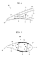
- the wind turbine rotor blade 100 having a super cap structure which satisfies both lightweight requirement and strength requirement as shown in Fig. 5 .
- the wind turbine rotor blade 100 includes a later-described outer skin material 11, leading edge sandwich materials 12, super cap materials (main strength materials) 13, trailing edge sandwich materials 14 and sheer webs (crossbeam materials) 15.
- the leading edge sandwich materials 12 and the trailing edge sandwich materials 14 have a sandwich structure in which the outer skin material 11 and the inner skin material 17 form a skin material, and a resin foam body such as PVC and wood material such as balsa form a core material.
- a symbol 16 represents an adhesive 16 which connects (couples) the super cap materials 13 and the sheer webs 15 to each other.
- a safety factor of a buckling strength and safety factors of material strengths (tensile strength and strength against compression) of members constituting the wind turbine rotor blade 100 can substantially be set equal to each other (e.g., 2), it is possible to further reduce the weight of the wind turbine rotor blade.
- the trailing edge sandwich material 14 and/or a back side and/or front side of the outer skin material 11 located closer to a trailing edge 18 than a trailing edge of the trailing edge sandwich material 14 are buckled by a load in an edge direction (directions of a leading edge and a trailing edge: direction perpendicular to the flap direction).
- a cross-sectional area of the super cap material 13 is maintained constant, a width of the super cap material 13 (length of a cord direction (lateral direction in Fig. 5 )) is reduced, a thickness of the super cap material 13 is increased, and an interval between the sheer webs 15 (distance between the sheer web 15 located on the side of the leading edge and the sheer web 15 located on the side of the trailing edge) is reduced.
- a width of the trailing edge sandwich material 14 (length in the cord direction (lateral direction in Fig. 5 )) is increased, and the buckling strength of the trailing edge sandwich material 14 against a load in an edge direction is further deteriorated.
- the present invention has been accomplished in view of the above circumstances, and it is an object of the invention to provided a wind turbine rotor blade and a wind-generating wind turbine capable of enhancing a buckling strength against a load in an edge direction, capable of bringing a safety factor of the buckling strength close to a safety factor of a material strength, and capable of further reducing a weight of each of the wind turbine rotor blades and the wind-generating wind turbine.
- a wind turbine rotor blade according to a first aspect of the invention including outer skin materials made of fiber-reinforced plastic, a sheer web, and a trailing edge sandwich material disposed closer to a trailing edge than a trailing edge end of the crossbeam material, wherein a reinforcing material is provided on an inner surface of the outer skin material on a front side located closer to the trailing edge than a trailing edge end of the trailing edge sandwich materials.
- a thickness of the front side outer skin material located closer to the trailing edge than the trailing edge end of the trailing edge sandwich material is increased by the reinforcing material disposed on the inner surface of the front side outer skin material. Therefore, it is possible to enhance bending rigidity of the trailing edge in the edge direction, a buckling strength of the trailing edge against a load in the edge direction can be enhanced. A safety factor of the buckling strength can be brought close to a safety factor of the material strength, and it is possible to further reduce the weight.
- the reinforcing material is mounted on the inner surface of the front side outer skin material located closer to the trailing edge than the trailing edge end of the trailing edge sandwich material. Therefore, it is possible to thin the reinforcing material as compared with a case where the reinforcing material is mounted on an inner surface of the back side outer skin material, and it is easy to avoid interference between an upper surface of the reinforcing material and the inner surface of the outer skin material.
- the lowest order buckling mode with respect to a load in the edge direction is a trailing edge sandwich material or an outer skin material located closer to the trailing edge than the trailing edge end of the trailing edge sandwich material.
- the thickness of the reinforcing material is excessively increased, the outer skin material and the inner surface interfere with each other and therefore, it is preferable that the thickness is reduced as thin as possible.
- the wind turbine rotor blade has an outer surface shape like the wind turbine blade (the back side is closer to a flat surface as compared with the front side near the trailing edge)
- the buckling strength is lowered when the reinforcing material is disposed on the back side as compared with the case where the reinforcing material is disposed on the front side due to influence of curvature.
- the reinforcing material is disposed on the front side, it is possible to thin the reinforcing material as compared with a case where the reinforcing material is disposed on the back side, and it is easy to avoid the interference between the upper surface of the reinforcing material and the inner surface of the outer skin material.
- the reinforcing material includes a lightweight core material, an upper surface side skin material disposed on an upper surface side of the lightweight core material, and a lower surface side skin material disposed on a lower surface side of the lightweight core material, and the upper surface side skin material and/or the lower surface side skin material is made of fiber-reinforced plastic in which reinforced fiber is oriented in a longitudinal direction of the blade.
- the reinforced fibers constituting the upper surface side skin material and/or the lower surface side skin material is arranged along the longitudinal direction of the blade. Therefore, it is possible to further enhance the bending rigidity of the trailing edge in the edge direction, and to enhance the buckling strength of the trailing edge against the load in the edge direction. It is possible to bring the safety factor of the buckling strength close to the safety factor of the material strength, and further reduce the weight.
- the wind-generating wind turbine of a second aspect of the invention includes wind turbine rotor blades capable of enhancing the bending rigidity in the trailing edge in the edge direction, and capable of enhancing the buckling strength in the trailing edge against a load in the edge direction, capable of bringing a safety factor of the buckling strength close to a safety factor of the material strength, and capable of further reducing the weight.
- the wind-generating wind turbine of the second aspect of the invention it is possible to reduce, in weight, the rotation bearing which connects the rotor head and the root portion of the wind turbine rotor blade to each other, and the connecting shaft which is disposed in the rotor head and which gives rotating motion to the wind turbine blade.
- a load applied to the tower which supports the wind turbine rotor blades and the rotor head can be reduced.
- the wind turbine rotor blade of the invention it is possible to enhance a buckling strength against a load in an edge direction, bring a safety factor of the buckling strength close to a safety factor of a material strength, and further reduce a weight of the wind turbine rotor blade.
- FIG. 1 is a side view showing a wind-generating wind turbine having the wind turbine rotor blades according to the first embodiment of the present invention.
- Fig. 2 is a sectional view of the wind turbine rotor blade of the embodiment.
- Fig. 3 is an enlarged sectional view of an essential portion in Fig. 2 .
- the wind-generating wind turbine 1 includes a column (also called “tower") 2 standing on a foundation B, a nacelle 3 disposed on an upper end of the column 2, and a rotor head 4 provided on a nacelle 3 such that the rotor head 4 can rotate around a substantially horizontal axis.
- a plurality of (e.g., three) wind turbine rotor blades 5 are radially mounted on the rotor head 4 around its rotation axis. According to this, a force of wind which impinges on the wind turbine rotor blades 5 from a direction of the rotation axis of the rotor head 4 is converted into power which rotates the rotor head 4 around its rotation axis.
- the column 2 is formed by connecting a plurality of (e.g., three) units (not shown) in the vertical direction.
- the nacelle 3 is disposed on the uppermost one of the units which constitute the column 2.
- the nacelle 3 includes a nacelle bed plate (not shown) mounted on the upper end of the column 2, and a cover 6 covering the nacelle bed plate from above.
- each of the wind turbine rotor blades 5 is formed as a super cap structure which satisfies both lightweight requirement and strength requirement.
- the wind turbine rotor blade 5 includes outer skin materials 11, leading edge sandwich materials 12, super cap materials (main strength material) 13, trailing edge sandwich materials 14 and sheer webs (crossbeam materials) 15.
- the outer skin material 11, the super cap material 13 and an inner skin material 17 are made (formed) of fiber-reinforced plastic (FRP) .
- the super cap material 13 is formed by laminating many fiber-reinforced plastic layers on one another.
- the super cap materials 13 are provided on a back side and a front side of the wind turbine rotor blade 5 one each such that the super cap materials 13 are in contact with end surfaces of back sides (upper sides in Fig. 2 ) of the sheer webs 15 and in contact with end surfaces of front sides (lower sides in Fig. 2 ) of the sheer webs 15.
- the super cap materials 13 and the sheer webs 15 are connected (coupled) to each other through an adhesive 16 which is cured at room temperature.
- the leading edge sandwich material 12 and the trailing edge sandwich material 14 have a sandwich structure in which the outer skin material 11 and the inner skin material 17 form a skin material, and a resin foam body such as PVC and wood material such as balsa form a core material.
- the leading edge sandwich material 12 and the trailing edge sandwich material 14 are sandwiched between the outer skin material 11 and the inner skin material 17.
- the super cap structure the bending strength of the wind turbine rotor blade 5 in a flap direction is maintained mainly by the super cap material 13 made of fiber-reinforced plastic.
- the leading edge sandwich material 12 and the trailing edge sandwich material 14 are auxiliary used for maintaining the buckling strength of the wind turbine rotor blade 5.
- a reinforcing material 20 is provided (disposed) on an inner surface 19 of the front side outer skin material 11 located closer to a trailing edge 18 than a trailing edge end of the trailing edge sandwich material 14.
- the reinforcing material 20 is formed by laminating, on another, many (e.g., twenty) fiber-reinforced plastic layers in which reinforced fibers (not shown) are oriented in a longitudinal direction of the wind turbine rotor blade 5 (direction perpendicular to sheet surfaces in Figs. 2 and 3 ) , and a thickness of the reinforcing material 20 is about 20 mm.
- the reinforcing material 20 is connected (coupled) to the inner surface 19 of the front side outer skin material 11 through an adhesive 21 which is cured at room temperature.
- a thickness of the front side outer skin material 11 located closer to the trailing edge 18 than the trailing edge end of the trailing edge sandwich material 14 is increased by the reinforcing material 20 disposed on the inner surface 19. Therefore, the bending rigidity of the trailing edge in the edge direction can be enhanced, and the buckling strength of the trailing edge against a load in the edge direction can be enhanced. A safety factor of the buckling strength can be brought close to a safety factor of the material strength, and it is possible to further reduce the weight. As a result, even if a width of the trailing edge sandwich material 14 (length in a cord direction (lateral direction in Fig.
- the buckling strength of the trailing edge sandwich material 14 against the load in the edge direction can be prevented from being lowered. Therefore, an interval between the sheer webs 15 in the cord direction, i.e., a distance between the sheer web 15 located on the side of the leading edge and the sheer web 15 located on the side of the trailing edge can be reduced. Therefore, it is possible to reduce the width of the super cap material 13 (at that time, the super cap material 13 is thickened while maintaining the cross-sectional area of the super cap material 13 at the same value), and the buckling strength of the super cap material 13 against the load in the flap direction can be enhanced.
- the reinforcing material 20 is mounted only on the inner surface 19 of the front side outer skin material 11 located closer to the trailing edge 18 than the trailing edge end of the trailing edge sandwich material 14. Therefore, as compared with a case where the reinforcing material is mounted only on the inner surface of the back side outer skin material, it is possible to thin the reinforcing material, and it is easy to avoid interference between an upper surface of the reinforcing material and an inner surface of the outer skin material.
- the lowest order buckling mode with respect to a load in the edge direction is a trailing edge sandwich material or a outer skin material located closer to the trailing edge than the trailing edge end of the trailing edge sandwich material.
- the reinforcing material is mounted on the inner surface of the outer skin material located closer to the trailing edge than the trailing edge end of the trailing edge sandwich material, there is a possibility that Euler buckling of the reinforcing material becomes the lowest order buckling mode.
- the wind turbine rotor blade has an outer surface shape like the wind turbine blade (the back side is closer to a flat surface as compared with the front side near the trailing edge)
- the buckling strength is lowered when the reinforcing material is disposed on the back side as compared with the case where the reinforcing material is disposed on the front side due to influence of curvature.
- the reinforcing material is disposed on the front side, it is possible to thin the reinforcing material as compared with a case where the reinforcing material is disposed on the back side, and it is easy to avoid the interference between the upper surface of the reinforcing material and the inner surface of the outer skin material.
- the reinforced fibers constituting the reinforcing material 20 are arranged along the longitudinal direction of the blade, it is possible to further enhance the bending rigidity of the trailing edge in the edge direction, and to enhance the buckling strength of the trailing edge against the load in the edge direction. It is possible to bring the safety factor of the buckling strength close to the safety factor of the material strength, and the weight can further be reduced.
- the wind-generating wind turbine 1 having the wind turbine rotor blades 5 of the embodiment it is possible to reduce, in weight, the rotation bearing which connects the rotor head and the root portion of the wind turbine rotor blade to each other, and the connecting shaft which is disposed in the rotor head and which gives rotating motion to the wind turbine blade.
- a load applied to the tower 2 which supports the wind turbine rotor blades 5 and the rotor head 4 can be reduced.
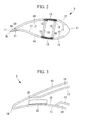
- FIG. 4 is similar to Fig. 3 , and is an enlarged sectional view of an essential portion of the wind turbine rotor blade according to the second embodiment.
- the wind turbine rotor blade 30 of the second embodiment is different from that of the first embodiment in that the wind turbine rotor blade 30 includes a reinforcing material 31 instead of the reinforcing material 20. Since other constituent elements are the same as those of the first embodiment, description of these constituent elements will be omitted.
- the same members as those of the first embodiment are designated with the same symbols.
- the reinforcing material 31 of this embodiment includes a lightweight core material 32, a (upper surface side) skin material 33 disposed on an upper surface side of the lightweight core material 32, and a (lower surface side) skin material 34 disposed on a lower surface side of the lightweight core material 32.
- the lightweight core material 32 is made (formed) of resin foam body such as PVC or wood material such as balsa, and is sandwiched between the skin material 33 and the skin material 34.
- the skin materials 33 and 34 have the same lengths as a length of corresponding (opposing) end surfaces of the lightweight core material 32 in the cord direction (lateral direction in Fig. 4 ).
- the skin materials 33 and 34 are made (formed) of fiber-reinforced plastic in which reinforced fibers (not shown) are oriented in the longitudinal direction of the wind turbine rotor blade 30 (direction perpendicular to a sheet surface of Fig. 4 ).
- the skin material 33 is adhered to an end surface on the upper surface side of the lightweight core material 32, the skin material 34 is adhered to an end surface on the lower surface side of the lightweight core material 32, and the lightweight core material 32 and the skin materials 33 and 34 are integrally formed (configured) together.
- the inner surface 19 of the front side outer skin material 11 and the skin material 34 are connected (coupled) to each other through an adhesive 23 which is cured at room temperature.
- the reinforcing material 31 is of sandwich structure in which the lightweight core material 32 is sandwiched between the skin material 33 and the skin material 34. Therefore, it is possible to reduce the reinforcing material 31 and the entire wind turbine rotor blade 30 in weight, and the bending rigidity of the trailing edge in the edge direction can be enhanced.
- the buckling strength of the trailing edge against a load in the edge direction can be enhanced, the safety factor of the buckling strength can be brought close to the safety factor of the material strength, and it is possible to further reduce the weight. Since other effect is the same as that of the first embodiment, description thereof is omitted here.
- the present invention is not limited to the above-described embodiments, and the invention can variously be changed and modified within a range not departing from a subject matter of the invention.
- the reinforcing materials 20 and 31 can be applied not only to the wind turbine rotor blade having the structure shown in Fig. 5 , but also be applied to a wind turbine rotor blade having sheer webs of box structure. ⁇ Reference Signs List ⁇
Abstract
Description
- The present invention relates to a wind turbine rotor blade constituting a wind-generating wind turbine, and to the wind-generating wind turbine.
- As a wind turbine rotor blade one disclosed in
patent document 1 is known for example. -
- In recent years, there is proposed a wind
turbine rotor blade 100 having a super cap structure which satisfies both lightweight requirement and strength requirement as shown inFig. 5 . The windturbine rotor blade 100 includes a later-describedouter skin material 11, leadingedge sandwich materials 12, super cap materials (main strength materials) 13, trailingedge sandwich materials 14 and sheer webs (crossbeam materials) 15. The leadingedge sandwich materials 12 and the trailingedge sandwich materials 14 have a sandwich structure in which theouter skin material 11 and theinner skin material 17 form a skin material, and a resin foam body such as PVC and wood material such as balsa form a core material.
InFig. 5 , asymbol 16 represents an adhesive 16 which connects (couples) thesuper cap materials 13 and thesheer webs 15 to each other. - If a safety factor of a buckling strength and safety factors of material strengths (tensile strength and strength against compression) of members constituting the wind turbine rotor blade 100 (specifically the
outer skin material 11, the leadingedge sandwich material 12, thesuper cap material 13, the trailingedge sandwich material 14 and the sheer web 15) can substantially be set equal to each other (e.g., 2), it is possible to further reduce the weight of the wind turbine rotor blade. - According to the wind
turbine rotor blade 100 shown inFig. 5 , however, there is an adverse possibility that thesuper cap material 13 is buckled by a load in a flap direction (longitudinal direction: vertical direction inFig. 5 ) before the windturbine rotor blade 100 exerts 100% material strength, the trailingedge sandwich material 14 and/or a back side and/or front side of theouter skin material 11 located closer to atrailing edge 18 than a trailing edge of the trailingedge sandwich material 14 are buckled by a load in an edge direction (directions of a leading edge and a trailing edge: direction perpendicular to the flap direction). - To increase a buckling strength of the
super cap material 13 against a load in the flap direction, a cross-sectional area of thesuper cap material 13 is maintained constant, a width of the super cap material 13 (length of a cord direction (lateral direction inFig. 5 )) is reduced, a thickness of thesuper cap material 13 is increased, and an interval between the sheer webs 15 (distance between thesheer web 15 located on the side of the leading edge and thesheer web 15 located on the side of the trailing edge) is reduced.
However, there is a problem that a width of the trailing edge sandwich material 14 (length in the cord direction (lateral direction inFig. 5 )) is increased, and the buckling strength of the trailingedge sandwich material 14 against a load in an edge direction is further deteriorated. - The present invention has been accomplished in view of the above circumstances, and it is an object of the invention to provided a wind turbine rotor blade and a wind-generating wind turbine capable of enhancing a buckling strength against a load in an edge direction, capable of bringing a safety factor of the buckling strength close to a safety factor of a material strength, and capable of further reducing a weight of each of the wind turbine rotor blades and the wind-generating wind turbine.
- To solve the above problem, the present invention employed the following means.
A wind turbine rotor blade according to a first aspect of the invention including outer skin materials made of fiber-reinforced plastic, a sheer web, and a trailing edge sandwich material disposed closer to a trailing edge than a trailing edge end of the crossbeam material, wherein a reinforcing material is provided on an inner surface of the outer skin material on a front side located closer to the trailing edge than a trailing edge end of the trailing edge sandwich materials. - According to the wind turbine rotor blade of the first aspect of the invention, a thickness of the front side outer skin material located closer to the trailing edge than the trailing edge end of the trailing edge sandwich material is increased by the reinforcing material disposed on the inner surface of the front side outer skin material. Therefore, it is possible to enhance bending rigidity of the trailing edge in the edge direction, a buckling strength of the trailing edge against a load in the edge direction can be enhanced. A safety factor of the buckling strength can be brought close to a safety factor of the material strength, and it is possible to further reduce the weight.
According to the wind turbine rotor blade of the first aspect of the invention, the reinforcing material is mounted on the inner surface of the front side outer skin material located closer to the trailing edge than the trailing edge end of the trailing edge sandwich material. Therefore, it is possible to thin the reinforcing material as compared with a case where the reinforcing material is mounted on an inner surface of the back side outer skin material, and it is easy to avoid interference between an upper surface of the reinforcing material and the inner surface of the outer skin material.
According to the conventional wind turbine rotor blade, the lowest order buckling mode with respect to a load in the edge direction is a trailing edge sandwich material or an outer skin material located closer to the trailing edge than the trailing edge end of the trailing edge sandwich material. When the reinforcing material is mounted on the inner surface of the outer skin material located closer to the trailing edge than the trailing edge end of the trailing edge sandwich material, there is a possibility that Euler buckling of the reinforcing material becomes the lowest order buckling mode. In order to make Euler buckling strength of the reinforcing material greater than the buckling strength of the trailing edge sandwich material or of the outer skin material located closer to the trailing edge than the trailing edge sandwich material while maintaining the cross-sectional area of the reinforcing material, it is only necessary to reduce the width of the reinforcing material and to increase the thickness thereof. However, if the thickness of the reinforcing material is excessively increased, the outer skin material and the inner surface interfere with each other and therefore, it is preferable that the thickness is reduced as thin as possible. When the wind turbine rotor blade has an outer surface shape like the wind turbine blade (the back side is closer to a flat surface as compared with the front side near the trailing edge) , if a case where the reinforcing material having the same cross section shape is disposed only on the back side and a case where the reinforcing material is disposed only on the front side are compared with each other, the buckling strength is lowered when the reinforcing material is disposed on the back side as compared with the case where the reinforcing material is disposed on the front side due to influence of curvature. Therefore, if the reinforcing material is disposed on the front side, it is possible to thin the reinforcing material as compared with a case where the reinforcing material is disposed on the back side, and it is easy to avoid the interference between the upper surface of the reinforcing material and the inner surface of the outer skin material. - In the above wind turbine rotor blade, it is preferable that the reinforcing material includes a lightweight core material, an upper surface side skin material disposed on an upper surface side of the lightweight core material, and a lower surface side skin material disposed on a lower surface side of the lightweight core material, and the upper surface side skin material and/or the lower surface side skin material is made of fiber-reinforced plastic in which reinforced fiber is oriented in a longitudinal direction of the blade.
- According to the wind turbine rotor blade, the reinforced fibers constituting the upper surface side skin material and/or the lower surface side skin material is arranged along the longitudinal direction of the blade. Therefore, it is possible to further enhance the bending rigidity of the trailing edge in the edge direction, and to enhance the buckling strength of the trailing edge against the load in the edge direction. It is possible to bring the safety factor of the buckling strength close to the safety factor of the material strength, and further reduce the weight.
- The wind-generating wind turbine of a second aspect of the invention includes wind turbine rotor blades capable of enhancing the bending rigidity in the trailing edge in the edge direction, and capable of enhancing the buckling strength in the trailing edge against a load in the edge direction, capable of bringing a safety factor of the buckling strength close to a safety factor of the material strength, and capable of further reducing the weight.
- According to the wind-generating wind turbine of the second aspect of the invention, it is possible to reduce, in weight, the rotation bearing which connects the rotor head and the root portion of the wind turbine rotor blade to each other, and the connecting shaft which is disposed in the rotor head and which gives rotating motion to the wind turbine blade. A load applied to the tower which supports the wind turbine rotor blades and the rotor head can be reduced.
- According to the wind turbine rotor blade of the invention, it is possible to enhance a buckling strength against a load in an edge direction, bring a safety factor of the buckling strength close to a safety factor of a material strength, and further reduce a weight of the wind turbine rotor blade.
-
- {
Fig. 1} Fig. 1 is a side view showing a wind-generating wind turbine having wind turbine rotor blades according to a first embodiment of the present invention. - {
Fig. 2} Fig. 2 is a sectional view of the wind turbine rotor blade of the first embodiment of the invention. - {
Fig. 3} Fig. 3 is an enlarged sectional view of an essential portion inFig. 2 . - {
Fig. 4} Fig. 4 is similar toFig. 3 , and is an enlarged sectional view of an essential portion of a wind turbine rotor blade according to a second embodiment. - {
Fig. 5} Fig. 5 is similar toFig. 2 , and is a sectional view showing a conventional wind turbine rotor blade. - A first embodiment of wind turbine rotor blades according to the present invention will be described with reference to
Figs. 1 to 3 .
Fig. 1 is a side view showing a wind-generating wind turbine having the wind turbine rotor blades according to the first embodiment of the present invention.Fig. 2 is a sectional view of the wind turbine rotor blade of the embodiment.Fig. 3 is an enlarged sectional view of an essential portion inFig. 2 . - As shown in
Fig. 1 , the wind-generatingwind turbine 1 includes a column (also called "tower") 2 standing on a foundation B, anacelle 3 disposed on an upper end of thecolumn 2, and arotor head 4 provided on anacelle 3 such that therotor head 4 can rotate around a substantially horizontal axis.
A plurality of (e.g., three) windturbine rotor blades 5 are radially mounted on therotor head 4 around its rotation axis. According to this, a force of wind which impinges on the windturbine rotor blades 5 from a direction of the rotation axis of therotor head 4 is converted into power which rotates therotor head 4 around its rotation axis. - The
column 2 is formed by connecting a plurality of (e.g., three) units (not shown) in the vertical direction.
Thenacelle 3 is disposed on the uppermost one of the units which constitute thecolumn 2. Thenacelle 3 includes a nacelle bed plate (not shown) mounted on the upper end of thecolumn 2, and acover 6 covering the nacelle bed plate from above. - As shown in
Fig. 2 , each of the windturbine rotor blades 5 is formed as a super cap structure which satisfies both lightweight requirement and strength requirement. The windturbine rotor blade 5 includesouter skin materials 11, leadingedge sandwich materials 12, super cap materials (main strength material) 13, trailingedge sandwich materials 14 and sheer webs (crossbeam materials) 15. - The
outer skin material 11, thesuper cap material 13 and aninner skin material 17 are made (formed) of fiber-reinforced plastic (FRP) . Thesuper cap material 13 is formed by laminating many fiber-reinforced plastic layers on one another. Thesuper cap materials 13 are provided on a back side and a front side of the windturbine rotor blade 5 one each such that thesuper cap materials 13 are in contact with end surfaces of back sides (upper sides inFig. 2 ) of thesheer webs 15 and in contact with end surfaces of front sides (lower sides inFig. 2 ) of thesheer webs 15. Thesuper cap materials 13 and thesheer webs 15 are connected (coupled) to each other through an adhesive 16 which is cured at room temperature. - The leading
edge sandwich material 12 and the trailingedge sandwich material 14 have a sandwich structure in which theouter skin material 11 and theinner skin material 17 form a skin material, and a resin foam body such as PVC and wood material such as balsa form a core material. The leadingedge sandwich material 12 and the trailingedge sandwich material 14 are sandwiched between theouter skin material 11 and theinner skin material 17.
According to the super cap structure, the bending strength of the windturbine rotor blade 5 in a flap direction is maintained mainly by thesuper cap material 13 made of fiber-reinforced plastic. The leadingedge sandwich material 12 and the trailingedge sandwich material 14 are auxiliary used for maintaining the buckling strength of the windturbine rotor blade 5. - In the wind
turbine rotor blade 5 of the embodiment, a reinforcingmaterial 20 is provided (disposed) on aninner surface 19 of the front sideouter skin material 11 located closer to a trailingedge 18 than a trailing edge end of the trailingedge sandwich material 14.
As shown inFigs. 2 and 3 , the reinforcingmaterial 20 is formed by laminating, on another, many (e.g., twenty) fiber-reinforced plastic layers in which reinforced fibers (not shown) are oriented in a longitudinal direction of the wind turbine rotor blade 5 (direction perpendicular to sheet surfaces inFigs. 2 and 3 ) , and a thickness of the reinforcingmaterial 20 is about 20 mm. The reinforcingmaterial 20 is connected (coupled) to theinner surface 19 of the front sideouter skin material 11 through an adhesive 21 which is cured at room temperature. - According to the wind
turbine rotor blade 5 of the embodiment, a thickness of the front sideouter skin material 11 located closer to the trailingedge 18 than the trailing edge end of the trailingedge sandwich material 14 is increased by the reinforcingmaterial 20 disposed on theinner surface 19. Therefore, the bending rigidity of the trailing edge in the edge direction can be enhanced, and the buckling strength of the trailing edge against a load in the edge direction can be enhanced. A safety factor of the buckling strength can be brought close to a safety factor of the material strength, and it is possible to further reduce the weight.
As a result, even if a width of the trailing edge sandwich material 14 (length in a cord direction (lateral direction inFig. 2 )) is increased, the buckling strength of the trailingedge sandwich material 14 against the load in the edge direction can be prevented from being lowered. Therefore, an interval between thesheer webs 15 in the cord direction, i.e., a distance between thesheer web 15 located on the side of the leading edge and thesheer web 15 located on the side of the trailing edge can be reduced. Therefore, it is possible to reduce the width of the super cap material 13 (at that time, thesuper cap material 13 is thickened while maintaining the cross-sectional area of thesuper cap material 13 at the same value), and the buckling strength of thesuper cap material 13 against the load in the flap direction can be enhanced. - According to the wind
turbine rotor blade 5 of the embodiment, the reinforcingmaterial 20 is mounted only on theinner surface 19 of the front sideouter skin material 11 located closer to the trailingedge 18 than the trailing edge end of the trailingedge sandwich material 14. Therefore, as compared with a case where the reinforcing material is mounted only on the inner surface of the back side outer skin material, it is possible to thin the reinforcing material, and it is easy to avoid interference between an upper surface of the reinforcing material and an inner surface of the outer skin material.
According to the conventional wind turbine rotor blade, the lowest order buckling mode with respect to a load in the edge direction is a trailing edge sandwich material or a outer skin material located closer to the trailing edge than the trailing edge end of the trailing edge sandwich material. When the reinforcing material is mounted on the inner surface of the outer skin material located closer to the trailing edge than the trailing edge end of the trailing edge sandwich material, there is a possibility that Euler buckling of the reinforcing material becomes the lowest order buckling mode. In order to make Euler buckling strength of the reinforcing material greater than the buckling strength of the trailing edge sandwich material or of the outer skin material located closer to the trailing edge than the trailing edge sandwich material while maintaining the cross-sectional area of the reinforcing material, it is only necessary to reduce the width of the reinforcing material and to increase the thickness thereof. However, if the thickness of the reinforcing material is excessively increased, the outer skin material and the inner surface interfere with each other and therefore, it is preferable that the thickness is reduced as thin as possible. When the wind turbine rotor blade has an outer surface shape like the wind turbine blade (the back side is closer to a flat surface as compared with the front side near the trailing edge) , if a case where the reinforcing material having the same cross section shape is disposed only on the back side and a case there the reinforcing material is disposed only on the front side are compared with each other, the buckling strength is lowered when the reinforcing material is disposed on the back side as compared with the case where the reinforcing material is disposed on the front side due to influence of curvature. Therefore, if the reinforcing material is disposed on the front side, it is possible to thin the reinforcing material as compared with a case where the reinforcing material is disposed on the back side, and it is easy to avoid the interference between the upper surface of the reinforcing material and the inner surface of the outer skin material. - According to the wind
turbine rotor blade 5 of the embodiment, since the reinforced fibers constituting the reinforcingmaterial 20 are arranged along the longitudinal direction of the blade, it is possible to further enhance the bending rigidity of the trailing edge in the edge direction, and to enhance the buckling strength of the trailing edge against the load in the edge direction. It is possible to bring the safety factor of the buckling strength close to the safety factor of the material strength, and the weight can further be reduced. - According to the wind-generating
wind turbine 1 having the windturbine rotor blades 5 of the embodiment, it is possible to reduce, in weight, the rotation bearing which connects the rotor head and the root portion of the wind turbine rotor blade to each other, and the connecting shaft which is disposed in the rotor head and which gives rotating motion to the wind turbine blade. A load applied to thetower 2 which supports the windturbine rotor blades 5 and therotor head 4 can be reduced. - A second embodiment of the wind turbine rotor blade of the present invention will be described with reference to
Fig. 4 .
Fig. 4 is similar toFig. 3 , and is an enlarged sectional view of an essential portion of the wind turbine rotor blade according to the second embodiment.
The windturbine rotor blade 30 of the second embodiment is different from that of the first embodiment in that the windturbine rotor blade 30 includes a reinforcingmaterial 31 instead of the reinforcingmaterial 20. Since other constituent elements are the same as those of the first embodiment, description of these constituent elements will be omitted.
The same members as those of the first embodiment are designated with the same symbols. - As shown in
Fig. 4 , the reinforcingmaterial 31 of this embodiment includes alightweight core material 32, a (upper surface side)skin material 33 disposed on an upper surface side of thelightweight core material 32, and a (lower surface side)skin material 34 disposed on a lower surface side of thelightweight core material 32. - The
lightweight core material 32 is made (formed) of resin foam body such as PVC or wood material such as balsa, and is sandwiched between theskin material 33 and theskin material 34.
Theskin materials lightweight core material 32 in the cord direction (lateral direction inFig. 4 ). Theskin materials Fig. 4 ). - The
skin material 33 is adhered to an end surface on the upper surface side of thelightweight core material 32, theskin material 34 is adhered to an end surface on the lower surface side of thelightweight core material 32, and thelightweight core material 32 and theskin materials inner surface 19 of the front sideouter skin material 11 and theskin material 34 are connected (coupled) to each other through an adhesive 23 which is cured at room temperature. - According to the wind
turbine rotor blade 30 of this embodiment, the reinforcingmaterial 31 is of sandwich structure in which thelightweight core material 32 is sandwiched between theskin material 33 and theskin material 34. Therefore, it is possible to reduce the reinforcingmaterial 31 and the entire windturbine rotor blade 30 in weight, and the bending rigidity of the trailing edge in the edge direction can be enhanced. The buckling strength of the trailing edge against a load in the edge direction can be enhanced, the safety factor of the buckling strength can be brought close to the safety factor of the material strength, and it is possible to further reduce the weight.
Since other effect is the same as that of the first embodiment, description thereof is omitted here. - The present invention is not limited to the above-described embodiments, and the invention can variously be changed and modified within a range not departing from a subject matter of the invention.
For example, the reinforcingmaterials Fig. 5 , but also be applied to a wind turbine rotor blade having sheer webs of box structure. {Reference Signs List} -
- 1
- wind-generating wind turbine
- 2
- column (tower)
- 3
- nacelle
- 4
- rotor head
- 5
- wind turbine rotor blade
- 6
- nacelle cover
- 11
- outer skin material
- 12
- leading edge sandwich material
- 13
- super cap material (main strength material)
- 14
- trailing edge sandwich material
- 15
- sheer web (crossbeam material)
- 16
- adhesive
- 17
- inner skin material
- 18
- trailing edge
- 19
- inner surface
- 20
- reinforcing material
- 30
- wind turbine rotor blade
- 31
- reinforcing material
- 32
- lightweight core material
- 33
- skin material (upper surface side skin material)
- 34
- skin material (lower surface side skin material)
- 100
- wind turbine rotor blade
- B
- foundation
Claims (3)
- A wind turbine rotor blade comprising outer skin materials made of fiber-reinforced plastic, a crossbeam material, and a trailing edge lightweight core material disposed closer to a trailing edge than a trailing edge end of the crossbeam material, wherein
a reinforcing material is provided on an inner surface of the outer skin material on a front side located closer to the trailing edge than a trailing edge end of the trailing edge lightweight core material. - The wind turbine rotor blade according to claim 1, wherein
the reinforcing material includes a lightweight core material, an upper surface side skin material disposed on an upper surface side of the lightweight core material, and a lower surface side skin material disposed on a lower surface side of the lightweight core material, and
the upper surface side skin material and/or the lower surface side skin material is made of fiber-reinforced plastic in which reinforced fiber is oriented in a longitudinal direction of the blade. - A wind-generating wind turbine comprising the wind turbine rotor blade according to claim 1 or 2.
Applications Claiming Priority (2)
| Application Number | Priority Date | Filing Date | Title |
|---|---|---|---|
| JP2009296152A JP5427597B2 (en) | 2009-12-25 | 2009-12-25 | Wind turbine rotor |
| PCT/JP2010/073370 WO2011078337A1 (en) | 2009-12-25 | 2010-12-24 | Windmill rotary vane |
Publications (3)
| Publication Number | Publication Date |
|---|---|
| EP2518314A1 true EP2518314A1 (en) | 2012-10-31 |
| EP2518314A4 EP2518314A4 (en) | 2014-05-28 |
| EP2518314B1 EP2518314B1 (en) | 2018-06-27 |
Family
ID=44195862
Family Applications (1)
| Application Number | Title | Priority Date | Filing Date |
|---|---|---|---|
| EP10839566.6A Not-in-force EP2518314B1 (en) | 2009-12-25 | 2010-12-24 | Wind turbine rotor blade and wind turbine |
Country Status (5)
| Country | Link |
|---|---|
| US (1) | US8651822B2 (en) |
| EP (1) | EP2518314B1 (en) |
| JP (1) | JP5427597B2 (en) |
| AU (1) | AU2010336191A1 (en) |
| WO (1) | WO2011078337A1 (en) |
Cited By (1)
| Publication number | Priority date | Publication date | Assignee | Title |
|---|---|---|---|---|
| CN102927051A (en) * | 2012-11-15 | 2013-02-13 | 江苏中联风能机械有限公司 | Improved blade of large-sized air cooling axial flow fan |
Families Citing this family (6)
| Publication number | Priority date | Publication date | Assignee | Title |
|---|---|---|---|---|
| ES2342638B1 (en) * | 2007-02-28 | 2011-05-13 | GAMESA INNOVATION & TECHNOLOGY, S.L. | A MULTI-PANEL AIRPLANE SHOVEL. |
| JP5427597B2 (en) * | 2009-12-25 | 2014-02-26 | 三菱重工業株式会社 | Wind turbine rotor |
| IN2012DN01230A (en) * | 2009-12-25 | 2015-04-10 | Mitsubishi Heavy Ind Ltd | |
| US8973871B2 (en) * | 2013-01-26 | 2015-03-10 | The Boeing Company | Box structures for carrying loads and methods of making the same |
| KR101678015B1 (en) * | 2014-12-30 | 2016-11-21 | 한국에너지기술연구원 | Composite blade having Local reinforcement structure |
| DE102016007675A1 (en) * | 2016-06-24 | 2017-12-28 | Senvion Gmbh | Trailing edge belt with rectangular cross section |
Citations (3)
| Publication number | Priority date | Publication date | Assignee | Title |
|---|---|---|---|---|
| US4976587A (en) * | 1988-07-20 | 1990-12-11 | Dwr Wind Technologies Inc. | Composite wind turbine rotor blade and method for making same |
| US20090169392A1 (en) * | 2006-03-24 | 2009-07-02 | Mitsubishi Heavy Industries Ltd. | Wind turbine blade with sufficiently high strength and light weight |
| AU2008357369A1 (en) * | 2008-06-05 | 2009-12-10 | Mitsubishi Heavy Industries, Ltd. | Wind turbine blade and wind power generator using the same |
Family Cites Families (16)
| Publication number | Priority date | Publication date | Assignee | Title |
|---|---|---|---|---|
| JP2002137307A (en) * | 2000-11-02 | 2002-05-14 | Toray Ind Inc | Blade structure of windmill made of fiber-reinforced resin |
| JP3825346B2 (en) * | 2001-03-27 | 2006-09-27 | 三菱重工業株式会社 | Composite blade for wind turbine generator |
| CA2454038C (en) * | 2001-07-19 | 2009-09-29 | Neg Micon A/S | Wind turbine blade |
| NL1024463C2 (en) * | 2003-10-06 | 2005-04-07 | Polymarin Holding B V | Rotor for use in a wind turbine and method for making the rotor. |
| ATE540220T1 (en) * | 2005-11-03 | 2012-01-15 | Vestas Wind Sys As | WIND TURBINE BLADE WITH ONE OR MORE VIBRATION DAMPERS |
| EP2104785B1 (en) * | 2007-01-16 | 2014-06-25 | Bladena ApS | Reinforced blade for wind turbine |
| US20090140527A1 (en) * | 2007-11-30 | 2009-06-04 | General Electric Company | Wind turbine blade stiffeners |
| CA2741479A1 (en) * | 2008-10-22 | 2010-04-29 | Vec Industries, L.L.C. | Wind turbine blade and method for manufacturing thereof |
| JP2011032988A (en) * | 2009-08-05 | 2011-02-17 | Nitto Denko Corp | Foam filler for wind turbine generator blade, foam filling part for wind turbine generator blade, wind turbine generator blade, wind turbine generator, and method of manufacturing wind turbine generator blade |
| JP2011032987A (en) * | 2009-08-05 | 2011-02-17 | Nitto Denko Corp | Reinforcing sheet for wind turbine generator blade, reinforcing structure of wind turbine generator blade, wind turbine generator, and method of reinforcing wind turbine generator blade |
| US8702397B2 (en) * | 2009-12-01 | 2014-04-22 | General Electric Company | Systems and methods of assembling a rotor blade for use in a wind turbine |
| JP5308323B2 (en) * | 2009-12-22 | 2013-10-09 | 三菱重工業株式会社 | Wind turbine blade and wind power generator using the same |
| JP5484892B2 (en) * | 2009-12-25 | 2014-05-07 | 三菱重工業株式会社 | Wind turbine rotor |
| JP5427597B2 (en) * | 2009-12-25 | 2014-02-26 | 三菱重工業株式会社 | Wind turbine rotor |
| IN2012DN01230A (en) * | 2009-12-25 | 2015-04-10 | Mitsubishi Heavy Ind Ltd | |
| US8142164B2 (en) * | 2009-12-31 | 2012-03-27 | General Electric Company | Rotor blade for use with a wind turbine and method for assembling rotor blade |
-
2009
- 2009-12-25 JP JP2009296152A patent/JP5427597B2/en not_active Expired - Fee Related
-
2010
- 2010-12-24 WO PCT/JP2010/073370 patent/WO2011078337A1/en active Application Filing
- 2010-12-24 EP EP10839566.6A patent/EP2518314B1/en not_active Not-in-force
- 2010-12-24 AU AU2010336191A patent/AU2010336191A1/en not_active Abandoned
-
2011
- 2011-03-24 US US13/070,998 patent/US8651822B2/en active Active
Patent Citations (3)
| Publication number | Priority date | Publication date | Assignee | Title |
|---|---|---|---|---|
| US4976587A (en) * | 1988-07-20 | 1990-12-11 | Dwr Wind Technologies Inc. | Composite wind turbine rotor blade and method for making same |
| US20090169392A1 (en) * | 2006-03-24 | 2009-07-02 | Mitsubishi Heavy Industries Ltd. | Wind turbine blade with sufficiently high strength and light weight |
| AU2008357369A1 (en) * | 2008-06-05 | 2009-12-10 | Mitsubishi Heavy Industries, Ltd. | Wind turbine blade and wind power generator using the same |
Non-Patent Citations (1)
| Title |
|---|
| See also references of WO2011078337A1 * |
Cited By (1)
| Publication number | Priority date | Publication date | Assignee | Title |
|---|---|---|---|---|
| CN102927051A (en) * | 2012-11-15 | 2013-02-13 | 江苏中联风能机械有限公司 | Improved blade of large-sized air cooling axial flow fan |
Also Published As
| Publication number | Publication date |
|---|---|
| EP2518314A4 (en) | 2014-05-28 |
| WO2011078337A1 (en) | 2011-06-30 |
| JP2011137388A (en) | 2011-07-14 |
| JP5427597B2 (en) | 2014-02-26 |
| AU2010336191A1 (en) | 2012-01-19 |
| US20110171035A1 (en) | 2011-07-14 |
| US8651822B2 (en) | 2014-02-18 |
| EP2518314B1 (en) | 2018-06-27 |
Similar Documents
| Publication | Publication Date | Title |
|---|---|---|
| US8556590B2 (en) | Wind-turbine rotor blade | |
| EP2532891B1 (en) | Rotary blade of windmill and method of manufacturing rotary blade of windmill | |
| EP2518314B1 (en) | Wind turbine rotor blade and wind turbine | |
| US8480371B2 (en) | Wind turbine rotor blade and wind-generating wind turbine | |
| EP2224127B1 (en) | Improved spar cap for wind turbine blades | |
| US11028824B2 (en) | Wind turbine blade with a trailing edge spacing section | |
| US8186964B2 (en) | Spar assembly for a wind turbine rotor blade | |
| EP2357358B1 (en) | Rotor blade of a wind turbine | |
| DK178020B1 (en) | SAVE CAP UNIT FOR A WINDOW MILLER CIRCUIT | |
| US20110211971A1 (en) | Rotor blade for a wind power plant, wind power plant and method for the production of a rotor blade | |
| JP2011137386A5 (en) | ||
| EP3071830B1 (en) | Wind turbine blade with wave shaped trailing edge | |
| JP2011137388A5 (en) | ||
| EP2728169A2 (en) | Structural members for a wind turbine rotor blade | |
| EP2526287B1 (en) | A wind turbine rotor blade having a buckling trailing edge | |
| US20130064675A1 (en) | Wind turbine rotor blade | |
| WO2023274482A1 (en) | A wind turbine blade |
Legal Events
| Date | Code | Title | Description |
|---|---|---|---|
| PUAI | Public reference made under article 153(3) epc to a published international application that has entered the european phase |
Free format text: ORIGINAL CODE: 0009012 |
|
| 17P | Request for examination filed |
Effective date: 20120110 |
|
| AK | Designated contracting states |
Kind code of ref document: A1 Designated state(s): AL AT BE BG CH CY CZ DE DK EE ES FI FR GB GR HR HU IE IS IT LI LT LU LV MC MK MT NL NO PL PT RO RS SE SI SK SM TR |
|
| DAX | Request for extension of the european patent (deleted) | ||
| REG | Reference to a national code |
Ref country code: DE Ref legal event code: R079 Ref document number: 602010051571 Country of ref document: DE Free format text: PREVIOUS MAIN CLASS: F03D0011000000 Ipc: F03D0001060000 |
|
| A4 | Supplementary search report drawn up and despatched |
Effective date: 20140430 |
|
| RIC1 | Information provided on ipc code assigned before grant |
Ipc: F03D 1/06 20060101AFI20140424BHEP |
|
| 17Q | First examination report despatched |
Effective date: 20160411 |
|
| GRAP | Despatch of communication of intention to grant a patent |
Free format text: ORIGINAL CODE: EPIDOSNIGR1 |
|
| INTG | Intention to grant announced |
Effective date: 20180223 |
|
| GRAS | Grant fee paid |
Free format text: ORIGINAL CODE: EPIDOSNIGR3 |
|
| GRAA | (expected) grant |
Free format text: ORIGINAL CODE: 0009210 |
|
| AK | Designated contracting states |
Kind code of ref document: B1 Designated state(s): AL AT BE BG CH CY CZ DE DK EE ES FI FR GB GR HR HU IE IS IT LI LT LU LV MC MK MT NL NO PL PT RO RS SE SI SK SM TR |
|
| REG | Reference to a national code |
Ref country code: GB Ref legal event code: FG4D |
|
| REG | Reference to a national code |
Ref country code: AT Ref legal event code: REF Ref document number: 1012577 Country of ref document: AT Kind code of ref document: T Effective date: 20180715 |
|
| REG | Reference to a national code |
Ref country code: DE Ref legal event code: R096 Ref document number: 602010051571 Country of ref document: DE |
|
| REG | Reference to a national code |
Ref country code: IE Ref legal event code: FG4D |
|
| PG25 | Lapsed in a contracting state [announced via postgrant information from national office to epo] |
Ref country code: LT Free format text: LAPSE BECAUSE OF FAILURE TO SUBMIT A TRANSLATION OF THE DESCRIPTION OR TO PAY THE FEE WITHIN THE PRESCRIBED TIME-LIMIT Effective date: 20180627 Ref country code: SE Free format text: LAPSE BECAUSE OF FAILURE TO SUBMIT A TRANSLATION OF THE DESCRIPTION OR TO PAY THE FEE WITHIN THE PRESCRIBED TIME-LIMIT Effective date: 20180627 Ref country code: NO Free format text: LAPSE BECAUSE OF FAILURE TO SUBMIT A TRANSLATION OF THE DESCRIPTION OR TO PAY THE FEE WITHIN THE PRESCRIBED TIME-LIMIT Effective date: 20180927 Ref country code: FI Free format text: LAPSE BECAUSE OF FAILURE TO SUBMIT A TRANSLATION OF THE DESCRIPTION OR TO PAY THE FEE WITHIN THE PRESCRIBED TIME-LIMIT Effective date: 20180627 Ref country code: BG Free format text: LAPSE BECAUSE OF FAILURE TO SUBMIT A TRANSLATION OF THE DESCRIPTION OR TO PAY THE FEE WITHIN THE PRESCRIBED TIME-LIMIT Effective date: 20180927 |
|
| REG | Reference to a national code |
Ref country code: NL Ref legal event code: MP Effective date: 20180627 |
|
| REG | Reference to a national code |
Ref country code: LT Ref legal event code: MG4D |
|
| PG25 | Lapsed in a contracting state [announced via postgrant information from national office to epo] |
Ref country code: LV Free format text: LAPSE BECAUSE OF FAILURE TO SUBMIT A TRANSLATION OF THE DESCRIPTION OR TO PAY THE FEE WITHIN THE PRESCRIBED TIME-LIMIT Effective date: 20180627 Ref country code: HR Free format text: LAPSE BECAUSE OF FAILURE TO SUBMIT A TRANSLATION OF THE DESCRIPTION OR TO PAY THE FEE WITHIN THE PRESCRIBED TIME-LIMIT Effective date: 20180627 Ref country code: GR Free format text: LAPSE BECAUSE OF FAILURE TO SUBMIT A TRANSLATION OF THE DESCRIPTION OR TO PAY THE FEE WITHIN THE PRESCRIBED TIME-LIMIT Effective date: 20180928 Ref country code: RS Free format text: LAPSE BECAUSE OF FAILURE TO SUBMIT A TRANSLATION OF THE DESCRIPTION OR TO PAY THE FEE WITHIN THE PRESCRIBED TIME-LIMIT Effective date: 20180627 |
|
| REG | Reference to a national code |
Ref country code: AT Ref legal event code: MK05 Ref document number: 1012577 Country of ref document: AT Kind code of ref document: T Effective date: 20180627 |
|
| PG25 | Lapsed in a contracting state [announced via postgrant information from national office to epo] |
Ref country code: NL Free format text: LAPSE BECAUSE OF FAILURE TO SUBMIT A TRANSLATION OF THE DESCRIPTION OR TO PAY THE FEE WITHIN THE PRESCRIBED TIME-LIMIT Effective date: 20180627 |
|
| PG25 | Lapsed in a contracting state [announced via postgrant information from national office to epo] |
Ref country code: AT Free format text: LAPSE BECAUSE OF FAILURE TO SUBMIT A TRANSLATION OF THE DESCRIPTION OR TO PAY THE FEE WITHIN THE PRESCRIBED TIME-LIMIT Effective date: 20180627 Ref country code: IS Free format text: LAPSE BECAUSE OF FAILURE TO SUBMIT A TRANSLATION OF THE DESCRIPTION OR TO PAY THE FEE WITHIN THE PRESCRIBED TIME-LIMIT Effective date: 20181027 Ref country code: PL Free format text: LAPSE BECAUSE OF FAILURE TO SUBMIT A TRANSLATION OF THE DESCRIPTION OR TO PAY THE FEE WITHIN THE PRESCRIBED TIME-LIMIT Effective date: 20180627 Ref country code: EE Free format text: LAPSE BECAUSE OF FAILURE TO SUBMIT A TRANSLATION OF THE DESCRIPTION OR TO PAY THE FEE WITHIN THE PRESCRIBED TIME-LIMIT Effective date: 20180627 Ref country code: CZ Free format text: LAPSE BECAUSE OF FAILURE TO SUBMIT A TRANSLATION OF THE DESCRIPTION OR TO PAY THE FEE WITHIN THE PRESCRIBED TIME-LIMIT Effective date: 20180627 Ref country code: RO Free format text: LAPSE BECAUSE OF FAILURE TO SUBMIT A TRANSLATION OF THE DESCRIPTION OR TO PAY THE FEE WITHIN THE PRESCRIBED TIME-LIMIT Effective date: 20180627 Ref country code: SK Free format text: LAPSE BECAUSE OF FAILURE TO SUBMIT A TRANSLATION OF THE DESCRIPTION OR TO PAY THE FEE WITHIN THE PRESCRIBED TIME-LIMIT Effective date: 20180627 |
|
| PG25 | Lapsed in a contracting state [announced via postgrant information from national office to epo] |
Ref country code: ES Free format text: LAPSE BECAUSE OF FAILURE TO SUBMIT A TRANSLATION OF THE DESCRIPTION OR TO PAY THE FEE WITHIN THE PRESCRIBED TIME-LIMIT Effective date: 20180627 Ref country code: SM Free format text: LAPSE BECAUSE OF FAILURE TO SUBMIT A TRANSLATION OF THE DESCRIPTION OR TO PAY THE FEE WITHIN THE PRESCRIBED TIME-LIMIT Effective date: 20180627 Ref country code: IT Free format text: LAPSE BECAUSE OF FAILURE TO SUBMIT A TRANSLATION OF THE DESCRIPTION OR TO PAY THE FEE WITHIN THE PRESCRIBED TIME-LIMIT Effective date: 20180627 |
|
| REG | Reference to a national code |
Ref country code: DE Ref legal event code: R097 Ref document number: 602010051571 Country of ref document: DE |
|
| PLBE | No opposition filed within time limit |
Free format text: ORIGINAL CODE: 0009261 |
|
| STAA | Information on the status of an ep patent application or granted ep patent |
Free format text: STATUS: NO OPPOSITION FILED WITHIN TIME LIMIT |
|
| PG25 | Lapsed in a contracting state [announced via postgrant information from national office to epo] |
Ref country code: DK Free format text: LAPSE BECAUSE OF FAILURE TO SUBMIT A TRANSLATION OF THE DESCRIPTION OR TO PAY THE FEE WITHIN THE PRESCRIBED TIME-LIMIT Effective date: 20180627 |
|
| 26N | No opposition filed |
Effective date: 20190328 |
|
| REG | Reference to a national code |
Ref country code: CH Ref legal event code: PL |
|
| PG25 | Lapsed in a contracting state [announced via postgrant information from national office to epo] |
Ref country code: LU Free format text: LAPSE BECAUSE OF NON-PAYMENT OF DUE FEES Effective date: 20181224 Ref country code: MC Free format text: LAPSE BECAUSE OF FAILURE TO SUBMIT A TRANSLATION OF THE DESCRIPTION OR TO PAY THE FEE WITHIN THE PRESCRIBED TIME-LIMIT Effective date: 20180627 Ref country code: SI Free format text: LAPSE BECAUSE OF FAILURE TO SUBMIT A TRANSLATION OF THE DESCRIPTION OR TO PAY THE FEE WITHIN THE PRESCRIBED TIME-LIMIT Effective date: 20180627 |
|
| REG | Reference to a national code |
Ref country code: IE Ref legal event code: MM4A |
|
| REG | Reference to a national code |
Ref country code: BE Ref legal event code: MM Effective date: 20181231 |
|
| PG25 | Lapsed in a contracting state [announced via postgrant information from national office to epo] |
Ref country code: IE Free format text: LAPSE BECAUSE OF NON-PAYMENT OF DUE FEES Effective date: 20181224 |
|
| PG25 | Lapsed in a contracting state [announced via postgrant information from national office to epo] |
Ref country code: BE Free format text: LAPSE BECAUSE OF NON-PAYMENT OF DUE FEES Effective date: 20181231 Ref country code: AL Free format text: LAPSE BECAUSE OF FAILURE TO SUBMIT A TRANSLATION OF THE DESCRIPTION OR TO PAY THE FEE WITHIN THE PRESCRIBED TIME-LIMIT Effective date: 20180627 |
|
| PG25 | Lapsed in a contracting state [announced via postgrant information from national office to epo] |
Ref country code: CH Free format text: LAPSE BECAUSE OF NON-PAYMENT OF DUE FEES Effective date: 20181231 Ref country code: LI Free format text: LAPSE BECAUSE OF NON-PAYMENT OF DUE FEES Effective date: 20181231 |
|
| PG25 | Lapsed in a contracting state [announced via postgrant information from national office to epo] |
Ref country code: MT Free format text: LAPSE BECAUSE OF NON-PAYMENT OF DUE FEES Effective date: 20181224 |
|
| PG25 | Lapsed in a contracting state [announced via postgrant information from national office to epo] |
Ref country code: TR Free format text: LAPSE BECAUSE OF FAILURE TO SUBMIT A TRANSLATION OF THE DESCRIPTION OR TO PAY THE FEE WITHIN THE PRESCRIBED TIME-LIMIT Effective date: 20180627 |
|
| PG25 | Lapsed in a contracting state [announced via postgrant information from national office to epo] |
Ref country code: PT Free format text: LAPSE BECAUSE OF FAILURE TO SUBMIT A TRANSLATION OF THE DESCRIPTION OR TO PAY THE FEE WITHIN THE PRESCRIBED TIME-LIMIT Effective date: 20180627 |
|
| PG25 | Lapsed in a contracting state [announced via postgrant information from national office to epo] |
Ref country code: CY Free format text: LAPSE BECAUSE OF FAILURE TO SUBMIT A TRANSLATION OF THE DESCRIPTION OR TO PAY THE FEE WITHIN THE PRESCRIBED TIME-LIMIT Effective date: 20180627 Ref country code: MK Free format text: LAPSE BECAUSE OF NON-PAYMENT OF DUE FEES Effective date: 20180627 Ref country code: HU Free format text: LAPSE BECAUSE OF FAILURE TO SUBMIT A TRANSLATION OF THE DESCRIPTION OR TO PAY THE FEE WITHIN THE PRESCRIBED TIME-LIMIT; INVALID AB INITIO Effective date: 20101224 |
|
| PGFP | Annual fee paid to national office [announced via postgrant information from national office to epo] |
Ref country code: FR Payment date: 20201112 Year of fee payment: 11 Ref country code: GB Payment date: 20201216 Year of fee payment: 11 Ref country code: DE Payment date: 20201208 Year of fee payment: 11 |
|
| REG | Reference to a national code |
Ref country code: DE Ref legal event code: R119 Ref document number: 602010051571 Country of ref document: DE |
|
| GBPC | Gb: european patent ceased through non-payment of renewal fee |
Effective date: 20211224 |
|
| PG25 | Lapsed in a contracting state [announced via postgrant information from national office to epo] |
Ref country code: GB Free format text: LAPSE BECAUSE OF NON-PAYMENT OF DUE FEES Effective date: 20211224 Ref country code: DE Free format text: LAPSE BECAUSE OF NON-PAYMENT OF DUE FEES Effective date: 20220701 |
|
| PG25 | Lapsed in a contracting state [announced via postgrant information from national office to epo] |
Ref country code: FR Free format text: LAPSE BECAUSE OF NON-PAYMENT OF DUE FEES Effective date: 20211231 |