EP2460720A1 - Structural element of a rotorcraft for reducing aerodynamic drag - Google Patents
Structural element of a rotorcraft for reducing aerodynamic drag Download PDFInfo
- Publication number
- EP2460720A1 EP2460720A1 EP20110009080 EP11009080A EP2460720A1 EP 2460720 A1 EP2460720 A1 EP 2460720A1 EP 20110009080 EP20110009080 EP 20110009080 EP 11009080 A EP11009080 A EP 11009080A EP 2460720 A1 EP2460720 A1 EP 2460720A1
- Authority
- EP
- European Patent Office
- Prior art keywords
- fairing
- rear portion
- discontinuous
- structural element
- plane
- Prior art date
- Legal status (The legal status is an assumption and is not a legal conclusion. Google has not performed a legal analysis and makes no representation as to the accuracy of the status listed.)
- Granted
Links
- 230000003247 decreasing effect Effects 0.000 claims description 4
- 230000001788 irregular Effects 0.000 claims description 3
- 230000001174 ascending effect Effects 0.000 claims 1
- 230000008901 benefit Effects 0.000 description 5
- 239000012530 fluid Substances 0.000 description 3
- 230000009467 reduction Effects 0.000 description 3
- 230000010355 oscillation Effects 0.000 description 2
- 239000008188 pellet Substances 0.000 description 2
- 241001646071 Prioneris Species 0.000 description 1
- 238000007792 addition Methods 0.000 description 1
- 230000004075 alteration Effects 0.000 description 1
- 230000008859 change Effects 0.000 description 1
- 239000000470 constituent Substances 0.000 description 1
- 238000010276 construction Methods 0.000 description 1
- 230000000694 effects Effects 0.000 description 1
- 239000000446 fuel Substances 0.000 description 1
- 230000005484 gravity Effects 0.000 description 1
- 238000012423 maintenance Methods 0.000 description 1
- 230000004048 modification Effects 0.000 description 1
- 238000012986 modification Methods 0.000 description 1
- 230000000737 periodic effect Effects 0.000 description 1
- 230000000306 recurrent effect Effects 0.000 description 1
- 230000037303 wrinkles Effects 0.000 description 1
Images
Classifications
-
- B—PERFORMING OPERATIONS; TRANSPORTING
- B64—AIRCRAFT; AVIATION; COSMONAUTICS
- B64C—AEROPLANES; HELICOPTERS
- B64C23/00—Influencing air flow over aircraft surfaces, not otherwise provided for
- B64C23/06—Influencing air flow over aircraft surfaces, not otherwise provided for by generating vortices
-
- B—PERFORMING OPERATIONS; TRANSPORTING
- B64—AIRCRAFT; AVIATION; COSMONAUTICS
- B64C—AEROPLANES; HELICOPTERS
- B64C27/00—Rotorcraft; Rotors peculiar thereto
- B64C27/82—Rotorcraft; Rotors peculiar thereto characterised by the provision of an auxiliary rotor or fluid-jet device for counter-balancing lifting rotor torque or changing direction of rotorcraft
-
- B—PERFORMING OPERATIONS; TRANSPORTING
- B64—AIRCRAFT; AVIATION; COSMONAUTICS
- B64C—AEROPLANES; HELICOPTERS
- B64C1/00—Fuselages; Constructional features common to fuselages, wings, stabilising surfaces or the like
- B64C1/0009—Aerodynamic aspects
-
- B—PERFORMING OPERATIONS; TRANSPORTING
- B64—AIRCRAFT; AVIATION; COSMONAUTICS
- B64C—AEROPLANES; HELICOPTERS
- B64C21/00—Influencing air flow over aircraft surfaces by affecting boundary layer flow
- B64C21/10—Influencing air flow over aircraft surfaces by affecting boundary layer flow using other surface properties, e.g. roughness
-
- B—PERFORMING OPERATIONS; TRANSPORTING
- B64—AIRCRAFT; AVIATION; COSMONAUTICS
- B64C—AEROPLANES; HELICOPTERS
- B64C27/00—Rotorcraft; Rotors peculiar thereto
- B64C27/04—Helicopters
-
- B—PERFORMING OPERATIONS; TRANSPORTING
- B64—AIRCRAFT; AVIATION; COSMONAUTICS
- B64C—AEROPLANES; HELICOPTERS
- B64C7/00—Structures or fairings not otherwise provided for
-
- B—PERFORMING OPERATIONS; TRANSPORTING
- B64—AIRCRAFT; AVIATION; COSMONAUTICS
- B64C—AEROPLANES; HELICOPTERS
- B64C27/00—Rotorcraft; Rotors peculiar thereto
- B64C27/82—Rotorcraft; Rotors peculiar thereto characterised by the provision of an auxiliary rotor or fluid-jet device for counter-balancing lifting rotor torque or changing direction of rotorcraft
- B64C2027/8254—Shrouded tail rotors, e.g. "Fenestron" fans
-
- Y—GENERAL TAGGING OF NEW TECHNOLOGICAL DEVELOPMENTS; GENERAL TAGGING OF CROSS-SECTIONAL TECHNOLOGIES SPANNING OVER SEVERAL SECTIONS OF THE IPC; TECHNICAL SUBJECTS COVERED BY FORMER USPC CROSS-REFERENCE ART COLLECTIONS [XRACs] AND DIGESTS
- Y02—TECHNOLOGIES OR APPLICATIONS FOR MITIGATION OR ADAPTATION AGAINST CLIMATE CHANGE
- Y02T—CLIMATE CHANGE MITIGATION TECHNOLOGIES RELATED TO TRANSPORTATION
- Y02T50/00—Aeronautics or air transport
- Y02T50/10—Drag reduction
Definitions
- the invention relates to the general technical field of aeronautics and more specifically to the construction of structural elements of aircraft, particularly rotary wing aircraft such as rotorcraft. These structural elements, which should be differentiated from bearing surfaces, are often at the origin of aerodynamic drag.
- the present invention more particularly relates to a shrouded tail rotor, said Fenestron®, a helicopter, or more generally a structural element of a certain thickness, whose shape generates aerodynamic drag.
- some Fenestron®-type faired rear rotors comprise a rear portion ending in a straight cap, for example a part extending substantially orthogonal to the direction of travel and closing the rear part of the Fenestron fairing.
- the fairing of such a rear rotor therefore suddenly has a zero width downstream from the free end.
- Such a shape has a large wake and is responsible for a significant part of its aerodynamic drag. Such a shape therefore penalizes the aerodynamic performance of the aircraft in forward flight.
- the relative thickness is the value of the ratio between the maximum thickness of the object in the direction transverse to the flow, over the length of the object (dimension occupied by the object in the longitudinal direction to the flow ).
- Such a relative thickness generates a need for length (rope fairing) important, given the fairing width necessary to accommodate the anti-torque rotor.
- the use of such a profiled portion therefore increases the mass of the apparatus. This increase in mass is furthermore located far behind the center of gravity of the apparatus, thus generating problems of centering the apparatus.
- a profiled part generates flight quality problems, in particular a road instability of the aircraft. Such road instability can thus result from reduced drag in flight but which has an unstable detachment position.
- the wake beat not being located in the same place, then introduces natural oscillations self-maintained on the efforts created by the hull, including yaw. The pilot can then feel from the tail of the helicopter, yawing oscillations around the direction (road) he has fixed.
- Such a profiled part can also generate asymmetry in lateral flight of the apparatus. Indeed, the greater the lateral surface of the hull, the more we oppose the movement in side flight. For example, the fact of extending the back of a fenestron will provide a larger surface wind side flight.
- a rotor blade of a rotorcraft comprising aerodynamic reliefs improving the aerodynamic characteristics of said blade, in order to promote the flow of the surrounding fluid.
- the reliefs are formed in particular of waves formed in the general plane of the blade, in raising or digging. These waves realize variations in the thickness of the blade, distributed along its wingspan in extrados and also in intrados. These reliefs are also formed by the curve variation of the blade according to its depth, said reliefs being arranged in sawtooths distributed along the span of said blade at least at its leading edge, or even on its edge. leak.
- This document therefore very specifically relates to the bearing surfaces of a rotorcraft.
- the document GB577524 describes a rotary wing aircraft provided with an anti-torque rear rotor. On opposite side walls of a tail boom of the aircraft are provided suction openings of the anti-torque rotor.
- the blades of a main rotor cause a downward flow, which is forced into the fuselage through an air inlet under this main rotor, and is channeled to the suction openings on the opposite sidewalls of the main beam. tail.
- the document EP1527992 describes a float-shaped aerodynamic lift surface arranged to create a vortex. Along the longitudinal direction of the aircraft, concave grooves are provided.
- the invention proposes a new aircraft structure element of the genus rotorcraft, in particular a helicopter, the shape of which makes it possible to overcome the limitations mentioned above, and consequently to reduce its aerodynamic drag in flight. 'advancement.
- the invention provides a fairing portion for an anti-torque rotor, the shape of said fairing portion, to reduce its aerodynamic drag in forward flight.
- the invention proposes a Fenestron whose fairing shape makes it possible to reduce its aerodynamic drag in forward flight.
- the invention takes the form of a fairing for a structural element of an aircraft, comprising a rear portion substantially orthogonal to the longitudinal direction of the aircraft, said rear portion extending between two trailing edges spaced apart. and thus having a predetermined width, said rear portion closing at least in part the internal volume defined by the fairing and generating aerodynamic drag in forward flight, characterized in that the rear portion has at least at the trailing edges, a disturbed shape on the paths of the air flow.
- the disturbed form comprises reliefs and recesses extending over the entire surface of the rear portion located between the trailing edges.
- the raised and recessed form constitutes regular undulations in dimensions.
- the raised and recessed shape constitutes irregular undulations in dimensions.
- At least a portion of the corrugations extends from one trailing edge to the other.
- At least a portion of the corrugations extends from a trailing edge to at least one intermediate zone of the rear part, said at least one intermediate zone being located between the two edges. leak.
- the disturbed form has protuberances along each trailing edge.
- the disturbed form has cavities along each trailing edge.
- the invention takes the form of a helicopter anti-torque rear rotor for helicopters, comprising a hub on which blades are mounted, means for driving the hub in rotation and means for adjusting the pitch of the blades.
- said rotor comprising a fairing as presented above.
- the fairing comprises two open sides, substantially parallel and located on either side of the hub, said lateral portions each ending rearwardly by a trailing edge, said part rear of the fairing forming a base extending between the trailing edges.
- the rear portion forming the base has at least one curvature in a vertical and longitudinal plane of the aircraft.
- the new structural element or the fairing may either have a shape that incorporates from the outset technical characteristics overcoming the drawbacks mentioned above, or include additions (inserts and / or glued) for example in kit form.
- the invention takes the form of a rotorcraft including a helicopter, comprising a ducted anti-torque rear rotor as presented above.
- the invention has the advantage that its shape, in particular its rear part, makes it possible to reduce the size of the detachment of the average aerodynamic flow, downstream from the structural element or Fenestron. This provides a reduction in drag and therefore a reduction in fuel consumption by the aircraft.
- the overweight generated by the solution according to the invention is negligible.
- Another advantage of the invention lies in the fact that it is a passive solution, introducing no recurrent cost of control or maintenance.
- Another advantage of the invention lies in the fact that it can be applied and adapted to various types and sizes of Fenestrons.
- Another advantage of the invention lies in the fact that it does not affect the flight qualities of the aircraft, especially for different flight points, including the side flight and a strong skidding.
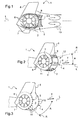
- the figure 1 illustrates an exemplary embodiment of a structural element according to the invention in profile, said structural element forming part of an anti-torque rotor of the genus Fenestron.
- the Fenestron structure comprises a fairing 1, which comprises a rear portion 2 substantially orthogonal to the longitudinal direction L of the aircraft.
- the rear portion 2 extends between two trailing edges 3,4 spaced apart from each other.
- the fairing 1 thus has a determined width, said rear portion 2 closing at least partly the internal volume defined by the fairing 1 and generating aerodynamic drag in forward flight.
- the rear portion 2 has at least at the trailing edges 3,4 a disturbed shape on the paths of the air flow 5, shown by arrows on the figure 1 .
- the fairing 1 advantageously comprises a vertical drift 6 and extends around a hub 7 on which are mounted blades 8 to form the anti-torque rotor of the genus Fenestron.
- the disturbed shape of the rear portion 2 comprises reliefs and recesses extending over the entire surface of the rear portion located between the trailing edges 3 and 4.
- the figure 2 illustrates an exemplary embodiment of a structural element according to the invention in a perspective view, said structural element forming part of an anti-torque rotor of the genus Fenestron.
- the shape, in reliefs and recesses constitutes corrugations 9 regular in dimensions.
- the raised and recessed shape constitutes irregular corrugations 9 in dimensions (not shown).
- At least a portion of the corrugations 9 extends from a trailing edge 3 to the other trailing edge 4.
- At least part of the corrugations 9 extends from a trailing edge 3 or 4 to at least one intermediate zone of the rear part 2, said at least one intermediate zone being located between the two trailing edges 3 and 4.
- the figure 3 illustrates another embodiment of a structural element according to the invention in a perspective view, said structural element forming part of an anti-torque rotor of the genus Fenestron.
- the disturbed form has protuberances along each trailing edge 3 and 4.
- the protuberances 10 are located in the vicinity of each trailing edge 3 and 4 and preferably straddling the trailing edges 3,4 and the rear part 2.
- the corrugations can therefore be restricted in length and remain in the vicinity of the trailing edge, which allows them to be placed on the upper and lower parts of the base.
- the longitudinal direction L is horizontal.
- the transverse span of the fairing 1 defines a transverse direction T also considered horizontal. It is along the transverse direction T that the span of the fairing 1 is extended.
- the longitudinal direction L and the transverse direction E define a plane of attitude (L, T).
- each discontinuous disturbed form and / or each continuous undulation is extended according to a plane of proper orientation, represented in FIGS. Figures 2 and 3 in R.
- Each own orientation plane R of discontinuous disturbed form and / or each continuous undulation is parallel to the transverse direction T, but forms a radial orientation angle A with respect to the plane of attitude (L, T ).
- Some discontinuous disturbed forms and / or continuous undulations form a radial orientation angle A which is said to increase, as on the figure 2 .
- a radial orientation angle A increasing is such that, from the front to the rear of the fairing 1, the plane of proper orientation R which is sequent to the plane of attitude (L, T) towards the front of the fairing 1, is more and more distant from the plane of attitude (L, T) towards the rear of the fairing 1 and towards the top of the fairing 1.
- discontinuous discontinuous shapes and / or continuous undulations form a radial orientation angle A which is said to be decreasing, as on as on the figure 3 .
- Such a decreasing angle of radial orientation A is such that, from the front to the rear of the fairing 1, the plane of proper orientation R which is always sequent to the plane of attitude (L, T) towards the front of the fairing 1, is more and more distant from the trim plane (L, T) towards the rear of the fairing 1 but towards the bottom of the fairing 1.
- Protuberances may also be provided by way of example, to be provided on all visible edges.
- the disturbed form has cavities along each trailing edge 3,4 and preferably straddling the trailing edges 3,4 and the rear part 2 .
- the fairing 1 according to the invention may also be a constituent part of a structural element of an aircraft, not constituting a bearing surface.
- the invention also applies to a ducted anti-torque rear rotor for rotary wing aircraft, in particular for a helicopter.
- the structural element comprises a hub 7 on which the blades 8 are mounted, a drive means rotation of the hub and means for adjusting the blades 8.
- Such a rotor comprises the fairing 1 as presented above.
- the fairing1 comprises two open lateral parts 11 and 12, substantially parallel, and located on either side of the hub 7 (FIG. figure 2 ).
- the open side portions 11 and 12 each end rearwardly by a respective trailing edge 3 and 4 and the rear portion 2 of the fairing 1 forms a straight pellet extending between said trailing edges 3 and 4.
- the rear portion 2 forming the base has at least one curvature in a vertical and longitudinal plane of the aircraft.
- the shape of the fairing 1 according to the invention makes it possible to excite the instabilities of the air vortices 13 according to the span of the rear part 2 forming the base. These transverse instabilities will accelerate the dissipation of the wake and thus reduce the average size of the unstuck zone. This reduction in the average detachment length has the effect of reducing the aerodynamic shape drag of the fairing 1.
- average detachment can be defined in the present invention as the average length of the vortex zone.
- Average detachment is the form of detachment that occurs when calculating or measuring the average field in time of flow. We can for example measure the speeds in the wake and calculate their average value at each point of the wake space. We then obtain a shape of wake average time. For a base, it can usually represent one or two big swirls that are called then average detachments.
Abstract
Description
La présente demande revendique la priorité de la demande
L'invention se rapporte au domaine technique général de l'aéronautique et plus précisément à la construction d'éléments structurels d'aéronefs, en particulier d'aéronefs à voilure tournante tels que les giravions. Ces éléments structurels, qu'il convient de différentier de surfaces portantes, sont souvent à l'origine de traînées aérodynamiques.The invention relates to the general technical field of aeronautics and more specifically to the construction of structural elements of aircraft, particularly rotary wing aircraft such as rotorcraft. These structural elements, which should be differentiated from bearing surfaces, are often at the origin of aerodynamic drag.
Lors de la conception d'aéronefs et notamment de giravions, en particulier d'hélicoptères, il est constant de vouloir réduire au mieux la traînée aérodynamique des différents éléments structurels constituant l'aéronef.When designing aircraft and especially rotorcraft, especially helicopters, it is common to want to minimize the aerodynamic drag of the various structural elements constituting the aircraft.
La présente invention concerne plus particulièrement un rotor arrière caréné, dit Fenestron®, d'un hélicoptère, ou plus généralement un élément de structure d'une certaine épaisseur, dont la forme génère une traînée aérodynamique.The present invention more particularly relates to a shrouded tail rotor, said Fenestron®, a helicopter, or more generally a structural element of a certain thickness, whose shape generates aerodynamic drag.
A titre d'exemple, certains rotors arrières carénés de type Fenestron® comportent une partie arrière se terminant par un culot franc, par exemple une pièce s'étendant sensiblement orthogonalement à la direction d'avancement et refermant la partie arrière du carénage du Fenestron. Le carénage d'un tel rotor arrière présente donc subitement en aval du culot franc, une largeur nulle. Une telle forme présente un sillage important et est responsable d'une part non négligeable de sa traînée aérodynamique. Une telle forme pénalise donc les performances aérodynamiques de l'appareil en vol d'avancement.By way of example, some Fenestron®-type faired rear rotors comprise a rear portion ending in a straight cap, for example a part extending substantially orthogonal to the direction of travel and closing the rear part of the Fenestron fairing. The fairing of such a rear rotor therefore suddenly has a zero width downstream from the free end. Such a shape has a large wake and is responsible for a significant part of its aerodynamic drag. Such a shape therefore penalizes the aerodynamic performance of the aircraft in forward flight.
L'écoulement de l'air, en aval du culot franc est massivement décollé de la structure et ce décollement aérodynamique, c'est-à-dire une zone de concentration de tourbillons et de turbulences relativement étendue, est à l'origine d'une importante dissipation d'énergie ainsi que de vibrations induites par les efforts aérodynamiques.The flow of air downstream of the frank pellet is massively detached from the structure and this aerodynamic detachment, that is to say a zone of concentration of vortices and relatively large turbulence, is at the origin of a significant dissipation of energy as well as vibrations induced by the aerodynamic forces.
Afin de remédier à ces inconvénients, il a été imaginé de remplacer le culot franc par une partie de carénage se terminant par une forme profilée. Un tel changement de forme ne s'avère efficace vis-à-vis de la traînée que si l'épaisseur relative du carénage est inférieure à 15%.In order to remedy these drawbacks, it has been imagined to replace the base cap with a portion of the fairing ending in a profiled shape. Such a change of shape is effective with respect to drag only if the relative thickness of the fairing is less than 15%.
L'épaisseur relative est la valeur du rapport entre l'épaisseur maximale de l'objet dans la direction transversale à l'écoulement, sur la longueur de l'objet (dimension qu'occupe l'objet dans la direction longitudinale à l'écoulement).The relative thickness is the value of the ratio between the maximum thickness of the object in the direction transverse to the flow, over the length of the object (dimension occupied by the object in the longitudinal direction to the flow ).
Une telle épaisseur relative engendre un besoin de longueur (corde du carénage) importante, compte tenu de la largeur de carénage nécessaire pour y loger le rotor anti-couple. L'utilisation d'une telle partie profilée augmente donc la masse de l'appareil. Cette augmentation de masse est en outre localisée très loin en arrière du centre de gravité de l'appareil, générant ainsi des problèmes de centrage de l'appareil. Par ailleurs, une telle partie profilée génère des problèmes de qualité de vol, notamment une instabilité de route de l'appareil. Une telle instabilité de route peut ainsi résulter d'une traînée réduite en vol mais qui présente une position de décollement instable. Le battement du sillage, n'étant pas localisé au même endroit, introduit alors des oscillations naturelles auto-entretenues sur les efforts créés par la carène, notamment en lacet. Le pilote peut alors ressentir en provenance de la queue de l'hélicoptère, des oscillations en lacet autour de la direction (route) qu'il a fixée.Such a relative thickness generates a need for length (rope fairing) important, given the fairing width necessary to accommodate the anti-torque rotor. The use of such a profiled portion therefore increases the mass of the apparatus. This increase in mass is furthermore located far behind the center of gravity of the apparatus, thus generating problems of centering the apparatus. Moreover, such a profiled part generates flight quality problems, in particular a road instability of the aircraft. Such road instability can thus result from reduced drag in flight but which has an unstable detachment position. The wake beat, not being located in the same place, then introduces natural oscillations self-maintained on the efforts created by the hull, including yaw. The pilot can then feel from the tail of the helicopter, yawing oscillations around the direction (road) he has fixed.
Une telle partie profilée peut également générer une dissymétrie en vol latéral de l'appareil. En effet, plus on augmente la surface latérale de la carène, plus on s'opposera au mouvement en vol latéral. A titre d'exemple, le fait de rallonger l'arrière d'un fenestron va offrir une surface plus importante au vent en vol latéral.Such a profiled part can also generate asymmetry in lateral flight of the apparatus. Indeed, the greater the lateral surface of the hull, the more we oppose the movement in side flight. For example, the fact of extending the back of a fenestron will provide a larger surface wind side flight.
On connaît également, par exemple par l'intermédiaire du document
On connaît par ailleurs le document
Par l'altération géométrique du culot de l'objet, on favorise la croissance des instabilités naturelles présentes dans le sillage. Les tourbillons qui sont créés dans la partie de sillage très proche du culot, sont donc naturellement poussés à se dissiper plus vite grâce aux modifications géométriques qui introduisent des perturbations aérodynamiques.By the geometric alteration of the base of the object, we promote the growth of natural instabilities present in the wake. The vortices that are created in the wake section very close to the base, are naturally pushed to dissipate faster thanks to the geometric modifications that introduce aerodynamic disturbances.
Les résultats de ce document ne concernent pas des éléments de structure d'un giravion présentant une certaine épaisseur. En outre, les problèmes de traînée induits par ces perturbations ne sont pas traités dans ce document.The results of this document do not relate to structural elements of a rotorcraft having a certain thickness. In addition, the drag problems induced by these disturbances are not discussed in this document.
Outre les documents
Le document
Le document
Le document
D'autres documents comme
La présente invention est définie par les revendications.The present invention is defined by the claims.
Dans une réalisation, l'invention propose un nouvel élément de structure d'aéronef du genre giravion, notamment un hélicoptère, dont la forme permet de s'affranchir des limitations mentionnées ci-dessus, et par conséquent de réduire sa traînée aérodynamique en vol d'avancement.In one embodiment, the invention proposes a new aircraft structure element of the genus rotorcraft, in particular a helicopter, the shape of which makes it possible to overcome the limitations mentioned above, and consequently to reduce its aerodynamic drag in flight. 'advancement.
Dans une réalisation, l'invention propose une partie de carénage pour un rotor anti-couple, dont la forme de ladite partie de carénage, permet de réduire sa traînée aérodynamique en vol d'avancement.In one embodiment, the invention provides a fairing portion for an anti-torque rotor, the shape of said fairing portion, to reduce its aerodynamic drag in forward flight.
Dans une réalisation, l'invention propose un Fenestron dont la forme du carénage permet de réduire sa traînée aérodynamique en vol d'avancement.In one embodiment, the invention proposes a Fenestron whose fairing shape makes it possible to reduce its aerodynamic drag in forward flight.
Dans une réalisation, l'invention prend la forme d'un carénage pour un élément structurel d'un aéronef, comportant une partie arrière sensiblement orthogonale à la direction longitudinale de l'aéronef, ladite partie arrière s'étendant entre deux bords de fuite espacés et présentant ainsi une largeur déterminée, ladite partie arrière obturant au moins en partie le volume interne délimité par le carénage et générant une traînée aérodynamique en vol d'avancement, caractérisé en ce que la partie arrière présente au moins au niveau des bords de fuite, une forme perturbée sur les trajets de l'écoulement d'air.In one embodiment, the invention takes the form of a fairing for a structural element of an aircraft, comprising a rear portion substantially orthogonal to the longitudinal direction of the aircraft, said rear portion extending between two trailing edges spaced apart. and thus having a predetermined width, said rear portion closing at least in part the internal volume defined by the fairing and generating aerodynamic drag in forward flight, characterized in that the rear portion has at least at the trailing edges, a disturbed shape on the paths of the air flow.
Selon un exemple de réalisation conforme à l'invention, la forme perturbée comporte des reliefs et des creux s'étendant sur toute la surface de la partie arrière localisée entre les bords de fuite.According to an exemplary embodiment according to the invention, the disturbed form comprises reliefs and recesses extending over the entire surface of the rear portion located between the trailing edges.
Selon un exemple de réalisation conforme à l'invention, la forme en reliefs et en creux constitue des ondulations régulières en dimensions.According to an exemplary embodiment according to the invention, the raised and recessed form constitutes regular undulations in dimensions.
Selon un autre exemple de réalisation conforme à l'invention, la forme en reliefs et en creux constitue des ondulations irrégulières en dimensions.According to another exemplary embodiment according to the invention, the raised and recessed shape constitutes irregular undulations in dimensions.
Selon un exemple de réalisation conforme à l'invention, au moins une partie des ondulations s'étend d'un bord de fuite à l'autre.According to an exemplary embodiment according to the invention, at least a portion of the corrugations extends from one trailing edge to the other.
Selon un autre exemple de réalisation conforme à l'invention, au moins une partie des ondulations s'étend d'un bord de fuite à au moins une zone intermédiaire de la partie arrière, ladite au moins une zone intermédiaire étant localisée entre les deux bords de fuite.According to another exemplary embodiment according to the invention, at least a portion of the corrugations extends from a trailing edge to at least one intermediate zone of the rear part, said at least one intermediate zone being located between the two edges. leak.
Selon un exemple de réalisation conforme à l'invention, la forme perturbée comporte des protubérances le long de chaque bord de fuite.According to an exemplary embodiment according to the invention, the disturbed form has protuberances along each trailing edge.
Selon un autre exemple de réalisation conforme à l'invention, la forme perturbée comporte des cavités, le long de chaque bord de fuite.According to another exemplary embodiment according to the invention, the disturbed form has cavities along each trailing edge.
Les objets assignés à l'invention sont également atteints à l'aide d'un élément de structure d'un aéronef comprenant un carénage tel que présenté ci-dessus.The objects assigned to the invention are also achieved with the aid of a structural element of an aircraft comprising a fairing as presented above.
Dans une réalisation, l'invention prend la forme d'un rotor arrière anti-couple caréné pour hélicoptère, comportant un moyeu sur lequel sont montées des pales, un moyen d'entraînement en rotation du moyeu et des moyens de réglage du pas des pales, ledit rotor comprenant un carénage tel que présenté ci-dessus.In one embodiment, the invention takes the form of a helicopter anti-torque rear rotor for helicopters, comprising a hub on which blades are mounted, means for driving the hub in rotation and means for adjusting the pitch of the blades. , said rotor comprising a fairing as presented above.
Selon un exemple de réalisation conforme à l'invention, le carénage comprend deux parties latérales ouvertes, sensiblement parallèles et situées de part et d'autre du moyeu, lesdites parties latérales se terminant chacune vers l'arrière par un bord de fuite, ladite partie arrière du carénage formant un culot s'étendant entre les bords de fuite.According to an exemplary embodiment according to the invention, the fairing comprises two open sides, substantially parallel and located on either side of the hub, said lateral portions each ending rearwardly by a trailing edge, said part rear of the fairing forming a base extending between the trailing edges.
Selon un exemple de réalisation conforme à l'invention, la partie arrière formant le culot, présente au moins une courbure dans un plan vertical et longitudinal de l'aéronef.According to an exemplary embodiment according to the invention, the rear portion forming the base, has at least one curvature in a vertical and longitudinal plane of the aircraft.
Selon un exemple de réalisation conforme à l'invention, le nouvel élément de structure ou le carénage peut soit présenter une forme qui intègre dès le départ des caractéristiques techniques palliant les inconvénients mentionnés ci-dessus, soit comporter des ajouts (pièces rapportées et/ou collées) par exemple sous forme de kit.According to an exemplary embodiment according to the invention, the new structural element or the fairing may either have a shape that incorporates from the outset technical characteristics overcoming the drawbacks mentioned above, or include additions (inserts and / or glued) for example in kit form.
Dans une réalisation, l'invention prend la forme d'un giravion notamment un hélicoptère, comportant un rotor arrière anti-couple caréné tel que présenté ci-dessus.In one embodiment, the invention takes the form of a rotorcraft including a helicopter, comprising a ducted anti-torque rear rotor as presented above.
L'invention présente l'avantage selon lequel sa forme, en particulier de sa partie arrière, permet de réduire la taille du décollement de l'écoulement aérodynamique moyen, en aval de l'élément de structure ou du Fenestron. On obtient ainsi, une réduction de la traînée et par conséquent une réduction de la consommation de carburant par l'aéronef.The invention has the advantage that its shape, in particular its rear part, makes it possible to reduce the size of the detachment of the average aerodynamic flow, downstream from the structural element or Fenestron. This provides a reduction in drag and therefore a reduction in fuel consumption by the aircraft.
En outre, le surpoids engendré par la solution conforme à l'invention, est négligeable.In addition, the overweight generated by the solution according to the invention is negligible.
Un autre avantage de l'invention réside dans le fait qu'il s'agit d'une solution passive, n'introduisant aucun coût récurrent de contrôle ou de maintenance.Another advantage of the invention lies in the fact that it is a passive solution, introducing no recurrent cost of control or maintenance.
Un autre avantage de l'invention réside dans le fait qu'il peut être appliqué et adapté à divers types et tailles de Fenestrons.Another advantage of the invention lies in the fact that it can be applied and adapted to various types and sizes of Fenestrons.
Un autre avantage de l'invention réside dans le fait qu'il n'altère pas les qualités de vol de l'aéronef, notamment pour différents points de vol, y compris le vol latéral et une forte mise en dérapage.Another advantage of the invention lies in the fact that it does not affect the flight qualities of the aircraft, especially for different flight points, including the side flight and a strong skidding.
L'invention et ses avantages apparaîtront avec plus de détails dans le cadre de la description qui suit avec un exemple de réalisation donné à titre illustratif en référence aux figures annexées qui représentent :
- la
figure 1 , un exemple de réalisation d'un élément de structure conforme à l'invention en vue de profil, ledit élément de structure faisant partie d'un rotor anti-couple du genre Fenestron, - la
figure 2 , un exemple vu en perspective, d'un élément de structure faisant partie d'un rotor anti-couple du genre Fenestron, avec des formes perturbées discontinues et aussi des ondulations étendues transversalement en continu d'un bord de fuite à l'autre, - et la
figure 3 , un autre exemple de réalisation d'un élément de structure conforme à l'invention selon une vue en perspective, ledit élément de structure faisant partie d'un rotor anti-couple du genre Fenestron, avec certaines formes perturbées discontinues et / ou ondulations continues d'un bord de fuite à l'autre formant un angle d'orientation radiale par rapport à une direction longitudinale de l'élément de structure et donc de l'aéronef qui n'en est équipé.
- the
figure 1 , an exemplary embodiment of a structural element according to the invention in profile view, said structural element forming part of an anti-torque rotor of the genus Fenestron, - the
figure 2 , an example seen in perspective, of a structural element forming part of an anti-torque rotor of the genus Fenestron, with discontinuous discontinuous shapes and also transversely extended corrugations continuously from one trailing edge to the other, - and the
figure 3 , another embodiment of a structural element according to the invention in a perspective view, said structural element forming part of an anti-torque rotor of the genus Fenestron, with certain discontinuous disturbed forms and / or continuous undulations from one trailing edge to the other forming an angle of radial orientation with respect to a longitudinal direction of the structural element and therefore of the aircraft which is not equipped with it.
Les éléments structurellement et fonctionnellement identiques, présents sur plusieurs figures distinctes sont affectés d'une seule et même référence numérique ou alphanumérique.The structurally and functionally identical elements present in several distinct figures are assigned a single numerical or alphanumeric reference.
La
La structure du Fenestron comprend un carénage 1, lequel comporte une partie arrière 2 sensiblement orthogonale à la direction longitudinale L de l'aéronef. La partie arrière 2 s'étend entre deux bords de fuite 3,4 espacés l'un de l'autre. Le carénage 1 présente ainsi une largeur déterminée, ladite partie arrière 2 obturant au moins en partie le volume interne délimité par le carénage 1 et générant une traînée aérodynamique en vol d'avancement.The Fenestron structure comprises a
La partie arrière 2 présente au moins au niveau des bords de fuite 3,4 une forme perturbée sur les trajets de l'écoulement d'air 5, matérialisés par des flèches sur la
Le carénage 1 comporte avantageusement une dérive verticale 6 et s'étend autour d'un moyeu 7 sur lequel sont montées des pales 8 pour constituer le rotor anti-couple du genre Fenestron.The
Selon un exemple de réalisation conforme à l'invention, la forme perturbée de la partie arrière 2, comporte des reliefs et des creux s'étendant sur toute la surface de la partie arrière localisée entre les bords de fuite 3 et 4.According to an exemplary embodiment according to the invention, the disturbed shape of the
La
Selon cet exemple de réalisation conforme à l'invention, la forme, en reliefs et en creux, constitue des ondulations 9 régulières en dimensions.According to this exemplary embodiment according to the invention, the shape, in reliefs and recesses, constitutes
Selon un autre exemple de réalisation conforme à l'invention, la forme en reliefs et en creux constitue des ondulations 9 irrégulières en dimensions (non représentées).According to another exemplary embodiment according to the invention, the raised and recessed shape constitutes
Selon un exemple de réalisation conforme à l'invention, au moins une partie des ondulations 9 s'étend d'un bord de fuite 3 à l'autre bord de fuite 4.According to an exemplary embodiment according to the invention, at least a portion of the
Selon un autre exemple de réalisation conforme à l'invention, non représenté, au moins une partie des ondulations 9 s'étend d'un bord de fuite 3 ou 4 à au moins une zone intermédiaire de la partie arrière 2, ladite au moins une zone intermédiaire étant localisée entre les deux bords de fuite 3 et 4.According to another exemplary embodiment according to the invention, not shown, at least part of the
La
Dans un tel exemple de réalisation, les ondulations peuvent donc être restreintes en longueur et rester au voisinage du bord de fuite, ce qui permet de les disposer sur les partie hautes et basses du culot.In such an embodiment, the corrugations can therefore be restricted in length and remain in the vicinity of the trailing edge, which allows them to be placed on the upper and lower parts of the base.
Sur les
En fait, on considère d'une part que la direction longitudinale L est horizontale. On considère d'autre part que l'envergure transversale du carénage 1 définit une direction transversale T également considérée horizontale. C'est suivant la direction transversale T qu'est étendue l'envergure du carénage 1. Conjointement, la direction longitudinale L et la direction transversale E définissent un plan d'assiette (L, T).In fact, it is considered on the one hand that the longitudinal direction L is horizontal. On the other hand, it is considered that the transverse span of the
Par ailleurs, chaque forme perturbée discontinue et / ou chaque ondulation continue est étendue suivant un plan d'orientation propre, représenté aux
Certaines formes perturbées discontinues et / ou ondulations continues forment un angle d'orientation radiale A qui est dit croissant, comme sur la
D'autres formes perturbées discontinues et / ou ondulations continues forment un angle d'orientation radiale A qui est dit décroissant, comme sur comme sur la
D'après les figures, on comprend que les divers plans d'orientation propres R des formes perturbées discontinues et / ou certaines ondulations continues sont séquents et ne sont pas parallèles les uns avec les autres.From the figures, it is understood that the various eigenvector planes R discontinuous disturbed forms and / or some continuous undulations are sequential and are not parallel to each other.
Des protubérances peuvent aussi à titre d'exemple, être prévues sur toutes les arêtes apparentes.Protuberances may also be provided by way of example, to be provided on all visible edges.
Selon un autre exemple de réalisation conforme à l'invention, non représenté, la forme perturbée comporte des cavités, le long de chaque bord de fuite 3,4 et de préférence à cheval sur les bords de fuite 3,4 et la partie arrière 2.According to another exemplary embodiment according to the invention, not shown, the disturbed form has cavities along each trailing
Le carénage 1 conforme à l'invention peut également être une partie constitutive d'un élément structurel d'un aéronef, ne constituant pas une surface portante.The
L'invention s'applique également à un rotor arrière anti-couple caréné pour aéronef à voilure tournante, notamment pour un hélicoptère. L'élément structurel comporte un moyeu 7 sur lequel sont montées les pales 8, un moyen d'entraînement en rotation du moyeu et des moyens de réglage des pales 8. Un tel rotor comprend le carénage 1 tel que présenté ci-dessus.The invention also applies to a ducted anti-torque rear rotor for rotary wing aircraft, in particular for a helicopter. The structural element comprises a
Selon un exemple de réalisation conforme à l'invention, le carénage1 comprend deux parties latérales ouvertes 11 et 12, sensiblement parallèles, et situées de part et d'autre du moyeu 7 (
Selon un exemple de réalisation conforme à l'invention, la partie arrière 2 formant le culot, présente au moins une courbure dans un plan vertical et longitudinal de l'aéronef.According to an exemplary embodiment according to the invention, the
La forme du carénage 1 conforme à l'invention permet d'exciter les instabilités des tourbillons d'air 13 selon l'envergure de la partie arrière 2 formant le culot. Ces instabilités transverses vont accélérer la dissipation du sillage et donc réduire la taille moyenne de la zone décollée. Cette réduction de la longueur de décollement moyen a pour effet de réduire la traînée aérodynamique de forme du carénage 1.The shape of the
La notion de « décollement moyen » peut être définie dans la présente invention comme la longueur moyenne de la zone de concentrations tourbillonnaires. Le décollement moyen est la forme du décollement qui apparaît lorsque l'on calcule ou l'on mesure le champ moyen en temps de l'écoulement. On peut par exemple mesurer les vitesses dans le sillage et on calcule leur valeur moyenne en chaque point de l'espace du sillage. On obtient alors une forme de sillage moyen en temps. Pour un culot, cela peut représenter en général un ou deux gros tourbillons que l'on appelle alors décollements moyens.The concept of "average detachment" can be defined in the present invention as the average length of the vortex zone. Average detachment is the form of detachment that occurs when calculating or measuring the average field in time of flow. We can for example measure the speeds in the wake and calculate their average value at each point of the wake space. We then obtain a shape of wake average time. For a base, it can usually represent one or two big swirls that are called then average detachments.
Naturellement, la présente invention est sujette à de nombreuses variations des modes de réalisation décrits, qui ne sortent pas du cadre de l'invention.Naturally, the present invention is subject to many variations of the embodiments described, which do not depart from the scope of the invention.
Claims (14)
caractérisé en ce que la partie arrière (2) présente au moins au niveau des bords de fuite (3,4), au moins une forme perturbée sur les trajets de l'écoulement d'air (5) discontinue transversalement le long de son envergure entre lesdits bords de fuite (3,4).Fairing (1) for a structural element having a substantially longitudinal direction (L), said fairing (1) having a rear portion (2) substantially orthogonal to the longitudinal direction (L), said rear portion (2) extending along a span of the fairing (1) between two trailing edges (3,4) spaced and thus having a predetermined width, said rear portion (2) closing at least partly the internal volume defined by the shroud (1) and generating aerodynamic drag in forward flight,
characterized in that the rear portion (2) has, at least at the trailing edges (3,4), at least one disturbed shape on the paths of the discontinuous air flow (5) transversely along its span. between said trailing edges (3,4).
caractérisé en ce qu' au moins une forme perturbée discontinue comporte des reliefs et des creux s'étendant de manière discontinue transversalement de bord à bord sur toute la surface de la partie arrière (2) localisée entre les bords de fuite (3,4).Fairing (1) according to claim 1,
characterized in that at least one intermittent discontinuous form has reliefs and recesses extending discontinuously transversely from edge to edge over the entire surface of the rear portion (2) located between the trailing edges (3,4) .
caractérisé en ce qu'au moins une forme perturbée discontinue présente des reliefs et creux à dimensions régulières suivant la direction longitudinale (L).Fairing (1) according to claim 1,
characterized in that at least one discontinuous discontinuous form has reliefs and recesses with regular dimensions in the longitudinal direction (L).
caractérisé en ce qu'au moins une forme perturbée discontinue présente des reliefs et creux à dimensions irrégulières suivant la direction longitudinale (L).Fairing (1) according to claim 1,
characterized in that at least one interrupted discontinuous form has reliefs and depressions with irregular dimensions in the longitudinal direction (L).
caractérisé en ce que le carénage (1) comporte au moins une ondulation (9) continue qui s'étend d'un bord de fuite (3) à l'autre (4), en plus d'au moins une forme perturbée discontinue transversalement le long de son envergure.Fairing (1) according to claim 1,
characterized in that the fairing (1) comprises at least one continuous corrugation (9) extending from one trailing edge (3) to the other (4), in addition to at least one intermittently discontinuous disturbed form along its span.
caractérisé en ce qu'au moins une forme perturbée discontinue s'étend d'un bord de fuite (3, 4) à au moins une zone intermédiaire de la partie arrière (2), ladite zone intermédiaire étant localisée entre les deux bords de fuite (3,4).Fairing (1) according to claim 1,
characterized in that at least one intermittent discontinuous form extends from a trailing edge (3, 4) to at least one intermediate area of the trailing portion (2), said intermediate area being located between the two trailing edges (3,4).
caractérisé en ce qu'au moins une forme perturbée discontinue comporte des protubérances (10) le long de chaque bord de fuite (3,4).Fairing (1) according to claim 1,
characterized in that at least one intermittent discontinuous form has protuberances (10) along each trailing edge (3,4).
caractérisé en ce qu'au moins une forme perturbée discontinue comporte des cavités le long de chaque bord de fuite (3,4).Fairing (1) according to claim 1,
characterized in that at least one intermittent discontinuous form has cavities along each trailing edge (3,4).
caractérisé en ce qu'au moins une forme perturbée discontinue et / ou ondulation continue forme un angle d'orientation radiale (A) croissant, ledit angle d'orientation radiale (A) croissant étant tel que, de l'avant vers l'arrière du carénage (1), un plan d'orientation propre (R) qui est séquent à un plan d'assiette (L,T) longitudinal et transversal vers l'avant du carénage (1), est de plus en plus distant dudit plan d'assiette (L,T) vers l'arrière et vers le haut du carénage (1).Fairing (1) according to claim 1,
characterized in that at least one intermittent discontinuous and / or continuous wave shape forms an increasing radial orientation angle (A), said ascending radial orientation angle (A) being such that from front to rear of the fairing (1), a plane of proper orientation (R) which is sequent to a plane of attitude (L, T) longitudinal and transverse towards the front of the fairing (1), is more and more distant from said plane trim (L, T) towards the rear and upwards of the fairing (1).
caractérisé en ce qu'au moins une forme perturbée discontinue et / ou ondulation continue forme un angle d'orientation radiale (A) décroissant, ledit angle d'orientation radiale (A) décroissant étant tel que, de l'avant vers l'arrière du carénage (1), un plan d'orientation propre (R) qui est séquent à un plan d'assiette (L,T) longitudinal et transversal vers l'avant du carénage (1), est de plus en plus distant dudit plan d'assiette (L,T) vers l'arrière et vers le bas du carénage (1).Fairing (1) according to claim 1,
characterized in that at least one discontinuous disrupted form and / or continuous undulation forms a decreasing radial orientation angle (A), said decreasing radial orientation angle (A) being such that from front to rear of the fairing (1), a plane of proper orientation (R) which is sequent to a plane of attitude (L, T) longitudinal and transverse towards the front of the fairing (1), is more and more distant from said plane trim (L, T) towards the rear and towards the bottom of the fairing (1).
caractérisé en ce qu'il comprend un carénage (1) conforme à l'une des revendications 1 à 10.Helicopter structural element, comprising a hub (7) on which blades (8) are mounted, a means for rotating the hub (7) and means for adjusting the blades (8),
characterized in that it comprises a shroud (1) according to one of claims 1 to 10.
caractérisé en ce que le carénage (1) comprend deux parties latérales ouvertes, sensiblement parallèles et situées de part et d'autre du moyeu (7), lesdites parties latérales se terminant chacune vers l'arrière par un bord de fuite (3,4), ladite partie arrière (2) du carénage (1) formant un culot s'étendant entre les bords de fuite (3,4).Structural element according to claim 11,
characterized in that the fairing (1) comprises two substantially parallel, open side parts located on either side of the hub (7), said lateral parts each ending at the rear by a trailing edge (3,4). ), said rear portion (2) of the fairing (1) forming a base extending between the trailing edges (3,4).
caractérisé en ce que la partie arrière (2) formant le culot, présente au moins une courbure dans un plan vertical et longitudinal de cet élément de structureStructural element according to claim 11,
characterized in that the rear portion (2) forming the base has at least one curvature in a vertical and longitudinal plane of this structural element
Applications Claiming Priority (1)
| Application Number | Priority Date | Filing Date | Title |
|---|---|---|---|
| FR1004748A FR2968272B1 (en) | 2010-12-06 | 2010-12-06 | IMPROVED STRUCTURE ELEMENT OF A GIRAVION TO DECREASE AERODYNAMIC TRAINING. |
Publications (2)
| Publication Number | Publication Date |
|---|---|
| EP2460720A1 true EP2460720A1 (en) | 2012-06-06 |
| EP2460720B1 EP2460720B1 (en) | 2016-03-30 |
Family
ID=44170523
Family Applications (1)
| Application Number | Title | Priority Date | Filing Date |
|---|---|---|---|
| EP11009080.0A Active EP2460720B1 (en) | 2010-12-06 | 2011-11-16 | Structural element of a rotorcraft for reducing aerodynamic drag |
Country Status (4)
| Country | Link |
|---|---|
| US (1) | US8827201B2 (en) |
| EP (1) | EP2460720B1 (en) |
| KR (1) | KR20120062627A (en) |
| FR (1) | FR2968272B1 (en) |
Cited By (1)
| Publication number | Priority date | Publication date | Assignee | Title |
|---|---|---|---|---|
| US9475578B2 (en) | 2013-12-10 | 2016-10-25 | Airbus Helicopters Deutschland GmbH | Rotary wing aircraft with a tail shroud |
Families Citing this family (6)
| Publication number | Priority date | Publication date | Assignee | Title |
|---|---|---|---|---|
| US20150217851A1 (en) * | 2012-08-16 | 2015-08-06 | Richard Kelso | Wing configuration |
| FR3013677B1 (en) | 2013-11-27 | 2015-12-04 | Eurocopter France | GIRAVION TOP SIDE COMPRISING A TRUNK WATER DROP PROFILE HAVING A SURFACE SURFACE MISFEED |
| US20160207623A1 (en) * | 2015-01-20 | 2016-07-21 | Franklin D. Carson | Rotary-wing aircraft with ducted anti-torque device |
| PL3061689T3 (en) | 2015-02-27 | 2018-01-31 | Airbus Helicopters Deutschland GmbH | Tail assembly for a rotorcraft, rotorcraft and method of manufacture of a strengthened tail assembly |
| FR3075757B1 (en) * | 2017-12-22 | 2019-11-15 | Airbus Helicopters | AERODYNAMIC WRAPPED AERODYNAMIC ENVELOPES FOR BLADE COLLARS AND BLADE SLEEPING OF A ROTOR OF AN AIRCRAFT |
| US10814971B2 (en) * | 2018-04-10 | 2020-10-27 | Textron Innovations Inc. | Tail rotor housing |
Citations (7)
| Publication number | Priority date | Publication date | Assignee | Title |
|---|---|---|---|---|
| GB577524A (en) | 1943-06-04 | 1946-05-21 | Enea Bossi | Improvement in airing of anti-torque propeller |
| FR1004748A (en) | 1949-12-30 | 1952-04-02 | Improvements to shoes | |
| EP0724691A1 (en) | 1993-10-20 | 1996-08-07 | Josef Moser | Surface of a body immersed in a fluid flow |
| JP2000155496A (en) | 1998-11-24 | 2000-06-06 | Ricoh Co Ltd | Fixing device |
| US6345791B1 (en) | 2000-04-13 | 2002-02-12 | Lockheed Martin Corporation | Streamwise variable height riblets for reducing skin friction drag of surfaces |
| EP1527992A2 (en) | 2003-11-03 | 2005-05-04 | Patria Finavicomp Oy | Arrangement for generating vortexes |
| US20080217484A1 (en) | 2006-11-14 | 2008-09-11 | Airbus Deutschland Gmbh | Brake flap for an aircraft |
Family Cites Families (30)
| Publication number | Priority date | Publication date | Assignee | Title |
|---|---|---|---|---|
| US2074201A (en) * | 1934-01-29 | 1937-03-16 | Avions Kellner Bechereau Soc | Airfoil used in aeronautics |
| FR1511006A (en) * | 1966-12-13 | 1968-01-26 | Sud Aviation | Directional and propulsion device for helicopter |
| US3463418A (en) * | 1968-03-20 | 1969-08-26 | Edmond S Miksch | Vortex generator for airplane wing |
| US3578264A (en) * | 1968-07-09 | 1971-05-11 | Battelle Development Corp | Boundary layer control of flow separation and heat exchange |
| US4343506A (en) * | 1980-08-05 | 1982-08-10 | The United States Of America As Represented By The Administrator Of The National Aeronautics And Space Administration | Low-drag ground vehicle particularly suited for use in safely transporting livestock |
| US4455045A (en) * | 1981-10-26 | 1984-06-19 | Wheeler Gary O | Means for maintaining attached flow of a flowing medium |
| US4718620A (en) * | 1984-10-15 | 1988-01-12 | Braden John A | Terraced channels for reducing afterbody drag |
| US4986496A (en) * | 1985-05-31 | 1991-01-22 | Minnesota Mining And Manufacturing | Drag reduction article |
| US5133516A (en) * | 1985-05-31 | 1992-07-28 | Minnesota Mining And Manufacturing Co. | Drag reduction article |
| US4830315A (en) * | 1986-04-30 | 1989-05-16 | United Technologies Corporation | Airfoil-shaped body |
| FR2600036B1 (en) * | 1986-06-16 | 1988-09-16 | Aerospatiale | DIRECTIONAL DEVICE AND STABILIZER WITH ANTI-TORQUE HULL AND INCLINED ROTOR AND WITH A “V” DIFFERENTIAL TAKING, AND HELICOPTER EQUIPPED WITH SUCH A DEVICE. |
| US4813635A (en) * | 1986-12-29 | 1989-03-21 | United Technologies Corporation | Projectile with reduced base drag |
| US4776535A (en) * | 1986-12-29 | 1988-10-11 | United Technologies Corporation | Convoluted plate to reduce base drag |
| US5058837A (en) * | 1989-04-07 | 1991-10-22 | Wheeler Gary O | Low drag vortex generators |
| US5108044A (en) * | 1991-04-11 | 1992-04-28 | United Technologies Corporation | Shroud-fin integration shelf for a helicopter empennage structure |
| US5102067A (en) * | 1991-04-11 | 1992-04-07 | United Technologies Corporation | Integrated helicopter empennage structure |
| US5131604A (en) * | 1991-04-11 | 1992-07-21 | United Technologies Corporation | Helicopter antitorque device |
| US5289997A (en) * | 1991-04-18 | 1994-03-01 | Harris B Waylon | Apparatus and method for reducing drag on bodies moving through fluid |
| FR2719552B1 (en) * | 1994-05-04 | 1996-07-26 | Eurocopter France | Rectifier blade for anti-torque device with rotor and stator rectifier faired from helicopter. |
| FR2719551B1 (en) * | 1994-05-04 | 1996-07-12 | Eurocopter France | Anti-torque device with faired rotor and stator rectifier and inclined rectifier vanes. |
| FR2719549B1 (en) * | 1994-05-04 | 1996-07-26 | Eurocopter France | Anti-torque device with faired rotor and blade phase modulation, for helicopter. |
| FR2719550B1 (en) * | 1994-05-04 | 1996-07-26 | Eurocopter France | Anti-torque device with faired rotor and stator rectifier, and phase modulation of the rotor blades, for helicopters. |
| US5833389A (en) * | 1996-12-09 | 1998-11-10 | Orlev Scientific Computing Ltd. | Apparatus for controlling turbulence in boundary layer and other wall-bounded fluid flow fields |
| US5810285A (en) * | 1996-12-20 | 1998-09-22 | Sikorsky Aircraft Corporation | Drive shaft casing for a ducted fan anti-torque device |
| JP2000255496A (en) * | 1999-03-09 | 2000-09-19 | Mitsubishi Heavy Ind Ltd | Tail rotor shroud |
| US6959958B2 (en) * | 2000-06-09 | 2005-11-01 | Basford William C | Aerodynamic combination for improved base drag reduction |
| US6634700B1 (en) * | 2002-08-02 | 2003-10-21 | 5 Star Product Design & Development Group, Inc. | Aerodynamic trailer |
| US7255387B2 (en) * | 2003-08-21 | 2007-08-14 | Solus Solutions And Technologies, Llc | Vortex strake device and method for reducing the aerodynamic drag of ground vehicles |
| FR2879496B1 (en) * | 2004-12-16 | 2008-12-12 | Eurocopter France | METHOD AND DEVICE FOR MANUFACTURING A HELICOPTER ROTOR CARENE, AND CARENE OBTAINED |
| US8382194B2 (en) * | 2008-03-21 | 2013-02-26 | Richard M. Wood | Outboard wake stabilization device and method for reducing the aerodynamic drag of ground vehicles |
-
2010
- 2010-12-06 FR FR1004748A patent/FR2968272B1/en active Active
-
2011
- 2011-11-16 EP EP11009080.0A patent/EP2460720B1/en active Active
- 2011-11-30 US US13/307,448 patent/US8827201B2/en not_active Expired - Fee Related
- 2011-12-02 KR KR1020110128348A patent/KR20120062627A/en not_active Application Discontinuation
Patent Citations (7)
| Publication number | Priority date | Publication date | Assignee | Title |
|---|---|---|---|---|
| GB577524A (en) | 1943-06-04 | 1946-05-21 | Enea Bossi | Improvement in airing of anti-torque propeller |
| FR1004748A (en) | 1949-12-30 | 1952-04-02 | Improvements to shoes | |
| EP0724691A1 (en) | 1993-10-20 | 1996-08-07 | Josef Moser | Surface of a body immersed in a fluid flow |
| JP2000155496A (en) | 1998-11-24 | 2000-06-06 | Ricoh Co Ltd | Fixing device |
| US6345791B1 (en) | 2000-04-13 | 2002-02-12 | Lockheed Martin Corporation | Streamwise variable height riblets for reducing skin friction drag of surfaces |
| EP1527992A2 (en) | 2003-11-03 | 2005-05-04 | Patria Finavicomp Oy | Arrangement for generating vortexes |
| US20080217484A1 (en) | 2006-11-14 | 2008-09-11 | Airbus Deutschland Gmbh | Brake flap for an aircraft |
Cited By (1)
| Publication number | Priority date | Publication date | Assignee | Title |
|---|---|---|---|---|
| US9475578B2 (en) | 2013-12-10 | 2016-10-25 | Airbus Helicopters Deutschland GmbH | Rotary wing aircraft with a tail shroud |
Also Published As
| Publication number | Publication date |
|---|---|
| FR2968272B1 (en) | 2013-07-12 |
| US8827201B2 (en) | 2014-09-09 |
| US20120138731A1 (en) | 2012-06-07 |
| KR20120062627A (en) | 2012-06-14 |
| EP2460720B1 (en) | 2016-03-30 |
| FR2968272A1 (en) | 2012-06-08 |
Similar Documents
| Publication | Publication Date | Title |
|---|---|---|
| EP2460720B1 (en) | Structural element of a rotorcraft for reducing aerodynamic drag | |
| EP2962934B1 (en) | A blade for a helicopter anti-torque device | |
| EP1456081B1 (en) | Cylindrical wing tip with helical slot | |
| EP1115613B1 (en) | Load-bearing structure with reduced tip vortex | |
| EP2631169B1 (en) | Rotor, aircraft, and method | |
| EP2409917B1 (en) | Method and rotary-wing aircraft provided with a stabilisation means minimising the attitude hump phenomenon | |
| EP0036825B1 (en) | High-performance blade for helicopter rotor | |
| FR3101853A1 (en) | OFFSET PLANE FLUSHING THE WAKE OF THE WING | |
| FR2970699A1 (en) | MOTORIZED AIRCRAFT WITH HYDRODYNAMIC AND AERODYNAMIC MIXED STRUCTURE FOR TAKING AND LANDING ON WATER, SOIL OR SNOW | |
| WO2013088068A1 (en) | Mounting pylon for an unducted fan | |
| FR3049575B1 (en) | PROPULSIVE DEVICE WITH ACTIVE PORTABILITY | |
| EP2878531A1 (en) | Top fairing of a rotorcraft comprising a truncated teardrop profile having a boss with disrupted surface | |
| EP3147205B1 (en) | Rotor hub cap, rotor and rotorcraft | |
| Li et al. | Experimental studies on the drag reduction and lift enhancement of a delta wing | |
| CH711721A2 (en) | High lift fairing with variable geometry and / or directional for propulsion systems. | |
| FR2971765A1 (en) | Pylon for fixing open-rotor pusher or pusher unducted fan engine in aircraft, has bored zone provided at upper face and/or lower face and comprising openings to allow passage of blown air from internal empty space toward outside of pylon | |
| EP3395690B1 (en) | Aircraft having a static air-intake system with a separator, and anti-vibration method | |
| FR3080606A1 (en) | AIRBORNE ROTOR WITH DISTINCT BLADE AND REDUCED NOISE NUISANCES | |
| CA2987175C (en) | Optimization process for sections of a tail boom intended for a rotary wing aircraft | |
| WO2023052530A1 (en) | Aircraft with reduced drag through interaction between wing tip vortices | |
| FR2975138A1 (en) | VERTICAL AXIS ROTOR OF THE DARRIEUS TYPE AND WIND TURBINE EQUIPPED WITH SUCH A ROTOR | |
| WO2018206860A1 (en) | Optimized helicopter - aeroplane - wing- propeller/rotor profiles | |
| EP2639153A1 (en) | Aircraft including fairings to correct the lateral dissymmetry or asymmetry thereof | |
| EP3169585B1 (en) | Helicopter tailboom and helicopter comprising such a boom | |
| FR3140347A1 (en) | Portion of reduced drag aircraft |
Legal Events
| Date | Code | Title | Description |
|---|---|---|---|
| PUAI | Public reference made under article 153(3) epc to a published international application that has entered the european phase |
Free format text: ORIGINAL CODE: 0009012 |
|
| AK | Designated contracting states |
Kind code of ref document: A1 Designated state(s): AL AT BE BG CH CY CZ DE DK EE ES FI FR GB GR HR HU IE IS IT LI LT LU LV MC MK MT NL NO PL PT RO RS SE SI SK SM TR |
|
| AX | Request for extension of the european patent |
Extension state: BA ME |
|
| 17P | Request for examination filed |
Effective date: 20120911 |
|
| RAP1 | Party data changed (applicant data changed or rights of an application transferred) |
Owner name: AIRBUS HELICOPTERS |
|
| 17Q | First examination report despatched |
Effective date: 20150513 |
|
| REG | Reference to a national code |
Ref country code: DE Ref legal event code: R079 Ref document number: 602011024493 Country of ref document: DE Free format text: PREVIOUS MAIN CLASS: B64C0007000000 Ipc: B64C0021100000 |
|
| GRAP | Despatch of communication of intention to grant a patent |
Free format text: ORIGINAL CODE: EPIDOSNIGR1 |
|
| RIC1 | Information provided on ipc code assigned before grant |
Ipc: B64C 21/10 20060101AFI20151104BHEP Ipc: B64C 7/00 20060101ALI20151104BHEP Ipc: B64C 27/82 20060101ALI20151104BHEP Ipc: B64C 1/00 20060101ALI20151104BHEP Ipc: B64C 23/06 20060101ALI20151104BHEP |
|
| INTG | Intention to grant announced |
Effective date: 20151125 |
|
| GRAS | Grant fee paid |
Free format text: ORIGINAL CODE: EPIDOSNIGR3 |
|
| GRAA | (expected) grant |
Free format text: ORIGINAL CODE: 0009210 |
|
| AK | Designated contracting states |
Kind code of ref document: B1 Designated state(s): AL AT BE BG CH CY CZ DE DK EE ES FI FR GB GR HR HU IE IS IT LI LT LU LV MC MK MT NL NO PL PT RO RS SE SI SK SM TR |
|
| REG | Reference to a national code |
Ref country code: GB Ref legal event code: FG4D Free format text: NOT ENGLISH |
|
| REG | Reference to a national code |
Ref country code: CH Ref legal event code: EP |
|
| REG | Reference to a national code |
Ref country code: AT Ref legal event code: REF Ref document number: 785069 Country of ref document: AT Kind code of ref document: T Effective date: 20160415 |
|
| REG | Reference to a national code |
Ref country code: IE Ref legal event code: FG4D Free format text: LANGUAGE OF EP DOCUMENT: FRENCH |
|
| REG | Reference to a national code |
Ref country code: DE Ref legal event code: R096 Ref document number: 602011024493 Country of ref document: DE |
|
| REG | Reference to a national code |
Ref country code: LT Ref legal event code: MG4D |
|
| PG25 | Lapsed in a contracting state [announced via postgrant information from national office to epo] |
Ref country code: HR Free format text: LAPSE BECAUSE OF FAILURE TO SUBMIT A TRANSLATION OF THE DESCRIPTION OR TO PAY THE FEE WITHIN THE PRESCRIBED TIME-LIMIT Effective date: 20160330 Ref country code: FI Free format text: LAPSE BECAUSE OF FAILURE TO SUBMIT A TRANSLATION OF THE DESCRIPTION OR TO PAY THE FEE WITHIN THE PRESCRIBED TIME-LIMIT Effective date: 20160330 Ref country code: GR Free format text: LAPSE BECAUSE OF FAILURE TO SUBMIT A TRANSLATION OF THE DESCRIPTION OR TO PAY THE FEE WITHIN THE PRESCRIBED TIME-LIMIT Effective date: 20160701 Ref country code: NO Free format text: LAPSE BECAUSE OF FAILURE TO SUBMIT A TRANSLATION OF THE DESCRIPTION OR TO PAY THE FEE WITHIN THE PRESCRIBED TIME-LIMIT Effective date: 20160630 |
|
| REG | Reference to a national code |
Ref country code: NL Ref legal event code: MP Effective date: 20160330 |
|
| REG | Reference to a national code |
Ref country code: AT Ref legal event code: MK05 Ref document number: 785069 Country of ref document: AT Kind code of ref document: T Effective date: 20160330 |
|
| PG25 | Lapsed in a contracting state [announced via postgrant information from national office to epo] |
Ref country code: SE Free format text: LAPSE BECAUSE OF FAILURE TO SUBMIT A TRANSLATION OF THE DESCRIPTION OR TO PAY THE FEE WITHIN THE PRESCRIBED TIME-LIMIT Effective date: 20160330 Ref country code: LV Free format text: LAPSE BECAUSE OF FAILURE TO SUBMIT A TRANSLATION OF THE DESCRIPTION OR TO PAY THE FEE WITHIN THE PRESCRIBED TIME-LIMIT Effective date: 20160330 Ref country code: RS Free format text: LAPSE BECAUSE OF FAILURE TO SUBMIT A TRANSLATION OF THE DESCRIPTION OR TO PAY THE FEE WITHIN THE PRESCRIBED TIME-LIMIT Effective date: 20160330 Ref country code: LT Free format text: LAPSE BECAUSE OF FAILURE TO SUBMIT A TRANSLATION OF THE DESCRIPTION OR TO PAY THE FEE WITHIN THE PRESCRIBED TIME-LIMIT Effective date: 20160330 |
|
| PG25 | Lapsed in a contracting state [announced via postgrant information from national office to epo] |
Ref country code: NL Free format text: LAPSE BECAUSE OF FAILURE TO SUBMIT A TRANSLATION OF THE DESCRIPTION OR TO PAY THE FEE WITHIN THE PRESCRIBED TIME-LIMIT Effective date: 20160330 |
|
| PG25 | Lapsed in a contracting state [announced via postgrant information from national office to epo] |
Ref country code: EE Free format text: LAPSE BECAUSE OF FAILURE TO SUBMIT A TRANSLATION OF THE DESCRIPTION OR TO PAY THE FEE WITHIN THE PRESCRIBED TIME-LIMIT Effective date: 20160330 Ref country code: IS Free format text: LAPSE BECAUSE OF FAILURE TO SUBMIT A TRANSLATION OF THE DESCRIPTION OR TO PAY THE FEE WITHIN THE PRESCRIBED TIME-LIMIT Effective date: 20160730 Ref country code: PL Free format text: LAPSE BECAUSE OF FAILURE TO SUBMIT A TRANSLATION OF THE DESCRIPTION OR TO PAY THE FEE WITHIN THE PRESCRIBED TIME-LIMIT Effective date: 20160330 |
|
| REG | Reference to a national code |
Ref country code: FR Ref legal event code: PLFP Year of fee payment: 6 |
|
| PG25 | Lapsed in a contracting state [announced via postgrant information from national office to epo] |
Ref country code: RO Free format text: LAPSE BECAUSE OF FAILURE TO SUBMIT A TRANSLATION OF THE DESCRIPTION OR TO PAY THE FEE WITHIN THE PRESCRIBED TIME-LIMIT Effective date: 20160330 Ref country code: SK Free format text: LAPSE BECAUSE OF FAILURE TO SUBMIT A TRANSLATION OF THE DESCRIPTION OR TO PAY THE FEE WITHIN THE PRESCRIBED TIME-LIMIT Effective date: 20160330 Ref country code: SM Free format text: LAPSE BECAUSE OF FAILURE TO SUBMIT A TRANSLATION OF THE DESCRIPTION OR TO PAY THE FEE WITHIN THE PRESCRIBED TIME-LIMIT Effective date: 20160330 Ref country code: PT Free format text: LAPSE BECAUSE OF FAILURE TO SUBMIT A TRANSLATION OF THE DESCRIPTION OR TO PAY THE FEE WITHIN THE PRESCRIBED TIME-LIMIT Effective date: 20160801 Ref country code: AT Free format text: LAPSE BECAUSE OF FAILURE TO SUBMIT A TRANSLATION OF THE DESCRIPTION OR TO PAY THE FEE WITHIN THE PRESCRIBED TIME-LIMIT Effective date: 20160330 Ref country code: ES Free format text: LAPSE BECAUSE OF FAILURE TO SUBMIT A TRANSLATION OF THE DESCRIPTION OR TO PAY THE FEE WITHIN THE PRESCRIBED TIME-LIMIT Effective date: 20160330 Ref country code: CZ Free format text: LAPSE BECAUSE OF FAILURE TO SUBMIT A TRANSLATION OF THE DESCRIPTION OR TO PAY THE FEE WITHIN THE PRESCRIBED TIME-LIMIT Effective date: 20160330 |
|
| REG | Reference to a national code |
Ref country code: DE Ref legal event code: R097 Ref document number: 602011024493 Country of ref document: DE |
|
| PG25 | Lapsed in a contracting state [announced via postgrant information from national office to epo] |
Ref country code: DK Free format text: LAPSE BECAUSE OF FAILURE TO SUBMIT A TRANSLATION OF THE DESCRIPTION OR TO PAY THE FEE WITHIN THE PRESCRIBED TIME-LIMIT Effective date: 20160330 |
|
| PLBE | No opposition filed within time limit |
Free format text: ORIGINAL CODE: 0009261 |
|
| STAA | Information on the status of an ep patent application or granted ep patent |
Free format text: STATUS: NO OPPOSITION FILED WITHIN TIME LIMIT |
|
| PG25 | Lapsed in a contracting state [announced via postgrant information from national office to epo] |
Ref country code: BE Free format text: LAPSE BECAUSE OF NON-PAYMENT OF DUE FEES Effective date: 20161130 |
|
| 26N | No opposition filed |
Effective date: 20170103 |
|
| PG25 | Lapsed in a contracting state [announced via postgrant information from national office to epo] |
Ref country code: SI Free format text: LAPSE BECAUSE OF FAILURE TO SUBMIT A TRANSLATION OF THE DESCRIPTION OR TO PAY THE FEE WITHIN THE PRESCRIBED TIME-LIMIT Effective date: 20160330 |
|
| REG | Reference to a national code |
Ref country code: DE Ref legal event code: R119 Ref document number: 602011024493 Country of ref document: DE |
|
| REG | Reference to a national code |
Ref country code: CH Ref legal event code: PL |
|
| GBPC | Gb: european patent ceased through non-payment of renewal fee |
Effective date: 20161116 |
|
| PG25 | Lapsed in a contracting state [announced via postgrant information from national office to epo] |
Ref country code: CH Free format text: LAPSE BECAUSE OF NON-PAYMENT OF DUE FEES Effective date: 20161130 Ref country code: LI Free format text: LAPSE BECAUSE OF NON-PAYMENT OF DUE FEES Effective date: 20161130 |
|
| REG | Reference to a national code |
Ref country code: IE Ref legal event code: MM4A |
|
| PG25 | Lapsed in a contracting state [announced via postgrant information from national office to epo] |
Ref country code: LU Free format text: LAPSE BECAUSE OF NON-PAYMENT OF DUE FEES Effective date: 20161130 |
|
| REG | Reference to a national code |
Ref country code: FR Ref legal event code: PLFP Year of fee payment: 7 |
|
| PG25 | Lapsed in a contracting state [announced via postgrant information from national office to epo] |
Ref country code: GB Free format text: LAPSE BECAUSE OF NON-PAYMENT OF DUE FEES Effective date: 20161116 Ref country code: IE Free format text: LAPSE BECAUSE OF NON-PAYMENT OF DUE FEES Effective date: 20161116 Ref country code: DE Free format text: LAPSE BECAUSE OF NON-PAYMENT OF DUE FEES Effective date: 20170601 |
|
| REG | Reference to a national code |
Ref country code: BE Ref legal event code: MM Effective date: 20161130 |
|
| PG25 | Lapsed in a contracting state [announced via postgrant information from national office to epo] |
Ref country code: HU Free format text: LAPSE BECAUSE OF FAILURE TO SUBMIT A TRANSLATION OF THE DESCRIPTION OR TO PAY THE FEE WITHIN THE PRESCRIBED TIME-LIMIT; INVALID AB INITIO Effective date: 20111116 Ref country code: CY Free format text: LAPSE BECAUSE OF FAILURE TO SUBMIT A TRANSLATION OF THE DESCRIPTION OR TO PAY THE FEE WITHIN THE PRESCRIBED TIME-LIMIT Effective date: 20160330 |
|
| PG25 | Lapsed in a contracting state [announced via postgrant information from national office to epo] |
Ref country code: MK Free format text: LAPSE BECAUSE OF FAILURE TO SUBMIT A TRANSLATION OF THE DESCRIPTION OR TO PAY THE FEE WITHIN THE PRESCRIBED TIME-LIMIT Effective date: 20160330 Ref country code: TR Free format text: LAPSE BECAUSE OF FAILURE TO SUBMIT A TRANSLATION OF THE DESCRIPTION OR TO PAY THE FEE WITHIN THE PRESCRIBED TIME-LIMIT Effective date: 20160330 Ref country code: MC Free format text: LAPSE BECAUSE OF FAILURE TO SUBMIT A TRANSLATION OF THE DESCRIPTION OR TO PAY THE FEE WITHIN THE PRESCRIBED TIME-LIMIT Effective date: 20160330 |
|
| PG25 | Lapsed in a contracting state [announced via postgrant information from national office to epo] |
Ref country code: BG Free format text: LAPSE BECAUSE OF FAILURE TO SUBMIT A TRANSLATION OF THE DESCRIPTION OR TO PAY THE FEE WITHIN THE PRESCRIBED TIME-LIMIT Effective date: 20160330 |
|
| PG25 | Lapsed in a contracting state [announced via postgrant information from national office to epo] |
Ref country code: MT Free format text: LAPSE BECAUSE OF FAILURE TO SUBMIT A TRANSLATION OF THE DESCRIPTION OR TO PAY THE FEE WITHIN THE PRESCRIBED TIME-LIMIT Effective date: 20160330 |
|
| PG25 | Lapsed in a contracting state [announced via postgrant information from national office to epo] |
Ref country code: AL Free format text: LAPSE BECAUSE OF FAILURE TO SUBMIT A TRANSLATION OF THE DESCRIPTION OR TO PAY THE FEE WITHIN THE PRESCRIBED TIME-LIMIT Effective date: 20160330 |
|
| P01 | Opt-out of the competence of the unified patent court (upc) registered |
Effective date: 20230530 |
|
| PGFP | Annual fee paid to national office [announced via postgrant information from national office to epo] |
Ref country code: IT Payment date: 20231124 Year of fee payment: 13 Ref country code: FR Payment date: 20231120 Year of fee payment: 13 |