EP2447152B1 - Krueger flap - Google Patents
Krueger flap Download PDFInfo
- Publication number
- EP2447152B1 EP2447152B1 EP11184270.4A EP11184270A EP2447152B1 EP 2447152 B1 EP2447152 B1 EP 2447152B1 EP 11184270 A EP11184270 A EP 11184270A EP 2447152 B1 EP2447152 B1 EP 2447152B1
- Authority
- EP
- European Patent Office
- Prior art keywords
- krueger
- flow deflector
- trailing edge
- main wing
- deployed
- Prior art date
- Legal status (The legal status is an assumption and is not a legal conclusion. Google has not performed a legal analysis and makes no representation as to the accuracy of the status listed.)
- Not-in-force
Links
Images

Classifications
-
- B—PERFORMING OPERATIONS; TRANSPORTING
- B64—AIRCRAFT; AVIATION; COSMONAUTICS
- B64C—AEROPLANES; HELICOPTERS
- B64C9/00—Adjustable control surfaces or members, e.g. rudders
- B64C9/14—Adjustable control surfaces or members, e.g. rudders forming slots
- B64C9/22—Adjustable control surfaces or members, e.g. rudders forming slots at the front of the wing
- B64C9/24—Adjustable control surfaces or members, e.g. rudders forming slots at the front of the wing by single flap
-
- B—PERFORMING OPERATIONS; TRANSPORTING
- B64—AIRCRAFT; AVIATION; COSMONAUTICS
- B64C—AEROPLANES; HELICOPTERS
- B64C9/00—Adjustable control surfaces or members, e.g. rudders
- B64C9/14—Adjustable control surfaces or members, e.g. rudders forming slots
- B64C2009/143—Adjustable control surfaces or members, e.g. rudders forming slots comprising independently adjustable elements for closing or opening the slot between the main wing and leading or trailing edge flaps
-
- Y—GENERAL TAGGING OF NEW TECHNOLOGICAL DEVELOPMENTS; GENERAL TAGGING OF CROSS-SECTIONAL TECHNOLOGIES SPANNING OVER SEVERAL SECTIONS OF THE IPC; TECHNICAL SUBJECTS COVERED BY FORMER USPC CROSS-REFERENCE ART COLLECTIONS [XRACs] AND DIGESTS
- Y02—TECHNOLOGIES OR APPLICATIONS FOR MITIGATION OR ADAPTATION AGAINST CLIMATE CHANGE
- Y02T—CLIMATE CHANGE MITIGATION TECHNOLOGIES RELATED TO TRANSPORTATION
- Y02T50/00—Aeronautics or air transport
- Y02T50/40—Weight reduction
Definitions
- the present invention relates to a Krueger, or leading edge flap, for an aircraft wing.
- a Krueger, or leading edge flap is a high-lift device deployable from the lower aerodynamic surface of an aerofoil, such as an aircraft wing.
- an aerofoil such as an aircraft wing.
- the Krueger trailing edge When stowed the Krueger trailing edge is disposed at or near the wing leading edge, and a portion of the Krueger device makes up part of the wing lower surface.
- the Krueger rotates forwardly from a hinge near the wing leading edge, and the Krueger trailing edge remains adjacent the wing leading edge.
- Krueger Whilst the Krueger is functionally similar to a slat when deployed, slats are deployed forwardly from the wing leading edge.
- Leading edge high-lift devices can be either "slotted” or "un-slotted".
- Slotted means that a gap, or slot, is opened up between the deployed high-lift device and the wing leading edge.
- Un-slotted means that the deployed high-lift device is sealed to the wing leading edge. Airflow through the slotted gap can improve the maximum lift coefficient of the wing in a high-lift configuration, i.e. with the high-lift device deployed.
- the gap between the deployed high-lift device and the wing should be convergent. That is to say, the gap between the wing leading edge and the lower aerodynamic surface of the high-lift device should progressively reduce up to the trailing edge of the deployed high-lift device. If the slot is convergent-divergent the circulation around the high-lift device is reduced due to the less than optimal aerodynamic setting.
- a convergent slot can normally be achieved by positioning the deployed device at an appropriate angle and location ahead of the wing leading edge.
- kinematic constraints particularly for Krueger actuation mechanisms, can limit the positioning of the deployed device and create a convergent-divergent slot.
- the available extent of rotation of the Krueger during deployment will affect the angle of the deployed Krueger. Further rotation to an aerodynamically more desirable angle may not be possible without resulting in a more complex, heavier design.
- Krueger flap is known from EP1338506 , which is regarded as the closest prior art.
- a first aspect of the invention provides a Krueger, or leading edge flap, deployable from a lower aerodynamic surface of an aircraft main wing element so as to form a slot between the Krueger and the main wing element when deployed, the deployed Krueger having a leading edge, a trailing edge and upper and lower aerodynamic surfaces extending between the leading edge and the trailing edge, and a flow deflector which provides an effectively divergent flap profile thickness in the downstream direction at or adjacent the Krueger trailing edge so as to direct airflow away from the lower aerodynamic surface of the deployed Krueger towards an upper aerodynamic surface of the main wing element.
- a further aspect of the invention provides an aircraft wing assembly including a main wing element and a Krueger in accordance with the first aspect.
- the invention is advantageous in that the flow deflector acts to reduce, or eliminate, slot divergence, particularly where this cannot otherwise be achieved due to kinematic constraints.
- the profile of the upper aerodynamic surface of the Krueger is dictated by the profile of the lower surface of the main wing element, since these must match when the Krueger is retracted. By directing the airflow away from adjacent the trailing edge of the lower aerodynamic surface of the Krueger towards the wing upper surface the flow deflector can reduce, or eliminate the slot divergence.
- the flow deflector may be fixed with respect to the Krueger trailing edge.
- the entire Krueger including the flow deflector is stowed within a profile of the main wing element when the Krueger is retracted. Therefore, the fixed flow deflector does not contribute to cruise drag.
- the lower surface panel of the main wing element from which the Krueger is constructed can be flexible or rigid depending on the design concept of the Krueger.
- the Krueger trailing edge may be flexible.
- the flow deflector may be formed as a profiled surface of the Krueger lower aerodynamic surface.
- the upper and lower Krueger aerodynamic surfaces may be divergent in the downstream direction at or adjacent the Krueger trailing edge.
- the flow deflector may be formed as a profiled component, e.g. a wedge, attached to the Krueger lower aerodynamic surface at or adjacent the Krueger trailing edge.
- the flow deflector may be detachable from the Krueger lower surface.
- the flow deflector effectively forms a divergent Krueger profile in the Krueger trailing edge region such that airflow over the lower aerodynamic surface is deflected downwardly towards the upper surface of the main wing element. It is not necessary that the divergent Krueger profile has its thickest part exactly at the Krueger trailing edge.
- the flow deflector may provide a profile thickness for the Krueger adjacent the Krueger trailing edge that is greater than the Krueger profile thickness forward of the flow deflector.
- the flow deflector may be formed as a tab projecting downwardly from the Krueger lower aerodynamic surface at or adjacent the Krueger trailing edge.
- the tab creates a region or recirculating air just in front of the tab which has the effect of smoothly deflecting the bulk airflow over the lower aerodynamic surface of the Krueger downwardly towards the upper surface of the main wing element.
- the flow deflector at or adjacent the Krueger trailing edge is not limited to a consistent thickness or angle across the span of the Krueger.
- the thickness may vary progressively across the span or may alternatively be applied in a stepped variation to form a castellated or sawtooth pattern.
- a stepped variation can act as vortex generators by introducing multiple vortical flows into the slot across the Krueger span. This can improve mixing between the wake from the Krueger trailing edge and the flow through the slot which can reduce the adverse interference between the wake and the wing boundary layer. There is therefore a resultant improvement in the maximum lift of the wing.
- Krueger/flow deflector design therefore needs to be optimised for maximum aerodynamic performance.
- Integrally forming the flow deflector with the Krueger may provide advantages in terms of reduced maintenance, reduced parts count, reduced production time, improved stiffness and weight saving.
- a detachable flow deflector may provide advantages for ease of removal for repair, testing etc.
- the deployed Krueger may act as an insect shield for the main wing element. This would be particularly beneficial where the wing is a "laminar wing", i.e. where the intention is to maintain a laminar boundary layer over a large percentage of the wing at cruise. Insect debris on the wing leading edge can promote turbulent boundary layer flow.
- the invention is also applicable to conventional, non-laminar, wings.
- the slot which opens up between the Krueger and the main wing element when the Krueger is deployed, is preferably convergent forward of the flow deflector in the direction of the onset flow.
- the flow deflector reduces, or eliminates, divergence of the slot adjacent the Krueger trailing edge.
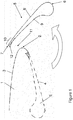
- Figure 1 illustrates an aircraft wing comprising a main ("fixed") wing element 1 having a leading edge 2, an upper aerodynamic surface 3, and a lower aerodynamic surface 4.
- the upper and lower aerodynamic surfaces 3, 4 meet at the leading edge 2.
- a Krueger 5 is mounted to the main wing element 1 for movement between a retracted position (shown in broken line) and a deployed position (shown in full line).
- the leading edge Krueger 5 is a high-lift device deployed at low speed and high incidence to increase the camber and maximum lift coefficient of the wing.
- the Krueger is movable between its deployed and retracted positions by a Krueger actuation mechanism, which has been omitted from Figure 1 for clarity.
- the deployed Krueger 5 has a leading edge 6, a trailing edge 7, an upper aerodynamic surface 8 and a lower aerodynamic surface 9.
- the upper and lower aerodynamic surfaces 8, 9 meet at the leading and trailing edges 6, 7.
- a region of the Krueger adjacent the trailing edge 7 will hereafter be referred to as the trailing edge region 10.
- the retracted Krueger 5 is stowed within the profile of the main wing element 1.
- the Krueger surface 8 forms part of the lower aerodynamic surface 4 of the main wing element 1 when the Krueger is retracted. Accordingly, the Krueger surface 8 is profiled to match the lower aerodynamic surface 4 of the main wing element 1.
- the Krueger 5 rotates forwardly from the lower aerodynamic surface 4 of the main wing element 1 under action of the Krueger actuation mechanism (not shown) pivotally connected at one or more points to the Krueger 5.
- the deployed Krueger 5 forms a slot 11 between the main wing element 1 and the Krueger lower aerodynamic surface 9.
- the Krueger 5 is therefore known as a "slotted Krueger". Airflow through the slot 11 acts to increase circulation around the Krueger which suppresses the leading edge suction pressure peak of the main wing, so improving aerodynamic performance of the wing at high incidence by delaying flow separation.
- the Krueger 5 has a flow deflector 12 on the lower aerodynamic surface 9 in the trailing edge region 10. Without the flow deflector, the gap between the main wing element 1 and the lower aerodynamic surface 9 of the Krueger 5 would be decreasing and then increasing when progressing around from the wing leading edge 2 towards the Krueger trailing edge 7. This decreasing-increasing gap forms a convergent-divergent slot.
- the slot is only convergent such that it maximises the circulation around the Krueger to suppress the leading edge suction peak on the main wing element and provide a high maximum lift coefficient on the wing.
- the slot is convergent-divergent, then the airflow through the slot provides a reduced circulation around the Krueger with the subsequent degradation of the maximum lift coefficient of the wing as a result of an increase of the wing leading edge pressure suction peak.
- the slot 11 geometry is defined, in part, by the angle and location of the deployed Krueger 5 ahead of the wing leading edge 2.
- Kinematic constraints on the Krueger actuation mechanism mean that the slot geometry cannot be optimised as this would result in a more complex, heavier Krueger actuation mechanism design. Instead, the flow deflector 12 acts to reduce, or eliminate the slot divergence.
- the flow diverter 12 is stowed with the Krueger 5 within the profile of the main wing element 1 when the Krueger is retracted. Therefore, the flow deflector 12 does not contribute to cruise drag.
- the flow deflector 12 comprises a small, curved wedge attached to the lower aerodynamic Krueger surface 9 positioned at the trailing edge region 10.
- the flow deflector 12 directs the airflow away from the lower Krueger surface 9 towards the wing upper surface 3 which has the effect of converging the flow in the slot 11 between the wing leading edge 2 and the Krueger trailing edge 7. This can have an aerodynamic benefit of providing an improved circulation of the flow around the Krueger which reduces the wing suction peak pressures and subsequently improves the wing boundary layer.
- the wedge-shaped flow deflector 12 necessarily increases the thickness of the Krueger trailing edge 7. This thick trailing edge creates a thicker wake from the Krueger 5, which undesirably could interfere with the wing boundary layer.
- the design of the of the flow deflector 12 can be optimised to maximise the desirable effects of increased Krueger circulation and minimise the undesirable effects of the thicker Krueger wake.
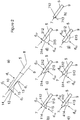
- the wedge-shaped flow deflector 12 is shown in detail in Figure 2a ) and features a tapered front edge 13 blended into the lower aerodynamic Krueger surface 9, and a blunt planar back face 14 coincident with the Krueger trailing edge 7.
- the flow deflector 12 has a concave lower surface 15.
- the minimum profile thickness d 1 for the Krueger 5 occurs just forward (upstream) of the Krueger trailing edge region 10.
- the maximum profile thickness d 2 in the Krueger trailing edge region 10 dictates the Krueger wake thickness. In this embodiment, d 2 is coincident with the Krueger trailing edge 7.
- the flow deflector 12 is a separate part attached to the lower aerodynamic Krueger surface 9, the flow deflector could be integrally formed with the Krueger 5. In this case, the lower aerodynamic Krueger surface 9 would be profiled to form the flow deflector 12.
- Figures 2b) to 2h) illustrate several alternative arrangements for the flow deflector.
- the flow deflector 112 has a wedge-shaped profile and features a tapered front edge 113 blended into the lower aerodynamic Krueger surface 9, and a blunt planar back face 114 extending rearwardly from the Krueger trailing edge 7.
- the flow deflector 112 has a concave lower surface 115.
- the maximum profile thickness d 12 is aft of the Krueger trailing edge 7.
- the flow deflector 212 has a triangular profile and features a planar inclined front face 213 and a planar inclined back face 214 extending to the Krueger trailing edge 7.
- the maximum profile thickness d 22 is forward of the Krueger trailing edge 7.
- the flow deflector 312 features a convex lower surface 315 and a blunt planar back face 314 substantially coincident with the Krueger trailing edge 7.
- the maximum profile thickness d 32 is coincident with the Krueger trailing edge 7.
- the flow deflector 412 features a concave front surface 413, which is blended into the lower aerodynamic Krueger surface 9, and a concave back surface 414, which extends to the Krueger trailing edge 7.
- the maximum profile thickness d 42 is forward of the Krueger trailing edge 7.
- the flow deflector 512 has a triangular profile and features a planar inclined lower surface 515 and a planar inclined back face 514 extending rearwardly from the Krueger trailing edge 7.
- the maximum profile thickness d 52 is aft of the Krueger trailing edge 7.
- the flow deflector 612 has a convex lower surface 615 extending from the lower aerodynamic Krueger surface 9 to the Krueger trailing edge 7.
- the maximum profile thickness d 62 is forward of the Krueger trailing edge 7.
- the flow deflectors 112, 212, 312, 412, 512, and 612 may be formed as separate parts attached to the lower aerodynamic Krueger surface, or may be integrally formed with the Krueger 5.
- the flow deflector 712 is formed as a tab 713 extending downwardly from the lower aerodynamic Krueger surface 9 adjacent the Krueger trailing edge 7.
- the tab 713 creates a region or recirculating air just in front of the tab such that the bulk airflow over the lower aerodynamic Krueger surface 9 is deflected downwardly
- This type of deflector could be fixed or hinged about its base.
- Figure 3a illustrates graphically the convergence criteria of a gap between the main wing element and the deployed Krueger.
- Figure 3b illustrates the graphical plot showing three cases where the gap is measured along a distance S from the leading edge of the main wing to the Krueger lower surface up to its trailing edge.
- a Krueger with a trailing edge flow deflector in accordance with the invention forms a marginally convergent slot, where the trailing edge flow deflector reduces the distance from the Krueger lower surface to the wing leading edge such that it reaches a minimum at the Krueger trailing edge trailing edge C.
- a Krueger with a trailing edge flow deflector in accordance with the invention forms a fully convergent slot, where the distance from the Krueger trailing edge to the wing leading edge C is further reduced to provide a progressive reduction of the gap towards the Krueger trailing edge.
- Case (1) illustrates the sub-optimal condition in which kinematic constraints on the Krueger (without the flow deflector) create a slot gap which decreases and then increases when progressing aft from the leading edge of the main wing element to the Krueger trailing edge. This therefore forms a convergent-divergent slot.
- Case (2) with the flow deflector applied, has a slot gap which decreases when progressing aft from the leading edge of the main wing element towards the Krueger trailing edge to provide a marginally convergent slot.
- This gap could also increase slightly at the Krueger trailing edge but the flow deflector still acts to significantly reduce the slot divergence to provide a beneficial aerodynamic effect.
- the deployed Krueger in accordance with the invention will in most cases have its trailing edge in a higher position relative to the main wing element than would normally be the case. This is due to the under rotation of the Krueger to its deployed position owing to the kinematic constraints. However, this high trailing edge position can have a desirable effect since the Krueger may act as an insect shield for the main wing element. This may be particularly beneficial where the wing is a "laminar wing". Insect debris on the main wing element leading edge can promote turbulent flow and so insect shielding helps maintain laminar flow.
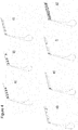
- Figures 4a) to 4h) illustrate examples of three dimensional installations of the flow deflector.
- Figure 4a illustrates a flow deflector having a regular sawtooth shape across the span.
- Figure 4b illustrates a flow deflector having a varying sawtooth shape across the span.
- Figure 4c illustrates a flow deflector having a regular castellation shape across the span.
- Figure 4d illustrates a flow deflector having a varying castellation shape across the span.
- Figure 4e illustrates a flow deflector having a continuous wedge shape across the span.
- Figure 4f illustrates a flow deflector having a continuous wedge shape with one or more intermittent breaks across the span.
- Figure 4g illustrates a flow deflector having a smoothly varying continuous wedge shape across the span.
- Figures 4a) to 4g illustrate examples of three dimensional installations of the flow deflector having either: constant or varying thickness across the Krueger span; castellated or sawtooth shape variation across the Krueger span; discontinuous application across the Krueger span; or any combination of the above.
- the three dimensional variation in the shape of the flow deflector can be adapted to provide a distribution of vortex generators for introducing multiple vortical flows into the slot across the Krueger span. This can improve mixing between the wake from the Krueger trailing edge and the flow through the slot which can reduce the adverse interference between the wake and the wing boundary layer. There is therefore a resultant improvement in the maximum lift of the wing.
Description
- The present invention relates to a Krueger, or leading edge flap, for an aircraft wing.
- A Krueger, or leading edge flap, is a high-lift device deployable from the lower aerodynamic surface of an aerofoil, such as an aircraft wing. When stowed the Krueger trailing edge is disposed at or near the wing leading edge, and a portion of the Krueger device makes up part of the wing lower surface. When deployed the Krueger rotates forwardly from a hinge near the wing leading edge, and the Krueger trailing edge remains adjacent the wing leading edge.
- Whilst the Krueger is functionally similar to a slat when deployed, slats are deployed forwardly from the wing leading edge.
- Leading edge high-lift devices can be either "slotted" or "un-slotted". Slotted means that a gap, or slot, is opened up between the deployed high-lift device and the wing leading edge. Un-slotted means that the deployed high-lift device is sealed to the wing leading edge. Airflow through the slotted gap can improve the maximum lift coefficient of the wing in a high-lift configuration, i.e. with the high-lift device deployed.
- For best performance the gap between the deployed high-lift device and the wing should be convergent. That is to say, the gap between the wing leading edge and the lower aerodynamic surface of the high-lift device should progressively reduce up to the trailing edge of the deployed high-lift device. If the slot is convergent-divergent the circulation around the high-lift device is reduced due to the less than optimal aerodynamic setting.
- A convergent slot can normally be achieved by positioning the deployed device at an appropriate angle and location ahead of the wing leading edge. However, kinematic constraints, particularly for Krueger actuation mechanisms, can limit the positioning of the deployed device and create a convergent-divergent slot. In particular, the available extent of rotation of the Krueger during deployment will affect the angle of the deployed Krueger. Further rotation to an aerodynamically more desirable angle may not be possible without resulting in a more complex, heavier design.
- A Krueger flap is known from
EP1338506 , which is regarded as the closest prior art. - A first aspect of the invention provides a Krueger, or leading edge flap, deployable from a lower aerodynamic surface of an aircraft main wing element so as to form a slot between the Krueger and the main wing element when deployed, the deployed Krueger having a leading edge, a trailing edge and upper and lower aerodynamic surfaces extending between the leading edge and the trailing edge, and a flow deflector which provides an effectively divergent flap profile thickness in the downstream direction at or adjacent the Krueger trailing edge so as to direct airflow away from the lower aerodynamic surface of the deployed Krueger towards an upper aerodynamic surface of the main wing element.
- A further aspect of the invention provides an aircraft wing assembly including a main wing element and a Krueger in accordance with the first aspect.
- The invention is advantageous in that the flow deflector acts to reduce, or eliminate, slot divergence, particularly where this cannot otherwise be achieved due to kinematic constraints. The profile of the upper aerodynamic surface of the Krueger is dictated by the profile of the lower surface of the main wing element, since these must match when the Krueger is retracted. By directing the airflow away from adjacent the trailing edge of the lower aerodynamic surface of the Krueger towards the wing upper surface the flow deflector can reduce, or eliminate the slot divergence.
- The flow deflector may be fixed with respect to the Krueger trailing edge. Preferably, the entire Krueger including the flow deflector is stowed within a profile of the main wing element when the Krueger is retracted. Therefore, the fixed flow deflector does not contribute to cruise drag.
- The lower surface panel of the main wing element from which the Krueger is constructed can be flexible or rigid depending on the design concept of the Krueger. In particular, the Krueger trailing edge may be flexible.
- The flow deflector may be formed as a profiled surface of the Krueger lower aerodynamic surface. The upper and lower Krueger aerodynamic surfaces may be divergent in the downstream direction at or adjacent the Krueger trailing edge.
- Alternatively, the flow deflector may be formed as a profiled component, e.g. a wedge, attached to the Krueger lower aerodynamic surface at or adjacent the Krueger trailing edge. The flow deflector may be detachable from the Krueger lower surface.
- In either case, the flow deflector effectively forms a divergent Krueger profile in the Krueger trailing edge region such that airflow over the lower aerodynamic surface is deflected downwardly towards the upper surface of the main wing element. It is not necessary that the divergent Krueger profile has its thickest part exactly at the Krueger trailing edge. For example, the flow deflector may provide a profile thickness for the Krueger adjacent the Krueger trailing edge that is greater than the Krueger profile thickness forward of the flow deflector.
- In a further alternative example, the flow deflector may be formed as a tab projecting downwardly from the Krueger lower aerodynamic surface at or adjacent the Krueger trailing edge. The tab creates a region or recirculating air just in front of the tab which has the effect of smoothly deflecting the bulk airflow over the lower aerodynamic surface of the Krueger downwardly towards the upper surface of the main wing element.
- The flow deflector at or adjacent the Krueger trailing edge is not limited to a consistent thickness or angle across the span of the Krueger. The thickness may vary progressively across the span or may alternatively be applied in a stepped variation to form a castellated or sawtooth pattern. A stepped variation can act as vortex generators by introducing multiple vortical flows into the slot across the Krueger span. This can improve mixing between the wake from the Krueger trailing edge and the flow through the slot which can reduce the adverse interference between the wake and the wing boundary layer. There is therefore a resultant improvement in the maximum lift of the wing.
- It is known that a thick Krueger trailing edge produces a wake which could disturb the wing boundary layer. The flow deflector has the effect of increasing the Krueger wake thickness. Accordingly, there is a trade off between the positive effect of increasing the circulation around the Krueger to suppress the suction wing peak as a result of improved slot convergence, and disturbance to the wing boundary layer by the interaction of the thickened Krueger wake due to the increased wake thickness caused by the flow deflector. The Krueger/flow deflector design therefore needs to be optimised for maximum aerodynamic performance.
- Integrally forming the flow deflector with the Krueger may provide advantages in terms of reduced maintenance, reduced parts count, reduced production time, improved stiffness and weight saving. However, a detachable flow deflector may provide advantages for ease of removal for repair, testing etc.
- The deployed Krueger, if suitably placed, may act as an insect shield for the main wing element. This would be particularly beneficial where the wing is a "laminar wing", i.e. where the intention is to maintain a laminar boundary layer over a large percentage of the wing at cruise. Insect debris on the wing leading edge can promote turbulent boundary layer flow. The invention is also applicable to conventional, non-laminar, wings.
- The slot, which opens up between the Krueger and the main wing element when the Krueger is deployed, is preferably convergent forward of the flow deflector in the direction of the onset flow. The flow deflector reduces, or eliminates, divergence of the slot adjacent the Krueger trailing edge.
- Embodiments of the invention will now be described with reference to the accompanying drawings, in which:
-
Figure 1 illustrates schematically a section through an aircraft wing with a Krueger shown in its deployed position (full line) and retracted position (broken line); -
Figure 2a ) illustrates the Krueger trailing edge region in detail showing the flow deflector; andFigures 2b) to 2g ) illustrate alternative flow deflector arrangements for the Krueger; -
Figure 3a ) illustrates graphically the convergence criteria of a gap between the main wing element and the deployed Krueger; andFigure 3b ) illustrates the graphical plot showing three cases where the gap is measured along a distance S from the leading edge of the main wing to the Krueger lower surface up to its trailing edge; and -
Figures 4a) to 4g) illustrate examples of three dimensional installation of the flow deflector. -
Figure 1 illustrates an aircraft wing comprising a main ("fixed")wing element 1 having a leadingedge 2, an upperaerodynamic surface 3, and a loweraerodynamic surface 4. The upper and loweraerodynamic surfaces edge 2. AKrueger 5 is mounted to themain wing element 1 for movement between a retracted position (shown in broken line) and a deployed position (shown in full line). Theleading edge Krueger 5 is a high-lift device deployed at low speed and high incidence to increase the camber and maximum lift coefficient of the wing. The Krueger is movable between its deployed and retracted positions by a Krueger actuation mechanism, which has been omitted fromFigure 1 for clarity. - The deployed
Krueger 5 has aleading edge 6, a trailingedge 7, an upperaerodynamic surface 8 and a loweraerodynamic surface 9. The upper and loweraerodynamic surfaces edges edge 7 will hereafter be referred to as the trailingedge region 10. - The retracted
Krueger 5 is stowed within the profile of themain wing element 1. TheKrueger surface 8 forms part of the loweraerodynamic surface 4 of themain wing element 1 when the Krueger is retracted. Accordingly, theKrueger surface 8 is profiled to match the loweraerodynamic surface 4 of themain wing element 1. - The
Krueger 5 rotates forwardly from the loweraerodynamic surface 4 of themain wing element 1 under action of the Krueger actuation mechanism (not shown) pivotally connected at one or more points to theKrueger 5. - The deployed
Krueger 5 forms aslot 11 between themain wing element 1 and the Krueger loweraerodynamic surface 9. TheKrueger 5 is therefore known as a "slotted Krueger". Airflow through theslot 11 acts to increase circulation around the Krueger which suppresses the leading edge suction pressure peak of the main wing, so improving aerodynamic performance of the wing at high incidence by delaying flow separation. - The
Krueger 5 has aflow deflector 12 on the loweraerodynamic surface 9 in the trailingedge region 10. Without the flow deflector, the gap between themain wing element 1 and the loweraerodynamic surface 9 of theKrueger 5 would be decreasing and then increasing when progressing around from thewing leading edge 2 towards theKrueger trailing edge 7. This decreasing-increasing gap forms a convergent-divergent slot. - Ideally, the slot is only convergent such that it maximises the circulation around the Krueger to suppress the leading edge suction peak on the main wing element and provide a high maximum lift coefficient on the wing. However, if the slot is convergent-divergent, then the airflow through the slot provides a reduced circulation around the Krueger with the subsequent degradation of the maximum lift coefficient of the wing as a result of an increase of the wing leading edge pressure suction peak.
- The
slot 11 geometry is defined, in part, by the angle and location of the deployedKrueger 5 ahead of thewing leading edge 2. Kinematic constraints on the Krueger actuation mechanism (not shown) mean that the slot geometry cannot be optimised as this would result in a more complex, heavier Krueger actuation mechanism design. Instead, theflow deflector 12 acts to reduce, or eliminate the slot divergence. - The
flow diverter 12 is stowed with theKrueger 5 within the profile of themain wing element 1 when the Krueger is retracted. Therefore, theflow deflector 12 does not contribute to cruise drag. - The
flow deflector 12 comprises a small, curved wedge attached to the loweraerodynamic Krueger surface 9 positioned at the trailingedge region 10. Theflow deflector 12 directs the airflow away from thelower Krueger surface 9 towards the wingupper surface 3 which has the effect of converging the flow in theslot 11 between thewing leading edge 2 and theKrueger trailing edge 7. This can have an aerodynamic benefit of providing an improved circulation of the flow around the Krueger which reduces the wing suction peak pressures and subsequently improves the wing boundary layer. - The wedge-shaped
flow deflector 12 necessarily increases the thickness of theKrueger trailing edge 7. This thick trailing edge creates a thicker wake from theKrueger 5, which undesirably could interfere with the wing boundary layer. - The design of the of the
flow deflector 12 can be optimised to maximise the desirable effects of increased Krueger circulation and minimise the undesirable effects of the thicker Krueger wake. - The wedge-shaped
flow deflector 12 is shown in detail inFigure 2a ) and features a taperedfront edge 13 blended into the loweraerodynamic Krueger surface 9, and a blunt planarback face 14 coincident with theKrueger trailing edge 7. Theflow deflector 12 has a concavelower surface 15. The minimum profile thickness d1 for theKrueger 5 occurs just forward (upstream) of the Krueger trailingedge region 10. The maximum profile thickness d2 in the Krueger trailingedge region 10 dictates the Krueger wake thickness. In this embodiment, d2 is coincident with theKrueger trailing edge 7. - Whilst in the embodiment described above the
flow deflector 12 is a separate part attached to the loweraerodynamic Krueger surface 9, the flow deflector could be integrally formed with theKrueger 5. In this case, the loweraerodynamic Krueger surface 9 would be profiled to form theflow deflector 12. -
Figures 2b) to 2h) illustrate several alternative arrangements for the flow deflector. InFigure 2b ) theflow deflector 112 has a wedge-shaped profile and features a taperedfront edge 113 blended into the loweraerodynamic Krueger surface 9, and a blunt planarback face 114 extending rearwardly from theKrueger trailing edge 7. Theflow deflector 112 has a concavelower surface 115. The maximum profile thickness d12 is aft of theKrueger trailing edge 7. - In
Figure 2c ) theflow deflector 212 has a triangular profile and features a planar inclinedfront face 213 and a planarinclined back face 214 extending to theKrueger trailing edge 7. The maximum profile thickness d22 is forward of theKrueger trailing edge 7. - In
Figure 2d ) theflow deflector 312 features a convexlower surface 315 and a blunt planarback face 314 substantially coincident with theKrueger trailing edge 7. The maximum profile thickness d32 is coincident with theKrueger trailing edge 7. - In
Figure 2e ) theflow deflector 412 features a concavefront surface 413, which is blended into the loweraerodynamic Krueger surface 9, and aconcave back surface 414, which extends to theKrueger trailing edge 7. The maximum profile thickness d42 is forward of theKrueger trailing edge 7. - In
Figure 2f ) theflow deflector 512 has a triangular profile and features a planar inclined lower surface 515 and a planarinclined back face 514 extending rearwardly from theKrueger trailing edge 7. The maximum profile thickness d52 is aft of theKrueger trailing edge 7. - In
Figure 2g ) theflow deflector 612 has a convexlower surface 615 extending from the loweraerodynamic Krueger surface 9 to theKrueger trailing edge 7. The maximum profile thickness d62 is forward of theKrueger trailing edge 7. - In each of the embodiments described above with reference to
Figures 2b ) to g) theflow deflectors Krueger 5. - In
Figure 2h ) theflow deflector 712 is formed as atab 713 extending downwardly from the loweraerodynamic Krueger surface 9 adjacent theKrueger trailing edge 7. Thetab 713 creates a region or recirculating air just in front of the tab such that the bulk airflow over the loweraerodynamic Krueger surface 9 is deflected downwardly This type of deflector could be fixed or hinged about its base. -
Figure 3a ) illustrates graphically the convergence criteria of a gap between the main wing element and the deployed Krueger.Figure 3b ) illustrates the graphical plot showing three cases where the gap is measured along a distance S from the leading edge of the main wing to the Krueger lower surface up to its trailing edge. - For case (1) a Krueger without the flow deflector (as shown in
Figure 3a )) and with kinematic constraints which impose a divergent slot, where B (the minimum distance from the Krueger lower surface to the wing leading edge) is greater than C (the distance from the Krueger trailing edge to the wing leading edge). - For case (2) a Krueger with a trailing edge flow deflector in accordance with the invention forms a marginally convergent slot, where the trailing edge flow deflector reduces the distance from the Krueger lower surface to the wing leading edge such that it reaches a minimum at the Krueger trailing edge trailing edge C.
- For case (3) a Krueger with a trailing edge flow deflector in accordance with the invention (as shown in
Figure 1 ) forms a fully convergent slot, where the distance from the Krueger trailing edge to the wing leading edge C is further reduced to provide a progressive reduction of the gap towards the Krueger trailing edge. - The plots for cases (2) and (3) indicate how the trailing edge flow deflector can be applied to improve the convergence of the slot.
- As can be seen from case (3) the gap between the deployed Krueger and the main wing element would ideally decrease progressively aft from the leading edge of the main wing element all the way to the Krueger trailing edge - an "ideal slot shape". However, with kinematic constraints on the position and angle of the deployed Krueger this can be impossible to achieve. These kinematic constraints mean the deployed Krueger cannot be positioned in the optimal position to achieve the ideal slot shape without the trailing edge flow deflector.
- Case (1) illustrates the sub-optimal condition in which kinematic constraints on the Krueger (without the flow deflector) create a slot gap which decreases and then increases when progressing aft from the leading edge of the main wing element to the Krueger trailing edge. This therefore forms a convergent-divergent slot.
- Case (2), with the flow deflector applied, has a slot gap which decreases when progressing aft from the leading edge of the main wing element towards the Krueger trailing edge to provide a marginally convergent slot. This gap could also increase slightly at the Krueger trailing edge but the flow deflector still acts to significantly reduce the slot divergence to provide a beneficial aerodynamic effect.
- It is possible to eliminate slot divergence entirely with the flow deflector if the slot divergence for a Krueger is sufficiently small, as shown in case (3).
- The deployed Krueger in accordance with the invention will in most cases have its trailing edge in a higher position relative to the main wing element than would normally be the case. This is due to the under rotation of the Krueger to its deployed position owing to the kinematic constraints. However, this high trailing edge position can have a desirable effect since the Krueger may act as an insect shield for the main wing element. This may be particularly beneficial where the wing is a "laminar wing". Insect debris on the main wing element leading edge can promote turbulent flow and so insect shielding helps maintain laminar flow.
-
Figures 4a) to 4h) illustrate examples of three dimensional installations of the flow deflector.Figure 4a ) illustrates a flow deflector having a regular sawtooth shape across the span.Figure 4b ) illustrates a flow deflector having a varying sawtooth shape across the span.Figure 4c ) illustrates a flow deflector having a regular castellation shape across the span.Figure 4d ) illustrates a flow deflector having a varying castellation shape across the span.Figure 4e ) illustrates a flow deflector having a continuous wedge shape across the span.Figure 4f ) illustrates a flow deflector having a continuous wedge shape with one or more intermittent breaks across the span. Finally,Figure 4g ) illustrates a flow deflector having a smoothly varying continuous wedge shape across the span. - Broadly,
Figures 4a) to 4g ) illustrate examples of three dimensional installations of the flow deflector having either: constant or varying thickness across the Krueger span; castellated or sawtooth shape variation across the Krueger span; discontinuous application across the Krueger span; or any combination of the above. - The three dimensional variation in the shape of the flow deflector can be adapted to provide a distribution of vortex generators for introducing multiple vortical flows into the slot across the Krueger span. This can improve mixing between the wake from the Krueger trailing edge and the flow through the slot which can reduce the adverse interference between the wake and the wing boundary layer. There is therefore a resultant improvement in the maximum lift of the wing.
- Although the invention has been described above with reference to one or more preferred embodiments, it will be appreciated that various changes or modifications may be made without departing from the scope of the invention as defined in the appended claims.
Claims (17)
- A Krueger flap (5), deployable from a lower aerodynamic surface of an aircraft main wing element (1) so as to form a slot between the Krueger and the main wing element when deployed, the deployed Krueger having a leading edge (6), a trailing edge (7) and upper and lower aerodynamic surfaces extending between the leading edge and the trailing edge, and a flow deflector (12) so as to direct airflow away from the lower aerodynamic surface of the deployed Krueger towards an upper aerodynamic surface of the main wing element, characterized in that the flow deflector (12) provides an effectively divergent flap profile thickness in the downstream direction at or adjacent the Krueger trailing edge.
- A Krueger according to claim 1, wherein the flow deflector is fixed with respect to the Krueger trailing edge.
- A Krueger according to claim 1 or 2, wherein the Krueger trailing edge is flexible.
- A Krueger according to any preceding claim, wherein the flow deflector is formed as a profiled surface of the Krueger lower aerodynamic surface.
- A Krueger according to claim 4, wherein the upper and lower Krueger aerodynamic surfaces are divergent in the downstream direction at or adjacent the Krueger trailing edge.
- A Krueger according to any of claims 1 to 3, wherein the flow deflector is formed as a profiled component attached to the Krueger lower aerodynamic surface at or adjacent the Krueger trailing edge.
- A Krueger according to claim 6, wherein the flow deflector is detachable.
- A Krueger according to any of claim 1 to 3, wherein the flow deflector is formed as a tab projecting downwardly from the Krueger lower aerodynamic surface at or adjacent the Krueger trailing edge.
- A Krueger according to any preceding claim, wherein the flow deflector provides a profile thickness for the Krueger at or adjacent the Krueger trailing edge that is greater than the Krueger profile thickness forward of the flow deflector.
- A Krueger according to any preceding claim, wherein the flow deflector has a varying thickness or shape across the span.
- A Krueger according to any preceding claim, wherein the flow deflector is discontinuous across the span.
- A Krueger according to any preceding claim, wherein the flow deflector has a sawtooth and/or castellated profile adapted to generate vertical flow into a mixing region between the main wing element boundary layer and the freestream flow.
- An aircraft wing assembly including a main wing element and a Krueger in accordance with any preceding claim.
- An aircraft wing according to claim 13, wherein the deployed Krueger provides an insect shield for the main wing element.
- An aircraft wing according to claim 13 or 14, wherein a slot, which opens up between the Krueger and the main wing element when the Krueger is deployed, is convergent forward of flow deflector.
- An aircraft wing according to claim 15, wherein the flow deflector reduces, or eliminates, divergence of the slot at or adjacent the Krueger trailing edge.
- An aircraft wing according to any of claims 13 to 16, wherein the entire Krueger including the flow deflector is stowed within a profile of the main wing element when the Krueger is retracted.
Applications Claiming Priority (1)
| Application Number | Priority Date | Filing Date | Title |
|---|---|---|---|
| GBGB1018176.6A GB201018176D0 (en) | 2010-10-28 | 2010-10-28 | Krueger |
Publications (3)
| Publication Number | Publication Date |
|---|---|
| EP2447152A2 EP2447152A2 (en) | 2012-05-02 |
| EP2447152A3 EP2447152A3 (en) | 2016-03-16 |
| EP2447152B1 true EP2447152B1 (en) | 2017-09-06 |
Family
ID=43365627
Family Applications (1)
| Application Number | Title | Priority Date | Filing Date |
|---|---|---|---|
| EP11184270.4A Not-in-force EP2447152B1 (en) | 2010-10-28 | 2011-10-07 | Krueger flap |
Country Status (3)
| Country | Link |
|---|---|
| US (1) | US8657239B2 (en) |
| EP (1) | EP2447152B1 (en) |
| GB (1) | GB201018176D0 (en) |
Families Citing this family (3)
| Publication number | Priority date | Publication date | Assignee | Title |
|---|---|---|---|---|
| DE102010014792A1 (en) * | 2010-04-13 | 2011-10-13 | Airbus Operations Gmbh | High-lift system for an aircraft |
| DE102011018906A1 (en) * | 2011-04-28 | 2012-10-31 | Airbus Operations Gmbh | High lift system for an aircraft and method for influencing the high lift characteristics of an aircraft |
| US20170152018A1 (en) | 2015-12-01 | 2017-06-01 | The Boeing Company | Leading edge high-lift device |
Family Cites Families (28)
| Publication number | Priority date | Publication date | Assignee | Title |
|---|---|---|---|---|
| US3578264A (en) * | 1968-07-09 | 1971-05-11 | Battelle Development Corp | Boundary layer control of flow separation and heat exchange |
| US4354648A (en) * | 1980-02-06 | 1982-10-19 | Gates Learjet Corporation | Airstream modification device for airfoils |
| US5058837A (en) * | 1989-04-07 | 1991-10-22 | Wheeler Gary O | Low drag vortex generators |
| GB2260521B (en) | 1991-10-19 | 1995-03-22 | British Aerospace | An aircraft wing leading edge arrangement |
| US5158252A (en) | 1991-10-24 | 1992-10-27 | The Boeing Company | Three-position variable camber Krueger leading edge flap |
| US5598990A (en) * | 1994-12-15 | 1997-02-04 | University Of Kansas Center For Research Inc. | Supersonic vortex generator |
| CA2168003C (en) * | 1996-02-02 | 2001-04-17 | Carl W. Millard | Large aircraft critical surface covers |
| US6598834B2 (en) * | 2000-02-14 | 2003-07-29 | Aerotech Services Inc. | Method for reducing fuel consumption in aircraft |
| DE10019185C2 (en) * | 2000-04-17 | 2003-06-05 | Airbus Gmbh | Arrangement for aerodynamic noise reduction of slats in a commercial aircraft |
| US6435458B1 (en) * | 2001-02-12 | 2002-08-20 | The Boeing Company | Tailored wing assembly for an aircraft moveable slat system |
| EP1338506A1 (en) * | 2002-02-15 | 2003-08-27 | Fairchild Dornier GmbH | Airplane wing with slat and Krueger flap |
| US7270305B2 (en) * | 2004-06-15 | 2007-09-18 | The Boeing Company | Aircraft leading edge apparatuses and corresponding methods |
| DE102004049504A1 (en) * | 2004-10-11 | 2006-04-13 | Airbus Deutschland Gmbh | Wing for aircraft has a rear auxiliary lift flap coupled to main wing and able to lie against main wing in retracted position and form air gap with it when extended |
| DE102004056537B4 (en) * | 2004-11-23 | 2010-09-09 | Eads Deutschland Gmbh | Arrangement for reducing the aerodynamic noise on an additional wing of an aircraft |
| US7322547B2 (en) * | 2005-01-31 | 2008-01-29 | The Boeing Company | Aerospace vehicle leading edge slat devices and corresponding methods |
| US7578484B2 (en) * | 2006-06-14 | 2009-08-25 | The Boeing Company | Link mechanisms for gapped rigid krueger flaps, and associated systems and methods |
| DE102006053259A1 (en) * | 2006-11-11 | 2008-05-21 | Airbus Deutschland Gmbh | High-lift system on the wing of an aircraft and method for its operation |
| DE102007061590A1 (en) * | 2007-12-20 | 2009-08-13 | Airbus Deutschland Gmbh | High lift system for an aircraft with a main wing and an adjustable slat |
| DE102008033005A1 (en) * | 2008-07-14 | 2010-03-18 | Airbus Deutschland Gmbh | Aerodynamic flap and wings |
| ITTO20080566A1 (en) * | 2008-07-23 | 2010-01-24 | Alenia Aeronautica Spa | ACTUATOR DEVICE BASED ON ALLOY OF SHAPE MEMORY AND FLAP GROUP FLYWHEEL EQUIPPED WITH SUCH AN ACTUATOR DEVICE |
| US8226048B2 (en) * | 2008-12-09 | 2012-07-24 | The Boeing Company | Link mechanisms, including Stephenson II link mechanisms for multi-position flaps and associated systems and methods |
| GB0908354D0 (en) * | 2009-05-15 | 2009-06-24 | Airbus Uk Ltd | Blade seal |
| GB0908751D0 (en) * | 2009-05-21 | 2009-07-01 | Airbus Uk Ltd | Slot seal |
| GB0911012D0 (en) * | 2009-06-25 | 2009-08-12 | Airbus Operations Ltd | Cross-bleed dam |
| US8210482B2 (en) * | 2009-10-27 | 2012-07-03 | Lockheed Martin Corporation | Prismatic-shaped vortex generators |
| DE102009057340A1 (en) * | 2009-12-07 | 2011-06-09 | Airbus Operations Gmbh | High lift system for an aircraft, method of moving a lift flap, and aircraft with a high lift system |
| DE102010026619B4 (en) * | 2010-07-09 | 2018-11-15 | Airbus Operations Gmbh | Slat with flexible trailing edge |
| US8573541B2 (en) * | 2010-09-13 | 2013-11-05 | John Sullivan | Wavy airfoil |
-
2010
- 2010-10-28 GB GBGB1018176.6A patent/GB201018176D0/en not_active Ceased
-
2011
- 2011-10-07 EP EP11184270.4A patent/EP2447152B1/en not_active Not-in-force
- 2011-10-24 US US13/279,642 patent/US8657239B2/en active Active
Non-Patent Citations (1)
| Title |
|---|
| None * |
Also Published As
| Publication number | Publication date |
|---|---|
| US20120104180A1 (en) | 2012-05-03 |
| EP2447152A3 (en) | 2016-03-16 |
| GB201018176D0 (en) | 2010-12-08 |
| US8657239B2 (en) | 2014-02-25 |
| EP2447152A2 (en) | 2012-05-02 |
Similar Documents
| Publication | Publication Date | Title |
|---|---|---|
| US7900868B2 (en) | Noise-shielding wing configuration | |
| EP2167380B1 (en) | Engine nacelle of an aircraft comprising a vortex generator arrangement | |
| US4702441A (en) | Aircraft wing stall control device and method | |
| CA2783129C (en) | High lift system for an aircraft, method for displcing a lift flap and aircraft with a high lift system | |
| US6364254B1 (en) | Aircraft airfoil with close-mounted engine and leading edge high lift system | |
| EP1755946B1 (en) | High-lift device for an aircraft | |
| US8231084B2 (en) | Aircraft wing | |
| US20110114795A1 (en) | Aerodynamic Flap and Wing | |
| KR20140049966A (en) | Aircraft with improved aerodynamic performance | |
| EP2447152B1 (en) | Krueger flap | |
| CA2719163C (en) | Improved slat configuration for fixed-wing aircraft | |
| US9481447B2 (en) | Aircraft wing with slotted high lift system | |
| US9440729B2 (en) | High-lift-device, wing, and noise reduction device for high-lift-device | |
| EP3647183B1 (en) | Aerodynamic structure for aircraft wing | |
| EP2479106A2 (en) | Leading edge device for an aircraft | |
| CN110539882B (en) | Method and device for optimizing flow at junction of leading edge bending flap and leading edge slat | |
| WO2022249758A1 (en) | Front edge high lift device, wing, aircraft, and buffer member | |
| US20110044812A1 (en) | Airfoil with flow deflector | |
| RU2575738C2 (en) | Aircraft with perfected aerodynamic characteristics |
Legal Events
| Date | Code | Title | Description |
|---|---|---|---|
| PUAI | Public reference made under article 153(3) epc to a published international application that has entered the european phase |
Free format text: ORIGINAL CODE: 0009012 |
|
| AK | Designated contracting states |
Kind code of ref document: A2 Designated state(s): AL AT BE BG CH CY CZ DE DK EE ES FI FR GB GR HR HU IE IS IT LI LT LU LV MC MK MT NL NO PL PT RO RS SE SI SK SM TR |
|
| AX | Request for extension of the european patent |
Extension state: BA ME |
|
| PUAL | Search report despatched |
Free format text: ORIGINAL CODE: 0009013 |
|
| AK | Designated contracting states |
Kind code of ref document: A3 Designated state(s): AL AT BE BG CH CY CZ DE DK EE ES FI FR GB GR HR HU IE IS IT LI LT LU LV MC MK MT NL NO PL PT RO RS SE SI SK SM TR |
|
| AX | Request for extension of the european patent |
Extension state: BA ME |
|
| RIC1 | Information provided on ipc code assigned before grant |
Ipc: B64C 9/14 20060101ALN20160208BHEP Ipc: B64C 9/24 20060101AFI20160208BHEP |
|
| 17P | Request for examination filed |
Effective date: 20160916 |
|
| RBV | Designated contracting states (corrected) |
Designated state(s): AL AT BE BG CH CY CZ DE DK EE ES FI FR GB GR HR HU IE IS IT LI LT LU LV MC MK MT NL NO PL PT RO RS SE SI SK SM TR |
|
| GRAP | Despatch of communication of intention to grant a patent |
Free format text: ORIGINAL CODE: EPIDOSNIGR1 |
|
| GRAJ | Information related to disapproval of communication of intention to grant by the applicant or resumption of examination proceedings by the epo deleted |
Free format text: ORIGINAL CODE: EPIDOSDIGR1 |
|
| RIC1 | Information provided on ipc code assigned before grant |
Ipc: B64C 9/14 20060101ALN20161007BHEP Ipc: B64C 9/24 20060101AFI20161007BHEP |
|
| INTG | Intention to grant announced |
Effective date: 20161031 |
|
| INTC | Intention to grant announced (deleted) | ||
| 17Q | First examination report despatched |
Effective date: 20161128 |
|
| RIC1 | Information provided on ipc code assigned before grant |
Ipc: B64C 9/14 20060101ALN20170201BHEP Ipc: B64C 9/24 20060101AFI20170201BHEP |
|
| GRAP | Despatch of communication of intention to grant a patent |
Free format text: ORIGINAL CODE: EPIDOSNIGR1 |
|
| INTG | Intention to grant announced |
Effective date: 20170406 |
|
| GRAS | Grant fee paid |
Free format text: ORIGINAL CODE: EPIDOSNIGR3 |
|
| GRAA | (expected) grant |
Free format text: ORIGINAL CODE: 0009210 |
|
| AK | Designated contracting states |
Kind code of ref document: B1 Designated state(s): AL AT BE BG CH CY CZ DE DK EE ES FI FR GB GR HR HU IE IS IT LI LT LU LV MC MK MT NL NO PL PT RO RS SE SI SK SM TR |
|
| REG | Reference to a national code |
Ref country code: GB Ref legal event code: FG4D |
|
| REG | Reference to a national code |
Ref country code: CH Ref legal event code: EP Ref country code: AT Ref legal event code: REF Ref document number: 925577 Country of ref document: AT Kind code of ref document: T Effective date: 20170915 |
|
| REG | Reference to a national code |
Ref country code: IE Ref legal event code: FG4D |
|
| REG | Reference to a national code |
Ref country code: DE Ref legal event code: R096 Ref document number: 602011041244 Country of ref document: DE |
|
| REG | Reference to a national code |
Ref country code: FR Ref legal event code: PLFP Year of fee payment: 7 |
|
| REG | Reference to a national code |
Ref country code: NL Ref legal event code: MP Effective date: 20170906 |
|
| REG | Reference to a national code |
Ref country code: LT Ref legal event code: MG4D |
|
| PG25 | Lapsed in a contracting state [announced via postgrant information from national office to epo] |
Ref country code: SE Free format text: LAPSE BECAUSE OF FAILURE TO SUBMIT A TRANSLATION OF THE DESCRIPTION OR TO PAY THE FEE WITHIN THE PRESCRIBED TIME-LIMIT Effective date: 20170906 Ref country code: HR Free format text: LAPSE BECAUSE OF FAILURE TO SUBMIT A TRANSLATION OF THE DESCRIPTION OR TO PAY THE FEE WITHIN THE PRESCRIBED TIME-LIMIT Effective date: 20170906 Ref country code: LT Free format text: LAPSE BECAUSE OF FAILURE TO SUBMIT A TRANSLATION OF THE DESCRIPTION OR TO PAY THE FEE WITHIN THE PRESCRIBED TIME-LIMIT Effective date: 20170906 Ref country code: FI Free format text: LAPSE BECAUSE OF FAILURE TO SUBMIT A TRANSLATION OF THE DESCRIPTION OR TO PAY THE FEE WITHIN THE PRESCRIBED TIME-LIMIT Effective date: 20170906 Ref country code: NO Free format text: LAPSE BECAUSE OF FAILURE TO SUBMIT A TRANSLATION OF THE DESCRIPTION OR TO PAY THE FEE WITHIN THE PRESCRIBED TIME-LIMIT Effective date: 20171206 |
|
| REG | Reference to a national code |
Ref country code: AT Ref legal event code: MK05 Ref document number: 925577 Country of ref document: AT Kind code of ref document: T Effective date: 20170906 |
|
| PG25 | Lapsed in a contracting state [announced via postgrant information from national office to epo] |
Ref country code: BG Free format text: LAPSE BECAUSE OF FAILURE TO SUBMIT A TRANSLATION OF THE DESCRIPTION OR TO PAY THE FEE WITHIN THE PRESCRIBED TIME-LIMIT Effective date: 20171206 Ref country code: ES Free format text: LAPSE BECAUSE OF FAILURE TO SUBMIT A TRANSLATION OF THE DESCRIPTION OR TO PAY THE FEE WITHIN THE PRESCRIBED TIME-LIMIT Effective date: 20170906 Ref country code: GR Free format text: LAPSE BECAUSE OF FAILURE TO SUBMIT A TRANSLATION OF THE DESCRIPTION OR TO PAY THE FEE WITHIN THE PRESCRIBED TIME-LIMIT Effective date: 20171207 Ref country code: RS Free format text: LAPSE BECAUSE OF FAILURE TO SUBMIT A TRANSLATION OF THE DESCRIPTION OR TO PAY THE FEE WITHIN THE PRESCRIBED TIME-LIMIT Effective date: 20170906 Ref country code: LV Free format text: LAPSE BECAUSE OF FAILURE TO SUBMIT A TRANSLATION OF THE DESCRIPTION OR TO PAY THE FEE WITHIN THE PRESCRIBED TIME-LIMIT Effective date: 20170906 |
|
| PG25 | Lapsed in a contracting state [announced via postgrant information from national office to epo] |
Ref country code: NL Free format text: LAPSE BECAUSE OF FAILURE TO SUBMIT A TRANSLATION OF THE DESCRIPTION OR TO PAY THE FEE WITHIN THE PRESCRIBED TIME-LIMIT Effective date: 20170906 |
|
| PG25 | Lapsed in a contracting state [announced via postgrant information from national office to epo] |
Ref country code: PL Free format text: LAPSE BECAUSE OF FAILURE TO SUBMIT A TRANSLATION OF THE DESCRIPTION OR TO PAY THE FEE WITHIN THE PRESCRIBED TIME-LIMIT Effective date: 20170906 Ref country code: RO Free format text: LAPSE BECAUSE OF FAILURE TO SUBMIT A TRANSLATION OF THE DESCRIPTION OR TO PAY THE FEE WITHIN THE PRESCRIBED TIME-LIMIT Effective date: 20170906 Ref country code: CZ Free format text: LAPSE BECAUSE OF FAILURE TO SUBMIT A TRANSLATION OF THE DESCRIPTION OR TO PAY THE FEE WITHIN THE PRESCRIBED TIME-LIMIT Effective date: 20170906 |
|
| PG25 | Lapsed in a contracting state [announced via postgrant information from national office to epo] |
Ref country code: IS Free format text: LAPSE BECAUSE OF FAILURE TO SUBMIT A TRANSLATION OF THE DESCRIPTION OR TO PAY THE FEE WITHIN THE PRESCRIBED TIME-LIMIT Effective date: 20180106 Ref country code: AT Free format text: LAPSE BECAUSE OF FAILURE TO SUBMIT A TRANSLATION OF THE DESCRIPTION OR TO PAY THE FEE WITHIN THE PRESCRIBED TIME-LIMIT Effective date: 20170906 Ref country code: SM Free format text: LAPSE BECAUSE OF FAILURE TO SUBMIT A TRANSLATION OF THE DESCRIPTION OR TO PAY THE FEE WITHIN THE PRESCRIBED TIME-LIMIT Effective date: 20170906 Ref country code: SK Free format text: LAPSE BECAUSE OF FAILURE TO SUBMIT A TRANSLATION OF THE DESCRIPTION OR TO PAY THE FEE WITHIN THE PRESCRIBED TIME-LIMIT Effective date: 20170906 Ref country code: IT Free format text: LAPSE BECAUSE OF FAILURE TO SUBMIT A TRANSLATION OF THE DESCRIPTION OR TO PAY THE FEE WITHIN THE PRESCRIBED TIME-LIMIT Effective date: 20170906 Ref country code: EE Free format text: LAPSE BECAUSE OF FAILURE TO SUBMIT A TRANSLATION OF THE DESCRIPTION OR TO PAY THE FEE WITHIN THE PRESCRIBED TIME-LIMIT Effective date: 20170906 |
|
| REG | Reference to a national code |
Ref country code: CH Ref legal event code: PL |
|
| REG | Reference to a national code |
Ref country code: DE Ref legal event code: R097 Ref document number: 602011041244 Country of ref document: DE |
|
| PG25 | Lapsed in a contracting state [announced via postgrant information from national office to epo] |
Ref country code: MC Free format text: LAPSE BECAUSE OF FAILURE TO SUBMIT A TRANSLATION OF THE DESCRIPTION OR TO PAY THE FEE WITHIN THE PRESCRIBED TIME-LIMIT Effective date: 20170906 |
|
| PLBE | No opposition filed within time limit |
Free format text: ORIGINAL CODE: 0009261 |
|
| STAA | Information on the status of an ep patent application or granted ep patent |
Free format text: STATUS: NO OPPOSITION FILED WITHIN TIME LIMIT |
|
| REG | Reference to a national code |
Ref country code: IE Ref legal event code: MM4A |
|
| PG25 | Lapsed in a contracting state [announced via postgrant information from national office to epo] |
Ref country code: LI Free format text: LAPSE BECAUSE OF NON-PAYMENT OF DUE FEES Effective date: 20171031 Ref country code: DK Free format text: LAPSE BECAUSE OF FAILURE TO SUBMIT A TRANSLATION OF THE DESCRIPTION OR TO PAY THE FEE WITHIN THE PRESCRIBED TIME-LIMIT Effective date: 20170906 Ref country code: LU Free format text: LAPSE BECAUSE OF NON-PAYMENT OF DUE FEES Effective date: 20171007 Ref country code: CH Free format text: LAPSE BECAUSE OF NON-PAYMENT OF DUE FEES Effective date: 20171031 |
|
| 26N | No opposition filed |
Effective date: 20180607 |
|
| REG | Reference to a national code |
Ref country code: BE Ref legal event code: MM Effective date: 20171031 |
|
| PG25 | Lapsed in a contracting state [announced via postgrant information from national office to epo] |
Ref country code: BE Free format text: LAPSE BECAUSE OF NON-PAYMENT OF DUE FEES Effective date: 20171031 Ref country code: SI Free format text: LAPSE BECAUSE OF FAILURE TO SUBMIT A TRANSLATION OF THE DESCRIPTION OR TO PAY THE FEE WITHIN THE PRESCRIBED TIME-LIMIT Effective date: 20170906 |
|
| PG25 | Lapsed in a contracting state [announced via postgrant information from national office to epo] |
Ref country code: MT Free format text: LAPSE BECAUSE OF NON-PAYMENT OF DUE FEES Effective date: 20171007 |
|
| REG | Reference to a national code |
Ref country code: FR Ref legal event code: PLFP Year of fee payment: 8 |
|
| PG25 | Lapsed in a contracting state [announced via postgrant information from national office to epo] |
Ref country code: IE Free format text: LAPSE BECAUSE OF NON-PAYMENT OF DUE FEES Effective date: 20171007 |
|
| PG25 | Lapsed in a contracting state [announced via postgrant information from national office to epo] |
Ref country code: HU Free format text: LAPSE BECAUSE OF FAILURE TO SUBMIT A TRANSLATION OF THE DESCRIPTION OR TO PAY THE FEE WITHIN THE PRESCRIBED TIME-LIMIT; INVALID AB INITIO Effective date: 20111007 |
|
| PG25 | Lapsed in a contracting state [announced via postgrant information from national office to epo] |
Ref country code: CY Free format text: LAPSE BECAUSE OF NON-PAYMENT OF DUE FEES Effective date: 20170906 |
|
| PG25 | Lapsed in a contracting state [announced via postgrant information from national office to epo] |
Ref country code: MK Free format text: LAPSE BECAUSE OF FAILURE TO SUBMIT A TRANSLATION OF THE DESCRIPTION OR TO PAY THE FEE WITHIN THE PRESCRIBED TIME-LIMIT Effective date: 20170906 |
|
| PG25 | Lapsed in a contracting state [announced via postgrant information from national office to epo] |
Ref country code: TR Free format text: LAPSE BECAUSE OF FAILURE TO SUBMIT A TRANSLATION OF THE DESCRIPTION OR TO PAY THE FEE WITHIN THE PRESCRIBED TIME-LIMIT Effective date: 20170906 |
|
| PG25 | Lapsed in a contracting state [announced via postgrant information from national office to epo] |
Ref country code: PT Free format text: LAPSE BECAUSE OF FAILURE TO SUBMIT A TRANSLATION OF THE DESCRIPTION OR TO PAY THE FEE WITHIN THE PRESCRIBED TIME-LIMIT Effective date: 20170906 |
|
| PG25 | Lapsed in a contracting state [announced via postgrant information from national office to epo] |
Ref country code: AL Free format text: LAPSE BECAUSE OF FAILURE TO SUBMIT A TRANSLATION OF THE DESCRIPTION OR TO PAY THE FEE WITHIN THE PRESCRIBED TIME-LIMIT Effective date: 20170906 |
|
| PGFP | Annual fee paid to national office [announced via postgrant information from national office to epo] |
Ref country code: GB Payment date: 20211022 Year of fee payment: 11 Ref country code: DE Payment date: 20211020 Year of fee payment: 11 |
|
| PGFP | Annual fee paid to national office [announced via postgrant information from national office to epo] |
Ref country code: FR Payment date: 20211022 Year of fee payment: 11 |
|
| REG | Reference to a national code |
Ref country code: DE Ref legal event code: R119 Ref document number: 602011041244 Country of ref document: DE |
|
| GBPC | Gb: european patent ceased through non-payment of renewal fee |
Effective date: 20221007 |
|
| PG25 | Lapsed in a contracting state [announced via postgrant information from national office to epo] |
Ref country code: FR Free format text: LAPSE BECAUSE OF NON-PAYMENT OF DUE FEES Effective date: 20221031 Ref country code: DE Free format text: LAPSE BECAUSE OF NON-PAYMENT OF DUE FEES Effective date: 20230503 |
|
| PG25 | Lapsed in a contracting state [announced via postgrant information from national office to epo] |
Ref country code: GB Free format text: LAPSE BECAUSE OF NON-PAYMENT OF DUE FEES Effective date: 20221007 |