EP2339174A1 - System for triggering an emergency system of wind turbine - Google Patents
System for triggering an emergency system of wind turbine Download PDFInfo
- Publication number
- EP2339174A1 EP2339174A1 EP09015864A EP09015864A EP2339174A1 EP 2339174 A1 EP2339174 A1 EP 2339174A1 EP 09015864 A EP09015864 A EP 09015864A EP 09015864 A EP09015864 A EP 09015864A EP 2339174 A1 EP2339174 A1 EP 2339174A1
- Authority
- EP
- European Patent Office
- Prior art keywords
- triggering
- sensor
- wind turbine
- rotor
- rotational speed
- Prior art date
- Legal status (The legal status is an assumption and is not a legal conclusion. Google has not performed a legal analysis and makes no representation as to the accuracy of the status listed.)
- Withdrawn
Links
- 230000001133 acceleration Effects 0.000 claims abstract description 21
- 238000000034 method Methods 0.000 claims abstract description 16
- 238000004590 computer program Methods 0.000 claims abstract description 14
- 230000001939 inductive effect Effects 0.000 claims description 6
- 230000005484 gravity Effects 0.000 claims description 4
- 238000001514 detection method Methods 0.000 claims description 3
- 241001248035 Trigonidiinae Species 0.000 description 7
- 238000005259 measurement Methods 0.000 description 6
- 238000012544 monitoring process Methods 0.000 description 6
- 230000003213 activating effect Effects 0.000 description 5
- 238000004891 communication Methods 0.000 description 4
- 230000006870 function Effects 0.000 description 2
- 238000013459 approach Methods 0.000 description 1
- 230000001419 dependent effect Effects 0.000 description 1
Images
Classifications
-
- F—MECHANICAL ENGINEERING; LIGHTING; HEATING; WEAPONS; BLASTING
- F03—MACHINES OR ENGINES FOR LIQUIDS; WIND, SPRING, OR WEIGHT MOTORS; PRODUCING MECHANICAL POWER OR A REACTIVE PROPULSIVE THRUST, NOT OTHERWISE PROVIDED FOR
- F03D—WIND MOTORS
- F03D7/00—Controlling wind motors
- F03D7/02—Controlling wind motors the wind motors having rotation axis substantially parallel to the air flow entering the rotor
- F03D7/04—Automatic control; Regulation
- F03D7/042—Automatic control; Regulation by means of an electrical or electronic controller
-
- F—MECHANICAL ENGINEERING; LIGHTING; HEATING; WEAPONS; BLASTING
- F03—MACHINES OR ENGINES FOR LIQUIDS; WIND, SPRING, OR WEIGHT MOTORS; PRODUCING MECHANICAL POWER OR A REACTIVE PROPULSIVE THRUST, NOT OTHERWISE PROVIDED FOR
- F03D—WIND MOTORS
- F03D7/00—Controlling wind motors
- F03D7/02—Controlling wind motors the wind motors having rotation axis substantially parallel to the air flow entering the rotor
- F03D7/0264—Controlling wind motors the wind motors having rotation axis substantially parallel to the air flow entering the rotor for stopping; controlling in emergency situations
-
- F—MECHANICAL ENGINEERING; LIGHTING; HEATING; WEAPONS; BLASTING
- F05—INDEXING SCHEMES RELATING TO ENGINES OR PUMPS IN VARIOUS SUBCLASSES OF CLASSES F01-F04
- F05B—INDEXING SCHEME RELATING TO WIND, SPRING, WEIGHT, INERTIA OR LIKE MOTORS, TO MACHINES OR ENGINES FOR LIQUIDS COVERED BY SUBCLASSES F03B, F03D AND F03G
- F05B2260/00—Function
- F05B2260/80—Diagnostics
-
- F—MECHANICAL ENGINEERING; LIGHTING; HEATING; WEAPONS; BLASTING
- F05—INDEXING SCHEMES RELATING TO ENGINES OR PUMPS IN VARIOUS SUBCLASSES OF CLASSES F01-F04
- F05B—INDEXING SCHEME RELATING TO WIND, SPRING, WEIGHT, INERTIA OR LIKE MOTORS, TO MACHINES OR ENGINES FOR LIQUIDS COVERED BY SUBCLASSES F03B, F03D AND F03G
- F05B2260/00—Function
- F05B2260/82—Forecasts
- F05B2260/821—Parameter estimation or prediction
-
- F—MECHANICAL ENGINEERING; LIGHTING; HEATING; WEAPONS; BLASTING
- F05—INDEXING SCHEMES RELATING TO ENGINES OR PUMPS IN VARIOUS SUBCLASSES OF CLASSES F01-F04
- F05B—INDEXING SCHEME RELATING TO WIND, SPRING, WEIGHT, INERTIA OR LIKE MOTORS, TO MACHINES OR ENGINES FOR LIQUIDS COVERED BY SUBCLASSES F03B, F03D AND F03G
- F05B2270/00—Control
- F05B2270/10—Purpose of the control system
- F05B2270/101—Purpose of the control system to control rotational speed (n)
- F05B2270/1011—Purpose of the control system to control rotational speed (n) to prevent overspeed
-
- F—MECHANICAL ENGINEERING; LIGHTING; HEATING; WEAPONS; BLASTING
- F05—INDEXING SCHEMES RELATING TO ENGINES OR PUMPS IN VARIOUS SUBCLASSES OF CLASSES F01-F04
- F05B—INDEXING SCHEME RELATING TO WIND, SPRING, WEIGHT, INERTIA OR LIKE MOTORS, TO MACHINES OR ENGINES FOR LIQUIDS COVERED BY SUBCLASSES F03B, F03D AND F03G
- F05B2270/00—Control
- F05B2270/10—Purpose of the control system
- F05B2270/1016—Purpose of the control system in variable speed operation
-
- F—MECHANICAL ENGINEERING; LIGHTING; HEATING; WEAPONS; BLASTING
- F05—INDEXING SCHEMES RELATING TO ENGINES OR PUMPS IN VARIOUS SUBCLASSES OF CLASSES F01-F04
- F05B—INDEXING SCHEME RELATING TO WIND, SPRING, WEIGHT, INERTIA OR LIKE MOTORS, TO MACHINES OR ENGINES FOR LIQUIDS COVERED BY SUBCLASSES F03B, F03D AND F03G
- F05B2270/00—Control
- F05B2270/10—Purpose of the control system
- F05B2270/107—Purpose of the control system to cope with emergencies
-
- F—MECHANICAL ENGINEERING; LIGHTING; HEATING; WEAPONS; BLASTING
- F05—INDEXING SCHEMES RELATING TO ENGINES OR PUMPS IN VARIOUS SUBCLASSES OF CLASSES F01-F04
- F05B—INDEXING SCHEME RELATING TO WIND, SPRING, WEIGHT, INERTIA OR LIKE MOTORS, TO MACHINES OR ENGINES FOR LIQUIDS COVERED BY SUBCLASSES F03B, F03D AND F03G
- F05B2270/00—Control
- F05B2270/30—Control parameters, e.g. input parameters
- F05B2270/327—Rotor or generator speeds
-
- F—MECHANICAL ENGINEERING; LIGHTING; HEATING; WEAPONS; BLASTING
- F05—INDEXING SCHEMES RELATING TO ENGINES OR PUMPS IN VARIOUS SUBCLASSES OF CLASSES F01-F04
- F05B—INDEXING SCHEME RELATING TO WIND, SPRING, WEIGHT, INERTIA OR LIKE MOTORS, TO MACHINES OR ENGINES FOR LIQUIDS COVERED BY SUBCLASSES F03B, F03D AND F03G
- F05B2270/00—Control
- F05B2270/80—Devices generating input signals, e.g. transducers, sensors, cameras or strain gauges
- F05B2270/807—Accelerometers
-
- Y—GENERAL TAGGING OF NEW TECHNOLOGICAL DEVELOPMENTS; GENERAL TAGGING OF CROSS-SECTIONAL TECHNOLOGIES SPANNING OVER SEVERAL SECTIONS OF THE IPC; TECHNICAL SUBJECTS COVERED BY FORMER USPC CROSS-REFERENCE ART COLLECTIONS [XRACs] AND DIGESTS
- Y02—TECHNOLOGIES OR APPLICATIONS FOR MITIGATION OR ADAPTATION AGAINST CLIMATE CHANGE
- Y02E—REDUCTION OF GREENHOUSE GAS [GHG] EMISSIONS, RELATED TO ENERGY GENERATION, TRANSMISSION OR DISTRIBUTION
- Y02E10/00—Energy generation through renewable energy sources
- Y02E10/70—Wind energy
- Y02E10/72—Wind turbines with rotation axis in wind direction
Definitions
- the present invention relates to the technical field of triggering emergency systems of power generating machines such as wind turbines.
- the present invention relates to a system and to a method for triggering an emergency system of a wind turbine.
- the present invention relates to a wind turbine, to a computer program and to a computer-readable medium, which are adapted for carrying out the above mentioned triggering method.
- An overspeed controller comprises a slave module for measuring the overspeed and a Main Computer (MC) for detecting the overspeed.
- the limit is a parameter in the main controller, and the sensor is an inductive sensor.
- a controller over speed as it is called, trigs the hydraulic emergency system by activating a "Safety Switch".
- the slave modules in the hub are able to break the safety circuit, but this feature is only used if a communication error at a CAN BUS in the system is detected, or if they are restarted by a watch-dog internal in the slave modules.
- Conventional systems comprises further a Low speed Monitoring Unit (LMU) for monitoring the LS (low speed)-speed, and triggering the hydraulic emergency system by hard wired emergency circuit if the limits are exceeded.
- the LMU outputs a speed feedback to the main computer, which is supervised to insure that the LMU is in operation.
- Conventional systems comprise furthermore A High Speed (HS) Centrifugal Unit (HCU) for triggering the hard wired emergency circuit if the limit is exceeded.
- HS High Speed
- a system for triggering an emergency system of a wind turbine comprising a sensor for sensing an acceleration value of a portion of the rotor of the wind turbine, an estimation unit coupled to the sensor, wherein the estimation unit is adapted for receiving the acceleration value from the sensor and for estimating a rotor rotational speed value of the rotor of the wind turbine based on the acceleration value, and a triggering unit coupled to the estimation unit, wherein the triggering unit is adapted for receiving the rotor rotational speed value and for triggering the emergency system, if the rotor rotational speed value exceeds a predefined limit value.
- the described system is based on the idea that during for example a rotor azimuth estimation, sub results may be used for a measurement of the acceleration of a portion of the rotor.
- the measured or sensed acceleration value of a portion of the rotor may be used for estimating a rotational speed of the rotor.
- the speed measurement may be very precise in mean, seen over one revolution. In normal operation, the speed measurement may be sufficient for monitoring application (about 2% accuracy).
- the system may allow to remove the LMU as used in conventional systems and also to remove the low speed sensor.
- the senor is an accelerometer.
- the accelerometer may be located in the hub or at a portion of the rotor, for example the blades.
- a normal speed sensor was located on the main shaft.
- two axis accelerometers may be used.
- the senor is adapted for sensing the direction of the gravity forces of the rotor.
- the gravity forces may occur during movement of the rotor.
- the estimation unit is located in a control unit of the wind turbine.
- the control unit may be for example the main controller.
- the estimation unit may also be located in a hub module, which is separated from the main controller.
- the Hub module may have individual access to the emergency circuit, so that it may stop the turbine itself.
- the system comprises further a high rotational speed sensor for sensing a high rotational speed value of the rotor, a comparator unit adapted for receiving the high rotational speed value from the high rotational speed sensor and for receiving the rotor rotational speed value, wherein the comparator unit is further adapted for obtaining a comparison value based on a comparison of the high rotational speed value and the rotor rotational speed value, and a detection unit adapted for detecting a speed sensor error based on the result of the comparator unit, if the comparison value exceeds a predefined limit.
- the LS speed sensor also for measuring a speed sensor error.
- the speed sensor error is measured by detecting to large differences between generator HS speed and generator LS speed. Both speeds are measured in conventional systems by speed sensors, attached to the gearbox and the main shaft.
- the system comprises further an over speed controller for triggering the emergency system, if the detected over speed exceeds a predefined limit value.
- An over speed may be measured by a slave module and detected by the Main Computer (MC).
- the limit value may be a parameter stored in the main controller.
- a controller over speed as it may be called, may trigger the hydraulic emergency system by activating the "Safety Switch".
- the safety switch is a switch, which may close a circuit for activating or triggering the emergency system.
- the slave modules in the hub may be able to break the safety circuit, but this feature may be used for example only if a communication error at the CAN BUS is detected, or if they are restarted by the watch-dog internal in the slave modules.
- the over speed controller comprises an inductive sensor for sensing the over speed.
- the inductive sensor may be an electronic proximity sensor.
- the sensor may be also used for sensing the HS speed.
- a method for triggering an emergency system of a wind turbine comprises sensing an acceleration value of a portion of a rotor of the wind turbine by a sensor, receiving the acceleration value from the sensor by an estimation unit coupled to the sensor, estimating a rotor rotational speed value of the rotor of the wind turbine based on the acceleration value, receiving the rotor rotational speed value from the estimation unit by a triggering unit coupled to the estimation unit, and triggering the emergency system, if the rotor rotational speed value exceeds a predefined limit value.
- the described method is based on the idea that, during for example a rotor azimuth estimation, sub results of the rotor azimuth estimation may be used for a measurement of the acceleration of a portion of the rotor so that a low speed (LS) sensor is not necessary.
- LS low speed
- a wind turbine which comprises an emergency system and a system for triggering the emergency system of the wind turbine as described above.
- the wind turbine may comprise the system for example within a controller or computer.
- values of a rotor azimuth estimation may be reused for triggering an emergency system.
- a computer program for triggering an emergency system of a wind turbine when being executed by a data processor, is adapted for controlling the above described method for triggering an emergency system of a wind turbine.
- reference to a computer program is intended to be equivalent to a reference to a program element containing instructions for controlling a computer system to coordinate the performance of the above described method.
- the computer program may be implemented as computer readable instruction code in any suitable programming language, such as, for example, JAVA, C++, and may be stored on a computer-readable medium (removable disk, volatile or non-volatile memory, embedded memory/processor, etc.).
- the instruction code is operable to program a computer or any other programmable device to carry out the intended functions.
- the computer program may be available from a network, such as the World Wide Web, from which it may be downloaded.
- the invention may be realized by means of a computer program respectively software. However, the invention may also be realized by means of one or more specific electronic circuits respectively hardware. Furthermore, the invention may also be realized in a hybrid form, i.e. in a combination of software modules and hardware modules.
- a computer-readable medium for instance a CD, a DVD, a USB stick, a floppy disk or a hard disk
- a computer program for triggering an emergency system of a wind turbine is stored, which computer program, when being executed by a processor, is adapted to carry out or control a method for triggering an emergency system of a wind turbine.
- FIG. 1 shows an exemplary embodiment according to the invention.
- the system 100 for triggering an emergency system of a wind turbine comprises a sensor 110 for sensing an acceleration value of a portion of the rotor of the wind turbine.
- An estimation unit 120 is coupled to the sensor 110.
- the estimation unit is adapted for receiving the acceleration value from the sensor and for estimating a rotor rotational speed value of the rotor of the wind turbine based on the acceleration value.
- a triggering unit 130 is coupled to the estimation unit 120.
- the triggering unit is adapted for receiving the rotor rotational speed value and for triggering the emergency system 140, if the rotor rotational speed value exceeds a predefined limit value.
- the predefined limit value may be stored in a hub module of the wind turbine system.
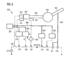
- FIG 3 shows a conventional system for triggering an emergency system of a wind turbine.
- the system 300 comprises a blade 306, which is mounted on a hub 305.
- the hub is coupled to a main shaft 304 which is coupled to a gear box 303.
- Attached to the main shaft 304 is a sensor 382 for sensing a low speed (LS).
- Attached to the gear box 303 is a sensor 372 for sensing a high speed (HS).
- LS low speed
- HS high speed
- An overspeed is measured by a slave module (IOM1) 370 receiving a signal from the HS sensor 372 and is detected by the Main Computer (MC) 301.
- the limit for the overspeed is a parameter, which is stored in the main controller.
- the HS sensor 372 is an inductive sensor.
- the slave modules 360, 370, 309, 350 in the hub are able to break the safety circuit for example via switches 361, 331, 351, but this feature is today only used if a communication error at the CAN BUS 308 is detected, or if they are restarted by the watch-dog internal in the slave modules.
- a low speed (LS) monitoring unit (LMU) 380 monitors the LS speed, and trigs the hydraulic emergency system by a hard wired emergency circuit 361, 381 if the limits are exceeded.
- the LMU outputs a speed feedback to the main computer, which are supervised to insure that the LMU is in operation.
- a high speed (HS) centrifugal unit (HCU) 302 trigs the hard wired emergency circuit 307 if the limit is exceeded.
- a speed sensor error is detected by to large differences between the generator HS speed and the generator LS speed.
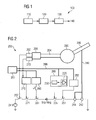
- FIG 2 illustrates a system according to a further embodiment of the invention.
- the system 200 comprises a blade 206, which is mounted on a hub 205.
- the hub is coupled to a main shaft 204 which is coupled to a gear box 203.
- Attached to the gear box 203 is a sensor 272 for sensing a high speed (HS).
- HS high speed
- An overspeed is measured by a slave module (IOM1) 270 receiving a signal from the HS sensor 272 and is detected by the Main Computer (MC) 201.
- the limit for the overspeed is a parameter, which is stored in the main controller.
- the HS sensor 272 is an inductive sensor.
- a controller over speed, as it is called, trigs the hydraulic emergency system 240, comprising at least two hydraulic valves 241, 242, by activating the "Safety Switch" 271.
- the slave modules 260, 270, 209, 250 in the hub are able to break the safety circuit for example via switches 261, 231, 251, but this feature is only used if a communication error at the CAN BUS 208 is detected, or if they are restarted by the watch-dog internal in the slave modules.
- the system 200 comprises a smart LMU unit or estimation unit 230, which is based on the speed estimation 220 which is a sub result in rotor azimuth estimation.
- the sensor is an accelerometer, sensing the direction of the gravity forces. The speed measurement is very precise in mean, seen over one revolution. In normal operation, the speed measurement will be sufficient for monitoring application (about 2% accuracy).
- This estimator is placed in the hub module 209, which is separated from the main computer 201.
- the hub module has also individual access to the emergency circuit via switch 231, so that it can stop the turbine itself.
- a high speed (HS) centrifugal unit (HCU) 202 trigs the hard wired emergency circuit 207 if the limit is exceeded.
- a speed sensor error is detected by to large differences between the generator HS speed and the generator LS speed, wherein the value of the HS-speed sensor is compared with the rotor-speed estimated by the estimation unit. This gives the possibility to remove the LS-speed sensor as used in the conventional system. It might be necessary to run a calibration on the speed estimator (estimation unit) the first 30 min after the erection before the turbine can be released for operation.
- the speed is estimated using two axis accelerometer in the hub. This makes it possible to remove a speed sensor and replace the LS speed unit (LMU) for example with a software function in the existing hub-controller. Speed sensor error can also be detected by comparing the generator speed sensor with the estimated speed.
- LMU LS speed unit
Abstract
Description
- The present invention relates to the technical field of triggering emergency systems of power generating machines such as wind turbines. In particular, the present invention relates to a system and to a method for triggering an emergency system of a wind turbine. Further, the present invention relates to a wind turbine, to a computer program and to a computer-readable medium, which are adapted for carrying out the above mentioned triggering method.
- When rotors of wind turbines are mounted on a hub, they have an emergency system for switching off the rotor or the wind turbine if there is an overspeed or a too large difference between generator high speed and generator low speed.
- Conventional systems of a wind turbine have a redundant over speed detection system, which is able to trig an emergency safety system. An overspeed controller comprises a slave module for measuring the overspeed and a Main Computer (MC) for detecting the overspeed. The limit is a parameter in the main controller, and the sensor is an inductive sensor. A controller over speed, as it is called, trigs the hydraulic emergency system by activating a "Safety Switch". The slave modules in the hub are able to break the safety circuit, but this feature is only used if a communication error at a CAN BUS in the system is detected, or if they are restarted by a watch-dog internal in the slave modules.
- Conventional systems comprises further a Low speed Monitoring Unit (LMU) for monitoring the LS (low speed)-speed, and triggering the hydraulic emergency system by hard wired emergency circuit if the limits are exceeded. The LMU outputs a speed feedback to the main computer, which is supervised to insure that the LMU is in operation. Conventional systems comprise furthermore A High Speed (HS) Centrifugal Unit (HCU) for triggering the hard wired emergency circuit if the limit is exceeded. Further, a Speed Sensor Error may be detected by to large differences between generator HS speed and generator LS speed.
- There may be a need for providing a system providing a cost effective approach for triggering an emergency system of a wind turbine.
- This need may be met by the subject matter according to the independent claims. Advantageous embodiments of the present invention are described by the dependent claims.
- According to a first aspect of the invention there is provided a system for triggering an emergency system of a wind turbine. The system comprises a sensor for sensing an acceleration value of a portion of the rotor of the wind turbine, an estimation unit coupled to the sensor, wherein the estimation unit is adapted for receiving the acceleration value from the sensor and for estimating a rotor rotational speed value of the rotor of the wind turbine based on the acceleration value, and a triggering unit coupled to the estimation unit, wherein the triggering unit is adapted for receiving the rotor rotational speed value and for triggering the emergency system, if the rotor rotational speed value exceeds a predefined limit value.
- The described system is based on the idea that during for example a rotor azimuth estimation, sub results may be used for a measurement of the acceleration of a portion of the rotor. The measured or sensed acceleration value of a portion of the rotor may be used for estimating a rotational speed of the rotor. The speed measurement may be very precise in mean, seen over one revolution. In normal operation, the speed measurement may be sufficient for monitoring application (about 2% accuracy). The system may allow to remove the LMU as used in conventional systems and also to remove the low speed sensor.
- According to an embodiment of the invention, the sensor is an accelerometer. The accelerometer may be located in the hub or at a portion of the rotor, for example the blades. In conventional systems, a normal speed sensor was located on the main shaft. In this embodiment, for example two axis accelerometers may be used.
- According to a further embodiment of the invention, the sensor is adapted for sensing the direction of the gravity forces of the rotor. The gravity forces may occur during movement of the rotor.
- According to a further embodiment of the invention, the estimation unit is located in a control unit of the wind turbine. The control unit may be for example the main controller. The estimation unit may also be located in a hub module, which is separated from the main controller. The Hub module may have individual access to the emergency circuit, so that it may stop the turbine itself.
- According to a further embodiment of the invention, the system comprises further a high rotational speed sensor for sensing a high rotational speed value of the rotor, a comparator unit adapted for receiving the high rotational speed value from the high rotational speed sensor and for receiving the rotor rotational speed value, wherein the comparator unit is further adapted for obtaining a comparison value based on a comparison of the high rotational speed value and the rotor rotational speed value, and a detection unit adapted for detecting a speed sensor error based on the result of the comparator unit, if the comparison value exceeds a predefined limit. By this embodiment, it may be possible to remove the LS speed sensor also for measuring a speed sensor error. In conventional systems, the speed sensor error is measured by detecting to large differences between generator HS speed and generator LS speed. Both speeds are measured in conventional systems by speed sensors, attached to the gearbox and the main shaft.
- According to a further embodiment of the invention, the system comprises further an over speed controller for triggering the emergency system, if the detected over speed exceeds a predefined limit value. An over speed may be measured by a slave module and detected by the Main Computer (MC). The limit value may be a parameter stored in the main controller. A controller over speed, as it may be called, may trigger the hydraulic emergency system by activating the "Safety Switch". The safety switch is a switch, which may close a circuit for activating or triggering the emergency system. The slave modules in the hub may be able to break the safety circuit, but this feature may be used for example only if a communication error at the CAN BUS is detected, or if they are restarted by the watch-dog internal in the slave modules.
- According to a further embodiment of the invention, the over speed controller comprises an inductive sensor for sensing the over speed. The inductive sensor may be an electronic proximity sensor. The sensor may be also used for sensing the HS speed.
- According to a further aspect of the invention there is provided a method for triggering an emergency system of a wind turbine. The method comprises sensing an acceleration value of a portion of a rotor of the wind turbine by a sensor, receiving the acceleration value from the sensor by an estimation unit coupled to the sensor, estimating a rotor rotational speed value of the rotor of the wind turbine based on the acceleration value, receiving the rotor rotational speed value from the estimation unit by a triggering unit coupled to the estimation unit, and triggering the emergency system, if the rotor rotational speed value exceeds a predefined limit value.
- Also the described method is based on the idea that, during for example a rotor azimuth estimation, sub results of the rotor azimuth estimation may be used for a measurement of the acceleration of a portion of the rotor so that a low speed (LS) sensor is not necessary.
- According to a further aspect of the invention there is provided a wind turbine, which comprises an emergency system and a system for triggering the emergency system of the wind turbine as described above.
- The wind turbine may comprise the system for example within a controller or computer. Thus, values of a rotor azimuth estimation may be reused for triggering an emergency system.
- According to a further aspect of the invention there is provided a computer program for triggering an emergency system of a wind turbine. The computer program, when being executed by a data processor, is adapted for controlling the above described method for triggering an emergency system of a wind turbine.
- As used herein, reference to a computer program is intended to be equivalent to a reference to a program element containing instructions for controlling a computer system to coordinate the performance of the above described method.
- The computer program may be implemented as computer readable instruction code in any suitable programming language, such as, for example, JAVA, C++, and may be stored on a computer-readable medium (removable disk, volatile or non-volatile memory, embedded memory/processor, etc.). The instruction code is operable to program a computer or any other programmable device to carry out the intended functions. The computer program may be available from a network, such as the World Wide Web, from which it may be downloaded.
- The invention may be realized by means of a computer program respectively software. However, the invention may also be realized by means of one or more specific electronic circuits respectively hardware. Furthermore, the invention may also be realized in a hybrid form, i.e. in a combination of software modules and hardware modules.
- According to a further aspect of the invention there is provided a computer-readable medium (for instance a CD, a DVD, a USB stick, a floppy disk or a hard disk), in which a computer program for triggering an emergency system of a wind turbine is stored, which computer program, when being executed by a processor, is adapted to carry out or control a method for triggering an emergency system of a wind turbine.
- It has to be noted that embodiments of the invention have been described with reference to different subject matters. In particular, some embodiments have been described with reference to method type claims whereas other embodiments have been described with reference to apparatus type claims. However, a person skilled in the art will gather from the above and the following description that, unless other notified, in addition to any combination of features belonging to one type of subject matter also any combination between features relating to different subject matters, in particular between features of the method type claims and features of the apparatus type claims is considered as to be disclosed with this document.
- The aspects defined above and further aspects of the present invention are apparent from the examples of embodiment to be described hereinafter and are explained with reference to the examples of embodiment. The invention will be described in more detail hereinafter with reference to examples of embodiment but to which the invention is not limited.
-
-
Figure 1 shows a system according to an embodiment of the present invention. -
Figure 2 shows a system according to a further embodiment of the present invention. -
Figure 3 shows a conventional system for triggering an emergency system of a wind turbine. - The illustration in the drawing is schematically. It is noted that in different figures, similar or identical elements are provided with the same reference signs or with reference signs, which are different from the corresponding reference signs only within the first digit.
-
Figure 1 shows an exemplary embodiment according to the invention. Thesystem 100 for triggering an emergency system of a wind turbine comprises asensor 110 for sensing an acceleration value of a portion of the rotor of the wind turbine. Anestimation unit 120 is coupled to thesensor 110. The estimation unit is adapted for receiving the acceleration value from the sensor and for estimating a rotor rotational speed value of the rotor of the wind turbine based on the acceleration value. A triggeringunit 130 is coupled to theestimation unit 120. The triggering unit is adapted for receiving the rotor rotational speed value and for triggering theemergency system 140, if the rotor rotational speed value exceeds a predefined limit value. The predefined limit value may be stored in a hub module of the wind turbine system. -
Figure 3 shows a conventional system for triggering an emergency system of a wind turbine. Thesystem 300 comprises ablade 306, which is mounted on ahub 305. The hub is coupled to amain shaft 304 which is coupled to agear box 303. Attached to themain shaft 304 is asensor 382 for sensing a low speed (LS). Attached to thegear box 303 is asensor 372 for sensing a high speed (HS). - An overspeed is measured by a slave module (IOM1) 370 receiving a signal from the
HS sensor 372 and is detected by the Main Computer (MC) 301. The limit for the overspeed is a parameter, which is stored in the main controller. TheHS sensor 372 is an inductive sensor. A controller over speed, as it is called, trigs thehydraulic emergency system 340, comprising at least twohydraulic valves - The
slave modules switches CAN BUS 308 is detected, or if they are restarted by the watch-dog internal in the slave modules. - A low speed (LS) monitoring unit (LMU) 380 monitors the LS speed, and trigs the hydraulic emergency system by a hard wired
emergency circuit emergency circuit 307 if the limit is exceeded. A speed sensor error is detected by to large differences between the generator HS speed and the generator LS speed. -
Figure 2 illustrates a system according to a further embodiment of the invention. As the conventional system illustrated inFigure 3 , thesystem 200 comprises ablade 206, which is mounted on ahub 205. The hub is coupled to amain shaft 204 which is coupled to agear box 203. Attached to thegear box 203 is asensor 272 for sensing a high speed (HS). - An overspeed is measured by a slave module (IOM1) 270 receiving a signal from the
HS sensor 272 and is detected by the Main Computer (MC) 201. The limit for the overspeed is a parameter, which is stored in the main controller. TheHS sensor 272 is an inductive sensor. A controller over speed, as it is called, trigs thehydraulic emergency system 240, comprising at least twohydraulic valves - The
slave modules switches CAN BUS 208 is detected, or if they are restarted by the watch-dog internal in the slave modules. - In contrast to the conventional system, where a low speed (LS) monitoring unit (LMU) 380 monitors the LS speed, and trigs the hydraulic emergency system by a hard wired
emergency circuit system 200 according to this embodiment comprises a smart LMU unit orestimation unit 230, which is based on thespeed estimation 220 which is a sub result in rotor azimuth estimation. The sensor is an accelerometer, sensing the direction of the gravity forces. The speed measurement is very precise in mean, seen over one revolution. In normal operation, the speed measurement will be sufficient for monitoring application (about 2% accuracy). This estimator is placed in thehub module 209, which is separated from themain computer 201. The hub module has also individual access to the emergency circuit viaswitch 231, so that it can stop the turbine itself. - A high speed (HS) centrifugal unit (HCU) 202 trigs the hard wired
emergency circuit 207 if the limit is exceeded. A speed sensor error is detected by to large differences between the generator HS speed and the generator LS speed, wherein the value of the HS-speed sensor is compared with the rotor-speed estimated by the estimation unit. This gives the possibility to remove the LS-speed sensor as used in the conventional system. It might be necessary to run a calibration on the speed estimator (estimation unit) the first 30 min after the erection before the turbine can be released for operation. - Instead of using a normal speed sensor on the main shaft as in the conventional system, the speed is estimated using two axis accelerometer in the hub. This makes it possible to remove a speed sensor and replace the LS speed unit (LMU) for example with a software function in the existing hub-controller. Speed sensor error can also be detected by comparing the generator speed sensor with the estimated speed.
- It should be noted that the term "comprising" does not exclude other elements or steps and "a" or "an" does not exclude a plurality. Also elements described in association with different embodiments may be combined. It should also be noted that reference signs in the claims should not be construed as limiting the scope of the claims.
Claims (11)
- System for triggering an emergency system of a wind turbine, the system comprising
a sensor for sensing an acceleration value of a portion of the rotor of the wind turbine,
an estimation unit coupled to the sensor, wherein the estimation unit is adapted for receiving the acceleration value from the sensor and for estimating a rotor rotational speed value of the rotor of the wind turbine based on the acceleration value, and
a triggering unit coupled to the estimation unit, wherein the triggering unit is adapted for receiving the rotor rotational speed value and for triggering the emergency system, if the rotor rotational speed value exceeds a predefined limit value. - System as set forth in claim 1, wherein
the sensor is an accelerometer. - System as set forth in one of the preceding claims, wherein
the sensor is adapted for sensing the direction of the gravity forces of the rotor. - System as set forth in one of the preceding claims, wherein
the estimation unit is located in a control unit of the wind turbine. - System as set forth in one of the preceding claims, further comprising
a high rotational speed sensor for sensing a high rotational speed value of the rotor,
a comparator unit adapted for receiving the high rotational speed value from the high rotational speed sensor and for receiving the rotor rotational speed value, wherein the comparator unit is further adapted for obtaining a comparison value based on a comparison of the high rotational speed value and the rotor rotational speed value, and
a detection unit adapted for detecting a speed sensor error based on the result of the comparator unit, if the comparison value exceeds a predefined limit. - System as set forth in one of the preceding claims, further comprising
an over speed controller for triggering the emergency system, if the detected over speed exceeds a predefined limit value. - System as set forth in claim 6, wherein
the overspeed controller comprises an inductive sensor for sensing the over speed. - A wind turbine comprising
an emergency system and
a system for triggering the emergency system as set forth in one of the preceding claims. - Method for triggering an emergency system of a wind turbine, the method comprising
sensing an acceleration value of a portion of a rotor of the wind turbine by a sensor,
receiving the acceleration value from the sensor by an estimation unit coupled to the sensor,
estimating a rotor rotational speed value of the rotor of the wind turbine based on the acceleration value,
receiving the rotor rotational speed value from the estimation unit by a triggering unit coupled to the estimation unit, and
triggering the emergency system, if the rotor rotational speed value exceeds a predefined limit value. - A computer program for triggering an emergency system of a wind turbine, the computer program, when being executed by a data processor, is adapted for controlling the method as set forth claim 9.
- A computer-readable medium, in which a computer program for triggering an emergency system of a wind turbine is stored, which computer program, when being executed by a processor, is adapted to carry out or control a method as set forth in claim 9.
Priority Applications (6)
| Application Number | Priority Date | Filing Date | Title |
|---|---|---|---|
| EP09015864A EP2339174A1 (en) | 2009-12-22 | 2009-12-22 | System for triggering an emergency system of wind turbine |
| NZ590012A NZ590012A (en) | 2009-12-22 | 2010-12-16 | A system for triggering an emergency system of a wind turbine to stop the wind turbine |
| US12/969,927 US8600570B2 (en) | 2009-12-22 | 2010-12-16 | System for triggering an emergency system of a wind turbine |
| CA2725964A CA2725964A1 (en) | 2009-12-22 | 2010-12-20 | System for triggering an emergency system of a wind turbine |
| CN2010105998618A CN102102624A (en) | 2009-12-22 | 2010-12-22 | System for triggering an emergency system of wind turbine |
| JP2010286070A JP2011132961A (en) | 2009-12-22 | 2010-12-22 | System and method for triggering emergency system of wind turbine, wind turbine, computer program and computer readable record medium |
Applications Claiming Priority (1)
| Application Number | Priority Date | Filing Date | Title |
|---|---|---|---|
| EP09015864A EP2339174A1 (en) | 2009-12-22 | 2009-12-22 | System for triggering an emergency system of wind turbine |
Publications (1)
| Publication Number | Publication Date |
|---|---|
| EP2339174A1 true EP2339174A1 (en) | 2011-06-29 |
Family
ID=42260319
Family Applications (1)
| Application Number | Title | Priority Date | Filing Date |
|---|---|---|---|
| EP09015864A Withdrawn EP2339174A1 (en) | 2009-12-22 | 2009-12-22 | System for triggering an emergency system of wind turbine |
Country Status (6)
| Country | Link |
|---|---|
| US (1) | US8600570B2 (en) |
| EP (1) | EP2339174A1 (en) |
| JP (1) | JP2011132961A (en) |
| CN (1) | CN102102624A (en) |
| CA (1) | CA2725964A1 (en) |
| NZ (1) | NZ590012A (en) |
Cited By (1)
| Publication number | Priority date | Publication date | Assignee | Title |
|---|---|---|---|---|
| EP3128170A1 (en) | 2015-08-06 | 2017-02-08 | Nordex Energy GmbH | Wind power facility with a yaw drive |
Families Citing this family (5)
| Publication number | Priority date | Publication date | Assignee | Title |
|---|---|---|---|---|
| DK2365215T3 (en) * | 2010-03-10 | 2013-01-28 | Siemens Ag | Controlling the rotational speed of a wind turbine based on rotor acceleration |
| US20130259686A1 (en) * | 2012-03-30 | 2013-10-03 | General Electric Company | System and method for controlling a wind turbine |
| KR101466080B1 (en) | 2013-05-03 | 2014-11-27 | 삼성중공업 주식회사 | Apparatus and method of controlling wind turbine |
| JP6570907B2 (en) * | 2014-11-06 | 2019-09-04 | 株式会社東芝 | Airflow generator and wind power generation system |
| CN111502913B (en) * | 2019-01-30 | 2022-04-19 | 北京金风科创风电设备有限公司 | Wind generating set, variable pitch control method and device |
Citations (7)
| Publication number | Priority date | Publication date | Assignee | Title |
|---|---|---|---|---|
| DE19534404A1 (en) * | 1995-09-16 | 1997-03-20 | En Umwelt Beratung E V I | Wind power installation technical state monitoring method |
| US6265785B1 (en) * | 1998-11-30 | 2001-07-24 | Zond Systems, Inc. | Non-volatile over speed control system for wind turbines |
| US20040207208A1 (en) * | 1997-08-08 | 2004-10-21 | Mikhail Amir S | Variable speed wind turbine generator |
| US20070018457A1 (en) * | 2005-07-22 | 2007-01-25 | Gamesa Eolica, S.A. | Method of operating a wind turbine |
| DE102006001613A1 (en) * | 2006-01-11 | 2007-07-12 | Repower Systems Ag | Method for operating a wind turbine and wind turbine |
| EP1903213A2 (en) * | 2006-09-20 | 2008-03-26 | Hitachi, Ltd. | Wind turbine and wind turbine rotor pitch control method |
| EP2211055A1 (en) * | 2009-01-22 | 2010-07-28 | Vestas Wind Systems A/S | Control of rotor during a stop process of a wind turbine |
Family Cites Families (10)
| Publication number | Priority date | Publication date | Assignee | Title |
|---|---|---|---|---|
| US4348155A (en) * | 1980-03-17 | 1982-09-07 | United Technologies Corporation | Wind turbine blade pitch control system |
| US7157901B1 (en) * | 2000-02-08 | 2007-01-02 | Robert Bosch Gmbh | Inductive sensor (speed sensor) with a conical coil base body |
| JP4494813B2 (en) * | 2004-02-03 | 2010-06-30 | 富士重工業株式会社 | Horizontal axis wind turbine and control method thereof |
| JP4730704B2 (en) * | 2005-05-31 | 2011-07-20 | 東京電力株式会社 | Blade structure |
| JP4774843B2 (en) * | 2005-07-13 | 2011-09-14 | シンフォニアテクノロジー株式会社 | Wind power generation equipment |
| JP4738206B2 (en) * | 2006-02-28 | 2011-08-03 | 三菱重工業株式会社 | Wind power generation system and control method thereof |
| JP4885570B2 (en) * | 2006-03-03 | 2012-02-29 | ナブテスコ株式会社 | Windmill sensor mechanism and windmill vibration reduction method |
| JP4885096B2 (en) * | 2007-09-11 | 2012-02-29 | 三菱重工業株式会社 | Wind power generation system and control method thereof |
| DE102008012957A1 (en) * | 2008-03-06 | 2009-09-10 | Repower Systems Ag | Method for operating a wind turbine and wind turbine |
| US8128361B2 (en) * | 2008-12-19 | 2012-03-06 | Frontier Wind, Llc | Control modes for extendable rotor blades |
-
2009
- 2009-12-22 EP EP09015864A patent/EP2339174A1/en not_active Withdrawn
-
2010
- 2010-12-16 NZ NZ590012A patent/NZ590012A/en not_active IP Right Cessation
- 2010-12-16 US US12/969,927 patent/US8600570B2/en not_active Expired - Fee Related
- 2010-12-20 CA CA2725964A patent/CA2725964A1/en not_active Abandoned
- 2010-12-22 JP JP2010286070A patent/JP2011132961A/en active Pending
- 2010-12-22 CN CN2010105998618A patent/CN102102624A/en active Pending
Patent Citations (7)
| Publication number | Priority date | Publication date | Assignee | Title |
|---|---|---|---|---|
| DE19534404A1 (en) * | 1995-09-16 | 1997-03-20 | En Umwelt Beratung E V I | Wind power installation technical state monitoring method |
| US20040207208A1 (en) * | 1997-08-08 | 2004-10-21 | Mikhail Amir S | Variable speed wind turbine generator |
| US6265785B1 (en) * | 1998-11-30 | 2001-07-24 | Zond Systems, Inc. | Non-volatile over speed control system for wind turbines |
| US20070018457A1 (en) * | 2005-07-22 | 2007-01-25 | Gamesa Eolica, S.A. | Method of operating a wind turbine |
| DE102006001613A1 (en) * | 2006-01-11 | 2007-07-12 | Repower Systems Ag | Method for operating a wind turbine and wind turbine |
| EP1903213A2 (en) * | 2006-09-20 | 2008-03-26 | Hitachi, Ltd. | Wind turbine and wind turbine rotor pitch control method |
| EP2211055A1 (en) * | 2009-01-22 | 2010-07-28 | Vestas Wind Systems A/S | Control of rotor during a stop process of a wind turbine |
Cited By (1)
| Publication number | Priority date | Publication date | Assignee | Title |
|---|---|---|---|---|
| EP3128170A1 (en) | 2015-08-06 | 2017-02-08 | Nordex Energy GmbH | Wind power facility with a yaw drive |
Also Published As
| Publication number | Publication date |
|---|---|
| CN102102624A (en) | 2011-06-22 |
| JP2011132961A (en) | 2011-07-07 |
| US8600570B2 (en) | 2013-12-03 |
| NZ590012A (en) | 2012-07-27 |
| CA2725964A1 (en) | 2011-06-22 |
| US20110153097A1 (en) | 2011-06-23 |
Similar Documents
| Publication | Publication Date | Title |
|---|---|---|
| EP2365215B1 (en) | Rotational speed control of a wind turbine based on rotor acceleration | |
| US8600570B2 (en) | System for triggering an emergency system of a wind turbine | |
| EP2886856B1 (en) | Detecting a pitch angle adjustment fault | |
| CA2844165C (en) | System and method for reducing loads acting on a wind turbine in response to transient wind conditions | |
| EP2952860B1 (en) | System and method for protecting rotary machines | |
| EP2644888A2 (en) | Control system and method for avoiding overspeed of a wind turbine | |
| EP2678556B1 (en) | A safety system for a wind turbine | |
| EP2463517A1 (en) | Method and control system for reducing vibrations of a wind turbine | |
| EP2690286A1 (en) | Monitoring arrangement | |
| CN104863794A (en) | Yaw Control System And Yaw Control Method For Wind Turbine Generator | |
| EP3502463B1 (en) | System and method for protecting wind turbines during wind gusts | |
| CN110352300B (en) | Method for monitoring the performance of a wind turbine system and wind turbine system | |
| CN110700997A (en) | Method for monitoring rotating speed of impeller of wind power pitch control system | |
| WO2012136277A1 (en) | Proactive control of the operation of a wind turbine | |
| EP2881549B1 (en) | System and method for preventing an emergency over-speed condition in a rotating machine | |
| CN111075646A (en) | Overspeed safety control device for wind driven generator | |
| EP3722597B1 (en) | System and method for preventing catastrophic damage in drivetrain of a wind turbine | |
| EP3844388B1 (en) | Trip reduction tool for a wind turbine power system | |
| WO2022196517A1 (en) | Control device for power generation system | |
| CN117529666A (en) | Determining wind turbine rotor speed | |
| CN117836514A (en) | Identifying recurring free-flowing wind disturbances associated with a wind turbine | |
| KR101368754B1 (en) | Output controlling method and device of wind power generating system using angle of attack | |
| KR20200029931A (en) | Fault diagnosis method of wind generator | |
| BR102014005474B1 (en) | SYSTEM AND METHOD FOR REDUCING THE LOADS ACTING ON A WIND TURBINE |
Legal Events
| Date | Code | Title | Description |
|---|---|---|---|
| PUAI | Public reference made under article 153(3) epc to a published international application that has entered the european phase |
Free format text: ORIGINAL CODE: 0009012 |
|
| AK | Designated contracting states |
Kind code of ref document: A1 Designated state(s): AT BE BG CH CY CZ DE DK EE ES FI FR GB GR HR HU IE IS IT LI LT LU LV MC MK MT NL NO PL PT RO SE SI SK SM TR |
|
| AX | Request for extension of the european patent |
Extension state: AL BA RS |
|
| 17P | Request for examination filed |
Effective date: 20110808 |
|
| RAP1 | Party data changed (applicant data changed or rights of an application transferred) |
Owner name: SIEMENS AKTIENGESELLSCHAFT |
|
| GRAP | Despatch of communication of intention to grant a patent |
Free format text: ORIGINAL CODE: EPIDOSNIGR1 |
|
| INTG | Intention to grant announced |
Effective date: 20151106 |
|
| STAA | Information on the status of an ep patent application or granted ep patent |
Free format text: STATUS: THE APPLICATION IS DEEMED TO BE WITHDRAWN |
|
| 18D | Application deemed to be withdrawn |
Effective date: 20160317 |