EP2333325A1 - Brake system, generator and wind turbine - Google Patents
Brake system, generator and wind turbine Download PDFInfo
- Publication number
- EP2333325A1 EP2333325A1 EP09014766A EP09014766A EP2333325A1 EP 2333325 A1 EP2333325 A1 EP 2333325A1 EP 09014766 A EP09014766 A EP 09014766A EP 09014766 A EP09014766 A EP 09014766A EP 2333325 A1 EP2333325 A1 EP 2333325A1
- Authority
- EP
- European Patent Office
- Prior art keywords
- brake
- generator
- rotor
- brake system
- stator
- Prior art date
- Legal status (The legal status is an assumption and is not a legal conclusion. Google has not performed a legal analysis and makes no representation as to the accuracy of the status listed.)
- Granted
Links
- 238000005452 bending Methods 0.000 claims description 5
- 238000003475 lamination Methods 0.000 description 6
- 238000004804 winding Methods 0.000 description 5
- 238000012423 maintenance Methods 0.000 description 3
- 238000010276 construction Methods 0.000 description 1
- 238000011161 development Methods 0.000 description 1
- 230000018109 developmental process Effects 0.000 description 1
- 230000001360 synchronised effect Effects 0.000 description 1
Images

Classifications
-
- H—ELECTRICITY
- H02—GENERATION; CONVERSION OR DISTRIBUTION OF ELECTRIC POWER
- H02K—DYNAMO-ELECTRIC MACHINES
- H02K7/00—Arrangements for handling mechanical energy structurally associated with dynamo-electric machines, e.g. structural association with mechanical driving motors or auxiliary dynamo-electric machines
- H02K7/18—Structural association of electric generators with mechanical driving motors, e.g. with turbines
- H02K7/1807—Rotary generators
- H02K7/1823—Rotary generators structurally associated with turbines or similar engines
- H02K7/183—Rotary generators structurally associated with turbines or similar engines wherein the turbine is a wind turbine
- H02K7/1838—Generators mounted in a nacelle or similar structure of a horizontal axis wind turbine
-
- F—MECHANICAL ENGINEERING; LIGHTING; HEATING; WEAPONS; BLASTING
- F03—MACHINES OR ENGINES FOR LIQUIDS; WIND, SPRING, OR WEIGHT MOTORS; PRODUCING MECHANICAL POWER OR A REACTIVE PROPULSIVE THRUST, NOT OTHERWISE PROVIDED FOR
- F03D—WIND MOTORS
- F03D7/00—Controlling wind motors
- F03D7/02—Controlling wind motors the wind motors having rotation axis substantially parallel to the air flow entering the rotor
- F03D7/0244—Controlling wind motors the wind motors having rotation axis substantially parallel to the air flow entering the rotor for braking
- F03D7/0248—Controlling wind motors the wind motors having rotation axis substantially parallel to the air flow entering the rotor for braking by mechanical means acting on the power train
-
- F—MECHANICAL ENGINEERING; LIGHTING; HEATING; WEAPONS; BLASTING
- F03—MACHINES OR ENGINES FOR LIQUIDS; WIND, SPRING, OR WEIGHT MOTORS; PRODUCING MECHANICAL POWER OR A REACTIVE PROPULSIVE THRUST, NOT OTHERWISE PROVIDED FOR
- F03D—WIND MOTORS
- F03D80/00—Details, components or accessories not provided for in groups F03D1/00 - F03D17/00
- F03D80/80—Arrangement of components within nacelles or towers
- F03D80/88—Arrangement of components within nacelles or towers of mechanical components
-
- F—MECHANICAL ENGINEERING; LIGHTING; HEATING; WEAPONS; BLASTING
- F03—MACHINES OR ENGINES FOR LIQUIDS; WIND, SPRING, OR WEIGHT MOTORS; PRODUCING MECHANICAL POWER OR A REACTIVE PROPULSIVE THRUST, NOT OTHERWISE PROVIDED FOR
- F03D—WIND MOTORS
- F03D9/00—Adaptations of wind motors for special use; Combinations of wind motors with apparatus driven thereby; Wind motors specially adapted for installation in particular locations
- F03D9/20—Wind motors characterised by the driven apparatus
- F03D9/25—Wind motors characterised by the driven apparatus the apparatus being an electrical generator
-
- H—ELECTRICITY
- H02—GENERATION; CONVERSION OR DISTRIBUTION OF ELECTRIC POWER
- H02K—DYNAMO-ELECTRIC MACHINES
- H02K7/00—Arrangements for handling mechanical energy structurally associated with dynamo-electric machines, e.g. structural association with mechanical driving motors or auxiliary dynamo-electric machines
- H02K7/10—Structural association with clutches, brakes, gears, pulleys or mechanical starters
- H02K7/102—Structural association with clutches, brakes, gears, pulleys or mechanical starters with friction brakes
-
- F—MECHANICAL ENGINEERING; LIGHTING; HEATING; WEAPONS; BLASTING
- F03—MACHINES OR ENGINES FOR LIQUIDS; WIND, SPRING, OR WEIGHT MOTORS; PRODUCING MECHANICAL POWER OR A REACTIVE PROPULSIVE THRUST, NOT OTHERWISE PROVIDED FOR
- F03D—WIND MOTORS
- F03D80/00—Details, components or accessories not provided for in groups F03D1/00 - F03D17/00
- F03D80/70—Bearing or lubricating arrangements
-
- F—MECHANICAL ENGINEERING; LIGHTING; HEATING; WEAPONS; BLASTING
- F05—INDEXING SCHEMES RELATING TO ENGINES OR PUMPS IN VARIOUS SUBCLASSES OF CLASSES F01-F04
- F05B—INDEXING SCHEME RELATING TO WIND, SPRING, WEIGHT, INERTIA OR LIKE MOTORS, TO MACHINES OR ENGINES FOR LIQUIDS COVERED BY SUBCLASSES F03B, F03D AND F03G
- F05B2260/00—Function
- F05B2260/30—Retaining components in desired mutual position
- F05B2260/31—Locking rotor in position
-
- F—MECHANICAL ENGINEERING; LIGHTING; HEATING; WEAPONS; BLASTING
- F05—INDEXING SCHEMES RELATING TO ENGINES OR PUMPS IN VARIOUS SUBCLASSES OF CLASSES F01-F04
- F05B—INDEXING SCHEME RELATING TO WIND, SPRING, WEIGHT, INERTIA OR LIKE MOTORS, TO MACHINES OR ENGINES FOR LIQUIDS COVERED BY SUBCLASSES F03B, F03D AND F03G
- F05B2260/00—Function
- F05B2260/90—Braking
- F05B2260/902—Braking using frictional mechanical forces
-
- H—ELECTRICITY
- H02—GENERATION; CONVERSION OR DISTRIBUTION OF ELECTRIC POWER
- H02K—DYNAMO-ELECTRIC MACHINES
- H02K2213/00—Specific aspects, not otherwise provided for and not covered by codes H02K2201/00 - H02K2211/00
- H02K2213/12—Machines characterised by the modularity of some components
-
- Y—GENERAL TAGGING OF NEW TECHNOLOGICAL DEVELOPMENTS; GENERAL TAGGING OF CROSS-SECTIONAL TECHNOLOGIES SPANNING OVER SEVERAL SECTIONS OF THE IPC; TECHNICAL SUBJECTS COVERED BY FORMER USPC CROSS-REFERENCE ART COLLECTIONS [XRACs] AND DIGESTS
- Y02—TECHNOLOGIES OR APPLICATIONS FOR MITIGATION OR ADAPTATION AGAINST CLIMATE CHANGE
- Y02E—REDUCTION OF GREENHOUSE GAS [GHG] EMISSIONS, RELATED TO ENERGY GENERATION, TRANSMISSION OR DISTRIBUTION
- Y02E10/00—Energy generation through renewable energy sources
- Y02E10/70—Wind energy
- Y02E10/72—Wind turbines with rotation axis in wind direction
Definitions
- the invention relates to a brake system, especially for a generator, a generator, especially a direct drive generator, and a wind turbine.
- the first type of a wind turbine is the more classical type of a wind turbine comprising a gearbox arranged between a main shaft and a generator of the wind turbine.
- the second type of a wind turbine is a gearless type, where the gearbox and the conventional generator are substituted by a multipolar generator, a so called direct drive or directly driven generator.
- Such a direct drive generator can be made as a synchronous generator with winded rotor or with permanent magnets attached to the rotor, or it can be designed as an alternative type of a generator.
- One of the challenges with the direct drive generator is the mechanical brake system.
- the brake system needs to be located at the slowing rotating axis as no gear box is used.
- the brake system needs to withstand a large braking moment and large brake discs and callipers are necessary.
- the US 2005/230979 describes a wind turbine which minimizes the size of the nacelle while providing adequate accessibility to components during maintenance operations.
- the wind turbine comprises: a nacelle and a blade rotor hub adjacent to said nacelle and a main shaft coupled to said hub and said nacelle.
- the generator is coupled to said shaft between said nacelle and said hub, wherein said generator includes generator rotor adjacent to said shaft, a stator positioned adjacent to and radially outward from said generator rotor; and a brake coupled to said generator and said shaft where the brake is positioned radially inward from said stator.
- the invention describes a solution that minimizes the brake system as the system can be more or less integrated into the generator.
- the proposed solution minimizes the size of the construction and also restricts the size of the brake system which is unwanted for a direct drive wind turbine where the size of the callipers and the brake disc should be as big as possible in order to withstand the high braking moments due to the slow rotational speed of the rotor.
- the brake system shown in US 2005/230979 also prevents passage though the generator and it is not possible to go into the hub from the nacelle/generator.
- the invention relates to a generator with an inner rotor configuration and it not possible to use the configuration for brake system with outer rotor configuration.
- a wind turbine comprising an electrical generator that includes a rotor assembly.
- the wind turbine includes a frictional braking system for slowing, stopping or keeping stopped the rotation of the wind rotor and rotor assembly.
- the wind turbine/generator set includes a generator that includes a stator assembly and a rotor assembly rotatable about a rotational axis.
- the rotor assembly includes an active portion and an active portion support supporting the active portion.
- the wind turbine/generator set further includes a wind rotor coupled to the rotor assembly, a generator support fixedly supporting the stator assembly and rotatable supporting the rotor assembly.
- the wind turbine/generator set includes at least braking device fixed relative to the generator support.
- the braking device includes at least one frictional member operatively configured for frictionally engaging at least a portion of the active portion support.
- the rotor assembly is generally located radially inward of the stator assembly.
- the first objective is solved by a brake system as claimed in claim 1.
- the second objective is solved by a generator as claimed in claim 13 and the third objective is solved by a wind turbine as claimed in claim 15.
- the depending claims define further developments of the invention.
- the inventive brake system comprises a rotor assembly, a stator assembly and a rotation axis.
- the rotor assembly comprises an outer portion which is located radially outward of the stator assembly.
- the outer portion comprises a brake disc.
- the stator assembly comprises at least one frictional member.
- the frictional member is operatively configured for frictionally engaging at least a portion of the brake disc.
- the inventive brake system may especially be used for a generator.
- the inventive brake system has the advantage, that the brake disc can be mounted on a cylindrical support structure of an outer rotor.
- the possible large diameter of the machine can be fully used in order to use a brake disc with largest possible diameter. This increases the efficiency of the brake.
- a bigger brake disc and bigger brake callipers can be used which provides a larger effective contact surface.
- a large effective contact surface is necessary in order to maintain the rotor in a parking position, for example.
- a further advantage is that more heat can be absorbed and distributed in a large brake disc compared with smaller brake discs.
- the inventive brake system can be part of a direct drive generator or it can be connected to a direct drive generator.
- the generator may have an outer rotor configuration.
- the brake disc extends radially inward from the outer portion of the rotor assembly to the rotation axis.
- the inventive brake system can be used for a direct drive generator.
- the inventive brake system may be part of a direct drive wind turbine with an outer rotor configuration.
- the rotor assembly may comprise a flange.
- the brake disc may be fastened to the flange.
- the flange may comprise a number of holes, preferably bolt holes. The holes may be radially spaced.
- the brake disc is fastened to the flange by bolts or screws.
- the brake system may be part of a wind turbine with a hub.
- the brake system especially the rotor assembly of the brake system, may comprise a near end which faces the hub and a far end which is located opposite to the hub.
- the flange, to which the brake disc is fastened may be located at the fast end of the rotor assembly, which means opposite of the hub.
- the inventive brake system may comprise a rotor support.
- the brake disc may be fastened to a flange of the rotor support, for example by bolts or screws.
- the stator assembly may comprise a stationary shaft.
- the at least one frictional member may be connected to the stationary shaft.
- the stator assembly may comprise a bed frame of a wind turbine.
- the at least one frictional member may be connected to the bed frame of the wind turbine.
- the stator assembly may comprise a stator support structure.
- the at least one frictional member may be connected to the stator support structure.
- the at least one frictional member for example at least one brake calliper, may be directly mounted to the stationary shaft or the bed frame of a wind turbine or a stator support structure.
- the at least one frictional member may extend radially outward regarding the rotation axis.
- the at least one frictional member may extend radially outward from the stator support structure or from the stationary shaft or from the bed frame of a wind turbine.
- the frictional member may comprise at least one brake calliper.
- the frictional member comprises at least one brake calliper on each side of the brake disc, preferably in order to enclose the brake disc.
- the at least one frictional member comprises at least one brake calliper system.
- the at least one calliper system may comprise at least to brake callipers located on each side of the brake disc opposite to each other.
- the brake calliper system may comprise at least one calliper bracket.
- the calliper bracket may be used for mounting the callipers and/or the brake calliper system to another component of the brake system, for example for mounting to the stationary shaft.
- Each brake calliper system may be connected to a calliper bracket.
- the brake calliper system may be designed such that it is aligned to the brake disc in axial direction in such a way that no bending moment, especially no axial bending moment, is experienced at a fixation point of the brake calliper system.
- the brake calliper system may be aligned to the brake disc in axial direction or it may be configured in such a way that no bending moment or substantially no bending moment is experienced at a fixation point of the brake calliper system to the calliper brackets.
- the inventive brake system may comprise a rotor lock system.
- the rotor lock system is integrated in the brake system.
- the rotor lock system comprises an automatic actuator.
- the rotor lock system may comprise an interlock, a snap-in lock, a block, an arrest or a barricade, preferably a number of the afore mentioned components.
- the rotor lock system can be realised such that the brake disc comprises a number of recesses, preferably in the inner surface of the brake disc, for example radially and/or symmetrically spaced.
- the stator assembly may comprise at least one piston, preferably a number of pistons.
- the piston/pistons is/are located such that it/they are prepared to engage with the recess/recesses.
- the pistons or the piston are/is prepared to engage with the corresponding recesses in the brake disc in order to lock the rotor in a parking position.
- the lock system may comprise an automatic actuator.
- the automatic actuator can advantageously be configured for pushing the pistons or the piston into the corresponding recesses.
- the actuator may comprise hydraulic or electrical means, for example a hydraulic cylinder.
- the pistons can be pushed into the corresponding recesses of the brake disc by hydraulic or electrical means. This way, it is possible to lock the rotor in an automated manner.
- the brake disc may comprise a number of radial segments. If the brake disc is divided into radial segments it is possible to exchange a large brake disc in an easy way.
- the inventive generator comprises an inventive brake system as previously described.
- the inventive generator has the same advantages as the inventive brake system.
- the generator may have an air gap, which is located between stator elements and rotor elements of the generator.
- the rotor elements contain permanent magnets for example, while the stator elements contain stacked laminate plates, which support at least one winding of the stator coil.
- the air gap should be relatively small to ensure a high efficiency of the generator.
- the air gap should stay in a range of only a few millimeters.
- direct drive generators show a diameter of several meters.
- Rotor elements and stator elements are typically arranged opposite to each other, thus the air gap has to ensure that they do not come into contact while the generator is at operation.
- the air gap should be very small to ensure the efficiency of the generator on the one hand while a certain width of the air gap is needed to prevent mechanical damages.
- the air gap of a generator can be determined by tolerances of the permanent magnets, which are part of the rotor, by tolerances of the stacked laminate-plates, which are part of the stator, and/or by tolerances of the coil-windings, which are part of the stator-coil. Also other elements of the generator contribute to the dimensions of the air gap.
- the air gap may be designed in a way that the elements of the rotor and of the stator do not get in contact, while the rotor rotates around its dedicated rotational axis.
- the inventive generator may comprise a rotor and a stator.
- the distance in radial direction (radial distance) between the brake disc and the frictional member is less than the distance in radial direction (radial distance) between the rotor and the stator.
- the frictional member can be the brake calliper or the brake calliper system or part of the brake calliper system, for instance a bracket.
- the radial distance between the brake disc and the frictional member can be between 1mm and 5 mm, preferably between 2 mm and 4 mm.
- the radial distance between the rotor and the stator can be between 4 mm and 10 mm, preferably between 5 mm and 7 mm.
- the radial distance between the brake disc and the frictional member is less than the radial distance between the rotor and the stator, the brake disc would hit the frictional member, for example the bracket of the brake calliper system, before the stator hits the rotor. This prevents damages to the generator and increases the safety of the system.
- the radial distance between rotor and stator is also called air gap.
- the generator may be part of a direct drive wind turbine with a unilateral bearing.
- the generator may comprises an unsupported end, which is the opposite end of where the bearing is located. By means of the inventive generator the air gap at the unsupported end can be maintained within the narrow tolerances.
- the inventive wind turbine comprises an inventive brake system and/or an inventive generator as previously described.
- the inventive wind turbine has the same advantageous as the inventive brake system and/or an inventive generator.
- the inventive wind turbine may be a direct drive wind turbine.
- the inventive wind turbine may comprise an outer rotor configuration.
- the inventive wind turbine may comprise a nacelle, a hub and a generator.
- the generator may be located inside the nacelle or between the nacelle and the hub.
- the brake system may be connected to the generator and/or to the hub.
- the brake system may be an integrated part of the generator and/or an integrated part of the hub.
- the generator may comprises a near side facing the hub and a far side opposite to the hub.
- the brake system and/or the lock system may be located at the far side opposite to the hub.
- the inventive brake system may be more or less an integrated part of the generator it does not take up extra space inside the nacelle. Moreover, entrance through the generator, especially through the stator, is possible, which is a great advantage. This provides easy access to the hub. Moreover, easy access to the parts of the brake system, especially if the brake system is located at the far side of the generator opposite to the hub, is provided. This allows for easier maintenance and service.
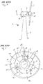
- FIG. 1 schematically shows a wind turbine 1.
- the wind turbine 1 comprises a tower 2, a nacelle 3 and a hub 4.
- the nacelle 3 is located on top of the tower 2.
- the hub 4 comprises a number of wind turbine blades 5.
- the hub 4 is mounted to the nacelle 3.
- the hub 4 is pivot-mounted such that it is able to rotate about a rotation axis 9.
- a generator 6 is located inside the nacelle 3.
- the wind turbine 1 is a direct drive wind turbine.
- the generator 6 comprises a near side 19 facing the hub 4 and a far side 20 opposite to the hub 4.
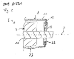
- FIG. 2 schematically shows part of a generator 6 with an outer rotor configuration in a sectional view.
- the generator 6 comprises a stator assembly 7 and a rotor assembly 8.
- the stator assembly 7 comprises a stationary shaft 10 which is located close to the rotation axis 9.
- the rotor assembly 8 comprises an outer rotor portion 11 which is located radially outward of the stator assembly 7.
- the rotor assembly 8 further comprises a brake disc 12.
- the brake disc 12 may be part of the outer rotor portion 11 or it may be connected to the outer rotor portion 11.
- the brake disc 12 extends radially inward from the outer portion 11 to the rotation axis 9.
- the outer portion 11 of the rotor assembly 8 and the brake disc 12 are pivot-mounted about the rotation axis 9.
- the stator assembly 7 further comprises a frictional member, in the present embodiment a brake calliper system 13.
- the brake calliper system 13 is operatively configured for frictionally engaging at least a portion of the brake disc 12.
- the brake calliper system 13 extends radially outward from the stationary shaft 10 to the brake disc 12.
- the brake calliper system 13 comprises at least one brake calliper on each side of the brake disc 12 in order to enclose the brake disc 12.
- the radial distance 22 between the brake disc 12 and the brake calliper system 13 is less than the radial distance 23 (air gap) between the outer rotor portion 11 and the stator assembly 7.
- radial distance 22 is between 1 mm and 5 mm, preferably between 2 mm and 4 mm.
- the air gap 23 has a width between 4 mm and 10 mm, advantageously between 5 mm and 7 mm.
- FIG. 3 schematically shows a front view of the inventive brake system of the generator 6. Elements which correspond to elements of the previously described Figures are designated with the same reference numerals and will not be described again in detail.
- the brake disc 12 comprises an inner surface 21.
- the inner surface 21 of the brake disc 12 comprises a number of recesses 15.
- the recesses 15 are radially and/or symmetrically spaced in the inner surface 21.
- the brake disc 12 can be divided into radial segments 12a, 12b and 12c.
- the brake disc 12 can also be divided into any other number of radial segments. This makes it possible to exchange a large brake disc 12 easily.
- the brake system further comprises a number of central mounted flanges 14, in the present embodiment three central mounted flanges 14.
- the flanges 14 are mounted to the stationary shaft 10.
- the flanges 14 are staggered about an angle of 120° regarding the circumference of the stationary shaft 10.
- any other number of the flanges 14 is possible.
- the flanges 14 are arranged around the circumference of the stationary shaft 10 such that adjacent flanges have an equal distance to each other.
- the brake system comprises at least one rotor lock system 17.
- the rotor lock system 17 comprises at least one piston 16.
- the piston is located inside the flange 14 or is located inside of a lock casing.
- the lock casing can be connected to the flange 14.
- the brake system can comprise separate flanges for housing the pistons or for being connected with at least one lock casing of the rotor lock system 17 and separate flanges 14 being connected with the brake system, especially the brake calliper system 13.
- the pistons 16 are located such that they are prepared to engage with the recesses 15 in the inner surface 21 of the brake disc 12.
- the rotor lock system 17 comprises an automatic actuator.
- the automatic actuator may be configured for actuating the rotor lock.
- the rotor lock system 17 may comprise an automatic actuator for pushing the pistons 16 into the corresponding recesses 15.
- the actuator comprises hydraulic or electrical means, for instance a hydraulic cylinder.
- recesses also holes can be present in the brake disc 12 and instead of pistons also pins may be used.
- rotor lock system 17 comprising a number of pistons 16
- a lock system comprising an interlock, a snap-in lock, a block, an arrest, a barricade or a similar means may be used.
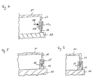
- Figure 4 schematically shows part of the inventive brake system in a sectional view along IV-IV of Figure 3 .
- two brake callipers 13A and 13B are located each on one side of the brake disc 12 opposite to each other.
- the two brake callipers 13A and 13B are connected to the central mounted flange 14.
- the flange 14 is connected to the stationary shaft 10.
- the brake disc is integrated part of the outer rotor portion 11.
- the brake disc 12 may be a separate element which is mounted to the outer rotor portion 11.
- the brake disc 12 can be fastened to a flange of a rotor support, for instance by bolts or screws.
- the actuation force for actuating the brake callipers 13A and 13B is designated by an error 18.
- the brake callipers 13A and 13B When the brake callipers 13A and 13B are actuated, they frictionally engage a portion of the brake disc 12.
- the wind turbine 1 may comprise a bed frame or a support structure of the stator.
- the brake calliper system 13 can be mounted directly to the bed frame of the wind turbine 1 or to the support structure of the stator.
- Figures 5 and 6 schematically show part of the inventive brake system in a sectional view along V-V of Figure 3 .
- the rotor lock system 17 is integrated into the brake system.
- Figure 5 schematically shows the rotor lock system in an unlocked state.
- Figure 6 shows the rotor lock system in a locked state.
- the piston 16 is completely located inside of the flange 14 or inside of another component of the rotor lock system 17, for example a lock casing.
- the piston 16 is pushed into a corresponding recess 15 of the brake disc 12. In this position the rotor is locked in a parking position.
- the piston 16 can be pushed into the corresponding recess 15 of the brake disc 12 by hydraulic or electrical means.
- the inventive brake system is located at the far side 20 of the generator 6 opposite to the hub 4. This allows for an easy access to the brake system and the integrated rotor lock system, especially for maintenance and service.
- the inventive brake system may be located at the hub.
- the inventive brake system may directly be connected to the hub.
- FIG. 7 schematically shows part of an inventive wind turbine 301. It comprises a typical and well known "one-bearing" arrangement.
- a wind turbine 301 comprises a direct drive generator 302, which is arranged on the upwind side of a tower 303 of the wind turbine 301.
- a tower flange 304 is arranged on the top of the tower 303.
- a bedplate 305 is attached to the tower flange 304.
- the wind turbine 401 comprises a yaw system - not shown here - which is used to turn the bedplate 305 of the wind turbine 301 around the axis 300.
- the wind turbine 301 comprises a stationary shaft 306, while the shaft 306 has a centre axis 200.
- the rear side of the stationary shaft 306 is attached to a retaining arrangement 307.
- a stator arrangement 308 of the direct drive generator 302 is arranged on the front side of the stationary shaft 306 .
- the stator arrangement 308 comprises a stator support structure 309 and a lamination stack 310.
- the lamination stack 310 supports windings 311.
- the stator support structure 309 comprises two support elements 312 for a two side support of the lamination stack 310.
- the support elements 312 are ring-shaped. They are attached to the outside of the stationary shaft 306.
- a hollow cylindrical support element 313 is attached to the outer ends of the ring-shaped support elements 312.
- the hollow cylindrical support element 313 carries the ring-shaped lamination stack 310 and the windings 311.
- a rotor arrangement 314 is arranged around the stator arrangement 308.
- the rotor arrangement 314 comprises a front endplate 315 and a cylinder element 317.
- the front endplate 315 is ring-shaped, while the cylinder element 317 is hollow.
- the cylinder element 317 comprises a plurality of permanent magnets 318, which are mounted on the inside of the hollow cylinder element 317.
- the permanent magnets 318 are arranged opposite to the lamination stack 310 and the supported windings.
- An air gap 319 with a width of approximately 6 mm is located between the permanent magnets 318 and the lamination stack 310.
- the air gap 319 has a width between 4 mm and 10 mm, advantageously between 5 mm and 7 mm.
- a brake disc 12 is connected to the cylinder element 317 of the rotor.
- a brake calliper system 13 is connected to the stationary shaft 306.
- the radial distance 22 between the brake calliper system 13 and the brake disc 12 is less than the air gap 319.
- radial distance 22 is between 1 mm and 5 mm, preferably between 2 mm and 4 mm.
- the front endplate 315 is arranged on the stationary shaft 306 via a bearing 320.
- the bearing 320 is capable to transform axial loads in both directions of the centre axis A.
- An appropriate bearing is disclosed in DE 201 16 649 U1 for example.
- the stationary part 321 of the bearing 320 is attached to the stationary shaft 306.
- the rotating part 322 of the bearing 320 is connected to a mounting ring 323.
- the front endplate 315 as well as the hub 324 are attached to the mounting ring 323.
- the hub 324 comprises mounting devices 325 for wind turbine rotor blades - not shown here.
- the air gap 319 shown here is uniform to achieve a constant distance between the elements of the rotor and the elements of the stator.
- the one bearing design is very attractive due to its easy design.
Abstract
Description
- The invention relates to a brake system, especially for a generator, a generator, especially a direct drive generator, and a wind turbine.
- In principle there are two main types of wind turbines in view of the direct drive configuration of a wind turbine. The first type of a wind turbine is the more classical type of a wind turbine comprising a gearbox arranged between a main shaft and a generator of the wind turbine. The second type of a wind turbine is a gearless type, where the gearbox and the conventional generator are substituted by a multipolar generator, a so called direct drive or directly driven generator. Such a direct drive generator can be made as a synchronous generator with winded rotor or with permanent magnets attached to the rotor, or it can be designed as an alternative type of a generator. One of the challenges with the direct drive generator is the mechanical brake system. The brake system needs to be located at the slowing rotating axis as no gear box is used. The brake system needs to withstand a large braking moment and large brake discs and callipers are necessary.
- The
US 2005/230979 describes a wind turbine which minimizes the size of the nacelle while providing adequate accessibility to components during maintenance operations. The wind turbine comprises: a nacelle and a blade rotor hub adjacent to said nacelle and a main shaft coupled to said hub and said nacelle. The generator is coupled to said shaft between said nacelle and said hub, wherein said generator includes generator rotor adjacent to said shaft, a stator positioned adjacent to and radially outward from said generator rotor; and a brake coupled to said generator and said shaft where the brake is positioned radially inward from said stator. The invention describes a solution that minimizes the brake system as the system can be more or less integrated into the generator. However, the proposed solution minimizes the size of the construction and also restricts the size of the brake system which is unwanted for a direct drive wind turbine where the size of the callipers and the brake disc should be as big as possible in order to withstand the high braking moments due to the slow rotational speed of the rotor. The brake system shown inUS 2005/230979 also prevents passage though the generator and it is not possible to go into the hub from the nacelle/generator. Furthermore, the invention relates to a generator with an inner rotor configuration and it not possible to use the configuration for brake system with outer rotor configuration. - In
US 2009/0026771 A1 a wind turbine comprising an electrical generator that includes a rotor assembly is disclosed. The wind turbine includes a frictional braking system for slowing, stopping or keeping stopped the rotation of the wind rotor and rotor assembly. In one implementation, the wind turbine/generator set includes a generator that includes a stator assembly and a rotor assembly rotatable about a rotational axis. The rotor assembly includes an active portion and an active portion support supporting the active portion. The wind turbine/generator set further includes a wind rotor coupled to the rotor assembly, a generator support fixedly supporting the stator assembly and rotatable supporting the rotor assembly. Furthermore, the wind turbine/generator set includes at least braking device fixed relative to the generator support. The braking device includes at least one frictional member operatively configured for frictionally engaging at least a portion of the active portion support. The rotor assembly is generally located radially inward of the stator assembly. - It is a first objective of the present invention to provide an advantageous brake system. It is a second objective of the present invention to provide an advantageous generator and it is a third objective of the present invention to provide an advantageous wind turbine.
- The first objective is solved by a brake system as claimed in
claim 1. The second objective is solved by a generator as claimed inclaim 13 and the third objective is solved by a wind turbine as claimed inclaim 15. The depending claims define further developments of the invention. - The inventive brake system comprises a rotor assembly, a stator assembly and a rotation axis. The rotor assembly comprises an outer portion which is located radially outward of the stator assembly. The outer portion comprises a brake disc. The stator assembly comprises at least one frictional member. The frictional member is operatively configured for frictionally engaging at least a portion of the brake disc. The inventive brake system may especially be used for a generator.
- The inventive brake system has the advantage, that the brake disc can be mounted on a cylindrical support structure of an outer rotor. In this case the possible large diameter of the machine can be fully used in order to use a brake disc with largest possible diameter. This increases the efficiency of the brake. Moreover, a bigger brake disc and bigger brake callipers can be used which provides a larger effective contact surface. A large effective contact surface is necessary in order to maintain the rotor in a parking position, for example. A further advantage is that more heat can be absorbed and distributed in a large brake disc compared with smaller brake discs.
- Generally, the inventive brake system can be part of a direct drive generator or it can be connected to a direct drive generator. The generator may have an outer rotor configuration.
- Advantageously the brake disc extends radially inward from the outer portion of the rotor assembly to the rotation axis. In this case the inventive brake system can be used for a direct drive generator. Furthermore, the inventive brake system may be part of a direct drive wind turbine with an outer rotor configuration.
- Moreover, the rotor assembly may comprise a flange. The brake disc may be fastened to the flange. For example, the flange may comprise a number of holes, preferably bolt holes. The holes may be radially spaced. Preferably the brake disc is fastened to the flange by bolts or screws.
- The brake system may be part of a wind turbine with a hub. In this case the brake system, especially the rotor assembly of the brake system, may comprise a near end which faces the hub and a far end which is located opposite to the hub. Preferably the flange, to which the brake disc is fastened, may be located at the fast end of the rotor assembly, which means opposite of the hub.
- The inventive brake system may comprise a rotor support. In this case the brake disc may be fastened to a flange of the rotor support, for example by bolts or screws.
- The stator assembly may comprise a stationary shaft. The at least one frictional member may be connected to the stationary shaft. The stator assembly may comprise a bed frame of a wind turbine. The at least one frictional member may be connected to the bed frame of the wind turbine. The stator assembly may comprise a stator support structure. The at least one frictional member may be connected to the stator support structure. For example, the at least one frictional member, for example at least one brake calliper, may be directly mounted to the stationary shaft or the bed frame of a wind turbine or a stator support structure.
- Preferably the at least one frictional member may extend radially outward regarding the rotation axis. For example, the at least one frictional member may extend radially outward from the stator support structure or from the stationary shaft or from the bed frame of a wind turbine.
- Especially, the frictional member may comprise at least one brake calliper. Preferably the frictional member comprises at least one brake calliper on each side of the brake disc, preferably in order to enclose the brake disc. Advantageously the at least one frictional member comprises at least one brake calliper system. The at least one calliper system may comprise at least to brake callipers located on each side of the brake disc opposite to each other. For example, the brake calliper system may comprise at least one calliper bracket. The calliper bracket may be used for mounting the callipers and/or the brake calliper system to another component of the brake system, for example for mounting to the stationary shaft. Each brake calliper system may be connected to a calliper bracket.
- Advantageously the brake calliper system may be designed such that it is aligned to the brake disc in axial direction in such a way that no bending moment, especially no axial bending moment, is experienced at a fixation point of the brake calliper system. For example, the brake calliper system may be aligned to the brake disc in axial direction or it may be configured in such a way that no bending moment or substantially no bending moment is experienced at a fixation point of the brake calliper system to the calliper brackets.
- Moreover, the inventive brake system may comprise a rotor lock system. Preferably, the rotor lock system is integrated in the brake system. Preferably, the rotor lock system comprises an automatic actuator. For example, the rotor lock system may comprise an interlock, a snap-in lock, a block, an arrest or a barricade, preferably a number of the afore mentioned components.
- The rotor lock system can be realised such that the brake disc comprises a number of recesses, preferably in the inner surface of the brake disc, for example radially and/or symmetrically spaced. The stator assembly may comprise at least one piston, preferably a number of pistons. Preferably, the piston/pistons is/are located such that it/they are prepared to engage with the recess/recesses. For example, the pistons or the piston are/is prepared to engage with the corresponding recesses in the brake disc in order to lock the rotor in a parking position.
- Preferably, the lock system may comprise an automatic actuator. The automatic actuator can advantageously be configured for pushing the pistons or the piston into the corresponding recesses. The actuator may comprise hydraulic or electrical means, for example a hydraulic cylinder. In this case the pistons can be pushed into the corresponding recesses of the brake disc by hydraulic or electrical means. This way, it is possible to lock the rotor in an automated manner.
- Furthermore, the brake disc may comprise a number of radial segments. If the brake disc is divided into radial segments it is possible to exchange a large brake disc in an easy way.
- The inventive generator comprises an inventive brake system as previously described. The inventive generator has the same advantages as the inventive brake system.
- Generally, the generator may have an air gap, which is located between stator elements and rotor elements of the generator. The rotor elements contain permanent magnets for example, while the stator elements contain stacked laminate plates, which support at least one winding of the stator coil.
- The air gap should be relatively small to ensure a high efficiency of the generator. Thus the air gap should stay in a range of only a few millimeters. For generators, like direct drive or directly driven generators, this is very difficult due to their size. Direct drive generators show a diameter of several meters.
- Rotor elements and stator elements are typically arranged opposite to each other, thus the air gap has to ensure that they do not come into contact while the generator is at operation. Thus the air gap should be very small to ensure the efficiency of the generator on the one hand while a certain width of the air gap is needed to prevent mechanical damages.
- Especially for a direct drive generator it is difficult to keep the air gap in a range of only a few millimeters. This requires therefore very rigid, massive and heavy support structures for the stator elements and for the rotor elements.
- The air gap of a generator can be determined by tolerances of the permanent magnets, which are part of the rotor, by tolerances of the stacked laminate-plates, which are part of the stator, and/or by tolerances of the coil-windings, which are part of the stator-coil. Also other elements of the generator contribute to the dimensions of the air gap. The air gap may be designed in a way that the elements of the rotor and of the stator do not get in contact, while the rotor rotates around its dedicated rotational axis.
- The inventive generator may comprise a rotor and a stator. Advantageously, the distance in radial direction (radial distance) between the brake disc and the frictional member is less than the distance in radial direction (radial distance) between the rotor and the stator. The frictional member can be the brake calliper or the brake calliper system or part of the brake calliper system, for instance a bracket. For example, the radial distance between the brake disc and the frictional member can be between 1mm and 5 mm, preferably between 2 mm and 4 mm. The radial distance between the rotor and the stator can be between 4 mm and 10 mm, preferably between 5 mm and 7 mm.
- If the radial distance between the brake disc and the frictional member is less than the radial distance between the rotor and the stator, the brake disc would hit the frictional member, for example the bracket of the brake calliper system, before the stator hits the rotor. This prevents damages to the generator and increases the safety of the system. The radial distance between rotor and stator is also called air gap. The generator may be part of a direct drive wind turbine with a unilateral bearing. The generator may comprises an unsupported end, which is the opposite end of where the bearing is located. By means of the inventive generator the air gap at the unsupported end can be maintained within the narrow tolerances.
- The inventive wind turbine comprises an inventive brake system and/or an inventive generator as previously described. The inventive wind turbine has the same advantageous as the inventive brake system and/or an inventive generator. Preferably the inventive wind turbine may be a direct drive wind turbine. Moreover, the inventive wind turbine may comprise an outer rotor configuration.
- The inventive wind turbine may comprise a nacelle, a hub and a generator. The generator may be located inside the nacelle or between the nacelle and the hub. The brake system may be connected to the generator and/or to the hub. For example, the brake system may be an integrated part of the generator and/or an integrated part of the hub.
- The generator may comprises a near side facing the hub and a far side opposite to the hub. Preferably the brake system and/or the lock system may be located at the far side opposite to the hub.
- Since the inventive brake system may be more or less an integrated part of the generator it does not take up extra space inside the nacelle. Moreover, entrance through the generator, especially through the stator, is possible, which is a great advantage. This provides easy access to the hub. Moreover, easy access to the parts of the brake system, especially if the brake system is located at the far side of the generator opposite to the hub, is provided. This allows for easier maintenance and service.
- Further features, properties and advantageous of the present invention will become clear from the following description of an embodiment in conjunction with the accompanying drawings. All features are advantageous alone or in combination with each other.
- Figure 1
- schematically shows a wind turbine.
- Figure 2
- schematically shows part of an inventive genrator with an inventive brake system in a sectional view.
- Figure 3
- schematically shows a front view of an inventive brake system.
- Figure 4
- schematically shows part of the inventive brake system in a sectional view along IV-IV of
Figure 3 . - Figure 5
- schematically shows part of the rotor lock system of the inventive brake system in a sectional view along V-V.
- Figure 6
- schematically shows the rotor lock system of
Figure 5 in a locked position. - Figure 7
- schematically shows part of an inventive wind turbine.
- An embodiment of the present invention will now be described with reference to
Figures 1 to 7 .Figure 1 schematically shows awind turbine 1. Thewind turbine 1 comprises atower 2, anacelle 3 and ahub 4. Thenacelle 3 is located on top of thetower 2. Thehub 4 comprises a number of wind turbine blades 5. Thehub 4 is mounted to thenacelle 3. Moreover, thehub 4 is pivot-mounted such that it is able to rotate about arotation axis 9. A generator 6 is located inside thenacelle 3. Thewind turbine 1 is a direct drive wind turbine. The generator 6 comprises anear side 19 facing thehub 4 and afar side 20 opposite to thehub 4. -
Figure 2 schematically shows part of a generator 6 with an outer rotor configuration in a sectional view. The generator 6 comprises a stator assembly 7 and arotor assembly 8. The stator assembly 7 comprises astationary shaft 10 which is located close to therotation axis 9. Therotor assembly 8 comprises anouter rotor portion 11 which is located radially outward of the stator assembly 7. Therotor assembly 8 further comprises abrake disc 12. Thebrake disc 12 may be part of theouter rotor portion 11 or it may be connected to theouter rotor portion 11. Thebrake disc 12 extends radially inward from theouter portion 11 to therotation axis 9. Theouter portion 11 of therotor assembly 8 and thebrake disc 12 are pivot-mounted about therotation axis 9. - The stator assembly 7 further comprises a frictional member, in the present embodiment a
brake calliper system 13. Thebrake calliper system 13 is operatively configured for frictionally engaging at least a portion of thebrake disc 12. Thebrake calliper system 13 extends radially outward from thestationary shaft 10 to thebrake disc 12. Thebrake calliper system 13 comprises at least one brake calliper on each side of thebrake disc 12 in order to enclose thebrake disc 12. - The
radial distance 22 between thebrake disc 12 and thebrake calliper system 13 is less than the radial distance 23 (air gap) between theouter rotor portion 11 and the stator assembly 7. Advantageously,radial distance 22 is between 1 mm and 5 mm, preferably between 2 mm and 4 mm. Preferably, theair gap 23 has a width between 4 mm and 10 mm, advantageously between 5 mm and 7 mm. -
Figure 3 schematically shows a front view of the inventive brake system of the generator 6. Elements which correspond to elements of the previously described Figures are designated with the same reference numerals and will not be described again in detail. Thebrake disc 12 comprises aninner surface 21. Theinner surface 21 of thebrake disc 12 comprises a number ofrecesses 15. Preferably therecesses 15 are radially and/or symmetrically spaced in theinner surface 21. - Generally, the
brake disc 12 can be divided intoradial segments 12a, 12b and 12c. Thebrake disc 12 can also be divided into any other number of radial segments. This makes it possible to exchange alarge brake disc 12 easily. - The brake system further comprises a number of central mounted
flanges 14, in the present embodiment three centralmounted flanges 14. Theflanges 14 are mounted to thestationary shaft 10. Theflanges 14 are staggered about an angle of 120° regarding the circumference of thestationary shaft 10. Alternatively any other number of theflanges 14 is possible. Preferably theflanges 14 are arranged around the circumference of thestationary shaft 10 such that adjacent flanges have an equal distance to each other. - The brake system comprises at least one
rotor lock system 17. Therotor lock system 17 comprises at least onepiston 16. The piston is located inside theflange 14 or is located inside of a lock casing. The lock casing can be connected to theflange 14. Alternatively, the brake system can comprise separate flanges for housing the pistons or for being connected with at least one lock casing of therotor lock system 17 andseparate flanges 14 being connected with the brake system, especially thebrake calliper system 13. - The
pistons 16 are located such that they are prepared to engage with therecesses 15 in theinner surface 21 of thebrake disc 12. Preferably, therotor lock system 17 comprises an automatic actuator. The automatic actuator may be configured for actuating the rotor lock. Especially, therotor lock system 17 may comprise an automatic actuator for pushing thepistons 16 into the corresponding recesses 15. Preferably the actuator comprises hydraulic or electrical means, for instance a hydraulic cylinder. Instead of recesses also holes can be present in thebrake disc 12 and instead of pistons also pins may be used. - Instead of the described
rotor lock system 17 comprising a number ofpistons 16 also a lock system comprising an interlock, a snap-in lock, a block, an arrest, a barricade or a similar means may be used. -
Figure 4 schematically shows part of the inventive brake system in a sectional view along IV-IV ofFigure 3 . InFigure 4 two brake callipers 13A and 13B are located each on one side of thebrake disc 12 opposite to each other. The two brake callipers 13A and 13B are connected to the central mountedflange 14. Theflange 14 is connected to thestationary shaft 10. InFigure 4 the brake disc is integrated part of theouter rotor portion 11. Alternatively, thebrake disc 12 may be a separate element which is mounted to theouter rotor portion 11. For example, thebrake disc 12 can be fastened to a flange of a rotor support, for instance by bolts or screws. - The actuation force for actuating the brake callipers 13A and 13B is designated by an
error 18. When the brake callipers 13A and 13B are actuated, they frictionally engage a portion of thebrake disc 12. - The
wind turbine 1 may comprise a bed frame or a support structure of the stator. In this case thebrake calliper system 13 can be mounted directly to the bed frame of thewind turbine 1 or to the support structure of the stator. -
Figures 5 and 6 schematically show part of the inventive brake system in a sectional view along V-V ofFigure 3 . In the present embodiment therotor lock system 17 is integrated into the brake system.Figure 5 schematically shows the rotor lock system in an unlocked state.Figure 6 shows the rotor lock system in a locked state. InFigure 5 thepiston 16 is completely located inside of theflange 14 or inside of another component of therotor lock system 17, for example a lock casing. InFigure 6 thepiston 16 is pushed into acorresponding recess 15 of thebrake disc 12. In this position the rotor is locked in a parking position. Thepiston 16 can be pushed into the correspondingrecess 15 of thebrake disc 12 by hydraulic or electrical means. - Preferably the inventive brake system is located at the
far side 20 of the generator 6 opposite to thehub 4. This allows for an easy access to the brake system and the integrated rotor lock system, especially for maintenance and service. Alternatively, the inventive brake system may be located at the hub. For example, the inventive brake system may directly be connected to the hub. -
Figure 7 schematically shows part of aninventive wind turbine 301. It comprises a typical and well known "one-bearing" arrangement. Awind turbine 301 comprises adirect drive generator 302, which is arranged on the upwind side of atower 303 of thewind turbine 301. - A
tower flange 304 is arranged on the top of thetower 303. Abedplate 305 is attached to thetower flange 304. The wind turbine 401 comprises a yaw system - not shown here - which is used to turn thebedplate 305 of thewind turbine 301 around theaxis 300. - The
wind turbine 301 comprises astationary shaft 306, while theshaft 306 has acentre axis 200. The rear side of thestationary shaft 306 is attached to a retainingarrangement 307. On the front side of the stationary shaft 306 astator arrangement 308 of thedirect drive generator 302 is arranged. Thestator arrangement 308 comprises a stator support structure 309 and a lamination stack 310. The lamination stack 310 supports windings 311. - The stator support structure 309 comprises two
support elements 312 for a two side support of the lamination stack 310. Thesupport elements 312 are ring-shaped. They are attached to the outside of thestationary shaft 306. A hollowcylindrical support element 313 is attached to the outer ends of the ring-shapedsupport elements 312. The hollowcylindrical support element 313 carries the ring-shaped lamination stack 310 and the windings 311. - A
rotor arrangement 314 is arranged around thestator arrangement 308. Therotor arrangement 314 comprises afront endplate 315 and acylinder element 317. Thefront endplate 315 is ring-shaped, while thecylinder element 317 is hollow. - The
cylinder element 317 comprises a plurality ofpermanent magnets 318, which are mounted on the inside of thehollow cylinder element 317. Thepermanent magnets 318 are arranged opposite to the lamination stack 310 and the supported windings. Anair gap 319 with a width of approximately 6 mm is located between thepermanent magnets 318 and the lamination stack 310. Preferably, theair gap 319 has a width between 4 mm and 10 mm, advantageously between 5 mm and 7 mm. Abrake disc 12 is connected to thecylinder element 317 of the rotor. Abrake calliper system 13 is connected to thestationary shaft 306. Theradial distance 22 between thebrake calliper system 13 and thebrake disc 12 is less than theair gap 319. Advantageously,radial distance 22 is between 1 mm and 5 mm, preferably between 2 mm and 4 mm. - The
front endplate 315 is arranged on thestationary shaft 306 via abearing 320. Thebearing 320 is capable to transform axial loads in both directions of the centre axis A. An appropriate bearing is disclosed inDE 201 16 649 U1 for example. - The
stationary part 321 of thebearing 320 is attached to thestationary shaft 306. Therotating part 322 of thebearing 320 is connected to a mountingring 323. Thefront endplate 315 as well as thehub 324 are attached to the mountingring 323. Thehub 324 comprises mountingdevices 325 for wind turbine rotor blades - not shown here. - The
air gap 319 shown here is uniform to achieve a constant distance between the elements of the rotor and the elements of the stator. The one bearing design is very attractive due to its easy design.
Claims (16)
- A brake system, comprising a rotor assembly (8), a stator assembly (7) and a rotation axis (9),
wherein the rotor assembly (8) comprises an outer portion (11) which is located radially outward of the stator assembly (7), the outer portion (11) comprises a brake disc (12), and the stator assembly (7) comprises at least one frictional member (13) operatively configured for frictionally engaging at least a portion of the brake disc (12). - The brake system as claimed in claim 1,
wherein the brake disc (12) extends radially inward from the outer portion (11) of the rotor assembly (8) to the rotation axis (9) . - The brake system as claimed in claim 1 or 2,
wherein the rotor assembly (8) comprises a flange (14) and the brake disc (12) is fastened to the flange (14). - The brake system as claimed in any of the claims 1 to 3, wherein the stator assembly (7) comprises a stationary shaft (10) or a bed frame of a wind turbine (1) or a stator support structure and the at least one frictional member (13) is connected to the stationary shaft (10) or to the bed frame or to the stator support structure.
- The brake system as claimed in any of the claims 1 to 4, wherein the at least one frictional member (13) extends radially outward regarding the rotation axis (9).
- The brake system as claimed in any of the claims 2 to 5, wherein the frictional member (13) comprises at least one brake calliper.
- The brake system as claimed in any of the claims 1 to 6, wherein the at least one frictional member (13) comprises at least one brake calliper system, which comprises at least two brake callipers located on each side of the brake disc (12) opposite to each other.
- The brake system as claimed in claim 7,
wherein the at least one brake calliper system (13) is aligned to the brake disc (12) in axial direction in such a way that no bending moment is experienced at a fixation point of the brake calliper system (13). - The brake system as claimed in any of the claims 1 to 8, wherein the brake system comprises a rotor lock system (17).
- The brake system as claimed in claim 9,
wherein the brake disc (12) comprises a number of recesses (15) and the stator assembly (7) comprises at least one pistons (16) which is located such that it is prepared to engage with the recesses (15). - The brake system as claimed in claim 10,
wherein the lock system (17) comprises an automatic actuator for pushing the piston (16) into the corresponding recess (15). - The brake system as claimed in any of the claims 1 to 11, wherein the brake disc (12) comprises a number of radial segments (12a, 12b, 12c).
- A generator (6) comprising a brake system as claimed in any of the claims 1 to 12.
- The generator (6) as claimed in claim 13,
wherein the generator (6) comprises a rotor and a stator and the radial distance (22) between the brake disc (12) and the frictional member (13) is less than the radial distance (23) between the rotor and the stator. - A wind turbine (1) comprising a brake system as claimed in any of the claims 1 to 12 and/or a generator as claimed in claim 13 or 14.
- The wind turbine (1) as claimed in claim 15,
wherein the wind turbine (1) comprises a generator (6) and/or a hub (4) and the brake system is connected to the generator (6) and/or to the hub (4).
Priority Applications (7)
| Application Number | Priority Date | Filing Date | Title |
|---|---|---|---|
| DK09014766.1T DK2333325T3 (en) | 2009-11-26 | 2009-11-26 | Brake system, wind turbine generator and |
| EP09014766.1A EP2333325B1 (en) | 2009-11-26 | 2009-11-26 | Brake system, generator and wind turbine |
| US12/951,414 US9906099B2 (en) | 2009-11-26 | 2010-11-22 | Brake system, generator and wind turbine |
| CA2722501A CA2722501C (en) | 2009-11-26 | 2010-11-24 | Brake system, generator and wind turbine |
| NZ589529A NZ589529A (en) | 2009-11-26 | 2010-11-25 | Brake system, generator and wind turbine |
| JP2010263889A JP5717413B2 (en) | 2009-11-26 | 2010-11-26 | Brake system, generator, and windmill |
| CN201010565611.2A CN102080630B (en) | 2009-11-26 | 2010-11-26 | Brake system, generator and wind turbine |
Applications Claiming Priority (1)
| Application Number | Priority Date | Filing Date | Title |
|---|---|---|---|
| EP09014766.1A EP2333325B1 (en) | 2009-11-26 | 2009-11-26 | Brake system, generator and wind turbine |
Publications (2)
| Publication Number | Publication Date |
|---|---|
| EP2333325A1 true EP2333325A1 (en) | 2011-06-15 |
| EP2333325B1 EP2333325B1 (en) | 2015-06-24 |
Family
ID=42634903
Family Applications (1)
| Application Number | Title | Priority Date | Filing Date |
|---|---|---|---|
| EP09014766.1A Active EP2333325B1 (en) | 2009-11-26 | 2009-11-26 | Brake system, generator and wind turbine |
Country Status (7)
| Country | Link |
|---|---|
| US (1) | US9906099B2 (en) |
| EP (1) | EP2333325B1 (en) |
| JP (1) | JP5717413B2 (en) |
| CN (1) | CN102080630B (en) |
| CA (1) | CA2722501C (en) |
| DK (1) | DK2333325T3 (en) |
| NZ (1) | NZ589529A (en) |
Cited By (4)
| Publication number | Priority date | Publication date | Assignee | Title |
|---|---|---|---|---|
| EP2669510A1 (en) | 2012-05-30 | 2013-12-04 | Siemens Aktiengesellschaft | A brake system for a wind turbine |
| CN103867385A (en) * | 2012-12-18 | 2014-06-18 | 西门子公司 | Air-gap secure system for wind turbine |
| WO2014146764A1 (en) * | 2013-03-18 | 2014-09-25 | Wind-Direct Gmbh | Method for stopping a wind turbine and wind turbine for performing the method |
| DE102018100864A1 (en) | 2018-01-16 | 2019-07-18 | Wobben Properties Gmbh | Wind turbine with a braking and locking device, stand assembly for selbige, and method for their operation |
Families Citing this family (15)
| Publication number | Priority date | Publication date | Assignee | Title |
|---|---|---|---|---|
| GB2461285B (en) * | 2008-06-26 | 2012-07-25 | Converteam Technology Ltd | Vertical axis wind turbines |
| CN101482097B (en) * | 2009-01-21 | 2012-01-25 | 严强 | Braking system and braking method used for vertical axis aerogenerator |
| EP2437380A1 (en) * | 2010-09-30 | 2012-04-04 | Siemens Aktiengesellschaft | Rotor, generator and wind turbine |
| CN103354872B (en) * | 2011-01-05 | 2016-01-20 | 维斯塔斯风力系统有限公司 | Direct drive generator |
| EP2584673A1 (en) * | 2011-10-17 | 2013-04-24 | ABB Oy | Electric machine with dampening means |
| DE102012208550A1 (en) * | 2012-05-22 | 2013-11-28 | Wobben Properties Gmbh | Generator of a gearless wind turbine |
| EP2690284B1 (en) * | 2012-07-23 | 2015-08-26 | Siemens Aktiengesellschaft | Wind turbine generator and maintenance of its main bearing |
| DE102012215575A1 (en) * | 2012-09-03 | 2014-03-06 | Wobben Properties Gmbh | Method and control device for a wind energy plant and computer program product, digital storage medium and wind energy plant |
| AU2014257722A1 (en) * | 2013-04-23 | 2015-12-03 | youWINenergy GmbH | Wind turbine architecture |
| EP2896824B1 (en) * | 2014-01-20 | 2016-06-01 | Siemens Aktiengesellschaft | Brake system for a wind turbine generator |
| KR101763641B1 (en) * | 2016-01-05 | 2017-08-01 | 손정봉 | Wind power generator |
| CN110195685B (en) * | 2019-05-27 | 2020-11-27 | 上海电气风电集团股份有限公司 | Brake system and outer rotor type direct-drive wind generating set |
| CN110425235A (en) * | 2019-08-29 | 2019-11-08 | 中国华能集团清洁能源技术研究院有限公司 | A kind of wind-driven generator braking device |
| CN112664392A (en) | 2019-10-15 | 2021-04-16 | 通用电气公司 | System and method for locking wind turbine rotor during extended maintenance |
| CN113217284B (en) * | 2021-05-17 | 2022-07-22 | 广州赛特新能源科技发展有限公司 | Direct-drive breeze wind driven generator system |
Citations (4)
| Publication number | Priority date | Publication date | Assignee | Title |
|---|---|---|---|---|
| US20040120820A1 (en) * | 2002-01-24 | 2004-06-24 | Jacquelin Dery | Vertical axis windmill and self-erecting structure therefor |
| US20050230979A1 (en) | 2004-04-19 | 2005-10-20 | Northern Power Systems | Direct Drive Wind Turbine |
| EP1925820A1 (en) * | 2006-11-23 | 2008-05-28 | Harakosan Co. Ltd. | Wind turbine main bearing |
| US7431567B1 (en) * | 2003-05-30 | 2008-10-07 | Northern Power Systems Inc. | Wind turbine having a direct-drive drivetrain |
Family Cites Families (16)
| Publication number | Priority date | Publication date | Assignee | Title |
|---|---|---|---|---|
| US3718210A (en) * | 1970-06-24 | 1973-02-27 | Goodyear Tire & Rubber | Rotating brake disc subassembly with segmented beryllium core |
| JPS6381338U (en) | 1986-11-17 | 1988-05-28 | ||
| JPH08200203A (en) * | 1995-01-25 | 1996-08-06 | Mitsubishi Heavy Ind Ltd | Windmill speed-increasing gear protection device |
| JPH10184740A (en) | 1996-12-18 | 1998-07-14 | Akebono Brake Ind Co Ltd | Twin-caliper type disk brake device |
| FR2810374B1 (en) * | 2000-06-19 | 2004-09-03 | Jeumont Ind | DEVICE FOR PRODUCING ELECTRIC CURRENT FROM WIND ENERGY |
| US6749399B2 (en) | 2002-03-07 | 2004-06-15 | Ocean Wind Energy Systems | Vertical array wind turbine |
| US7042109B2 (en) * | 2002-08-30 | 2006-05-09 | Gabrys Christopher W | Wind turbine |
| JP2004312845A (en) * | 2003-04-04 | 2004-11-04 | Nissan Motor Co Ltd | Stator for motor |
| JP4391884B2 (en) | 2004-05-26 | 2009-12-24 | 本田技研工業株式会社 | Wheel drive device for vehicle |
| US7467530B2 (en) * | 2005-07-29 | 2008-12-23 | New Hampton Technologies Llc | Vehicle lock |
| JP2007211875A (en) | 2006-02-09 | 2007-08-23 | Hino Motors Ltd | Parking braking device of disc brake vehicle |
| EP2327873A1 (en) * | 2006-04-28 | 2011-06-01 | Swanturbines Limited | Tidal current turbine |
| US7431557B2 (en) * | 2006-05-25 | 2008-10-07 | General Electric Company | Compensating for blade tip clearance deterioration in active clearance control |
| JP5110854B2 (en) | 2006-11-17 | 2012-12-26 | Ntn株式会社 | Wheel bearing device with in-wheel motor built-in sensor |
| US7821164B2 (en) * | 2007-02-15 | 2010-10-26 | General Electric Company | Method and apparatus for a superconducting generator driven by wind turbine |
| JP5045140B2 (en) | 2007-02-19 | 2012-10-10 | 澁谷工業株式会社 | Electron beam sterilization system |
-
2009
- 2009-11-26 EP EP09014766.1A patent/EP2333325B1/en active Active
- 2009-11-26 DK DK09014766.1T patent/DK2333325T3/en active
-
2010
- 2010-11-22 US US12/951,414 patent/US9906099B2/en active Active
- 2010-11-24 CA CA2722501A patent/CA2722501C/en not_active Expired - Fee Related
- 2010-11-25 NZ NZ589529A patent/NZ589529A/en not_active IP Right Cessation
- 2010-11-26 JP JP2010263889A patent/JP5717413B2/en active Active
- 2010-11-26 CN CN201010565611.2A patent/CN102080630B/en active Active
Patent Citations (5)
| Publication number | Priority date | Publication date | Assignee | Title |
|---|---|---|---|---|
| US20040120820A1 (en) * | 2002-01-24 | 2004-06-24 | Jacquelin Dery | Vertical axis windmill and self-erecting structure therefor |
| US7431567B1 (en) * | 2003-05-30 | 2008-10-07 | Northern Power Systems Inc. | Wind turbine having a direct-drive drivetrain |
| US20090026771A1 (en) | 2003-05-30 | 2009-01-29 | Northern Power Systems, Inc. | Wind Turbine Having a Direct-Drive Drivetrain |
| US20050230979A1 (en) | 2004-04-19 | 2005-10-20 | Northern Power Systems | Direct Drive Wind Turbine |
| EP1925820A1 (en) * | 2006-11-23 | 2008-05-28 | Harakosan Co. Ltd. | Wind turbine main bearing |
Cited By (8)
| Publication number | Priority date | Publication date | Assignee | Title |
|---|---|---|---|---|
| EP2669510A1 (en) | 2012-05-30 | 2013-12-04 | Siemens Aktiengesellschaft | A brake system for a wind turbine |
| CN103867385A (en) * | 2012-12-18 | 2014-06-18 | 西门子公司 | Air-gap secure system for wind turbine |
| EP2747252A1 (en) * | 2012-12-18 | 2014-06-25 | Siemens Aktiengesellschaft | Air-gap secure system for a wind turbine |
| CN103867385B (en) * | 2012-12-18 | 2018-09-14 | 西门子公司 | The air gap security system for wind turbine |
| WO2014146764A1 (en) * | 2013-03-18 | 2014-09-25 | Wind-Direct Gmbh | Method for stopping a wind turbine and wind turbine for performing the method |
| US9777710B2 (en) | 2013-03-18 | 2017-10-03 | Wind-Direct Gmbh | Method for stopping and locking a wind turbine rotor by short-circuiting generator stator windings |
| DE102018100864A1 (en) | 2018-01-16 | 2019-07-18 | Wobben Properties Gmbh | Wind turbine with a braking and locking device, stand assembly for selbige, and method for their operation |
| WO2019141643A1 (en) | 2018-01-16 | 2019-07-25 | Wobben Properties Gmbh | Wind turbine having a braking and arresting device, static assembly for same, and method for operating same |
Also Published As
| Publication number | Publication date |
|---|---|
| CA2722501C (en) | 2018-10-16 |
| DK2333325T3 (en) | 2015-08-24 |
| JP2011112227A (en) | 2011-06-09 |
| NZ589529A (en) | 2011-07-29 |
| US9906099B2 (en) | 2018-02-27 |
| CN102080630B (en) | 2014-11-26 |
| CA2722501A1 (en) | 2011-05-26 |
| US20110121579A1 (en) | 2011-05-26 |
| EP2333325B1 (en) | 2015-06-24 |
| JP5717413B2 (en) | 2015-05-13 |
| CN102080630A (en) | 2011-06-01 |
Similar Documents
| Publication | Publication Date | Title |
|---|---|---|
| EP2333325B1 (en) | Brake system, generator and wind turbine | |
| EP2333326B1 (en) | Brake system for a wind turbine with integrated rotor lock, generator and wind turbine | |
| EP2143936B1 (en) | Wind turbine comprising a main bearing and method for replacement of the main bearing | |
| US20120181792A1 (en) | Wind turbine | |
| US8975770B2 (en) | Wind power turbine electric generator and wind power turbine equipped with an electric generator | |
| KR20030011902A (en) | Device for producing electric current from wind energy | |
| CN107294273B (en) | Control of the rotational movement of a generator by means of a turning device | |
| KR20140108733A (en) | Wind turbine rotor | |
| US8684672B2 (en) | Brake system with expansion absorbing means, generator and wind turbine | |
| US20120080969A1 (en) | Rotor, generator and wind turbine | |
| EP2896824B1 (en) | Brake system for a wind turbine generator | |
| EP3226384A1 (en) | Rotational movement control of an electric generator by means of a turning device | |
| US20190195197A1 (en) | Rotor arresting device for a wind turbine and method |
Legal Events
| Date | Code | Title | Description |
|---|---|---|---|
| PUAI | Public reference made under article 153(3) epc to a published international application that has entered the european phase |
Free format text: ORIGINAL CODE: 0009012 |
|
| AK | Designated contracting states |
Kind code of ref document: A1 Designated state(s): AT BE BG CH CY CZ DE DK EE ES FI FR GB GR HR HU IE IS IT LI LT LU LV MC MK MT NL NO PL PT RO SE SI SK SM TR |
|
| AX | Request for extension of the european patent |
Extension state: AL BA RS |
|
| 17P | Request for examination filed |
Effective date: 20110704 |
|
| 17Q | First examination report despatched |
Effective date: 20130109 |
|
| RAP1 | Party data changed (applicant data changed or rights of an application transferred) |
Owner name: SIEMENS AKTIENGESELLSCHAFT |
|
| RIC1 | Information provided on ipc code assigned before grant |
Ipc: F03D 11/00 20060101ALI20141208BHEP Ipc: F03D 7/02 20060101ALI20141208BHEP Ipc: H02K 7/102 20060101ALI20141208BHEP Ipc: H02K 7/18 20060101ALI20141208BHEP Ipc: F03D 9/00 20060101AFI20141208BHEP |
|
| GRAP | Despatch of communication of intention to grant a patent |
Free format text: ORIGINAL CODE: EPIDOSNIGR1 |
|
| INTG | Intention to grant announced |
Effective date: 20150204 |
|
| GRAS | Grant fee paid |
Free format text: ORIGINAL CODE: EPIDOSNIGR3 |
|
| GRAA | (expected) grant |
Free format text: ORIGINAL CODE: 0009210 |
|
| AK | Designated contracting states |
Kind code of ref document: B1 Designated state(s): AT BE BG CH CY CZ DE DK EE ES FI FR GB GR HR HU IE IS IT LI LT LU LV MC MK MT NL NO PL PT RO SE SI SK SM TR |
|
| REG | Reference to a national code |
Ref country code: GB Ref legal event code: FG4D |
|
| REG | Reference to a national code |
Ref country code: CH Ref legal event code: EP |
|
| REG | Reference to a national code |
Ref country code: AT Ref legal event code: REF Ref document number: 733026 Country of ref document: AT Kind code of ref document: T Effective date: 20150715 |
|
| REG | Reference to a national code |
Ref country code: IE Ref legal event code: FG4D |
|
| REG | Reference to a national code |
Ref country code: DE Ref legal event code: R096 Ref document number: 602009031823 Country of ref document: DE |
|
| REG | Reference to a national code |
Ref country code: DK Ref legal event code: T3 Effective date: 20150820 |
|
| PG25 | Lapsed in a contracting state [announced via postgrant information from national office to epo] |
Ref country code: NO Free format text: LAPSE BECAUSE OF FAILURE TO SUBMIT A TRANSLATION OF THE DESCRIPTION OR TO PAY THE FEE WITHIN THE PRESCRIBED TIME-LIMIT Effective date: 20150924 Ref country code: FI Free format text: LAPSE BECAUSE OF FAILURE TO SUBMIT A TRANSLATION OF THE DESCRIPTION OR TO PAY THE FEE WITHIN THE PRESCRIBED TIME-LIMIT Effective date: 20150624 Ref country code: LT Free format text: LAPSE BECAUSE OF FAILURE TO SUBMIT A TRANSLATION OF THE DESCRIPTION OR TO PAY THE FEE WITHIN THE PRESCRIBED TIME-LIMIT Effective date: 20150624 Ref country code: HR Free format text: LAPSE BECAUSE OF FAILURE TO SUBMIT A TRANSLATION OF THE DESCRIPTION OR TO PAY THE FEE WITHIN THE PRESCRIBED TIME-LIMIT Effective date: 20150624 |
|
| REG | Reference to a national code |
Ref country code: AT Ref legal event code: MK05 Ref document number: 733026 Country of ref document: AT Kind code of ref document: T Effective date: 20150624 |
|
| REG | Reference to a national code |
Ref country code: LT Ref legal event code: MG4D |
|
| PG25 | Lapsed in a contracting state [announced via postgrant information from national office to epo] |
Ref country code: LV Free format text: LAPSE BECAUSE OF FAILURE TO SUBMIT A TRANSLATION OF THE DESCRIPTION OR TO PAY THE FEE WITHIN THE PRESCRIBED TIME-LIMIT Effective date: 20150624 Ref country code: BG Free format text: LAPSE BECAUSE OF FAILURE TO SUBMIT A TRANSLATION OF THE DESCRIPTION OR TO PAY THE FEE WITHIN THE PRESCRIBED TIME-LIMIT Effective date: 20150924 Ref country code: GR Free format text: LAPSE BECAUSE OF FAILURE TO SUBMIT A TRANSLATION OF THE DESCRIPTION OR TO PAY THE FEE WITHIN THE PRESCRIBED TIME-LIMIT Effective date: 20150925 |
|
| REG | Reference to a national code |
Ref country code: NL Ref legal event code: MP Effective date: 20150624 |
|
| PG25 | Lapsed in a contracting state [announced via postgrant information from national office to epo] |
Ref country code: EE Free format text: LAPSE BECAUSE OF FAILURE TO SUBMIT A TRANSLATION OF THE DESCRIPTION OR TO PAY THE FEE WITHIN THE PRESCRIBED TIME-LIMIT Effective date: 20150624 |
|
| PG25 | Lapsed in a contracting state [announced via postgrant information from national office to epo] |
Ref country code: IS Free format text: LAPSE BECAUSE OF FAILURE TO SUBMIT A TRANSLATION OF THE DESCRIPTION OR TO PAY THE FEE WITHIN THE PRESCRIBED TIME-LIMIT Effective date: 20151024 Ref country code: CZ Free format text: LAPSE BECAUSE OF FAILURE TO SUBMIT A TRANSLATION OF THE DESCRIPTION OR TO PAY THE FEE WITHIN THE PRESCRIBED TIME-LIMIT Effective date: 20150624 Ref country code: RO Free format text: LAPSE BECAUSE OF NON-PAYMENT OF DUE FEES Effective date: 20150624 Ref country code: PT Free format text: LAPSE BECAUSE OF FAILURE TO SUBMIT A TRANSLATION OF THE DESCRIPTION OR TO PAY THE FEE WITHIN THE PRESCRIBED TIME-LIMIT Effective date: 20151026 Ref country code: SK Free format text: LAPSE BECAUSE OF FAILURE TO SUBMIT A TRANSLATION OF THE DESCRIPTION OR TO PAY THE FEE WITHIN THE PRESCRIBED TIME-LIMIT Effective date: 20150624 Ref country code: PL Free format text: LAPSE BECAUSE OF FAILURE TO SUBMIT A TRANSLATION OF THE DESCRIPTION OR TO PAY THE FEE WITHIN THE PRESCRIBED TIME-LIMIT Effective date: 20150624 Ref country code: ES Free format text: LAPSE BECAUSE OF FAILURE TO SUBMIT A TRANSLATION OF THE DESCRIPTION OR TO PAY THE FEE WITHIN THE PRESCRIBED TIME-LIMIT Effective date: 20150624 Ref country code: AT Free format text: LAPSE BECAUSE OF FAILURE TO SUBMIT A TRANSLATION OF THE DESCRIPTION OR TO PAY THE FEE WITHIN THE PRESCRIBED TIME-LIMIT Effective date: 20150624 |
|
| REG | Reference to a national code |
Ref country code: DE Ref legal event code: R097 Ref document number: 602009031823 Country of ref document: DE |
|
| PG25 | Lapsed in a contracting state [announced via postgrant information from national office to epo] |
Ref country code: IT Free format text: LAPSE BECAUSE OF FAILURE TO SUBMIT A TRANSLATION OF THE DESCRIPTION OR TO PAY THE FEE WITHIN THE PRESCRIBED TIME-LIMIT Effective date: 20150624 |
|
| PLBE | No opposition filed within time limit |
Free format text: ORIGINAL CODE: 0009261 |
|
| STAA | Information on the status of an ep patent application or granted ep patent |
Free format text: STATUS: NO OPPOSITION FILED WITHIN TIME LIMIT |
|
| 26N | No opposition filed |
Effective date: 20160329 |
|
| PG25 | Lapsed in a contracting state [announced via postgrant information from national office to epo] |
Ref country code: LU Free format text: LAPSE BECAUSE OF FAILURE TO SUBMIT A TRANSLATION OF THE DESCRIPTION OR TO PAY THE FEE WITHIN THE PRESCRIBED TIME-LIMIT Effective date: 20151126 Ref country code: MC Free format text: LAPSE BECAUSE OF FAILURE TO SUBMIT A TRANSLATION OF THE DESCRIPTION OR TO PAY THE FEE WITHIN THE PRESCRIBED TIME-LIMIT Effective date: 20150624 |
|
| REG | Reference to a national code |
Ref country code: CH Ref legal event code: PL |
|
| PG25 | Lapsed in a contracting state [announced via postgrant information from national office to epo] |
Ref country code: CH Free format text: LAPSE BECAUSE OF NON-PAYMENT OF DUE FEES Effective date: 20151130 Ref country code: LI Free format text: LAPSE BECAUSE OF NON-PAYMENT OF DUE FEES Effective date: 20151130 |
|
| REG | Reference to a national code |
Ref country code: IE Ref legal event code: MM4A |
|
| REG | Reference to a national code |
Ref country code: FR Ref legal event code: ST Effective date: 20160729 |
|
| PG25 | Lapsed in a contracting state [announced via postgrant information from national office to epo] |
Ref country code: SI Free format text: LAPSE BECAUSE OF FAILURE TO SUBMIT A TRANSLATION OF THE DESCRIPTION OR TO PAY THE FEE WITHIN THE PRESCRIBED TIME-LIMIT Effective date: 20150624 |
|
| PG25 | Lapsed in a contracting state [announced via postgrant information from national office to epo] |
Ref country code: IE Free format text: LAPSE BECAUSE OF NON-PAYMENT OF DUE FEES Effective date: 20151126 |
|
| PG25 | Lapsed in a contracting state [announced via postgrant information from national office to epo] |
Ref country code: FR Free format text: LAPSE BECAUSE OF NON-PAYMENT OF DUE FEES Effective date: 20151130 |
|
| PG25 | Lapsed in a contracting state [announced via postgrant information from national office to epo] |
Ref country code: BE Free format text: LAPSE BECAUSE OF FAILURE TO SUBMIT A TRANSLATION OF THE DESCRIPTION OR TO PAY THE FEE WITHIN THE PRESCRIBED TIME-LIMIT Effective date: 20150624 |
|
| PG25 | Lapsed in a contracting state [announced via postgrant information from national office to epo] |
Ref country code: SM Free format text: LAPSE BECAUSE OF FAILURE TO SUBMIT A TRANSLATION OF THE DESCRIPTION OR TO PAY THE FEE WITHIN THE PRESCRIBED TIME-LIMIT Effective date: 20150624 Ref country code: HU Free format text: LAPSE BECAUSE OF FAILURE TO SUBMIT A TRANSLATION OF THE DESCRIPTION OR TO PAY THE FEE WITHIN THE PRESCRIBED TIME-LIMIT; INVALID AB INITIO Effective date: 20091126 |
|
| PG25 | Lapsed in a contracting state [announced via postgrant information from national office to epo] |
Ref country code: NL Free format text: LAPSE BECAUSE OF FAILURE TO SUBMIT A TRANSLATION OF THE DESCRIPTION OR TO PAY THE FEE WITHIN THE PRESCRIBED TIME-LIMIT Effective date: 20150624 Ref country code: SE Free format text: LAPSE BECAUSE OF FAILURE TO SUBMIT A TRANSLATION OF THE DESCRIPTION OR TO PAY THE FEE WITHIN THE PRESCRIBED TIME-LIMIT Effective date: 20150624 Ref country code: CY Free format text: LAPSE BECAUSE OF FAILURE TO SUBMIT A TRANSLATION OF THE DESCRIPTION OR TO PAY THE FEE WITHIN THE PRESCRIBED TIME-LIMIT Effective date: 20150624 |
|
| PG25 | Lapsed in a contracting state [announced via postgrant information from national office to epo] |
Ref country code: TR Free format text: LAPSE BECAUSE OF FAILURE TO SUBMIT A TRANSLATION OF THE DESCRIPTION OR TO PAY THE FEE WITHIN THE PRESCRIBED TIME-LIMIT Effective date: 20150624 Ref country code: MT Free format text: LAPSE BECAUSE OF FAILURE TO SUBMIT A TRANSLATION OF THE DESCRIPTION OR TO PAY THE FEE WITHIN THE PRESCRIBED TIME-LIMIT Effective date: 20150624 |
|
| PG25 | Lapsed in a contracting state [announced via postgrant information from national office to epo] |
Ref country code: MK Free format text: LAPSE BECAUSE OF FAILURE TO SUBMIT A TRANSLATION OF THE DESCRIPTION OR TO PAY THE FEE WITHIN THE PRESCRIBED TIME-LIMIT Effective date: 20150624 |
|
| REG | Reference to a national code |
Ref country code: DE Ref legal event code: R081 Ref document number: 602009031823 Country of ref document: DE Owner name: SIEMENS GAMESA RENEWABLE ENERGY A/S, DK Free format text: FORMER OWNER: SIEMENS AKTIENGESELLSCHAFT, 80333 MUENCHEN, DE |
|
| REG | Reference to a national code |
Ref country code: GB Ref legal event code: 732E Free format text: REGISTERED BETWEEN 20191128 AND 20191204 |
|
| PGFP | Annual fee paid to national office [announced via postgrant information from national office to epo] |
Ref country code: GB Payment date: 20221123 Year of fee payment: 14 Ref country code: DK Payment date: 20221122 Year of fee payment: 14 Ref country code: DE Payment date: 20221121 Year of fee payment: 14 |