EP2292926A1 - Wind generator blade with hyper-supporting elements - Google Patents
Wind generator blade with hyper-supporting elements Download PDFInfo
- Publication number
- EP2292926A1 EP2292926A1 EP20090754010 EP09754010A EP2292926A1 EP 2292926 A1 EP2292926 A1 EP 2292926A1 EP 20090754010 EP20090754010 EP 20090754010 EP 09754010 A EP09754010 A EP 09754010A EP 2292926 A1 EP2292926 A1 EP 2292926A1
- Authority
- EP
- European Patent Office
- Prior art keywords
- blade
- lift device
- root
- leading edge
- lift
- Prior art date
- Legal status (The legal status is an assumption and is not a legal conclusion. Google has not performed a legal analysis and makes no representation as to the accuracy of the status listed.)
- Granted
Links
- 238000009434 installation Methods 0.000 description 1
- 230000004048 modification Effects 0.000 description 1
- 238000012986 modification Methods 0.000 description 1
Images

Classifications
-
- F—MECHANICAL ENGINEERING; LIGHTING; HEATING; WEAPONS; BLASTING
- F03—MACHINES OR ENGINES FOR LIQUIDS; WIND, SPRING, OR WEIGHT MOTORS; PRODUCING MECHANICAL POWER OR A REACTIVE PROPULSIVE THRUST, NOT OTHERWISE PROVIDED FOR
- F03D—WIND MOTORS
- F03D1/00—Wind motors with rotation axis substantially parallel to the air flow entering the rotor
- F03D1/06—Rotors
- F03D1/0608—Rotors characterised by their aerodynamic shape
- F03D1/0633—Rotors characterised by their aerodynamic shape of the blades
- F03D1/0641—Rotors characterised by their aerodynamic shape of the blades of the section profile of the blades, i.e. aerofoil profile
-
- F—MECHANICAL ENGINEERING; LIGHTING; HEATING; WEAPONS; BLASTING
- F03—MACHINES OR ENGINES FOR LIQUIDS; WIND, SPRING, OR WEIGHT MOTORS; PRODUCING MECHANICAL POWER OR A REACTIVE PROPULSIVE THRUST, NOT OTHERWISE PROVIDED FOR
- F03D—WIND MOTORS
- F03D1/00—Wind motors with rotation axis substantially parallel to the air flow entering the rotor
- F03D1/06—Rotors
- F03D1/065—Rotors characterised by their construction elements
-
- F—MECHANICAL ENGINEERING; LIGHTING; HEATING; WEAPONS; BLASTING
- F05—INDEXING SCHEMES RELATING TO ENGINES OR PUMPS IN VARIOUS SUBCLASSES OF CLASSES F01-F04
- F05B—INDEXING SCHEME RELATING TO WIND, SPRING, WEIGHT, INERTIA OR LIKE MOTORS, TO MACHINES OR ENGINES FOR LIQUIDS COVERED BY SUBCLASSES F03B, F03D AND F03G
- F05B2230/00—Manufacture
- F05B2230/80—Repairing, retrofitting or upgrading methods
-
- F—MECHANICAL ENGINEERING; LIGHTING; HEATING; WEAPONS; BLASTING
- F05—INDEXING SCHEMES RELATING TO ENGINES OR PUMPS IN VARIOUS SUBCLASSES OF CLASSES F01-F04
- F05B—INDEXING SCHEME RELATING TO WIND, SPRING, WEIGHT, INERTIA OR LIKE MOTORS, TO MACHINES OR ENGINES FOR LIQUIDS COVERED BY SUBCLASSES F03B, F03D AND F03G
- F05B2240/00—Components
- F05B2240/20—Rotors
- F05B2240/30—Characteristics of rotor blades, i.e. of any element transforming dynamic fluid energy to or from rotational energy and being attached to a rotor
- F05B2240/301—Cross-section characteristics
-
- Y—GENERAL TAGGING OF NEW TECHNOLOGICAL DEVELOPMENTS; GENERAL TAGGING OF CROSS-SECTIONAL TECHNOLOGIES SPANNING OVER SEVERAL SECTIONS OF THE IPC; TECHNICAL SUBJECTS COVERED BY FORMER USPC CROSS-REFERENCE ART COLLECTIONS [XRACs] AND DIGESTS
- Y02—TECHNOLOGIES OR APPLICATIONS FOR MITIGATION OR ADAPTATION AGAINST CLIMATE CHANGE
- Y02E—REDUCTION OF GREENHOUSE GAS [GHG] EMISSIONS, RELATED TO ENERGY GENERATION, TRANSMISSION OR DISTRIBUTION
- Y02E10/00—Energy generation through renewable energy sources
- Y02E10/70—Wind energy
- Y02E10/72—Wind turbines with rotation axis in wind direction
-
- Y—GENERAL TAGGING OF NEW TECHNOLOGICAL DEVELOPMENTS; GENERAL TAGGING OF CROSS-SECTIONAL TECHNOLOGIES SPANNING OVER SEVERAL SECTIONS OF THE IPC; TECHNICAL SUBJECTS COVERED BY FORMER USPC CROSS-REFERENCE ART COLLECTIONS [XRACs] AND DIGESTS
- Y02—TECHNOLOGIES OR APPLICATIONS FOR MITIGATION OR ADAPTATION AGAINST CLIMATE CHANGE
- Y02P—CLIMATE CHANGE MITIGATION TECHNOLOGIES IN THE PRODUCTION OR PROCESSING OF GOODS
- Y02P70/00—Climate change mitigation technologies in the production process for final industrial or consumer products
- Y02P70/50—Manufacturing or production processes characterised by the final manufactured product
Definitions
- the aim of the present invention patent is a wind turbine blade with high-lift devices in the blade's root area, where there are two types of these elements: high-lift devices on the leading edge area and on the trailing edge area, so that said blade is aerodynamically optimized in its whole geometry to increase the wind turbine's energy production.
- detachable elements in the root area are described to improve the blade's performance.
- they are characterized by having a sharp trailing edge and a very large chord length on the joint with the root.
- the wind turbine blade with a high-lift device is presented, object of the present patent of invention.
- Said high-lift devices are of two different types, according to their position and use in the blade:
- the high-lift device of the trailing edge is a fixed part, and not mobile like in other aerodynamic trailing edge devices related in the state of the art.
- the trailing edge of this element is thicker than known trailing edges, obtaining a bigger lift coefficient, which at the same time allows to make the detachable element with less total length (less chord). In other words, a shorter length or chord is obtained for the same lift, with greater trailing edge relative thickness.
- the device also allows to make a blade with less torsion, owing to having a greater stall angle in losses at high angles of attack.
- This high-lift device can be part of a one-piece blade and not only as an additional or detachable element.
- the leading edge's high-lift device is selected amongst:
- the already installed blades can be used, and their production and transport is also improved and made easier.
- the wind turbine blade with high-lift devices comprises, at least, a trailing edge high-lift device (1) with a blunt end and chord (C) length of 5% to 30% less than a conventional profile for the same lift coefficient; and as the joint area radius is related to the blade's (3) root (4) radius, and to the thickness of this trailing edge high-lift device (1).
- the first trailing edge high-lift device (1) can be detachable or integrated in a one-piece blade.
- the leading edge's high-lift device (2) is selected amongst:
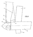
- Figure 6 shows the embodiment of a complete wind turbine, with the tower (8), nacelle (9) and blade (3) and where the installation of these high-lift detachments is specifically shown on a wind turbine blade in which the safety distance of the different devices are graphically indicated: safety distance from the hub (5), safety distance from the nacelle (6) and safety distance from the tower (7), for a maximum chord length, so that a safety distance of around 300 mm from the nacelle, around 300 mm from the hub and around 400 mm from the tower is obtained.
Abstract
Description
- The aim of the present invention patent is a wind turbine blade with high-lift devices in the blade's root area, where there are two types of these elements: high-lift devices on the leading edge area and on the trailing edge area, so that said blade is aerodynamically optimized in its whole geometry to increase the wind turbine's energy production.
- Traditional wind turbine blades are joined to the hub in a cylindrical area known as the root, with a characteristic length of usually several meters. For most wind turbines, the function of this area is typically structural and does not significantly contribute to the wind turbine's production, as it is not aerodynamically optimized.
- In the current state of the art, detachable elements in the root area, are described to improve the blade's performance. However, they are characterized by having a sharp trailing edge and a very large chord length on the joint with the root.
- Thus for example, we have document
WO 2007/131937 that describes a blade for a wind-power generator with a detachable element on the trailing edge detachable from the blade itself. - To solve the above mentioned problem mentioned, the wind turbine blade with a high-lift device is presented, object of the present patent of invention. Said high-lift devices are of two different types, according to their position and use in the blade:
- (i) High-lift device of the wind turbine trailing edge area;
- (ii) High-lift device of the wind turbine leading edge area;
- The high-lift device of the trailing edge is a fixed part, and not mobile like in other aerodynamic trailing edge devices related in the state of the art. The trailing edge of this element is thicker than known trailing edges, obtaining a bigger lift coefficient, which at the same time allows to make the detachable element with less total length (less chord). In other words, a shorter length or chord is obtained for the same lift, with greater trailing edge relative thickness. The device also allows to make a blade with less torsion, owing to having a greater stall angle in losses at high angles of attack. This high-lift device can be part of a one-piece blade and not only as an additional or detachable element.
- The leading edge's high-lift device is selected amongst:
- (i) a first leading edge high-lift device, slightly curved adapted to the blade root without inflection points on its outer surface;
- (ii) a second leading edge high-lift device, with a smaller contact surface with the blade root and an inflection point on its outer surface, on the bottom, improving its operating performance;
- (iii) a third leading edge high-lift device, with a pronounced outer profile, without inflection points on the surface and a contact area with the bottom root of the first and second devices' inflection points;
- (iv) a fourth leading edge high-lift device, with a minimum contact area with the root, which at the same time creates a very pronounced inflection point on the outer surface of this fourth element, increasing the maximum lift coefficient;
- The following technical advantages are obtained with the combined use of the two configurations (trailing edge and leading edge):
- The wind turbine produces more energy, on improving the blades' aerodynamic coefficient.
- Improved performance is obtained at lower ambient wind speeds, as the wind incidence angle has been improved.
- The already installed blades can be used, and their production and transport is also improved and made easier.
- A brief description of a series of illustrations is provided below in order to better understand the invention. These illustrations are expressly listed with an embodiment of the present invention and are presented as an illustrative, but not restrictive, example of the same.
-
Figure 1 is a ground plan of a wind turbine blade with incorporated high-lift devices, as described in the present invention. -
Figure 2 is a transversal section of the wind turbine blade with the first high-lift device of the leading edge installed. -
Figure 3 is a transversal section of the wind turbine blade with the second high-lift device of the leading edge installed. -
Figure 4 is a transversal section of the wind turbine blade with the third high-lift device of the leading edge installed. -
Figure 5 is a transversal section of the wind turbine blade with the fourth high-lift device of the leading edge installed. -
Figure 6 is a profile view of a wind turbine with installed high-lift devices, according to the present invention. - As can be observed in the attached figures, the wind turbine blade with high-lift devices comprises, at least, a trailing edge high-lift device (1) with a blunt end and chord (C) length of 5% to 30% less than a conventional profile for the same lift coefficient; and as the joint area radius is related to the blade's (3) root (4) radius, and to the thickness of this trailing edge high-lift device (1).
- The first trailing edge high-lift device (1) can be detachable or integrated in a one-piece blade.
- The leading edge's high-lift device (2) is selected amongst:
- (i) a first leading edge high-lift device (20), slightly curved adapted to the blade (3) root (4) without inflection points on its outer surface;
- (ii) a second leading edge high-lift device (21), with a smaller contact surface with the blade (3) root (4) and an inflection point on its outer surface, on the bottom;
- (iii) a third leading edge high-lift device (22), with a pronounced outer profile, that maintains the clearance between it and the root so than a certain amount of air flow can pass between the intrados and extrados of the profile to energize the profile extrados' boundary layer and improve aerodynamic performance, where this third element (22) can also be mobile (rotary with respect to the center of the cylinder and known in aerodynamics as "slot") so that it is better adapted to operating conditions set by the ambient flow with the modification of CL and αstall.
- (iv) a fourth leading edge high-lift device (23), with a minimum contact area with the root (4), which at the same time favours a very pronounced inflection point in the outer surface of this fourth element (23), where, additionally, this fourth leading edge high-lift device (23) or slot, can be mobile (rotary, idem), so that the CL and αSTALL ratio is optimized.
- In the design of high-lift devices coupled to the wind turbine blade, both on the leading edge and trailing edge, as well as taking into account optimising the ration between CL lift coefficient and the αSTALL angle of attack, a safety distance between the geometrical limits of the detachments and the machine itself should be taken into account.
-
Figure 6 shows the embodiment of a complete wind turbine, with the tower (8), nacelle (9) and blade (3) and where the installation of these high-lift detachments is specifically shown on a wind turbine blade in which the safety distance of the different devices are graphically indicated: safety distance from the hub (5), safety distance from the nacelle (6) and safety distance from the tower (7), for a maximum chord length, so that a safety distance of around 300 mm from the nacelle, around 300 mm from the hub and around 400 mm from the tower is obtained.
Claims (4)
- Wind turbine blade with high-lift devices characterized by having at least- a leading edge high-lift device (2), integrated in the blade root, with relative movement between the leading edge's detachable element and the blade root- a trailing edge high-lift device (1) integrated in the blade root giving continuity to the blade surface in a chord (C) length and with a blunt edge.
- Wind turbine blade with high-lift devices from claim 1 characterized by the leading edge high-lift device (2) being one selected amongst:(i) a first leading edge high-lift device (20), slightly curved adapted to the blade (3) root (4) without inflection points on its outer surface;(ii) a second leading edge high-lift device (21), with a smaller contact surface with the blade (3) root (4) and an inflection point on its outer surface, on the bottom;(iii) a third leading edge high-lift device (22), with a pronounced outer profile, without inflection points on the surface and a contact area with the bottom root of the of the first (20) and second element's (21) inflection points;(iv) a fourth leading edge high-lift device (23), with a minimum contact area with the root (4), which at the same time creates a very pronounced inflection point on the outer surface of this fourth element (23).
- Wind turbine blade with high-lift devices, according to claim 1, characterized by it including, at least, a trailing edge high-lift device (1) with a blunt end and chord (C) length of 5% to 30% less than a conventional profile for the same lift coefficient;
- Wind turbine blade with high-lift devices from claim 1 characterized by the joint area radius being related with the root (4) of the blade (3), and the thickness of this trailing edge high-lift device (1).
Applications Claiming Priority (2)
| Application Number | Priority Date | Filing Date | Title |
|---|---|---|---|
| ES200801632A ES2330500B1 (en) | 2008-05-30 | 2008-05-30 | AEROGENERATOR SHOVEL WITH HYPERSUSTENTING ELEMENTS. |
| PCT/ES2009/070191 WO2009144356A1 (en) | 2008-05-30 | 2009-05-28 | Wind generator blade with hyper-supporting elements |
Publications (3)
| Publication Number | Publication Date |
|---|---|
| EP2292926A1 true EP2292926A1 (en) | 2011-03-09 |
| EP2292926A4 EP2292926A4 (en) | 2014-11-12 |
| EP2292926B1 EP2292926B1 (en) | 2018-10-24 |
Family
ID=41350356
Family Applications (1)
| Application Number | Title | Priority Date | Filing Date |
|---|---|---|---|
| EP09754010.8A Not-in-force EP2292926B1 (en) | 2008-05-30 | 2009-05-28 | Wind generator blade with hyper-supporting elements |
Country Status (6)
| Country | Link |
|---|---|
| US (1) | US20110064582A1 (en) |
| EP (1) | EP2292926B1 (en) |
| CN (1) | CN102046963A (en) |
| DK (1) | DK2292926T3 (en) |
| ES (2) | ES2330500B1 (en) |
| WO (1) | WO2009144356A1 (en) |
Cited By (9)
| Publication number | Priority date | Publication date | Assignee | Title |
|---|---|---|---|---|
| EP2228534A1 (en) * | 2007-11-28 | 2010-09-15 | Gamesa Innovation & Technology, S.L. | Aerodynamic profile for the root of a wind turbine blade having a double leading edge |
| EP2527642A2 (en) | 2011-05-26 | 2012-11-28 | L&L Rotorservice GmbH | Rotor blade of a wind turbine |
| WO2013092852A1 (en) | 2011-12-22 | 2013-06-27 | Lm Wind Power A/S | Wind turbine blade assembled from inboard and outboard blade parts |
| EP2784301A1 (en) * | 2013-03-28 | 2014-10-01 | General Electric Company | Rotor blade assembly for wind turbine having load reduction features |
| DK177920B1 (en) * | 2011-09-27 | 2015-01-05 | Gen Electric | Wind turbine blade unit |
| DK178360B1 (en) * | 2011-05-20 | 2016-01-11 | Gen Electric | Root flap for rotor blade in wind turbine |
| EP2998572A1 (en) | 2014-09-22 | 2016-03-23 | Best Blades GmbH | Wind energy plant rotor blade |
| US10507902B2 (en) | 2015-04-21 | 2019-12-17 | General Electric Company | Wind turbine dome and method of assembly |
| EP2985452B1 (en) * | 2014-08-12 | 2020-07-15 | Senvion Deutschland GmbH | Rotor blade extension body and wind energy plant |
Families Citing this family (7)
| Publication number | Priority date | Publication date | Assignee | Title |
|---|---|---|---|---|
| EP2031241A1 (en) | 2007-08-29 | 2009-03-04 | Lm Glasfiber A/S | Blade for a rotor of a wind turbine provided with barrier generating means |
| ES2330500B1 (en) | 2008-05-30 | 2010-09-13 | GAMESA INNOVATION & TECHNOLOGY, S.L. UNIPERSONAL | AEROGENERATOR SHOVEL WITH HYPERSUSTENTING ELEMENTS. |
| US8936435B2 (en) | 2011-12-16 | 2015-01-20 | General Electric Company | System and method for root loss reduction in wind turbine blades |
| ES2393329B2 (en) * | 2012-10-22 | 2013-05-06 | Universidad De La Rioja | Hyper-hypo support device for the root region of a wind turbine blade |
| BR112017000756B1 (en) * | 2014-07-14 | 2022-08-02 | Lm Wp Patent Holding A/S | PROFILE WEDGE FOR CONNECTING AN AEROSHELD EXTENSION PIECE |
| DE102015116634A1 (en) * | 2015-10-01 | 2017-04-06 | Wobben Properties Gmbh | Wind turbine rotor blade and wind turbine |
| DE102016123412A1 (en) * | 2016-12-05 | 2018-06-07 | Wobben Properties Gmbh | Rotor blade for a wind turbine and wind turbine |
Citations (5)
| Publication number | Priority date | Publication date | Assignee | Title |
|---|---|---|---|---|
| US2541565A (en) | 1946-03-30 | 1951-02-13 | Curtiss Wright Corp | Airfoil and slat assembly |
| US4840540A (en) | 1987-06-27 | 1989-06-20 | Deutsche Forchungs- Und Versuchsanstalt Fur Luft- Und Raumfahrt E.V. | Propeller whose blades are provided with slats |
| WO2005105570A1 (en) | 2003-10-14 | 2005-11-10 | Sikorsky Aircraft Corporation | Leading edge slat airfoil for multi-element rotor blade airfoils |
| WO2009026927A2 (en) | 2007-08-29 | 2009-03-05 | Lm Glasfiber A/S | Blade for a rotor of a wind turbine provided with barrier generating means |
| WO2009144356A1 (en) | 2008-05-30 | 2009-12-03 | Gamesa Innovation & Technology, S.L. | Wind generator blade with hyper-supporting elements |
Family Cites Families (19)
| Publication number | Priority date | Publication date | Assignee | Title |
|---|---|---|---|---|
| US3128966A (en) * | 1964-04-14 | Alvarez-calderon | ||
| US2026482A (en) * | 1932-09-09 | 1935-12-31 | Mattioli Gian Domenico | Control for aerofoils, etc. |
| US2135887A (en) * | 1935-06-07 | 1938-11-08 | Fairey Charles Richard | Blade for airscrews and the like |
| US2399828A (en) * | 1941-10-29 | 1946-05-07 | Roche Jean Alfred | Propeller |
| US2622686A (en) * | 1942-07-21 | 1952-12-23 | Chevreau Rene Louis Pier Marie | Wind motor |
| US2729297A (en) * | 1951-08-01 | 1956-01-03 | Smith Corp A O | Propeller cuff |
| CA1169778A (en) * | 1981-11-04 | 1984-06-26 | Witold Brzozowski | Slat for wind energy convertor |
| US4702441A (en) * | 1984-12-31 | 1987-10-27 | The Boeing Company | Aircraft wing stall control device and method |
| US4830574A (en) * | 1988-02-29 | 1989-05-16 | United Technologies Corporation | Airfoiled blade |
| GB2227286A (en) * | 1989-01-17 | 1990-07-25 | Howden Wind Turbines Limited | Control of a wind turbine and adjustable blade therefor |
| NL1015558C2 (en) * | 2000-06-28 | 2002-01-08 | Stichting En Onderzoek Ct Nede | Blade of a wind turbine. |
| US7059833B2 (en) * | 2001-11-26 | 2006-06-13 | Bonus Energy A/S | Method for improvement of the efficiency of a wind turbine rotor |
| DE03815629T1 (en) * | 2003-01-23 | 2006-04-13 | Bell Helicopter Textron, Inc., Fort Worth | PROPELLER LEAF WITH GUIDE EDGE NUT |
| CA2425447C (en) * | 2003-04-17 | 2006-03-14 | Michel J. L. Auclair | Wind turbine blade unit |
| DK176317B1 (en) * | 2005-10-17 | 2007-07-30 | Lm Glasfiber As | Blade for a rotor on a wind turbine |
| CN101321949B (en) * | 2005-12-05 | 2013-03-13 | Lm玻璃纤维制品有限公司 | Blade for a wind turbine rotor |
| BRPI0600613B1 (en) * | 2006-03-14 | 2015-08-11 | Tecsis Tecnologia E Sist S Avançados S A | Multi-element blade with aerodynamic profiles |
| DE102006022279B4 (en) * | 2006-05-11 | 2016-05-12 | Aloys Wobben | Rotor blade for a wind energy plant |
| DK2078852T4 (en) * | 2008-01-11 | 2022-07-04 | Siemens Gamesa Renewable Energy As | Rotor blade for a wind turbine |
-
2008
- 2008-05-30 ES ES200801632A patent/ES2330500B1/en not_active Expired - Fee Related
-
2009
- 2009-05-28 EP EP09754010.8A patent/EP2292926B1/en not_active Not-in-force
- 2009-05-28 US US12/994,290 patent/US20110064582A1/en not_active Abandoned
- 2009-05-28 ES ES09754010T patent/ES2700882T3/en active Active
- 2009-05-28 CN CN2009801201077A patent/CN102046963A/en active Pending
- 2009-05-28 WO PCT/ES2009/070191 patent/WO2009144356A1/en active Application Filing
- 2009-05-28 DK DK09754010.8T patent/DK2292926T3/en active
Patent Citations (6)
| Publication number | Priority date | Publication date | Assignee | Title |
|---|---|---|---|---|
| US2541565A (en) | 1946-03-30 | 1951-02-13 | Curtiss Wright Corp | Airfoil and slat assembly |
| US4840540A (en) | 1987-06-27 | 1989-06-20 | Deutsche Forchungs- Und Versuchsanstalt Fur Luft- Und Raumfahrt E.V. | Propeller whose blades are provided with slats |
| WO2005105570A1 (en) | 2003-10-14 | 2005-11-10 | Sikorsky Aircraft Corporation | Leading edge slat airfoil for multi-element rotor blade airfoils |
| WO2009026927A2 (en) | 2007-08-29 | 2009-03-05 | Lm Glasfiber A/S | Blade for a rotor of a wind turbine provided with barrier generating means |
| EP2201243A2 (en) | 2007-08-29 | 2010-06-30 | Lm Glasfiber A/S | Blade for a rotor of a wind turbine provided with barrier generating means |
| WO2009144356A1 (en) | 2008-05-30 | 2009-12-03 | Gamesa Innovation & Technology, S.L. | Wind generator blade with hyper-supporting elements |
Non-Patent Citations (1)
| Title |
|---|
| See also references of WO2009144356A1 |
Cited By (12)
| Publication number | Priority date | Publication date | Assignee | Title |
|---|---|---|---|---|
| EP2228534A1 (en) * | 2007-11-28 | 2010-09-15 | Gamesa Innovation & Technology, S.L. | Aerodynamic profile for the root of a wind turbine blade having a double leading edge |
| EP2228534A4 (en) * | 2007-11-28 | 2013-07-31 | Gamesa Innovation & Tech Sl | Aerodynamic profile for the root of a wind turbine blade having a double leading edge |
| DK178360B1 (en) * | 2011-05-20 | 2016-01-11 | Gen Electric | Root flap for rotor blade in wind turbine |
| EP2527642A2 (en) | 2011-05-26 | 2012-11-28 | L&L Rotorservice GmbH | Rotor blade of a wind turbine |
| DK177920B1 (en) * | 2011-09-27 | 2015-01-05 | Gen Electric | Wind turbine blade unit |
| WO2013092852A1 (en) | 2011-12-22 | 2013-06-27 | Lm Wind Power A/S | Wind turbine blade assembled from inboard and outboard blade parts |
| EP2784301A1 (en) * | 2013-03-28 | 2014-10-01 | General Electric Company | Rotor blade assembly for wind turbine having load reduction features |
| US9670900B2 (en) | 2013-03-28 | 2017-06-06 | General Electric Company | Rotor blade assembly for wind turbine having load reduction features |
| EP2985452B1 (en) * | 2014-08-12 | 2020-07-15 | Senvion Deutschland GmbH | Rotor blade extension body and wind energy plant |
| EP2998572A1 (en) | 2014-09-22 | 2016-03-23 | Best Blades GmbH | Wind energy plant rotor blade |
| WO2016045656A1 (en) | 2014-09-22 | 2016-03-31 | Best Blades Gmbh | Wind turbine rotor blade |
| US10507902B2 (en) | 2015-04-21 | 2019-12-17 | General Electric Company | Wind turbine dome and method of assembly |
Also Published As
| Publication number | Publication date |
|---|---|
| EP2292926A4 (en) | 2014-11-12 |
| CN102046963A (en) | 2011-05-04 |
| ES2330500B1 (en) | 2010-09-13 |
| ES2330500A1 (en) | 2009-12-10 |
| ES2700882T3 (en) | 2019-02-19 |
| EP2292926B1 (en) | 2018-10-24 |
| DK2292926T3 (en) | 2019-01-28 |
| US20110064582A1 (en) | 2011-03-17 |
| WO2009144356A1 (en) | 2009-12-03 |
Similar Documents
| Publication | Publication Date | Title |
|---|---|---|
| EP2292926B1 (en) | Wind generator blade with hyper-supporting elements | |
| US8944775B2 (en) | Wind turbine blade having a spoiler with effective separation of airflow | |
| CN109416017B (en) | Rotor blade with serrated trailing edge | |
| EP2286084B1 (en) | A wind turbine blade with an auxiliary airfoil | |
| EP2604856B1 (en) | Wind turbine blade, wind power generation device provided with same, and design method for wind turbine blade | |
| EP2368034B1 (en) | Wind turbine blade having a flow guiding device with optimised height | |
| EP2713044B1 (en) | Wind turbine rotor blade | |
| EP3722594B1 (en) | Wind turbine blade with flow blocking means and vortex generators | |
| DK178360B1 (en) | Root flap for rotor blade in wind turbine | |
| EP1944505A1 (en) | Wind turbine rotor blade with vortex generators | |
| US10400744B2 (en) | Wind turbine blade with noise reducing micro boundary layer energizers | |
| CN105715449B (en) | Rotor blade with vortex generators and wind turbine | |
| EP2682602B1 (en) | Wind turbine blade and wind-powered electricity generator provided with same | |
| EP2078852B1 (en) | Wind turbine rotor blade | |
| US8936435B2 (en) | System and method for root loss reduction in wind turbine blades | |
| EP3453872B1 (en) | Methods for mitigating noise during high wind speed conditions of wind turbines |
Legal Events
| Date | Code | Title | Description |
|---|---|---|---|
| PUAI | Public reference made under article 153(3) epc to a published international application that has entered the european phase |
Free format text: ORIGINAL CODE: 0009012 |
|
| 17P | Request for examination filed |
Effective date: 20101123 |
|
| AK | Designated contracting states |
Kind code of ref document: A1 Designated state(s): AT BE BG CH CY CZ DE DK EE ES FI FR GB GR HR HU IE IS IT LI LT LU LV MC MK MT NL NO PL PT RO SE SI SK TR |
|
| AX | Request for extension of the european patent |
Extension state: AL BA RS |
|
| DAX | Request for extension of the european patent (deleted) | ||
| TPAC | Observations filed by third parties |
Free format text: ORIGINAL CODE: EPIDOSNTIPA |
|
| A4 | Supplementary search report drawn up and despatched |
Effective date: 20141010 |
|
| RIC1 | Information provided on ipc code assigned before grant |
Ipc: F03D 1/06 20060101AFI20141006BHEP |
|
| GRAP | Despatch of communication of intention to grant a patent |
Free format text: ORIGINAL CODE: EPIDOSNIGR1 |
|
| STAA | Information on the status of an ep patent application or granted ep patent |
Free format text: STATUS: GRANT OF PATENT IS INTENDED |
|
| INTG | Intention to grant announced |
Effective date: 20180509 |
|
| GRAS | Grant fee paid |
Free format text: ORIGINAL CODE: EPIDOSNIGR3 |
|
| GRAA | (expected) grant |
Free format text: ORIGINAL CODE: 0009210 |
|
| STAA | Information on the status of an ep patent application or granted ep patent |
Free format text: STATUS: THE PATENT HAS BEEN GRANTED |
|
| AK | Designated contracting states |
Kind code of ref document: B1 Designated state(s): AT BE BG CH CY CZ DE DK EE ES FI FR GB GR HR HU IE IS IT LI LT LU LV MC MK MT NL NO PL PT RO SE SI SK TR |
|
| REG | Reference to a national code |
Ref country code: GB Ref legal event code: FG4D |
|
| REG | Reference to a national code |
Ref country code: CH Ref legal event code: EP |
|
| REG | Reference to a national code |
Ref country code: IE Ref legal event code: FG4D |
|
| REG | Reference to a national code |
Ref country code: DE Ref legal event code: R096 Ref document number: 602009055255 Country of ref document: DE Ref country code: AT Ref legal event code: REF Ref document number: 1056962 Country of ref document: AT Kind code of ref document: T Effective date: 20181115 |
|
| REG | Reference to a national code |
Ref country code: DK Ref legal event code: T3 Effective date: 20190123 |
|
| REG | Reference to a national code |
Ref country code: ES Ref legal event code: FG2A Ref document number: 2700882 Country of ref document: ES Kind code of ref document: T3 Effective date: 20190219 |
|
| REG | Reference to a national code |
Ref country code: NL Ref legal event code: MP Effective date: 20181024 |
|
| REG | Reference to a national code |
Ref country code: LT Ref legal event code: MG4D |
|
| REG | Reference to a national code |
Ref country code: AT Ref legal event code: MK05 Ref document number: 1056962 Country of ref document: AT Kind code of ref document: T Effective date: 20181024 |
|
| PG25 | Lapsed in a contracting state [announced via postgrant information from national office to epo] |
Ref country code: NL Free format text: LAPSE BECAUSE OF FAILURE TO SUBMIT A TRANSLATION OF THE DESCRIPTION OR TO PAY THE FEE WITHIN THE PRESCRIBED TIME-LIMIT Effective date: 20181024 |
|
| RAP2 | Party data changed (patent owner data changed or rights of a patent transferred) |
Owner name: SIEMENS GAMESA RENEWABLE ENERGY INNOVATION & TECHN |
|
| PG25 | Lapsed in a contracting state [announced via postgrant information from national office to epo] |
Ref country code: FI Free format text: LAPSE BECAUSE OF FAILURE TO SUBMIT A TRANSLATION OF THE DESCRIPTION OR TO PAY THE FEE WITHIN THE PRESCRIBED TIME-LIMIT Effective date: 20181024 Ref country code: BG Free format text: LAPSE BECAUSE OF FAILURE TO SUBMIT A TRANSLATION OF THE DESCRIPTION OR TO PAY THE FEE WITHIN THE PRESCRIBED TIME-LIMIT Effective date: 20190124 Ref country code: IS Free format text: LAPSE BECAUSE OF FAILURE TO SUBMIT A TRANSLATION OF THE DESCRIPTION OR TO PAY THE FEE WITHIN THE PRESCRIBED TIME-LIMIT Effective date: 20190224 Ref country code: LT Free format text: LAPSE BECAUSE OF FAILURE TO SUBMIT A TRANSLATION OF THE DESCRIPTION OR TO PAY THE FEE WITHIN THE PRESCRIBED TIME-LIMIT Effective date: 20181024 Ref country code: NO Free format text: LAPSE BECAUSE OF FAILURE TO SUBMIT A TRANSLATION OF THE DESCRIPTION OR TO PAY THE FEE WITHIN THE PRESCRIBED TIME-LIMIT Effective date: 20190124 Ref country code: AT Free format text: LAPSE BECAUSE OF FAILURE TO SUBMIT A TRANSLATION OF THE DESCRIPTION OR TO PAY THE FEE WITHIN THE PRESCRIBED TIME-LIMIT Effective date: 20181024 Ref country code: HR Free format text: LAPSE BECAUSE OF FAILURE TO SUBMIT A TRANSLATION OF THE DESCRIPTION OR TO PAY THE FEE WITHIN THE PRESCRIBED TIME-LIMIT Effective date: 20181024 Ref country code: PL Free format text: LAPSE BECAUSE OF FAILURE TO SUBMIT A TRANSLATION OF THE DESCRIPTION OR TO PAY THE FEE WITHIN THE PRESCRIBED TIME-LIMIT Effective date: 20181024 Ref country code: LV Free format text: LAPSE BECAUSE OF FAILURE TO SUBMIT A TRANSLATION OF THE DESCRIPTION OR TO PAY THE FEE WITHIN THE PRESCRIBED TIME-LIMIT Effective date: 20181024 |
|
| PG25 | Lapsed in a contracting state [announced via postgrant information from national office to epo] |
Ref country code: PT Free format text: LAPSE BECAUSE OF FAILURE TO SUBMIT A TRANSLATION OF THE DESCRIPTION OR TO PAY THE FEE WITHIN THE PRESCRIBED TIME-LIMIT Effective date: 20190224 Ref country code: SE Free format text: LAPSE BECAUSE OF FAILURE TO SUBMIT A TRANSLATION OF THE DESCRIPTION OR TO PAY THE FEE WITHIN THE PRESCRIBED TIME-LIMIT Effective date: 20181024 Ref country code: GR Free format text: LAPSE BECAUSE OF FAILURE TO SUBMIT A TRANSLATION OF THE DESCRIPTION OR TO PAY THE FEE WITHIN THE PRESCRIBED TIME-LIMIT Effective date: 20190125 |
|
| REG | Reference to a national code |
Ref country code: DE Ref legal event code: R097 Ref document number: 602009055255 Country of ref document: DE |
|
| PG25 | Lapsed in a contracting state [announced via postgrant information from national office to epo] |
Ref country code: IT Free format text: LAPSE BECAUSE OF FAILURE TO SUBMIT A TRANSLATION OF THE DESCRIPTION OR TO PAY THE FEE WITHIN THE PRESCRIBED TIME-LIMIT Effective date: 20181024 Ref country code: CZ Free format text: LAPSE BECAUSE OF FAILURE TO SUBMIT A TRANSLATION OF THE DESCRIPTION OR TO PAY THE FEE WITHIN THE PRESCRIBED TIME-LIMIT Effective date: 20181024 |
|
| PG25 | Lapsed in a contracting state [announced via postgrant information from national office to epo] |
Ref country code: EE Free format text: LAPSE BECAUSE OF FAILURE TO SUBMIT A TRANSLATION OF THE DESCRIPTION OR TO PAY THE FEE WITHIN THE PRESCRIBED TIME-LIMIT Effective date: 20181024 Ref country code: SK Free format text: LAPSE BECAUSE OF FAILURE TO SUBMIT A TRANSLATION OF THE DESCRIPTION OR TO PAY THE FEE WITHIN THE PRESCRIBED TIME-LIMIT Effective date: 20181024 Ref country code: RO Free format text: LAPSE BECAUSE OF FAILURE TO SUBMIT A TRANSLATION OF THE DESCRIPTION OR TO PAY THE FEE WITHIN THE PRESCRIBED TIME-LIMIT Effective date: 20181024 |
|
| PLBE | No opposition filed within time limit |
Free format text: ORIGINAL CODE: 0009261 |
|
| STAA | Information on the status of an ep patent application or granted ep patent |
Free format text: STATUS: NO OPPOSITION FILED WITHIN TIME LIMIT |
|
| 26N | No opposition filed |
Effective date: 20190725 |
|
| PG25 | Lapsed in a contracting state [announced via postgrant information from national office to epo] |
Ref country code: SI Free format text: LAPSE BECAUSE OF FAILURE TO SUBMIT A TRANSLATION OF THE DESCRIPTION OR TO PAY THE FEE WITHIN THE PRESCRIBED TIME-LIMIT Effective date: 20181024 |
|
| REG | Reference to a national code |
Ref country code: CH Ref legal event code: PL |
|
| PG25 | Lapsed in a contracting state [announced via postgrant information from national office to epo] |
Ref country code: CH Free format text: LAPSE BECAUSE OF NON-PAYMENT OF DUE FEES Effective date: 20190531 Ref country code: LI Free format text: LAPSE BECAUSE OF NON-PAYMENT OF DUE FEES Effective date: 20190531 Ref country code: MC Free format text: LAPSE BECAUSE OF FAILURE TO SUBMIT A TRANSLATION OF THE DESCRIPTION OR TO PAY THE FEE WITHIN THE PRESCRIBED TIME-LIMIT Effective date: 20181024 |
|
| REG | Reference to a national code |
Ref country code: BE Ref legal event code: MM Effective date: 20190531 |
|
| PG25 | Lapsed in a contracting state [announced via postgrant information from national office to epo] |
Ref country code: LU Free format text: LAPSE BECAUSE OF NON-PAYMENT OF DUE FEES Effective date: 20190528 |
|
| PG25 | Lapsed in a contracting state [announced via postgrant information from national office to epo] |
Ref country code: TR Free format text: LAPSE BECAUSE OF FAILURE TO SUBMIT A TRANSLATION OF THE DESCRIPTION OR TO PAY THE FEE WITHIN THE PRESCRIBED TIME-LIMIT Effective date: 20181024 |
|
| PG25 | Lapsed in a contracting state [announced via postgrant information from national office to epo] |
Ref country code: IE Free format text: LAPSE BECAUSE OF NON-PAYMENT OF DUE FEES Effective date: 20190528 |
|
| PG25 | Lapsed in a contracting state [announced via postgrant information from national office to epo] |
Ref country code: BE Free format text: LAPSE BECAUSE OF NON-PAYMENT OF DUE FEES Effective date: 20190531 |
|
| PG25 | Lapsed in a contracting state [announced via postgrant information from national office to epo] |
Ref country code: FR Free format text: LAPSE BECAUSE OF NON-PAYMENT OF DUE FEES Effective date: 20190531 |
|
| PGFP | Annual fee paid to national office [announced via postgrant information from national office to epo] |
Ref country code: ES Payment date: 20200827 Year of fee payment: 12 Ref country code: DE Payment date: 20200720 Year of fee payment: 12 |
|
| PG25 | Lapsed in a contracting state [announced via postgrant information from national office to epo] |
Ref country code: CY Free format text: LAPSE BECAUSE OF FAILURE TO SUBMIT A TRANSLATION OF THE DESCRIPTION OR TO PAY THE FEE WITHIN THE PRESCRIBED TIME-LIMIT Effective date: 20181024 |
|
| PG25 | Lapsed in a contracting state [announced via postgrant information from national office to epo] |
Ref country code: HU Free format text: LAPSE BECAUSE OF FAILURE TO SUBMIT A TRANSLATION OF THE DESCRIPTION OR TO PAY THE FEE WITHIN THE PRESCRIBED TIME-LIMIT; INVALID AB INITIO Effective date: 20090528 Ref country code: MT Free format text: LAPSE BECAUSE OF FAILURE TO SUBMIT A TRANSLATION OF THE DESCRIPTION OR TO PAY THE FEE WITHIN THE PRESCRIBED TIME-LIMIT Effective date: 20181024 |
|
| PGFP | Annual fee paid to national office [announced via postgrant information from national office to epo] |
Ref country code: GB Payment date: 20210602 Year of fee payment: 13 Ref country code: DK Payment date: 20210521 Year of fee payment: 13 |
|
| REG | Reference to a national code |
Ref country code: DE Ref legal event code: R119 Ref document number: 602009055255 Country of ref document: DE |
|
| PG25 | Lapsed in a contracting state [announced via postgrant information from national office to epo] |
Ref country code: DE Free format text: LAPSE BECAUSE OF NON-PAYMENT OF DUE FEES Effective date: 20211201 |
|
| PG25 | Lapsed in a contracting state [announced via postgrant information from national office to epo] |
Ref country code: MK Free format text: LAPSE BECAUSE OF FAILURE TO SUBMIT A TRANSLATION OF THE DESCRIPTION OR TO PAY THE FEE WITHIN THE PRESCRIBED TIME-LIMIT Effective date: 20181024 |
|
| REG | Reference to a national code |
Ref country code: ES Ref legal event code: FD2A Effective date: 20220826 |
|
| PG25 | Lapsed in a contracting state [announced via postgrant information from national office to epo] |
Ref country code: ES Free format text: LAPSE BECAUSE OF NON-PAYMENT OF DUE FEES Effective date: 20210529 |
|
| REG | Reference to a national code |
Ref country code: DK Ref legal event code: EBP Effective date: 20220531 |
|
| GBPC | Gb: european patent ceased through non-payment of renewal fee |
Effective date: 20220528 |
|
| PG25 | Lapsed in a contracting state [announced via postgrant information from national office to epo] |
Ref country code: DK Free format text: LAPSE BECAUSE OF NON-PAYMENT OF DUE FEES Effective date: 20220531 |
|
| PG25 | Lapsed in a contracting state [announced via postgrant information from national office to epo] |
Ref country code: GB Free format text: LAPSE BECAUSE OF NON-PAYMENT OF DUE FEES Effective date: 20220528 |