EP2275672A2 - Boundary layer fins for wind turbine blade - Google Patents
Boundary layer fins for wind turbine blade Download PDFInfo
- Publication number
- EP2275672A2 EP2275672A2 EP10163335A EP10163335A EP2275672A2 EP 2275672 A2 EP2275672 A2 EP 2275672A2 EP 10163335 A EP10163335 A EP 10163335A EP 10163335 A EP10163335 A EP 10163335A EP 2275672 A2 EP2275672 A2 EP 2275672A2
- Authority
- EP
- European Patent Office
- Prior art keywords
- boundary layer
- blade
- wind turbine
- fins
- turbine blade
- Prior art date
- Legal status (The legal status is an assumption and is not a legal conclusion. Google has not performed a legal analysis and makes no representation as to the accuracy of the status listed.)
- Granted
Links
- 238000000926 separation method Methods 0.000 claims abstract description 15
- 230000003247 decreasing effect Effects 0.000 description 4
- 238000005516 engineering process Methods 0.000 description 3
- 230000002411 adverse Effects 0.000 description 2
- 238000013459 approach Methods 0.000 description 2
- 239000012530 fluid Substances 0.000 description 2
- 241000209140 Triticum Species 0.000 description 1
- 235000021307 Triticum Nutrition 0.000 description 1
- 230000000052 comparative effect Effects 0.000 description 1
- 238000010276 construction Methods 0.000 description 1
- 230000005611 electricity Effects 0.000 description 1
- 238000011084 recovery Methods 0.000 description 1
- 238000004088 simulation Methods 0.000 description 1
- XLYOFNOQVPJJNP-UHFFFAOYSA-N water Substances O XLYOFNOQVPJJNP-UHFFFAOYSA-N 0.000 description 1
Images


Classifications
-
- F—MECHANICAL ENGINEERING; LIGHTING; HEATING; WEAPONS; BLASTING
- F03—MACHINES OR ENGINES FOR LIQUIDS; WIND, SPRING, OR WEIGHT MOTORS; PRODUCING MECHANICAL POWER OR A REACTIVE PROPULSIVE THRUST, NOT OTHERWISE PROVIDED FOR
- F03D—WIND MOTORS
- F03D1/00—Wind motors with rotation axis substantially parallel to the air flow entering the rotor
- F03D1/06—Rotors
- F03D1/0608—Rotors characterised by their aerodynamic shape
- F03D1/0633—Rotors characterised by their aerodynamic shape of the blades
- F03D1/0641—Rotors characterised by their aerodynamic shape of the blades of the section profile of the blades, i.e. aerofoil profile
-
- F—MECHANICAL ENGINEERING; LIGHTING; HEATING; WEAPONS; BLASTING
- F03—MACHINES OR ENGINES FOR LIQUIDS; WIND, SPRING, OR WEIGHT MOTORS; PRODUCING MECHANICAL POWER OR A REACTIVE PROPULSIVE THRUST, NOT OTHERWISE PROVIDED FOR
- F03D—WIND MOTORS
- F03D1/00—Wind motors with rotation axis substantially parallel to the air flow entering the rotor
- F03D1/06—Rotors
- F03D1/065—Rotors characterised by their construction elements
-
- F—MECHANICAL ENGINEERING; LIGHTING; HEATING; WEAPONS; BLASTING
- F05—INDEXING SCHEMES RELATING TO ENGINES OR PUMPS IN VARIOUS SUBCLASSES OF CLASSES F01-F04
- F05B—INDEXING SCHEME RELATING TO WIND, SPRING, WEIGHT, INERTIA OR LIKE MOTORS, TO MACHINES OR ENGINES FOR LIQUIDS COVERED BY SUBCLASSES F03B, F03D AND F03G
- F05B2240/00—Components
- F05B2240/20—Rotors
- F05B2240/30—Characteristics of rotor blades, i.e. of any element transforming dynamic fluid energy to or from rotational energy and being attached to a rotor
- F05B2240/306—Surface measures
- F05B2240/3062—Vortex generators
-
- Y—GENERAL TAGGING OF NEW TECHNOLOGICAL DEVELOPMENTS; GENERAL TAGGING OF CROSS-SECTIONAL TECHNOLOGIES SPANNING OVER SEVERAL SECTIONS OF THE IPC; TECHNICAL SUBJECTS COVERED BY FORMER USPC CROSS-REFERENCE ART COLLECTIONS [XRACs] AND DIGESTS
- Y02—TECHNOLOGIES OR APPLICATIONS FOR MITIGATION OR ADAPTATION AGAINST CLIMATE CHANGE
- Y02E—REDUCTION OF GREENHOUSE GAS [GHG] EMISSIONS, RELATED TO ENERGY GENERATION, TRANSMISSION OR DISTRIBUTION
- Y02E10/00—Energy generation through renewable energy sources
- Y02E10/70—Wind energy
- Y02E10/72—Wind turbines with rotation axis in wind direction
Definitions
- the subject matter described here generally relates to wind turbine blades, and, more particularly, to boundary layer fins for a wind turbine blade.
- a wind turbine is a machine for converting the kinetic energy in wind into mechanical energy. If the mechanical energy is used directly by the machinery, such as to pump water or to grind wheat, then the wind turbine may be referred to as a windmill. Similarly, if the mechanical energy is converted to electricity, then the machine may also be referred to as a wind generator or wind power plant.
- Wind turbines are typically categorized according to the vertical or horizontal axis about which the blades rotate.
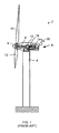
- One so-called horizontal-axis wind generator is schematically illustrated in FIG. 1 and available from General Electric Company.
- This particular configuration for a wind turbine 2 includes a tower 4 supporting a nacelle 6 enclosing a drive train 8.
- the blades 10 are arranged on a "spinner” or hub 9 to form a "rotor” at one end of the drive train 8 outside of the nacelle 6.
- the rotating blades 10 drive a gearbox 12 connected to an electrical generator 14 at the other end of the drive train 8 arranged inside the nacelle 6 along with a control system 16 that may receive input from an anemometer 18.
- the blades 10 generate lift and capture momentum from moving air that is then imparted to the rotor as the blades spin in the "rotor plane.”
- Each blade 10 is typically secured to the hub 9 at its "root” end, and then “spans" radially “outboard” to a free, “tip” end.
- the front, or “leading edge,” of the blade 10 connects the forward-most points of the blade that first contact the air.
- the rear, or “trailing edge,” of the blade 10 is where airflow that has been separated by the leading edge rejoins after passing over the suction and pressure surfaces of the blade.
- a “chord line” connects the leading and center of trailing edge of the blade.
- chord line The length of the chord line is simply the "chord.”
- the thickness of a blade 10 varies across the span, and the term “thickness” is typically used to describe the maximum distance between the low pressure suction surface and the high pressure surface on the opposite side of the blade for any particular chord line.
- a “boundary layer” is the zone of reduced velocity air that is immediately adjacent to the surface the moving blade 10.
- the thickness of the boundary layer is typically defined as the distance from the blade at which the flow velocity is 99% of the "freestream” velocity where the air is unaffected by the viscous or friction forces of the blade, but the potential flow is felt beyond the boundary layer.
- Flow separation occurs when the boundary layer travels far enough against an adverse pressure gradient that the flow velocity speed falls almost to zero. The fluid flow then becomes detached from flowing over the blade 10 and instead forms eddies and vortices.
- Boundary layer separation can increase drag on the blade 10, particularly the "pressure drag” which is caused by the pressure differential between the front and rear surfaces of the object as it travels through the fluid. Boundary layer separation may also lead to stall and vortex shedding that can causes noise and structural vibrations in the blade 10. For this reason much effort and research has gone into the design of aerodynamic surfaces which delay flow separation and keep the local flow attached to the blade 10 for as long as possible.
- International Patent Publication No. WO 2007/140771 and European Patent Application No. EP 1944505 discloses wind turbine blades with vortex generators. However, such vortex generators may reduce the energy that might otherwise be captured from the wind.
- a wind turbine blade including a plurality of boundary layer fins, aligned substantially parallel to a direction of flow over the blade, for reducing boundary layer separation from the blade.
- FIGs. are not necessarily drawn to scale, but use the same reference numerals to designate corresponding parts throughout each of the several views, and in which:
- boundary layer fins 22 may be laid out with respect to certain characteristics of the wind turbine blade including the span length of the blade, the corresponding chord on which the boundary layer fin is arranged, and/or the local boundary layer thickness where the boundary layer fin is to be arranged.
- the local boundary layer thickness is preferably calculated when the blade 20, or corresponding wind turbine 4, is operating without a boundary layer fin 22 and at its "rated rpm," which is typically around fifteen to twenty revolutions per minute with the blade 20 secured at its root end.
- the calculated local boundary layer thickness with the blade 20 operating at rated rpm will vary chordwise and spanwise over the blade from about 1 millimeter to about 202 millimeters.
- the boundary layer thickness is typically between about 6 millimeters and 52 millimeters. At roughly the same chord position for the outer 33% of the suction side of the span, the boundary layer thickness can range from about 6 millimeters to about 16 millimeters.
- the boundary layer fins 22 may be arranged along the entire span of the blade 20, or over only a portion of the span, such as where boundary layer separation is expected to occur.
- the boundary layer fins 22 may be arranged on the outer 10% to 100% of the span, the outer 25% to 95% of the span, or the outer 50% to 90% of the span of the blade 22.
- One or more boundary layer fins 22, or pairs of boundary layer fins, may also be provided at discrete locations along the span of the blade 22 where boundary layer separation is problematic or likely to become problematic.
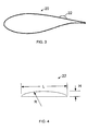
- the boundary layer fins 22 illustrated here extend along the chord on which the corresponding boundary layer fin is arranged. As illustrated in FIG. 3 , the leading edge of the boundary layer fin 22 may be displaced from the leading and trailing edges of the blade 20. For example, the leading edge of the boundary layer fin 22 may be displaced from the leading edge of the blade 20 between 10% and 95% of the chord, between 15% and 90% of the chord, or between 50% and 90% of the corresponding chord upon which the boundary layer fin is arranged.
- the leading and/or trailing edges of each of the boundary layer fins 22, or pairs of boundary layer fins 22 are not necessarily aligned with each other and the boundary layer fins 22 may also have different or the same lengths. For example, pairs, and/or other groups, of the boundary layer fins 22 may or may not have substantially the same position relative to the leading and trailing edges of the blade 20.
- the height "H,” length “L,” and/or radius of curvature “R” of the top surface of the boundary layer fins 22 may vary across the span of the blade 20.
- the height “H” may be between approximately 25% to 100%, or 50% to 75%, of the local boundary layer thickness at the corresponding boundary layer fin 22.
- the length “L” may be 2 to 40 times the height “H” or roughly 2 to 10 times the local boundary layer thickness, or about 1 to 4 times the local boundary thickness.
- the radius of curvature “R” may be substantially constant or vary over the length "L.” In various embodiments, the radius of curvature may be about 2 to 60 times the height "H,” or about 2 to 15 times the local boundary layer thickness. For example, the radius of curvature may vary from about 20 millimeters to 300 millimeters, or about 40 millimeters to about 150 millimeters, or about 60 millimeters to 100 millimeters.
- FIGs. 7 and 8 illustrate various other possible configurations for the top surface of some or all of the boundary layer fins 22.
- the thickness "t" of the boundary layer fins 22 may be approximately 10% to 100%, or 25% to 75%, of the height "H" of the corresponding boundary layer fin 22.
- the thickness of some or all of the boundary layer fins 22 may be substantially greater, so that a spanwise bump is formed over some or all of the blade 20.
- the distance "d" between two boundary layer fins in a pair or larger grouping may be about 2 to 32 times, or 4 to 16 times, the height "H," or about 2 to 8 times a local boundary layer thickness.
- the distance "D" between pairs or other groupings of boundary layer fins may also be about 2 to 32 times, or 4 to 16 times, the height "H," or about 2 to 8 times a local boundary layer thickness.
- the distance between individual boundary layer fins 22 and/or groups of boundary layer fins 22 may be substantially zero.
- FIGs. 9-11 show the results of a comparative flow simulation for a portion of the blade discussed above with and without the boundary layer fins shown 22 in FIG. 5 operating at an angle of attack of nine degrees.
- the leading edge of the boundary layer fins 22 is arranged at 60% of chord from the leading edge of the blade 22, the height “H” is 50% of the local boundary layer thickness, the length “L” is five times the local boundary layer thickness, the radius of curvature “R” of the top surface is 60 millimeters, the distance “d” between two boundary layer fins in a pair is 9.33 millimeters, and the distance “D” between two pairs of boundary layer fins is 16.56 millimeters.
- FIG. 9 shows pressure coefficient "C p " versus non-dimensional chord "x/c" where the plot 30 is for the baseline case without boundary layer fins and the plot 40 is for the boundary layer fins 22 described in the previous paragraph.
- FIG. 9 illustrates the improved pressure recovery provided by the boundary layer fins in the outboard region 50 near the trailing edge of the blade 20.
- FIG. 9 also illustrates the increased loading. in the leading edge region 52 of blade 20.
- FIG. 10 shows distance "N” in meters normal to the suction surface of the blade versus local flow velocity "V” in meters per second where the plot 30 is for the baseline case without boundary layer fins and the plot 40 is for the boundary layer fins 22 described above.
- Figure 10 illustrates the decreased boundary layer thickness in the region 54 approximately 0.02 to 0.06 meters from the suction surface of the blade 20.
- FIG.10 shows distance "N” in meters normal to the suction surface of the blade versus local turbulence kinetic energy "TKE" in meter-squared per second-squared where the plot 30 is for the baseline case without boundary layer fins and the plot 40 is for the boundary layer fins 22 described above.
- Figure 11 illustrates the decreased turbulence kinetic energy in the region 56 approximately 0.01 to 0.03 meters from the suction surface of the blade 20. Eddy dissipation levels are similarly reduced.
- boundary layer fins 22 causes the boundary layer thickness to be reduced and boundary layer separation to be minimized.
- Adverse pressure gradient is overcome along with reduced turbulence kinetic energy and turbulent eddy dissipation levels. Aerodynamic performance is not significantly changed as entrainment of the free stream flow into the boundary layer region energizes the flow and thus decreased the boundary layer thickness.
- There is a significant increase in the laminar region which results in increased the lift and decreased drag.
Abstract
Description
- The subject matter described here generally relates to wind turbine blades, and, more particularly, to boundary layer fins for a wind turbine blade.
- A wind turbine is a machine for converting the kinetic energy in wind into mechanical energy. If the mechanical energy is used directly by the machinery, such as to pump water or to grind wheat, then the wind turbine may be referred to as a windmill. Similarly, if the mechanical energy is converted to electricity, then the machine may also be referred to as a wind generator or wind power plant.
- Wind turbines are typically categorized according to the vertical or horizontal axis about which the blades rotate. One so-called horizontal-axis wind generator is schematically illustrated in
FIG. 1 and available from General Electric Company. This particular configuration for awind turbine 2 includes atower 4 supporting anacelle 6 enclosing adrive train 8. Theblades 10 are arranged on a "spinner" orhub 9 to form a "rotor" at one end of thedrive train 8 outside of thenacelle 6. The rotatingblades 10 drive agearbox 12 connected to anelectrical generator 14 at the other end of thedrive train 8 arranged inside thenacelle 6 along with acontrol system 16 that may receive input from ananemometer 18. - The
blades 10 generate lift and capture momentum from moving air that is then imparted to the rotor as the blades spin in the "rotor plane." Eachblade 10 is typically secured to thehub 9 at its "root" end, and then "spans" radially "outboard" to a free, "tip" end. The front, or "leading edge," of theblade 10 connects the forward-most points of the blade that first contact the air. The rear, or "trailing edge," of theblade 10 is where airflow that has been separated by the leading edge rejoins after passing over the suction and pressure surfaces of the blade. A "chord line" connects the leading and center of trailing edge of the blade. The length of the chord line is simply the "chord." The thickness of ablade 10 varies across the span, and the term "thickness" is typically used to describe the maximum distance between the low pressure suction surface and the high pressure surface on the opposite side of the blade for any particular chord line. - A "boundary layer" is the zone of reduced velocity air that is immediately adjacent to the surface the moving
blade 10. The thickness of the boundary layer is typically defined as the distance from the blade at which the flow velocity is 99% of the "freestream" velocity where the air is unaffected by the viscous or friction forces of the blade, but the potential flow is felt beyond the boundary layer. "Flow separation" occurs when the boundary layer travels far enough against an adverse pressure gradient that the flow velocity speed falls almost to zero. The fluid flow then becomes detached from flowing over theblade 10 and instead forms eddies and vortices. - Such boundary layer separation can increase drag on the
blade 10, particularly the "pressure drag" which is caused by the pressure differential between the front and rear surfaces of the object as it travels through the fluid. Boundary layer separation may also lead to stall and vortex shedding that can causes noise and structural vibrations in theblade 10. For this reason much effort and research has gone into the design of aerodynamic surfaces which delay flow separation and keep the local flow attached to theblade 10 for as long as possible. For example, International Patent Publication No.WO 2007/140771 and European Patent Application No.EP 1944505 discloses wind turbine blades with vortex generators. However, such vortex generators may reduce the energy that might otherwise be captured from the wind. - Various aspects associated with such conventional approaches are addressed here in by providing, in various embodiments, a wind turbine blade including a plurality of boundary layer fins, aligned substantially parallel to a direction of flow over the blade, for reducing boundary layer separation from the blade.
- Various aspects of this technology will now be described with reference to the following figures ("FIGs.") which are not necessarily drawn to scale, but use the same reference numerals to designate corresponding parts throughout each of the several views, and in which:
-
FIG. 1 is a schematic side view of a conventional wind turbine. -
FIG. 2 is a top view of a wind turbine blade. -
FIG. 3 is a cross-sectional view taken along section line III-III inFIG. 2 . -
FIG. 4 is an enlarged side view of the boundary layer fin shown inFIG. 3 . -
FIG. 5 is an enlarged, partial orthographic view of the surface of the wind turbine blade shown inFIG. 2 . -
FIG. 6 is an enlarged, partial orthographic view of a boundary layer fin for use with the wind turbine blade shown inFIG. 2 . -
FIG. 7 is a side view of a boundary layer fin for use with the win turbine blade shown inFIG. 2 . -
FIG. 8 is a side view of another boundary layer fin for use with the win turbine blade shown inFIG. 2 . -
FIG. 9 is a plot of pressure coefficient versus blade section non-dimensional chord. -
FIG. 10 is a plot of Boundary Layer Profile position normal to the blade surface versus velocity. -
FIG. 11 is a plot of position normal to the blade surface versus turbulence kinetic energy. -
FIG. 2 is a top view of one embodiment of awind turbine blade 20, with severalboundary layer fins 22, for use with thewind turbine 2 shown inFIG. 1 , or any other wind turbine. For example, theblade 20 may replace any of theblades 10, or theblades 10 may be modified to include some or all of the features of theblade 20. Each of the illustratedboundary layer fins 22 extends chordwise, substantially parallel to a direction of flow over the suction side of the blade, for reducing boundary layer separation from the blade. However, some of theboundary layer fins 22 may also be arranged at an angle relative to the flow over the blade and/or on the opposite pressure side of the blade. - Various aspects of the
boundary layer fins 22 may be laid out with respect to certain characteristics of the wind turbine blade including the span length of the blade, the corresponding chord on which the boundary layer fin is arranged, and/or the local boundary layer thickness where the boundary layer fin is to be arranged. The local boundary layer thickness is preferably calculated when theblade 20, orcorresponding wind turbine 4, is operating without aboundary layer fin 22 and at its "rated rpm," which is typically around fifteen to twenty revolutions per minute with theblade 20 secured at its root end. For atypical blade 20, like the approximately 48.7 meter-long blade available from General Electric Company, the calculated local boundary layer thickness with theblade 20 operating at rated rpm will vary chordwise and spanwise over the blade from about 1 millimeter to about 202 millimeters. At 60% chord from the leading edge of the suction side of such ablade 20, the boundary layer thickness is typically between about 6 millimeters and 52 millimeters. At roughly the same chord position for the outer 33% of the suction side of the span, the boundary layer thickness can range from about 6 millimeters to about 16 millimeters. - The
boundary layer fins 22 may be arranged along the entire span of theblade 20, or over only a portion of the span, such as where boundary layer separation is expected to occur. For example, theboundary layer fins 22 may be arranged on the outer 10% to 100% of the span, the outer 25% to 95% of the span, or the outer 50% to 90% of the span of theblade 22. One or moreboundary layer fins 22, or pairs of boundary layer fins, may also be provided at discrete locations along the span of theblade 22 where boundary layer separation is problematic or likely to become problematic. - The
boundary layer fins 22 illustrated here extend along the chord on which the corresponding boundary layer fin is arranged. As illustrated inFIG. 3 , the leading edge of theboundary layer fin 22 may be displaced from the leading and trailing edges of theblade 20. For example, the leading edge of theboundary layer fin 22 may be displaced from the leading edge of theblade 20 between 10% and 95% of the chord, between 15% and 90% of the chord, or between 50% and 90% of the corresponding chord upon which the boundary layer fin is arranged. The leading and/or trailing edges of each of theboundary layer fins 22, or pairs ofboundary layer fins 22 are not necessarily aligned with each other and theboundary layer fins 22 may also have different or the same lengths. For example, pairs, and/or other groups, of theboundary layer fins 22 may or may not have substantially the same position relative to the leading and trailing edges of theblade 20. - Turning to
FIG. 4 , the height "H," length "L," and/or radius of curvature "R" of the top surface of theboundary layer fins 22 may vary across the span of theblade 20. For example, the height "H" may be between approximately 25% to 100%, or 50% to 75%, of the local boundary layer thickness at the correspondingboundary layer fin 22. The length "L" may be 2 to 40 times the height "H" or roughly 2 to 10 times the local boundary layer thickness, or about 1 to 4 times the local boundary thickness. - The radius of curvature "R" may be substantially constant or vary over the length "L." In various embodiments, the radius of curvature may be about 2 to 60 times the height "H," or about 2 to 15 times the local boundary layer thickness. For example, the radius of curvature may vary from about 20 millimeters to 300 millimeters, or about 40 millimeters to about 150 millimeters, or about 60 millimeters to 100 millimeters.
FIGs. 7 and 8 illustrate various other possible configurations for the top surface of some or all of theboundary layer fins 22. - Turning to
FIG. 5 , showing two pairs ofboundary layer fins 22, the thickness "t" of the boundary layer fins 22 may be approximately 10% to 100%, or 25% to 75%, of the height "H" of the correspondingboundary layer fin 22. Alternatively, as illustrated inFIG. 6 , the thickness of some or all of theboundary layer fins 22 may be substantially greater, so that a spanwise bump is formed over some or all of theblade 20. The distance "d" between two boundary layer fins in a pair or larger grouping may be about 2 to 32 times, or 4 to 16 times, the height "H," or about 2 to 8 times a local boundary layer thickness. Similarly, the distance "D" between pairs or other groupings of boundary layer fins may also be about 2 to 32 times, or 4 to 16 times, the height "H," or about 2 to 8 times a local boundary layer thickness. Alternatively, as illustrated inFIG. 6 , the distance between individualboundary layer fins 22 and/or groups ofboundary layer fins 22 may be substantially zero. -
FIGs. 9-11 show the results of a comparative flow simulation for a portion of the blade discussed above with and without the boundary layer fins shown 22 inFIG. 5 operating at an angle of attack of nine degrees. The leading edge of theboundary layer fins 22 is arranged at 60% of chord from the leading edge of theblade 22, the height "H" is 50% of the local boundary layer thickness, the length "L" is five times the local boundary layer thickness, the radius of curvature "R" of the top surface is 60 millimeters, the distance "d" between two boundary layer fins in a pair is 9.33 millimeters, and the distance "D" between two pairs of boundary layer fins is 16.56 millimeters. -
FIG. 9 shows pressure coefficient "Cp" versus non-dimensional chord "x/c" where theplot 30 is for the baseline case without boundary layer fins and theplot 40 is for theboundary layer fins 22 described in the previous paragraph.FIG. 9 illustrates the improved pressure recovery provided by the boundary layer fins in theoutboard region 50 near the trailing edge of theblade 20.FIG. 9 also illustrates the increased loading. in theleading edge region 52 ofblade 20. -
FIG. 10 shows distance "N" in meters normal to the suction surface of the blade versus local flow velocity "V" in meters per second where theplot 30 is for the baseline case without boundary layer fins and theplot 40 is for theboundary layer fins 22 described above.Figure 10 illustrates the decreased boundary layer thickness in theregion 54 approximately 0.02 to 0.06 meters from the suction surface of theblade 20.FIG.10 shows distance "N" in meters normal to the suction surface of the blade versus local turbulence kinetic energy "TKE" in meter-squared per second-squared where theplot 30 is for the baseline case without boundary layer fins and theplot 40 is for theboundary layer fins 22 described above.Figure 11 illustrates the decreased turbulence kinetic energy in theregion 56 approximately 0.01 to 0.03 meters from the suction surface of theblade 20. Eddy dissipation levels are similarly reduced. - The technology disclosed here offers various advantages over conventional approaches. For example, the addition of
boundary layer fins 22 causes the boundary layer thickness to be reduced and boundary layer separation to be minimized. Adverse pressure gradient is overcome along with reduced turbulence kinetic energy and turbulent eddy dissipation levels. Aerodynamic performance is not significantly changed as entrainment of the free stream flow into the boundary layer region energizes the flow and thus decreased the boundary layer thickness. There is a significant increase in the laminar region which results in increased the lift and decreased drag. There is also a significant reduction in boundary layer thickness and turbulence kinetic energy, which reduces noise due to otherwise weak boundary layer separation. - It should be emphasized that the embodiments described above, and particularly any "preferred" embodiments, are merely examples of various implementations that have been set forth here to provide a clear understanding of various aspects of this technology. One of ordinary skill will be able to alter many of these embodiments without substantially departing from scope of protection defined solely by the proper construction of the following claims.
- Various aspects and embodiments of the present invention are defined by the following numbered clauses:
- 1. A wind turbine blade comprising a plurality of boundary layer fins, aligned substantially parallel to a direction of flow over the blade, for reducing boundary layer separation from the blade.
- 2. The wind turbine blade recited in
clause 1, wherein each of the boundary layer fins has a height of between approximately 25% to 100% of a local boundary layer thickness at the corresponding boundary layer fin. - 3. The wind turbine blade recited in any preceding clause, wherein each of the boundary layer fins has a height of between approximately 50% to 75% of a local boundary layer thickness at the corresponding boundary layer fin.
- 4. The wind turbine blade recited in any preceding clause, wherein a top surface of each of the boundary layer fins has a radius of curvature of between approximately 2 to 15 times a local boundary layer thickness at the corresponding boundary layer fin.
- 5. The wind turbine blade recited in any preceding clause, wherein a top surface of each of the boundary layer fins has a radius of curvature of between approximately 2 to 60 times a height of the corresponding boundary layer fin.
- 6. The wind turbine blade recited in any preceding clause, wherein a top surface of each of the boundary layer fins has a radius of curvature of between approximately 40 and 150 millimeters.
- 7. The wind turbine blade recited in any preceding clause, wherein each of the boundary layer fins has a length of between approximately 2 to 10 times a local boundary layer thickness at the corresponding boundary layer fin.
- 8. The wind turbine blade recited in any preceding clause, wherein each of the boundary layer fins has a length of between approximately 2 to 40 times a height of the corresponding boundary layer fin.
- 9. The wind turbine blade recited in any preceding clause, wherein each of the boundary layer fins has a thickness of between approximately 10% and 100% of a height of the corresponding boundary layer fin.
- 10. The wind turbine blade recited in any preceding clause, wherein the boundary layer fins are arranged in a plurality of pairs, and wherein
each boundary layer fin in a pair is separated by a first distance of between approximately 2 to 8 times a local boundary layer thickness at the corresponding pair of boundary layer fins; and
each pair of boundary layer fins is separated by a second distance of between approximately 2 to 8 times a local boundary layer thickness between the corresponding pairs of boundary layer fins. - 11. A blade for a wind turbine, comprising:
- a plurality of boundary layer fins, each fin aligned substantially chordwise on a suction surface of the blade, for reducing boundary layer separation from the blade;
- each of the boundary layer fins arranged between an outer 50% to 90% of a span of the blade; and
- a leading edge of each of the boundary layer fins arranged between 15% to 90% of a corresponding chord from a leading edge of the blade.
- 12. The wind turbine blade recited in any preceding clause, wherein a leading edge of each of the boundary layer fins arranged between 50% to 90% of a corresponding chord from a leading edge of the blade.
- 13. The wind turbine blade recited in any preceding clause, wherein a length of each boundary layer fin is between approximately 2 and 40 times a height of the corresponding boundary layer fin.
- 14. The wind turbine blade recited in any preceding clause, wherein a top surface of each of the boundary layer fins has a radius of curvature of between approximately 2 and 60 times a height of the corresponding boundary layer fin.
- 15. The wind turbine blade recited in any preceding clause, wherein a top surface of each of the boundary layer fins has a radius of curvature of between approximately 2 and 60 times a height of the corresponding boundary layer fin.
- 16. The wind turbine blade recited in any preceding clause, wherein a thickness of each of the boundary layer fins is between approximately 10% and 100% of a height of the corresponding boundary layer fin.
- 17. The wind turbine blade recited in any preceding clause, wherein a thickness of each of the boundary layer fins is between approximately 10% and 100% of a height of the corresponding boundary layer fin.
- 18. The wind turbine blade recited in any preceding clause, wherein the boundary layer fins are arranged in a plurality of pairs, and wherein
each boundary layer fin in a pair is separated by a first distance of between approximately 2 to 32 times a height of the corresponding pair of boundary layer fins; and
each pair of boundary layer fins is separated by a second distance of between approximately 2 to 32 times a height of the corresponding pair of boundary layer fins. - 19. The wind turbine blade recited in any preceding clause, wherein the radius of curvature is between approximately 40-150 millimeters.
- 20. The wind turbine blade recited in any preceding clause, wherein the radius of curvature is between approximately 40-150 millimeters.
Claims (15)
- A wind turbine blade (20) comprising a plurality of boundary layer fins (22), aligned substantially parallel to a direction of flow over the blade, for reducing boundary layer separation from the blade.
- The wind turbine blade (20) recited in claim 1, wherein each of the boundary layer fins (22) has a height of between approximately 25% to 100% of a local boundary layer thickness at the corresponding boundary layer fin.
- The wind turbine blade (20) recited in any preceding claim, wherein each of the boundary layer fins (22) has a height of between approximately 50% to 75% of a local boundary layer thickness at the corresponding boundary layer fin.
- The wind turbine blade (20) recited in any preceding claim, wherein a top surface of each of the boundary layer fins (22) has a radius of curvature of between approximately 2 to 15 times a local boundary layer thickness at the corresponding boundary layer fin.
- The wind turbine blade (20) recited in any preceding claim, wherein a top surface of each of the boundary layer fins (22) has a radius of curvature of between approximately 2 to 60 times a height of the corresponding boundary layer fin.
- The wind turbine blade (20) recited in any preceding claim, wherein a top surface of each of the boundary layer fins (22) has a radius of curvature of between approximately 40 and 150 millimeters.
- The wind turbine blade (20) recited in any preceding claim, wherein each of the boundary layer fins (22) has a length of between approximately 2 to 10 times a local boundary layer thickness at the corresponding boundary layer fin.
- The wind turbine blade (20) recited in any preceding claim, wherein each of the boundary layer fins (22) has a length of between approximately 2 to 40 times a height of the corresponding boundary layer fin.
- The wind turbine blade (20) recited in any preceding claim, wherein each of the boundary layer fins (22) has a thickness of between approximately 10% and 100% of a height of the corresponding boundary layer fin.
- The wind turbine blade (20) recited in any preceding claim, wherein the boundary layer fins (22) are arranged in a plurality of pairs, and wherein
each boundary layer fin in a pair is separated by a first distance of between approximately 2 to 8 times a local boundary layer thickness at the corresponding pair of boundary layer fins; and
each pair of boundary layer fins is separated by a second distance of between approximately 2 to 8 times a local boundary layer thickness between the corresponding pairs of boundary layer fins. - A blade (20) for a wind turbine, comprising:a plurality of boundary layer fins (22) , each fin aligned substantially chordwise on a suction surface of the blade, for reducing boundary layer separation from the blade;each of the boundary layer fins arranged between an outer 50% to 90% of a span of the blade; anda leading edge of each of the boundary layer fins arranged between 15% to 90% of a corresponding chord from a leading edge of the blade.
- The wind turbine blade (20) recited in claim 11, wherein a leading edge of each of the boundary layer fins (22) arranged between 50% to 90% of a corresponding chord from a leading edge of the blade.
- The wind turbine blade (20) recited in claim 11 or claim 12, wherein a length of each boundary layer fin (22) is between approximately 2 and 40 times a height of the corresponding boundary layer fin.
- The wind turbine blade (20) recited in any of claims 11 to 13, wherein a top surface of each of the boundary layer fins (22) has a radius of curvature of between approximately 2 and 60 times a height of the corresponding boundary layer fin.
- The wind turbine blade (20) recited in any of claims 11 to 14, wherein a top surface of each of the boundary layer fins (22) has a radius of curvature of between approximately 2 and 60 times a height of the corresponding boundary layer fin.
Applications Claiming Priority (1)
| Application Number | Priority Date | Filing Date | Title |
|---|---|---|---|
| US12/473,827 US7857597B2 (en) | 2009-05-28 | 2009-05-28 | Boundary layer fins for wind turbine blade |
Publications (3)
| Publication Number | Publication Date |
|---|---|
| EP2275672A2 true EP2275672A2 (en) | 2011-01-19 |
| EP2275672A3 EP2275672A3 (en) | 2015-08-12 |
| EP2275672B1 EP2275672B1 (en) | 2016-10-19 |
Family
ID=42231283
Family Applications (1)
| Application Number | Title | Priority Date | Filing Date |
|---|---|---|---|
| EP10163335.2A Not-in-force EP2275672B1 (en) | 2009-05-28 | 2010-05-19 | Boundary layer fins for wind turbine blade |
Country Status (4)
| Country | Link |
|---|---|
| US (1) | US7857597B2 (en) |
| EP (1) | EP2275672B1 (en) |
| CN (1) | CN101900077B (en) |
| DK (1) | DK2275672T3 (en) |
Cited By (2)
| Publication number | Priority date | Publication date | Assignee | Title |
|---|---|---|---|---|
| EP2503143A3 (en) * | 2011-03-22 | 2015-01-21 | General Electric Company | System and method for increasing energy capture by wind turbines |
| WO2015169471A1 (en) | 2014-05-06 | 2015-11-12 | Siemens Aktiengesellschaft | Noise reduction means for a rotor blade of a wind turbine |
Families Citing this family (24)
| Publication number | Priority date | Publication date | Assignee | Title |
|---|---|---|---|---|
| US9739296B2 (en) * | 2008-09-25 | 2017-08-22 | Parafluidics Llc | Channeling fluidic waveguide surfaces and tubes |
| US20110006165A1 (en) * | 2009-07-10 | 2011-01-13 | Peter Ireland | Application of conformal sub boundary layer vortex generators to a foil or aero/ hydrodynamic surface |
| US20110187114A1 (en) * | 2010-02-04 | 2011-08-04 | Bert Socolove | Wind driven turbine |
| PL2739528T3 (en) * | 2011-07-22 | 2020-03-31 | Lm Wp Patent Holding A/S | A vortex generator arrangement for an airfoil |
| US9022740B2 (en) * | 2012-01-26 | 2015-05-05 | Mitsubishi Heavy Industries, Ltd. | Wind turbine rotor blade lightning discharger and wind turbine generator equipped with the same |
| US20140328688A1 (en) * | 2013-05-03 | 2014-11-06 | General Electric Company | Rotor blade assembly having vortex generators for wind turbine |
| US9562513B2 (en) | 2013-05-03 | 2017-02-07 | General Electric Company | Wind turbine rotor blade assembly with surface features |
| US20150010407A1 (en) * | 2013-07-08 | 2015-01-08 | Alonso O. Zamora Rodriguez | Reduced noise vortex generator for wind turbine blade |
| ES2742414T3 (en) * | 2013-09-02 | 2020-02-14 | Wobben Properties Gmbh | Vortex generator for a wind turbine |
| US9523279B2 (en) | 2013-11-12 | 2016-12-20 | General Electric Company | Rotor blade fence for a wind turbine |
| US10161252B2 (en) * | 2013-11-27 | 2018-12-25 | Rutgers, The State University Of New Jersey | Blade flow deflector |
| ES2745760T3 (en) * | 2013-11-27 | 2020-03-03 | Univ Rutgers | Shovel flow deflector |
| US20170122286A1 (en) * | 2014-04-29 | 2017-05-04 | Virginia Tech Intellectual Properties, Inc. | Noise Reduction Surface Treatment for Airfoil |
| DK3158188T3 (en) * | 2014-06-18 | 2021-04-26 | Siemens Gamesa Renewable Energy As | Noise reduction device for a wind turbine blade |
| EP3164599B1 (en) * | 2014-07-03 | 2019-04-17 | LM WP Patent Holding A/S | A wind turbine blade |
| CN105257635B (en) * | 2015-11-04 | 2018-03-16 | 中国人民解放军国防科学技术大学 | Assisted border layer suction method in supersonic runner |
| US10487798B2 (en) | 2016-08-05 | 2019-11-26 | General Electric Company | System and method for locating airflow modifiers for installation on a wind turbine rotor blade |
| US10487796B2 (en) | 2016-10-13 | 2019-11-26 | General Electric Company | Attachment methods for surface features of wind turbine rotor blades |
| GB2556110B (en) * | 2016-11-21 | 2020-04-01 | Dyson Technology Ltd | Compressor blade surface patterning |
| EP3348826B1 (en) * | 2017-01-12 | 2023-05-03 | LM Wind Power A/S | A wind turbine blade comprising a trailing edge noise reducing device |
| US10465652B2 (en) | 2017-01-26 | 2019-11-05 | General Electric Company | Vortex generators for wind turbine rotor blades having noise-reducing features |
| JP6783211B2 (en) * | 2017-10-20 | 2020-11-11 | 三菱重工業株式会社 | How to determine the placement of the vortex generator on the wind turbine blades and wind turbine blades |
| CN109975218A (en) * | 2019-04-19 | 2019-07-05 | 太原科技大学 | A method of interaction noise in spectral measurement is inhibited by frequency modulation(PFM) |
| DE102019113080A1 (en) * | 2019-05-17 | 2020-11-19 | Wobben Properties Gmbh | Rotor blade and wind turbine |
Citations (2)
| Publication number | Priority date | Publication date | Assignee | Title |
|---|---|---|---|---|
| WO2007140771A1 (en) | 2006-06-09 | 2007-12-13 | Vestas Wind Systems A/S | A wind turbine blade and a pitch controlled wind turbine |
| EP1944505A1 (en) | 2007-01-12 | 2008-07-16 | Siemens Aktiengesellschaft | Wind turbine rotor blade with vortex generators |
Family Cites Families (18)
| Publication number | Priority date | Publication date | Assignee | Title |
|---|---|---|---|---|
| US2010094A (en) * | 1933-01-21 | 1935-08-06 | William H Leinweber | Propeller |
| US2110621A (en) * | 1935-02-08 | 1938-03-08 | Thermal Units Mfg Company | Fan |
| US2265788A (en) * | 1940-11-02 | 1941-12-09 | Sr Frank Wolf | Propeller |
| US2272358A (en) * | 1940-12-02 | 1942-02-10 | Edward C Steinhaus | Airplane propeller |
| US4128363A (en) * | 1975-04-30 | 1978-12-05 | Kabushiki Kaisha Toyota Chuo Kenkyusho | Axial flow fan |
| US4108573A (en) * | 1977-01-26 | 1978-08-22 | Westinghouse Electric Corp. | Vibratory tuning of rotatable blades for elastic fluid machines |
| JPS5472507A (en) * | 1977-11-22 | 1979-06-11 | Toyota Central Res & Dev Lab Inc | Axial flow fan with supplementary blades |
| US4354648A (en) * | 1980-02-06 | 1982-10-19 | Gates Learjet Corporation | Airstream modification device for airfoils |
| US5151014A (en) * | 1989-06-30 | 1992-09-29 | Airflow Research And Manufacturing Corporation | Lightweight airfoil |
| US5217349A (en) * | 1989-08-31 | 1993-06-08 | Technology Integration Incorporated | System and method for suppressing noise produced by rotors |
| DE9316009U1 (en) * | 1993-10-20 | 1994-01-13 | Moser Josef | Surface of a fluid-flowed body |
| WO2000015961A1 (en) * | 1998-09-16 | 2000-03-23 | Lm Glasfiber A/S | Wind turbine blade with vortex generator |
| DE20301445U1 (en) * | 2003-01-30 | 2004-06-09 | Moser, Josef | rotor blade |
| US7387491B2 (en) * | 2004-12-23 | 2008-06-17 | General Electric Company | Active flow modifications on wind turbine blades |
| WO2006122547A1 (en) * | 2005-05-17 | 2006-11-23 | Vestas Wind Systems A/S | A pitch controlled wind turbine blade, a wind turbine and use hereof |
| US7604461B2 (en) * | 2005-11-17 | 2009-10-20 | General Electric Company | Rotor blade for a wind turbine having aerodynamic feature elements |
| DK2129908T3 (en) * | 2007-03-20 | 2011-03-21 | Vestas Wind Sys As | Wind turbine blades with vortex generators |
| US7927078B2 (en) * | 2007-07-12 | 2011-04-19 | General Electric Company | Wind turbine blade tip vortex breakers |
-
2009
- 2009-05-28 US US12/473,827 patent/US7857597B2/en not_active Expired - Fee Related
-
2010
- 2010-05-19 DK DK10163335.2T patent/DK2275672T3/en active
- 2010-05-19 EP EP10163335.2A patent/EP2275672B1/en not_active Not-in-force
- 2010-05-28 CN CN201010197617.9A patent/CN101900077B/en not_active Expired - Fee Related
Patent Citations (2)
| Publication number | Priority date | Publication date | Assignee | Title |
|---|---|---|---|---|
| WO2007140771A1 (en) | 2006-06-09 | 2007-12-13 | Vestas Wind Systems A/S | A wind turbine blade and a pitch controlled wind turbine |
| EP1944505A1 (en) | 2007-01-12 | 2008-07-16 | Siemens Aktiengesellschaft | Wind turbine rotor blade with vortex generators |
Cited By (3)
| Publication number | Priority date | Publication date | Assignee | Title |
|---|---|---|---|---|
| EP2503143A3 (en) * | 2011-03-22 | 2015-01-21 | General Electric Company | System and method for increasing energy capture by wind turbines |
| WO2015169471A1 (en) | 2014-05-06 | 2015-11-12 | Siemens Aktiengesellschaft | Noise reduction means for a rotor blade of a wind turbine |
| EP3069018A1 (en) * | 2014-05-06 | 2016-09-21 | Siemens Aktiengesellschaft | Noise reduction means for a rotor blade of a wind turbine |
Also Published As
| Publication number | Publication date |
|---|---|
| EP2275672B1 (en) | 2016-10-19 |
| CN101900077A (en) | 2010-12-01 |
| DK2275672T3 (en) | 2016-12-12 |
| CN101900077B (en) | 2014-06-25 |
| US7857597B2 (en) | 2010-12-28 |
| EP2275672A3 (en) | 2015-08-12 |
| US20100143144A1 (en) | 2010-06-10 |
Similar Documents
| Publication | Publication Date | Title |
|---|---|---|
| US7857597B2 (en) | Boundary layer fins for wind turbine blade | |
| US8777580B2 (en) | Secondary airfoil mounted on stall fence on wind turbine blade | |
| US9512817B2 (en) | Diffuser augmented wind turbines | |
| EP2194267B1 (en) | Root sleeve for wind turbine blade | |
| EP3037656B1 (en) | Rotor blade with vortex generators | |
| US9567970B2 (en) | Wind turbines augmented with rotating diffusers | |
| EP2400148A2 (en) | Wind turbine blades with aerodynamic vortex elements | |
| EP2309119A1 (en) | Windmill blade and wind power generator using same | |
| KR101787294B1 (en) | Rotor blade of a wind turbine and wind turbine | |
| WO2008113349A2 (en) | Slow rotating wind turbine rotor with slender blades | |
| WO2013060722A1 (en) | Wind turbine blade provided with slat | |
| EP2204578A2 (en) | Partial arc shroud for wind turbine blades | |
| CA2828577A1 (en) | Wind turbine blade | |
| DK2128434T3 (en) | Wind turbine blades with twisted and tapered tips | |
| EP3453872A1 (en) | Methods for mitigating noise during high wind speed conditions of wind turbines | |
| JP5479300B2 (en) | Wind turbine blade, wind power generator equipped with the wind turbine blade, and wind turbine blade design method | |
| EP3308014B1 (en) | Rotor blade shaped to enhance wake diffusion | |
| EP2940292A1 (en) | Device for a rotor blade of a wind turbine | |
| CN117469080A (en) | Rotor blade for a wind turbine and corresponding wind turbine | |
| KR20130068039A (en) | Aerogenerator connected slat on blade |
Legal Events
| Date | Code | Title | Description |
|---|---|---|---|
| PUAI | Public reference made under article 153(3) epc to a published international application that has entered the european phase |
Free format text: ORIGINAL CODE: 0009012 |
|
| AK | Designated contracting states |
Kind code of ref document: A2 Designated state(s): AL AT BE BG CH CY CZ DE DK EE ES FI FR GB GR HR HU IE IS IT LI LT LU LV MC MK MT NL NO PL PT RO SE SI SK SM TR |
|
| AX | Request for extension of the european patent |
Extension state: BA ME RS |
|
| PUAL | Search report despatched |
Free format text: ORIGINAL CODE: 0009013 |
|
| AK | Designated contracting states |
Kind code of ref document: A3 Designated state(s): AL AT BE BG CH CY CZ DE DK EE ES FI FR GB GR HR HU IE IS IT LI LT LU LV MC MK MT NL NO PL PT RO SE SI SK SM TR |
|
| AX | Request for extension of the european patent |
Extension state: BA ME RS |
|
| RIC1 | Information provided on ipc code assigned before grant |
Ipc: F03D 1/06 20060101AFI20150706BHEP |
|
| 17P | Request for examination filed |
Effective date: 20160212 |
|
| RBV | Designated contracting states (corrected) |
Designated state(s): AL AT BE BG CH CY CZ DE DK EE ES FI FR GB GR HR HU IE IS IT LI LT LU LV MC MK MT NL NO PL PT RO SE SI SK SM TR |
|
| GRAP | Despatch of communication of intention to grant a patent |
Free format text: ORIGINAL CODE: EPIDOSNIGR1 |
|
| INTG | Intention to grant announced |
Effective date: 20160708 |
|
| GRAS | Grant fee paid |
Free format text: ORIGINAL CODE: EPIDOSNIGR3 |
|
| GRAA | (expected) grant |
Free format text: ORIGINAL CODE: 0009210 |
|
| AK | Designated contracting states |
Kind code of ref document: B1 Designated state(s): AL AT BE BG CH CY CZ DE DK EE ES FI FR GB GR HR HU IE IS IT LI LT LU LV MC MK MT NL NO PL PT RO SE SI SK SM TR |
|
| REG | Reference to a national code |
Ref country code: GB Ref legal event code: FG4D |
|
| REG | Reference to a national code |
Ref country code: CH Ref legal event code: EP |
|
| REG | Reference to a national code |
Ref country code: AT Ref legal event code: REF Ref document number: 838582 Country of ref document: AT Kind code of ref document: T Effective date: 20161115 |
|
| REG | Reference to a national code |
Ref country code: IE Ref legal event code: FG4D |
|
| REG | Reference to a national code |
Ref country code: DE Ref legal event code: R096 Ref document number: 602010037266 Country of ref document: DE |
|
| REG | Reference to a national code |
Ref country code: DK Ref legal event code: T3 Effective date: 20161208 |
|
| REG | Reference to a national code |
Ref country code: NL Ref legal event code: MP Effective date: 20161019 |
|
| REG | Reference to a national code |
Ref country code: LT Ref legal event code: MG4D |
|
| PG25 | Lapsed in a contracting state [announced via postgrant information from national office to epo] |
Ref country code: LV Free format text: LAPSE BECAUSE OF FAILURE TO SUBMIT A TRANSLATION OF THE DESCRIPTION OR TO PAY THE FEE WITHIN THE PRESCRIBED TIME-LIMIT Effective date: 20161019 |
|
| REG | Reference to a national code |
Ref country code: AT Ref legal event code: MK05 Ref document number: 838582 Country of ref document: AT Kind code of ref document: T Effective date: 20161019 |
|
| PG25 | Lapsed in a contracting state [announced via postgrant information from national office to epo] |
Ref country code: NO Free format text: LAPSE BECAUSE OF FAILURE TO SUBMIT A TRANSLATION OF THE DESCRIPTION OR TO PAY THE FEE WITHIN THE PRESCRIBED TIME-LIMIT Effective date: 20170119 Ref country code: LT Free format text: LAPSE BECAUSE OF FAILURE TO SUBMIT A TRANSLATION OF THE DESCRIPTION OR TO PAY THE FEE WITHIN THE PRESCRIBED TIME-LIMIT Effective date: 20161019 Ref country code: SE Free format text: LAPSE BECAUSE OF FAILURE TO SUBMIT A TRANSLATION OF THE DESCRIPTION OR TO PAY THE FEE WITHIN THE PRESCRIBED TIME-LIMIT Effective date: 20161019 Ref country code: GR Free format text: LAPSE BECAUSE OF FAILURE TO SUBMIT A TRANSLATION OF THE DESCRIPTION OR TO PAY THE FEE WITHIN THE PRESCRIBED TIME-LIMIT Effective date: 20170120 |
|
| PG25 | Lapsed in a contracting state [announced via postgrant information from national office to epo] |
Ref country code: PL Free format text: LAPSE BECAUSE OF FAILURE TO SUBMIT A TRANSLATION OF THE DESCRIPTION OR TO PAY THE FEE WITHIN THE PRESCRIBED TIME-LIMIT Effective date: 20161019 Ref country code: IS Free format text: LAPSE BECAUSE OF FAILURE TO SUBMIT A TRANSLATION OF THE DESCRIPTION OR TO PAY THE FEE WITHIN THE PRESCRIBED TIME-LIMIT Effective date: 20170219 Ref country code: ES Free format text: LAPSE BECAUSE OF FAILURE TO SUBMIT A TRANSLATION OF THE DESCRIPTION OR TO PAY THE FEE WITHIN THE PRESCRIBED TIME-LIMIT Effective date: 20161019 Ref country code: BE Free format text: LAPSE BECAUSE OF FAILURE TO SUBMIT A TRANSLATION OF THE DESCRIPTION OR TO PAY THE FEE WITHIN THE PRESCRIBED TIME-LIMIT Effective date: 20161019 Ref country code: PT Free format text: LAPSE BECAUSE OF FAILURE TO SUBMIT A TRANSLATION OF THE DESCRIPTION OR TO PAY THE FEE WITHIN THE PRESCRIBED TIME-LIMIT Effective date: 20170220 Ref country code: FI Free format text: LAPSE BECAUSE OF FAILURE TO SUBMIT A TRANSLATION OF THE DESCRIPTION OR TO PAY THE FEE WITHIN THE PRESCRIBED TIME-LIMIT Effective date: 20161019 Ref country code: HR Free format text: LAPSE BECAUSE OF FAILURE TO SUBMIT A TRANSLATION OF THE DESCRIPTION OR TO PAY THE FEE WITHIN THE PRESCRIBED TIME-LIMIT Effective date: 20161019 Ref country code: NL Free format text: LAPSE BECAUSE OF FAILURE TO SUBMIT A TRANSLATION OF THE DESCRIPTION OR TO PAY THE FEE WITHIN THE PRESCRIBED TIME-LIMIT Effective date: 20161019 Ref country code: AT Free format text: LAPSE BECAUSE OF FAILURE TO SUBMIT A TRANSLATION OF THE DESCRIPTION OR TO PAY THE FEE WITHIN THE PRESCRIBED TIME-LIMIT Effective date: 20161019 |
|
| REG | Reference to a national code |
Ref country code: DE Ref legal event code: R097 Ref document number: 602010037266 Country of ref document: DE |
|
| PG25 | Lapsed in a contracting state [announced via postgrant information from national office to epo] |
Ref country code: EE Free format text: LAPSE BECAUSE OF FAILURE TO SUBMIT A TRANSLATION OF THE DESCRIPTION OR TO PAY THE FEE WITHIN THE PRESCRIBED TIME-LIMIT Effective date: 20161019 Ref country code: RO Free format text: LAPSE BECAUSE OF FAILURE TO SUBMIT A TRANSLATION OF THE DESCRIPTION OR TO PAY THE FEE WITHIN THE PRESCRIBED TIME-LIMIT Effective date: 20161019 Ref country code: CZ Free format text: LAPSE BECAUSE OF FAILURE TO SUBMIT A TRANSLATION OF THE DESCRIPTION OR TO PAY THE FEE WITHIN THE PRESCRIBED TIME-LIMIT Effective date: 20161019 Ref country code: SK Free format text: LAPSE BECAUSE OF FAILURE TO SUBMIT A TRANSLATION OF THE DESCRIPTION OR TO PAY THE FEE WITHIN THE PRESCRIBED TIME-LIMIT Effective date: 20161019 |
|
| PLBE | No opposition filed within time limit |
Free format text: ORIGINAL CODE: 0009261 |
|
| STAA | Information on the status of an ep patent application or granted ep patent |
Free format text: STATUS: NO OPPOSITION FILED WITHIN TIME LIMIT |
|
| PG25 | Lapsed in a contracting state [announced via postgrant information from national office to epo] |
Ref country code: IT Free format text: LAPSE BECAUSE OF FAILURE TO SUBMIT A TRANSLATION OF THE DESCRIPTION OR TO PAY THE FEE WITHIN THE PRESCRIBED TIME-LIMIT Effective date: 20161019 Ref country code: SM Free format text: LAPSE BECAUSE OF FAILURE TO SUBMIT A TRANSLATION OF THE DESCRIPTION OR TO PAY THE FEE WITHIN THE PRESCRIBED TIME-LIMIT Effective date: 20161019 Ref country code: LU Free format text: LAPSE BECAUSE OF NON-PAYMENT OF DUE FEES Effective date: 20170531 Ref country code: BG Free format text: LAPSE BECAUSE OF FAILURE TO SUBMIT A TRANSLATION OF THE DESCRIPTION OR TO PAY THE FEE WITHIN THE PRESCRIBED TIME-LIMIT Effective date: 20170119 |
|
| 26N | No opposition filed |
Effective date: 20170720 |
|
| PG25 | Lapsed in a contracting state [announced via postgrant information from national office to epo] |
Ref country code: SI Free format text: LAPSE BECAUSE OF FAILURE TO SUBMIT A TRANSLATION OF THE DESCRIPTION OR TO PAY THE FEE WITHIN THE PRESCRIBED TIME-LIMIT Effective date: 20161019 |
|
| REG | Reference to a national code |
Ref country code: CH Ref legal event code: PL |
|
| GBPC | Gb: european patent ceased through non-payment of renewal fee |
Effective date: 20170519 |
|
| PG25 | Lapsed in a contracting state [announced via postgrant information from national office to epo] |
Ref country code: MC Free format text: LAPSE BECAUSE OF FAILURE TO SUBMIT A TRANSLATION OF THE DESCRIPTION OR TO PAY THE FEE WITHIN THE PRESCRIBED TIME-LIMIT Effective date: 20161019 |
|
| REG | Reference to a national code |
Ref country code: IE Ref legal event code: MM4A |
|
| PG25 | Lapsed in a contracting state [announced via postgrant information from national office to epo] |
Ref country code: CH Free format text: LAPSE BECAUSE OF NON-PAYMENT OF DUE FEES Effective date: 20170531 Ref country code: LI Free format text: LAPSE BECAUSE OF NON-PAYMENT OF DUE FEES Effective date: 20170531 |
|
| REG | Reference to a national code |
Ref country code: FR Ref legal event code: ST Effective date: 20180131 |
|
| PG25 | Lapsed in a contracting state [announced via postgrant information from national office to epo] |
Ref country code: LU Free format text: LAPSE BECAUSE OF NON-PAYMENT OF DUE FEES Effective date: 20170519 |
|
| PG25 | Lapsed in a contracting state [announced via postgrant information from national office to epo] |
Ref country code: GB Free format text: LAPSE BECAUSE OF NON-PAYMENT OF DUE FEES Effective date: 20170519 Ref country code: IE Free format text: LAPSE BECAUSE OF NON-PAYMENT OF DUE FEES Effective date: 20170519 |
|
| PG25 | Lapsed in a contracting state [announced via postgrant information from national office to epo] |
Ref country code: FR Free format text: LAPSE BECAUSE OF NON-PAYMENT OF DUE FEES Effective date: 20170531 |
|
| PGFP | Annual fee paid to national office [announced via postgrant information from national office to epo] |
Ref country code: DE Payment date: 20180529 Year of fee payment: 9 Ref country code: DK Payment date: 20180525 Year of fee payment: 9 |
|
| PG25 | Lapsed in a contracting state [announced via postgrant information from national office to epo] |
Ref country code: MT Free format text: LAPSE BECAUSE OF NON-PAYMENT OF DUE FEES Effective date: 20170519 |
|
| PG25 | Lapsed in a contracting state [announced via postgrant information from national office to epo] |
Ref country code: HU Free format text: LAPSE BECAUSE OF FAILURE TO SUBMIT A TRANSLATION OF THE DESCRIPTION OR TO PAY THE FEE WITHIN THE PRESCRIBED TIME-LIMIT; INVALID AB INITIO Effective date: 20100519 |
|
| PG25 | Lapsed in a contracting state [announced via postgrant information from national office to epo] |
Ref country code: CY Free format text: LAPSE BECAUSE OF NON-PAYMENT OF DUE FEES Effective date: 20161019 |
|
| PG25 | Lapsed in a contracting state [announced via postgrant information from national office to epo] |
Ref country code: MK Free format text: LAPSE BECAUSE OF FAILURE TO SUBMIT A TRANSLATION OF THE DESCRIPTION OR TO PAY THE FEE WITHIN THE PRESCRIBED TIME-LIMIT Effective date: 20161019 |
|
| REG | Reference to a national code |
Ref country code: DE Ref legal event code: R119 Ref document number: 602010037266 Country of ref document: DE |
|
| REG | Reference to a national code |
Ref country code: DK Ref legal event code: EBP Effective date: 20190531 |
|
| PG25 | Lapsed in a contracting state [announced via postgrant information from national office to epo] |
Ref country code: TR Free format text: LAPSE BECAUSE OF FAILURE TO SUBMIT A TRANSLATION OF THE DESCRIPTION OR TO PAY THE FEE WITHIN THE PRESCRIBED TIME-LIMIT Effective date: 20161019 |
|
| PG25 | Lapsed in a contracting state [announced via postgrant information from national office to epo] |
Ref country code: DE Free format text: LAPSE BECAUSE OF NON-PAYMENT OF DUE FEES Effective date: 20191203 Ref country code: DK Free format text: LAPSE BECAUSE OF NON-PAYMENT OF DUE FEES Effective date: 20190531 |
|
| PG25 | Lapsed in a contracting state [announced via postgrant information from national office to epo] |
Ref country code: AL Free format text: LAPSE BECAUSE OF FAILURE TO SUBMIT A TRANSLATION OF THE DESCRIPTION OR TO PAY THE FEE WITHIN THE PRESCRIBED TIME-LIMIT Effective date: 20161019 |
|
| P01 | Opt-out of the competence of the unified patent court (upc) registered |
Effective date: 20230522 |