EP2233735A2 - A wind turbine blade comprising a trailing edge flap and a piezoelectric actuator - Google Patents
A wind turbine blade comprising a trailing edge flap and a piezoelectric actuator Download PDFInfo
- Publication number
- EP2233735A2 EP2233735A2 EP10157166A EP10157166A EP2233735A2 EP 2233735 A2 EP2233735 A2 EP 2233735A2 EP 10157166 A EP10157166 A EP 10157166A EP 10157166 A EP10157166 A EP 10157166A EP 2233735 A2 EP2233735 A2 EP 2233735A2
- Authority
- EP
- European Patent Office
- Prior art keywords
- wind turbine
- trailing edge
- piezoelectric elements
- actuator structure
- edge section
- Prior art date
- Legal status (The legal status is an assumption and is not a legal conclusion. Google has not performed a legal analysis and makes no representation as to the accuracy of the status listed.)
- Withdrawn
Links
- 230000004044 response Effects 0.000 claims abstract description 12
- 239000000463 material Substances 0.000 claims description 22
- 238000006073 displacement reaction Methods 0.000 claims description 12
- 230000004913 activation Effects 0.000 claims description 6
- 239000002131 composite material Substances 0.000 claims description 6
- 229910010293 ceramic material Inorganic materials 0.000 claims description 4
- 206010021750 Infantile Spasms Diseases 0.000 claims description 2
- 230000000694 effects Effects 0.000 description 4
- 230000003287 optical effect Effects 0.000 description 3
- 239000012620 biological material Substances 0.000 description 2
- 239000002322 conducting polymer Substances 0.000 description 2
- 229920001940 conductive polymer Polymers 0.000 description 2
- 239000003989 dielectric material Substances 0.000 description 2
- 229920001746 electroactive polymer Polymers 0.000 description 2
- 239000012530 fluid Substances 0.000 description 2
- 230000035876 healing Effects 0.000 description 2
- 238000009413 insulation Methods 0.000 description 2
- 238000005259 measurement Methods 0.000 description 2
- 238000012544 monitoring process Methods 0.000 description 2
- 238000001338 self-assembly Methods 0.000 description 2
- 229910001285 shape-memory alloy Inorganic materials 0.000 description 2
- 239000002520 smart material Substances 0.000 description 2
- 239000010409 thin film Substances 0.000 description 2
- 230000003321 amplification Effects 0.000 description 1
- 230000003247 decreasing effect Effects 0.000 description 1
- 230000005415 magnetization Effects 0.000 description 1
- 238000003199 nucleic acid amplification method Methods 0.000 description 1
- 239000004033 plastic Substances 0.000 description 1
- 229920003023 plastic Polymers 0.000 description 1
- 230000001360 synchronised effect Effects 0.000 description 1
- 239000002023 wood Substances 0.000 description 1
Images


Classifications
-
- F—MECHANICAL ENGINEERING; LIGHTING; HEATING; WEAPONS; BLASTING
- F03—MACHINES OR ENGINES FOR LIQUIDS; WIND, SPRING, OR WEIGHT MOTORS; PRODUCING MECHANICAL POWER OR A REACTIVE PROPULSIVE THRUST, NOT OTHERWISE PROVIDED FOR
- F03D—WIND MOTORS
- F03D7/00—Controlling wind motors
- F03D7/02—Controlling wind motors the wind motors having rotation axis substantially parallel to the air flow entering the rotor
- F03D7/022—Adjusting aerodynamic properties of the blades
- F03D7/0232—Adjusting aerodynamic properties of the blades with flaps or slats
-
- F—MECHANICAL ENGINEERING; LIGHTING; HEATING; WEAPONS; BLASTING
- F03—MACHINES OR ENGINES FOR LIQUIDS; WIND, SPRING, OR WEIGHT MOTORS; PRODUCING MECHANICAL POWER OR A REACTIVE PROPULSIVE THRUST, NOT OTHERWISE PROVIDED FOR
- F03D—WIND MOTORS
- F03D1/00—Wind motors with rotation axis substantially parallel to the air flow entering the rotor
- F03D1/06—Rotors
- F03D1/065—Rotors characterised by their construction elements
- F03D1/0675—Rotors characterised by their construction elements of the blades
-
- F—MECHANICAL ENGINEERING; LIGHTING; HEATING; WEAPONS; BLASTING
- F05—INDEXING SCHEMES RELATING TO ENGINES OR PUMPS IN VARIOUS SUBCLASSES OF CLASSES F01-F04
- F05B—INDEXING SCHEME RELATING TO WIND, SPRING, WEIGHT, INERTIA OR LIKE MOTORS, TO MACHINES OR ENGINES FOR LIQUIDS COVERED BY SUBCLASSES F03B, F03D AND F03G
- F05B2240/00—Components
- F05B2240/20—Rotors
- F05B2240/30—Characteristics of rotor blades, i.e. of any element transforming dynamic fluid energy to or from rotational energy and being attached to a rotor
- F05B2240/305—Flaps, slats or spoilers
- F05B2240/3052—Flaps, slats or spoilers adjustable
-
- F—MECHANICAL ENGINEERING; LIGHTING; HEATING; WEAPONS; BLASTING
- F05—INDEXING SCHEMES RELATING TO ENGINES OR PUMPS IN VARIOUS SUBCLASSES OF CLASSES F01-F04
- F05B—INDEXING SCHEME RELATING TO WIND, SPRING, WEIGHT, INERTIA OR LIKE MOTORS, TO MACHINES OR ENGINES FOR LIQUIDS COVERED BY SUBCLASSES F03B, F03D AND F03G
- F05B2240/00—Components
- F05B2240/20—Rotors
- F05B2240/30—Characteristics of rotor blades, i.e. of any element transforming dynamic fluid energy to or from rotational energy and being attached to a rotor
- F05B2240/31—Characteristics of rotor blades, i.e. of any element transforming dynamic fluid energy to or from rotational energy and being attached to a rotor of changeable form or shape
-
- F—MECHANICAL ENGINEERING; LIGHTING; HEATING; WEAPONS; BLASTING
- F05—INDEXING SCHEMES RELATING TO ENGINES OR PUMPS IN VARIOUS SUBCLASSES OF CLASSES F01-F04
- F05B—INDEXING SCHEME RELATING TO WIND, SPRING, WEIGHT, INERTIA OR LIKE MOTORS, TO MACHINES OR ENGINES FOR LIQUIDS COVERED BY SUBCLASSES F03B, F03D AND F03G
- F05B2260/00—Function
- F05B2260/40—Transmission of power
- F05B2260/407—Transmission of power through piezoelectric conversion
-
- F—MECHANICAL ENGINEERING; LIGHTING; HEATING; WEAPONS; BLASTING
- F05—INDEXING SCHEMES RELATING TO ENGINES OR PUMPS IN VARIOUS SUBCLASSES OF CLASSES F01-F04
- F05B—INDEXING SCHEME RELATING TO WIND, SPRING, WEIGHT, INERTIA OR LIKE MOTORS, TO MACHINES OR ENGINES FOR LIQUIDS COVERED BY SUBCLASSES F03B, F03D AND F03G
- F05B2260/00—Function
- F05B2260/70—Adjusting of angle of incidence or attack of rotating blades
- F05B2260/74—Adjusting of angle of incidence or attack of rotating blades by turning around an axis perpendicular the rotor centre line
-
- F—MECHANICAL ENGINEERING; LIGHTING; HEATING; WEAPONS; BLASTING
- F05—INDEXING SCHEMES RELATING TO ENGINES OR PUMPS IN VARIOUS SUBCLASSES OF CLASSES F01-F04
- F05B—INDEXING SCHEME RELATING TO WIND, SPRING, WEIGHT, INERTIA OR LIKE MOTORS, TO MACHINES OR ENGINES FOR LIQUIDS COVERED BY SUBCLASSES F03B, F03D AND F03G
- F05B2260/00—Function
- F05B2260/70—Adjusting of angle of incidence or attack of rotating blades
- F05B2260/79—Bearing, support or actuation arrangements therefor
-
- Y—GENERAL TAGGING OF NEW TECHNOLOGICAL DEVELOPMENTS; GENERAL TAGGING OF CROSS-SECTIONAL TECHNOLOGIES SPANNING OVER SEVERAL SECTIONS OF THE IPC; TECHNICAL SUBJECTS COVERED BY FORMER USPC CROSS-REFERENCE ART COLLECTIONS [XRACs] AND DIGESTS
- Y02—TECHNOLOGIES OR APPLICATIONS FOR MITIGATION OR ADAPTATION AGAINST CLIMATE CHANGE
- Y02E—REDUCTION OF GREENHOUSE GAS [GHG] EMISSIONS, RELATED TO ENERGY GENERATION, TRANSMISSION OR DISTRIBUTION
- Y02E10/00—Energy generation through renewable energy sources
- Y02E10/70—Wind energy
- Y02E10/72—Wind turbines with rotation axis in wind direction
Definitions
- the present invention relates to wind turbine blades, notably wind turbine blades with displaceable trailing edge sections, also referred to as flaps, useful for altering the aerodynamic profile of the blade and thereby influencing the lift and drag forces on the overall blade structure.
- the invention relates to an actuator structure for causing the trailing edge section of a blade to move relative to a main blade portion, the actuator structure comprising a stack of piezoelectric elements.
- Trailing edge flaps are known to influence the aerodynamic characteristics of wind turbine blades.
- WO 2004/088130 (Forskningscenter Ris ⁇ , Bak et al. ) discloses a wind turbine blade comprising one or more shape deformable trailing edge airfoil sections comprising actuator means for providing shape changes in the shape deformable trailing airfoil sections.
- WO 2004/088130 discloses the use of 'smart materials' and mechanical actuators integrated in a deformable materiel changing the outer geometry in the leading and trailing edge region and thereby changing the blade section aerodynamic forces. Such 'smart materials' are said to deform once a voltage is applied to them.
- Preferred materials are said to include: shape memory alloys, piezoelectric materials, magnetostrictive materials, electrorheological fluids, electrochromic materials, electroactive polymers, chiral materials, conducting polymers, photoactive materials, thick and thin films, optical fibres, tunable dielectrics, self monitoring materials, self assembly materials, self repairing/healing materials, biomaterials, power supplies, power sources, and self powering, multilayer and composite materials and/or 'smart composites'.
- the present invention provides a wind turbine blade comprising a main blade body and trailing edge section movably connected to the main blade body, the blade further comprising:
- the actuator structure may be controllable by voltage applied, e.g. via electrodes, to the stack of piezoelectric elements. It has been found that the use of a stack of piezoelectric elements renders the actuator structure reliable, stable and fatigue resistant. Moreover, it is easily controllable, e.g. in response to an applied voltage.
- the control of the actuating structure may conveniently be achieved by means of a control system, which applies voltage to the piezoelectric elements, for example in response to changes in the aerodynamic loads on the blade, absolute or relative wind velocity, turbulence, rotor rpm, desired power output or other parameters.
- piezoelectric elements may include or be substituted by any of the following elements or materials, whereby the effects and advantages of the invention are also achieved: shape memory alloys, piezoelectric materials, magnetostrictive materials, electrorheological fluids, electrochromic materials, electroactive polymers, chiral materials, conducting polymers, photoactive materials, thick and thin films, optical fibres, tunable dielectrics, self monitoring materials, self assembly materials, self repairing/healing materials, biomaterials, power supplies, power sources, and self powering, multilayer and composite materials and/or 'smart composites'.
- shape memory alloys piezoelectric materials, magnetostrictive materials, electrorheological fluids, electrochromic materials, electroactive polymers, chiral materials, conducting polymers, photoactive materials, thick and thin films, optical fibres, tunable dielectrics, self monitoring materials, self assembly materials, self repairing/healing materials, biomaterials, power supplies, power sources, and self powering, multilayer and composite materials and/or 'smart
- the invention also provides a wind turbine, in particular a horizontal axis wind turbine, comprising one or more blades according to the first aspect of the invention.
- the wind turbine preferably comprises a control system for controlling an activation voltage applied to the stack of piezoelectric elements through the electrodes, so as to thereby control the actuator structure.
- the control system may comprise a wind velocity meter and/or a load meter for measuring loads on the at least one blade, so as to allow the control system to control the at least actuator structure in response to the wind velocity and/or the load on the blade.
- the voltage for controlling the piezoelectric elements may be provided by means of one or more electrodes arranged in contact with the piezoelectric elements.
- a control system may be provided for controlling an activation voltage applied to the stack of piezoelectric elements through said electrodes, so as to thereby control the actuator structure.
- the control system may control the stack of piezoelectric elements and hence the actuator structure in response to external input, e.g. a wind velocity measurement or blade load measured e.g. as a pressure on the surface of the blade, by means of one or more torque sensors at the root of the blade or by means of one or more strain gauges at the surface of the blade.
- the control of the actuator structure may also or alternatively be performed in response to a desired power output or a turbulence degree of the wind field.
- the control may be performed in response to instant measurements of wind velocity, turbulence, load, etc. or it may be performed in response to averaged data, e.g. on the basis of data sampled over a time span of e.g. two to five seconds up to 24 hours.
- neighboring piezoelectric elements are arranged in alternate poling directions, whereby the electrodes may be arranged between neighboring piezoelectric elements, which share common electrodes as they both are in contact with the same electrode.
- This configuration safes space and costs.
- other configurations are possible, in which neighboring electrodes are arranged with unidirectional poling directions.
- the stack of piezoelectric elements may be kept under a compressive load by a tensioning structure.
- a tensioning structure may comprise mechanical tensioning elements for providing the required compressive load to the stack.
- the actuator structure is preferably electrically insulated from the surface of the blade.
- the actuator structure may comprise electrically insulating elements at both ends of the stack of piezoelectric elements, thereby providing electric insulation between the piezoelectric elements and the control system on the one hand and their surroundings on the other hand.
- a circumferential insulation element or layer may be provided around the stack of piezoelectric elements as well to provide further protection.
- the insulating elements or layers may e.g. comprise a ceramic material, a plastics or polymeric material, wood, or a composite material including e.g. one or more of the aforementioned materials. They should have a thickness, which is sufficient to sustain a lightning attack.
- the trailing edge section is pivotally connected to the main blade body at an attachment point located between an upper and a lower skin of the blade.
- a first end of the actuator structure is preferably connected to the main blade body, preferably at a pivot joint, and a second end of the actuator, which is opposite to said first end, is preferably connected the trailing edge section, preferably also at a pivot joint.
- the attachment point of the second end of the actuator structure and the trailing edge section is preferably at a point distant from the attachment point of the trailing edge section itself to the main blade section. In this way, a moment can be applied to the trailing edge section.
- the first end of the actuator structure, which is connected to the main blade section may conveniently be connected to a spar in the main blade section. That end of the actuator structure, which is directly or indirectly connected to the trailing edge section may be connected to a lever which acts as a fulcrum, such that a moment amplification is obtained.
- a plurality of actuator structures may be provided.
- actuator structures may, in a chordwise cross section of the blade, be provided at opposite sides of the pivotal interconnection between the main blade section and the trailing edge section, so as to thereby achieve that the two actuator sections provide a common moment to the trailing edge section around the pivot point.
- a plurality of actuator structures may be provided for controlling a plurality of separate flaps (i.e. trailing edge sections) arranged next to each other or at mutual distances in the spanwise direction of the blade.
- the separate trailing edge sections may be individually controllable, or they may be controlled by control commands common to all trailing edge sections.
- a force sensor may be comprised within the stack of piezoelectric elements.
- one piezoelectric element may be configured as a dummy, of which an electric signal may be tapped to measure the dynamic force that passes there through by quantifying the voltage or the charge that arises in it.
- the actuator structure may comprise a displacement sensor for detecting the displacement of the actuator structure.
- the displacement sensor may be embodied by a contact or non-contact, e.g. optical displacement sensor adjacent to or in the vicinity of the actuator structure.
- the output signals produced by the force sensor and/or displacement sensor may be passed to the control system for controlling the movement of the trailing edge section, so as to allow the control system to use the signals for control purposes.
- the control system may use the detected force to deflect the trailing edge section further, if the detected force is below a certain value, indicating low load, or analogously to reduce deflection if the force passing through the actuator structure is above a threshold value.
- a measured displacement of the actuator structure may e.g. be used by the control system to pass a further signal onto a system for controlling the pitch of the blade.
- a general control system of the wind turbine may be configured to decide if (a) pitch is to be decreased, or (b) the trailing edge section is to be deflected further, or (c) changes in the power-generating control are to be performed, e.g. a change of the level of magnetization of the rotor of a synchronous generator of the wind turbine. Such decisions may e.g. be based on wind velocities, turbulence levels, blade loads, rotor rpm, generated power, etc.
- control of the actuator structure of the trailing edge section may preferably be coupled to or integrated with other control elements of the wind turbine.
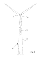
- a wind turbine 90 comprises a tower 92, a nacelle 94 at the tower top, the nacelle housing machine components, such as gearbox, generator etc. (not shown).
- a hub 96 supports a plurality of wind turbine blades 100.
- Fig. 2 shows a cross section of a wind turbine blade 100 according to the present invention.
- the blade comprises a main blade body 102 and a trailing edge section 104.
- the blade 100 comprises upper and lower skins 101 and 103. Trailing sections 105 and 107 of the main blade section may be flexible, elastic or springy, made e.g. from a suitable laminate.
- the main blade body 102 comprises spars 106 and 108. At a first projection 110 of spar 108, the trailing edge section 104 is movably connected to the main blade body at pivot 112.
- respective first ends of first and second actuator structures 118 and 120 are attached at pivots 122 and 124. Opposite second ends of the actuators 118 and 120 are attached at further pivots 126 and 128 to fulcrums 130 and 132 of the trailing edge section 104.
- Each of the actuator structures 118 and 120 comprises a stack of a plurality of piezoelectric elements 134, such as rings or circular plates of piezoelectric material.
- the stack of piezoelectric elements 134 and hence the actuator structures 118 and 120 are arranged so as to allow the actuator structures to operate as linear actuators for causing the trailing edge section 104 to move, deform or deflect relative to the main blade section 102.
- Displacement of the actuators 118 and 120 results in deflection of the trailing edge section 102 relative to the main blade section 102, as the trailing edge section 104 (flap) pivots around pivot joint 112.
- Operation of the actuators is appropriately controlled by a control system, which may e.g. cause the upper actuator 118 to extend its length and the lower actuator 120 to simultaneously reduce its length for deflection of the trailing edge section 104.
- the upper actuator 118 may be operated to reduce its length
- the lower actuator 120 may be operated to increase its length.
- the actuator structures 118 and 120 co-operate to provide a moment around the pivot joint 112, which is displaced from the points of attack at 126 and 128, with the fulcrums 130 and 132 acting as force amplifiers.
- Fig. 3 shows a first embodiment of the actuator structure 118 and 120 in more detail.
- the actuator structure shown comprises a force sensor 136 in the form of a dummy piezoelectric element, of which an electric signal may be tapped to measure the dynamic force that passes through in series, by quantifying the voltage or the charge that arises in it.
- Adjacent the stack of piezoelectric elements are insulating rings 138 and 140 of a ceramic material for protecting the actuators from lightning current.
- the stack of piezoelectric elements and the force sensor is held together under compressive load by a bolt 142 and a nut 144 in order to avoid the stack of piezoelectric elements to enter a tensile stress condition under the presence of an alternating wind load on the trailing edge section 104.
- the bolt head is optionally received in a housing element 144.
- Electrodes (not shown) for providing an operating voltage, charge or current to the stack of piezoelectric elements are connected to the stack of piezoelectric elements.
- Fig. 4 illustrates a second embodiment of the actuator structure 118 and 120 generally depicted in Fig. 2 .
- the actuator 118, 120 comprises a stack of piezoelectric elements 134, between which are arranged first activation electrodes 146 and second activation electrodes 148. Neighbouring piezoelectric elements share common electrodes 146 and 148, with the piezoelectric elements being arranged with their poling directions as indicated by arrows in Fig. 4 .
- a force sensor (not shown) may optionally be included in the stack of piezoelectric elements 134. At the respective ends of the stack of piezoelectric elements, insulating rings of a ceramic material are provided for lightning protection.
- the stack of piezoelectric elements 134 and the insulating rings 138, 140 are housed in U-shaped housing halves 150 and 152, which are held together by bolds 154 and 156, whereby the stack of piezoelectric elements is kept under compressive load in order to avoid the stack of piezoelectric elements to enter a tensile stress condition under the presence of an alternating wind load on the trailing edge section 104.
- the housing halves 150 and 152 form revolute joints 158 and 160 for attachment to the spar 108 of the main blade section and to the trailing edge section, respectively.
- a displacement sensor may be provided for measuring or determining the displacement of the actuators 118, 120.
- the stack 134 of piezoelectric elements is preferably controlled via electrodes, e.g. electrodes 146 and 148 as shown in the embodiment of Fig. 4 , to which a charge or current is provided in response to control commands generated in a control system (not shown).
Abstract
Description
- The present invention relates to wind turbine blades, notably wind turbine blades with displaceable trailing edge sections, also referred to as flaps, useful for altering the aerodynamic profile of the blade and thereby influencing the lift and drag forces on the overall blade structure. In particular, the invention relates to an actuator structure for causing the trailing edge section of a blade to move relative to a main blade portion, the actuator structure comprising a stack of piezoelectric elements.
- Trailing edge flaps are known to influence the aerodynamic characteristics of wind turbine blades.
WO 2004/088130 (Forskningscenter Risø, Bak et al. ) discloses a wind turbine blade comprising one or more shape deformable trailing edge airfoil sections comprising actuator means for providing shape changes in the shape deformable trailing airfoil sections.WO 2004/088130 discloses the use of 'smart materials' and mechanical actuators integrated in a deformable materiel changing the outer geometry in the leading and trailing edge region and thereby changing the blade section aerodynamic forces. Such 'smart materials' are said to deform once a voltage is applied to them. Preferred materials are said to include: shape memory alloys, piezoelectric materials, magnetostrictive materials, electrorheological fluids, electrochromic materials, electroactive polymers, chiral materials, conducting polymers, photoactive materials, thick and thin films, optical fibres, tunable dielectrics, self monitoring materials, self assembly materials, self repairing/healing materials, biomaterials, power supplies, power sources, and self powering, multilayer and composite materials and/or 'smart composites'. - It is an object of embodiments of the invention to provide an embodiment of the basic principle of a piezoelectric-based actuator disclosed in
WO 2004/088130 , which is accurate, reliable, has a high longevity, responses quickly to control commands or changes in aerodynamic loads, and which is lightning and fatigue resistive. - In a first aspect the present invention provides a wind turbine blade comprising a main blade body and trailing edge section movably connected to the main blade body, the blade further comprising:
- at least one actuator structure internally within the blade, the actuator structure being arranged such that it interconnects the trailing edge section and the main blade body, the actuator structure comprising a stack of a plurality of piezoelectric elements, so that the stack of piezoelectric elements is capable of operating as a linear actuator;
- the actuator structure being arranged such that it is capable of causing the trailing edge section to move or deform relative to the main blade body.
- The actuator structure may be controllable by voltage applied, e.g. via electrodes, to the stack of piezoelectric elements. It has been found that the use of a stack of piezoelectric elements renders the actuator structure reliable, stable and fatigue resistant. Moreover, it is easily controllable, e.g. in response to an applied voltage. The control of the actuating structure may conveniently be achieved by means of a control system, which applies voltage to the piezoelectric elements, for example in response to changes in the aerodynamic loads on the blade, absolute or relative wind velocity, turbulence, rotor rpm, desired power output or other parameters.
- Though the term 'piezoelectric elements' is consistently used herein, it should be understood that the piezoelectric elements may include or be substituted by any of the following elements or materials, whereby the effects and advantages of the invention are also achieved: shape memory alloys, piezoelectric materials, magnetostrictive materials, electrorheological fluids, electrochromic materials, electroactive polymers, chiral materials, conducting polymers, photoactive materials, thick and thin films, optical fibres, tunable dielectrics, self monitoring materials, self assembly materials, self repairing/healing materials, biomaterials, power supplies, power sources, and self powering, multilayer and composite materials and/or 'smart composites'.
- The invention also provides a wind turbine, in particular a horizontal axis wind turbine, comprising one or more blades according to the first aspect of the invention. In embodiments, in which the blade comprises electrodes in contact with the piezoelectric elements, the wind turbine preferably comprises a control system for controlling an activation voltage applied to the stack of piezoelectric elements through the electrodes, so as to thereby control the actuator structure. The control system may comprise a wind velocity meter and/or a load meter for measuring loads on the at least one blade, so as to allow the control system to control the at least actuator structure in response to the wind velocity and/or the load on the blade.
- The voltage for controlling the piezoelectric elements may be provided by means of one or more electrodes arranged in contact with the piezoelectric elements. For example, a control system may be provided for controlling an activation voltage applied to the stack of piezoelectric elements through said electrodes, so as to thereby control the actuator structure. The control system may control the stack of piezoelectric elements and hence the actuator structure in response to external input, e.g. a wind velocity measurement or blade load measured e.g. as a pressure on the surface of the blade, by means of one or more torque sensors at the root of the blade or by means of one or more strain gauges at the surface of the blade. The control of the actuator structure may also or alternatively be performed in response to a desired power output or a turbulence degree of the wind field. The control may be performed in response to instant measurements of wind velocity, turbulence, load, etc. or it may be performed in response to averaged data, e.g. on the basis of data sampled over a time span of e.g. two to five seconds up to 24 hours.
- In one convenient configuration of the stack of piezoelectric elements, neighboring piezoelectric elements are arranged in alternate poling directions, whereby the electrodes may be arranged between neighboring piezoelectric elements, which share common electrodes as they both are in contact with the same electrode. This configuration safes space and costs. However, other configurations are possible, in which neighboring electrodes are arranged with unidirectional poling directions.
- In order to avoid the stack of piezoelectric elements to enter a tensile stress condition due to aerodynamic load effects on the main blade body or trailing edge section, the stack of piezoelectric elements may be kept under a compressive load by a tensioning structure. In particular, an alternating wind load on the trailing edge section, i.e. flap, may cause the stack of piezoelectric elements to enter the tensile stress condition, however this risk is avoided by keeping the elements under compressive load. The tensioning structure may comprise mechanical tensioning elements for providing the required compressive load to the stack.
- With a view to protecting the stack of piezoelectric elements against lightning effects or other non-desirable or non-controllable electrical effects, the actuator structure is preferably electrically insulated from the surface of the blade. For example, the actuator structure may comprise electrically insulating elements at both ends of the stack of piezoelectric elements, thereby providing electric insulation between the piezoelectric elements and the control system on the one hand and their surroundings on the other hand. Optionally, a circumferential insulation element or layer may be provided around the stack of piezoelectric elements as well to provide further protection.
- The insulating elements or layers may e.g. comprise a ceramic material, a plastics or polymeric material, wood, or a composite material including e.g. one or more of the aforementioned materials. They should have a thickness, which is sufficient to sustain a lightning attack.
- In one embodiment of the present invention, the trailing edge section is pivotally connected to the main blade body at an attachment point located between an upper and a lower skin of the blade. A first end of the actuator structure is preferably connected to the main blade body, preferably at a pivot joint, and a second end of the actuator, which is opposite to said first end, is preferably connected the trailing edge section, preferably also at a pivot joint. The attachment point of the second end of the actuator structure and the trailing edge section is preferably at a point distant from the attachment point of the trailing edge section itself to the main blade section. In this way, a moment can be applied to the trailing edge section.
- The first end of the actuator structure, which is connected to the main blade section may conveniently be connected to a spar in the main blade section. That end of the actuator structure, which is directly or indirectly connected to the trailing edge section may be connected to a lever which acts as a fulcrum, such that a moment amplification is obtained.
- A plurality of actuator structures may be provided. For example, actuator structures may, in a chordwise cross section of the blade, be provided at opposite sides of the pivotal interconnection between the main blade section and the trailing edge section, so as to thereby achieve that the two actuator sections provide a common moment to the trailing edge section around the pivot point. In other embodiments, a plurality of actuator structures may be provided for controlling a plurality of separate flaps (i.e. trailing edge sections) arranged next to each other or at mutual distances in the spanwise direction of the blade. In such embodiments, the separate trailing edge sections may be individually controllable, or they may be controlled by control commands common to all trailing edge sections.
- A force sensor may be comprised within the stack of piezoelectric elements. For example, one piezoelectric element may be configured as a dummy, of which an electric signal may be tapped to measure the dynamic force that passes there through by quantifying the voltage or the charge that arises in it.
- Further, the actuator structure may comprise a displacement sensor for detecting the displacement of the actuator structure. For example, the displacement sensor may be embodied by a contact or non-contact, e.g. optical displacement sensor adjacent to or in the vicinity of the actuator structure.
- The output signals produced by the force sensor and/or displacement sensor may be passed to the control system for controlling the movement of the trailing edge section, so as to allow the control system to use the signals for control purposes. In one embodiment, the control system may use the detected force to deflect the trailing edge section further, if the detected force is below a certain value, indicating low load, or analogously to reduce deflection if the force passing through the actuator structure is above a threshold value. Also, a measured displacement of the actuator structure may e.g. be used by the control system to pass a further signal onto a system for controlling the pitch of the blade. For example, in case deflection is already at its maximum in a given situation, where more thrust on the blades of a wind turbine is desirable, the pitch of the blade may be reduced to achieve the desired thrust or load increase. Alternatively, if the actuator displacement is not at its maximum, a general control system of the wind turbine may be configured to decide if (a) pitch is to be decreased, or (b) the trailing edge section is to be deflected further, or (c) changes in the power-generating control are to be performed, e.g. a change of the level of magnetization of the rotor of a synchronous generator of the wind turbine. Such decisions may e.g. be based on wind velocities, turbulence levels, blade loads, rotor rpm, generated power, etc.
- Generally, the control of the actuator structure of the trailing edge section may preferably be coupled to or integrated with other control elements of the wind turbine.
-
- Fig. 1
- generally illustrates a wind turbine;
- Fig. 2
- shows a cross section of a wind turbine blade according to the present invention;
- Fig. 3
- shows a first embodiment of an actuator structure for a wind turbine blade of the present invention;
- Fig. 4
- shows a second embodiment of an actuator structure for a wind turbine blade of the present invention.
- As shown in
Fig. 1 , awind turbine 90 comprises atower 92, anacelle 94 at the tower top, the nacelle housing machine components, such as gearbox, generator etc. (not shown). At an upwind end of the nacelle, ahub 96 supports a plurality ofwind turbine blades 100. -
Fig. 2 shows a cross section of awind turbine blade 100 according to the present invention. The blade comprises amain blade body 102 and a trailingedge section 104. Theblade 100 comprises upper andlower skins sections main blade body 102 comprisesspars first projection 110 ofspar 108, the trailingedge section 104 is movably connected to the main blade body atpivot 112. At second andthird projections spar 108, respective first ends of first andsecond actuator structures pivots actuators further pivots fulcrums edge section 104. - Each of the
actuator structures piezoelectric elements 134, such as rings or circular plates of piezoelectric material. The stack ofpiezoelectric elements 134 and hence theactuator structures edge section 104 to move, deform or deflect relative to themain blade section 102. - Displacement of the
actuators edge section 102 relative to themain blade section 102, as the trailing edge section 104 (flap) pivots around pivot joint 112. Operation of the actuators is appropriately controlled by a control system, which may e.g. cause theupper actuator 118 to extend its length and thelower actuator 120 to simultaneously reduce its length for deflection of the trailingedge section 104. Likewise, for reducing deflection of the trailingedge section 104, theupper actuator 118 may be operated to reduce its length, and thelower actuator 120 may be operated to increase its length. It will be appreciated that, in the embodiment shown inFig. 2 , theactuator structures fulcrums -
Fig. 3 shows a first embodiment of theactuator structure piezoelectric elements 134, the actuator structure shown comprises aforce sensor 136 in the form of a dummy piezoelectric element, of which an electric signal may be tapped to measure the dynamic force that passes through in series, by quantifying the voltage or the charge that arises in it. Adjacent the stack of piezoelectric elements are insulatingrings bolt 142 and anut 144 in order to avoid the stack of piezoelectric elements to enter a tensile stress condition under the presence of an alternating wind load on the trailingedge section 104. The bolt head is optionally received in ahousing element 144. - Electrodes (not shown) for providing an operating voltage, charge or current to the stack of piezoelectric elements are connected to the stack of piezoelectric elements.
-
Fig. 4 illustrates a second embodiment of theactuator structure Fig. 2 . Though the embodiment ofFig. 4 in its implementation differs from the embodiment ofFig. 3 , like elements are given the same reference numbers inFig. 4 as inFig. 3 . Theactuator piezoelectric elements 134, between which are arrangedfirst activation electrodes 146 andsecond activation electrodes 148. Neighbouring piezoelectric elements sharecommon electrodes Fig. 4 . A force sensor (not shown) may optionally be included in the stack ofpiezoelectric elements 134. At the respective ends of the stack of piezoelectric elements, insulating rings of a ceramic material are provided for lightning protection. - The stack of
piezoelectric elements 134 and the insulatingrings U-shaped housing halves bolds edge section 104. - The
housing halves revolute joints spar 108 of the main blade section and to the trailing edge section, respectively. - In addition to the elements shown in the drawings, a displacement sensor may be provided for measuring or determining the displacement of the
actuators - In the embodiments shown herein, the
stack 134 of piezoelectric elements is preferably controlled via electrodes,e.g. electrodes Fig. 4 , to which a charge or current is provided in response to control commands generated in a control system (not shown).
Claims (18)
- A wind turbine blade comprising a main blade body and trailing edge section movably connected to the main blade body, the blade further comprising:- at least one actuator structure internally within the blade, the actuator structure being arranged such that it interconnects the trailing edge section and the main blade body, the actuator structure comprising a stack of a plurality of piezoelectric elements, so that the stack of piezoelectric elements is capable of operating as a linear actuator;- the actuator structure being arranged such that it is capable of causing the trailing edge section to move or deform relative to the main blade body.
- A wind turbine blade according to claim 1, further comprising electrodes in contact with the piezoelectric elements, and a control system for controlling an activation voltage applied to the stack of piezoelectric elements through said electrodes, so as to thereby control the actuator structure.
- A wind turbine according to claim 2, wherein the piezoelectric elements are arranged in alternate poling directions, and wherein the electrodes are arranged between neighboring piezoelectric elements, which share common electrodes.
- A wind turbine blade according to any of the preceding claims, further comprising a tensioning structure for keeping the stack of piezoelectric elements under a compressive load.
- A wind turbine blade according to any of the preceding claims, wherein the actuator structure is electrically insulated from skins of the main blade section and the trailing edge section.
- A wind turbine according to claim 5, wherein the actuator structure comprises electrically insulating elements at both ends of the stack of piezoelectric elements.
- A wind turbine blade according to claim 6, wherein the insulating elements comprise a ceramic material, a polymeric material or a composite material.
- A wind turbine blade according to claim 6 or 7, wherein the insulating elements have a thickness, which is sufficient to sustain a lightning attack.
- A wind turbine blade according to any of the preceding claims, wherein the trailing edge section is pivotally connected to the main blade body at an attachment point located between an upper and a lower skin of the blade, and wherein a first end of the actuator structure is connected to the main blade body, and a second end of the actuator, which is opposite to said first end, is connected the trailing edge section at a point distant from said attachment point of the trailing edge section.
- A wind turbine blade according to any of the preceding claims, wherein said at least one actuator structure comprises a plurality of actuator structures.
- A wind turbine blade according to claims 9 and 10, wherein the plurality of actuator structures comprises a first and a second actuator structure arranged at respective of said attachment point of the trailing edge section, so as to allow them to apply a moment to the trailing edge section.
- A wind turbine blade according to any of the preceding claims, further comprising a force sensor within the stack of piezoelectric elements.
- A wind turbine blade according to claim 12, wherein the force sensor comprises a dummy piezoelectric element.
- A wind turbine blade according to any of the preceding claims, wherein the actuator structure further comprises a displacement sensor for detecting the displacement of the actuator structure.
- A wind turbine blade according to any of the preceding claims, wherein the trailing edge section forms a trailing edge flap.
- A wind turbine comprising at least one wind turbine blade comprising a main blade body and trailing edge section movably connected to the main blade body, the blade further comprising:- at least one actuator structure internally within the blade, the actuator structure being arranged such that it interconnects the trailing edge section and the main blade body, the actuator structure comprising a stack of a plurality of piezoelectric elements, so that the stack of piezoelectric elements is capable of operating as a linear actuator;- the actuator structure being arranged such that it is capable of causing the trailing edge section to move or deform relative to the main blade body.
- A wind turbine according to claim 16, wherein the blade further comprises electrodes in contact with the piezoelectric elements, and wherein the wind turbine comprises a control system for controlling an activation voltage applied to the stack of piezoelectric elements through said electrodes, so as to thereby control the actuator structure.
- A wind turbine according to claim 17, wherein the control system further comprises a wind velocity meter and/or a load meter for measuring loads on the at least one blade, the control system being configured to control the at least actuator structure in response to the instant wind velocity and/or the instant load on the blades.
Applications Claiming Priority (2)
| Application Number | Priority Date | Filing Date | Title |
|---|---|---|---|
| US16366309P | 2009-03-26 | 2009-03-26 | |
| DKPA200900420A DK200900420A (en) | 2009-03-26 | 2009-03-26 | A wind turbine blade comprising a trailing edge flap and a piezoelectric actuator |
Publications (2)
| Publication Number | Publication Date |
|---|---|
| EP2233735A2 true EP2233735A2 (en) | 2010-09-29 |
| EP2233735A3 EP2233735A3 (en) | 2014-04-09 |
Family
ID=42224597
Family Applications (1)
| Application Number | Title | Priority Date | Filing Date |
|---|---|---|---|
| EP10157166.9A Withdrawn EP2233735A3 (en) | 2009-03-26 | 2010-03-22 | A wind turbine blade comprising a trailing edge flap and a piezoelectric actuator |
Country Status (4)
| Country | Link |
|---|---|
| US (1) | US7922450B2 (en) |
| EP (1) | EP2233735A3 (en) |
| CN (2) | CN201757024U (en) |
| DK (1) | DK200900420A (en) |
Cited By (13)
| Publication number | Priority date | Publication date | Assignee | Title |
|---|---|---|---|---|
| CN102085918A (en) * | 2010-12-31 | 2011-06-08 | 北京控制工程研究所 | Binary intelligent structure control device of satellite flexible vibration |
| GB2486876A (en) * | 2010-12-20 | 2012-07-04 | Vestas Wind Sys As | Wind turbine blade flap |
| EP2669509A1 (en) * | 2012-05-29 | 2013-12-04 | SE Blades Technology B.V. | Actuator element |
| EP2998571A1 (en) | 2014-09-19 | 2016-03-23 | Siemens Aktiengesellschaft | Lift influencing device for a rotor blade of a wind turbine |
| EP3128169A1 (en) * | 2015-08-07 | 2017-02-08 | Siemens Aktiengesellschaft | Rotor blade with actuator arrangement |
| CN110107455A (en) * | 2019-05-20 | 2019-08-09 | 沈阳航空航天大学 | A kind of fish tail swing formula blade of vertical axis wind turbine |
| WO2019170656A1 (en) | 2018-03-08 | 2019-09-12 | Mubea Carbo Tech Gmbh | Wind turbine blade |
| US20210363961A1 (en) * | 2018-04-28 | 2021-11-25 | The Research Foundation For The State University Of New York | Flexible wind turbine blade with actively variable twist distribution |
| WO2022019852A1 (en) * | 2020-07-23 | 2022-01-27 | Tusas- Turk Havacilik Ve Uzay Sanayii Anonim Sirketi | An actuator mechanism |
| WO2022019856A1 (en) | 2020-07-23 | 2022-01-27 | Tusas- Turk Havacilik Ve Uzay Sanayii Anonim Sirketi | Actuator setup |
| WO2022019858A1 (en) | 2020-07-23 | 2022-01-27 | Tusas- Turk Havacilik Ve Uzay Sanayii Anonim Sirketi | An actuator mechanism |
| WO2022019857A1 (en) | 2020-07-23 | 2022-01-27 | Tusas- Turk Havacilik Ve Uzay Sanayii Anonim Sirketi | A control surface system |
| WO2022019854A1 (en) | 2020-07-23 | 2022-01-27 | Tusas- Turk Havacilik Ve Uzay Sanayii Anonim Sirketi | A control surface system |
Families Citing this family (29)
| Publication number | Priority date | Publication date | Assignee | Title |
|---|---|---|---|---|
| US8232664B2 (en) * | 2008-08-25 | 2012-07-31 | Mark R. Stroup | Vertical axis wind turbine |
| DK200900420A (en) * | 2009-03-26 | 2010-09-27 | Vestas Wind Sys As | A wind turbine blade comprising a trailing edge flap and a piezoelectric actuator |
| EP2333322A3 (en) * | 2009-11-30 | 2017-02-22 | Vestas Wind Systems A/S | Measuring loads on wind turbine blades |
| ES2616543T3 (en) * | 2010-07-06 | 2017-06-13 | Lm Wp Patent Holding A/S | Wind turbine blade with variable output edge |
| CN102305167B (en) * | 2011-07-07 | 2014-03-19 | 安义 | Waterflow source and airflow source power composite rudder blade element |
| US8506248B2 (en) | 2011-10-06 | 2013-08-13 | General Electric Company | Wind turbine rotor blade with passively modified trailing edge component |
| US8602732B2 (en) | 2011-10-06 | 2013-12-10 | General Electric Company | Wind turbine rotor blade with passively modified trailing edge component |
| DK2757254T3 (en) * | 2013-01-21 | 2016-09-05 | Alstom Wind Slu | Wind turbine blade |
| CN103291539B (en) * | 2013-05-09 | 2015-05-13 | 哈尔滨工业大学 | Blade swing wing design method and H-type vertical axis wind turbine with blade swing wings |
| EP2865887B1 (en) * | 2013-10-24 | 2016-06-01 | Alstom Renovables España, S.L. | Wind turbine blade |
| EP2899395B1 (en) * | 2014-01-23 | 2017-04-12 | Alstom Renovables España, S.L. | Wind turbine blades |
| DK2908001T3 (en) | 2014-02-12 | 2017-01-02 | Siemens Ag | Means for damping load on a wind turbine rotor blade |
| WO2015139130A1 (en) * | 2014-03-17 | 2015-09-24 | Manconi John William | Piezoelectric enhanced windmill |
| GB2537630B (en) * | 2015-04-21 | 2020-11-04 | Agustawestland Ltd | An aerofoil |
| US10442525B2 (en) * | 2016-05-07 | 2019-10-15 | Optivector Ltd | Rotor or propeller blade with dynamically variable geometry and other properties |
| DE102016116138A1 (en) * | 2016-08-30 | 2018-03-01 | Wobben Properties Gmbh | Actuator device for a wind turbine, wind turbine and assembly method |
| DE102017129708B4 (en) | 2017-12-13 | 2022-05-12 | cp.max Rotortechnik GmbH & Co. KG | Trailing edge flap for a rotor blade |
| CN108298062B (en) * | 2018-01-15 | 2021-03-12 | 上海理工大学 | Self-restrained adaptive flap |
| DE102018100963A1 (en) | 2018-01-17 | 2019-07-18 | Wobben Properties Gmbh | Wind turbine and rotor blade for a wind turbine |
| CN108374751B (en) * | 2018-01-25 | 2020-01-21 | 上海理工大学 | Sectional type blade device capable of automatically opening and closing wing gap jet flow |
| ES2825025T3 (en) | 2018-01-29 | 2021-05-14 | Siemens Gamesa Renewable Energy As | Trailing edge assembly |
| DE102018104731A1 (en) * | 2018-03-01 | 2019-09-05 | Wobben Properties Gmbh | Actuator device for a wind turbine, wind turbine and assembly method |
| CN110792554B (en) * | 2018-08-03 | 2020-12-11 | 兰州理工大学 | Deformation type wind driven generator blade |
| US11408394B2 (en) * | 2018-09-17 | 2022-08-09 | Siemens Gamesa Renewable Energy A/S | Sensor device for an aerodynamic element |
| EP3730779A1 (en) * | 2019-04-25 | 2020-10-28 | Siemens Gamesa Renewable Energy A/S | Fluid convey tubing system for wind turbine rotor blade |
| CN110486227B (en) * | 2019-08-07 | 2021-10-19 | 河海大学 | Wind power generation system based on active protection of wind environment and protection method thereof |
| CN111749844A (en) * | 2020-07-17 | 2020-10-09 | 中国人民解放军63821部队 | Vertical axis wind turbine blade with variable trailing edge and vertical axis wind turbine |
| DE102021005965B3 (en) | 2021-12-01 | 2022-11-10 | Friedrich Grimm | ROTOR BLADE FOR A WIND OR WATER TURBINE AND FOR A ROTARY WING VEHICLE AND PARTICULARLY FOR A HELICOPTER |
| CN116163896B (en) * | 2023-04-26 | 2023-07-11 | 山东科技大学 | High-frequency micro-vibration measuring and inhibiting system based on megawatt wind turbine blade |
Citations (1)
| Publication number | Priority date | Publication date | Assignee | Title |
|---|---|---|---|---|
| WO2004088130A1 (en) | 2003-03-31 | 2004-10-14 | Forskningscenter Risø | Control of power, loads and/or stability of a horizontal axis wind turbine by use of variable blade geometry control |
Family Cites Families (17)
| Publication number | Priority date | Publication date | Assignee | Title |
|---|---|---|---|---|
| DE2922885A1 (en) * | 1979-06-06 | 1980-12-18 | Wolfgang Rath | Wind driven power generator - has flaps on ends of blades given oscillating movement to produce to rotate impeller in and out of wind |
| US4396852A (en) * | 1981-07-10 | 1983-08-02 | Hunt Arlon J | Windmill |
| FR2768994B1 (en) * | 1997-09-30 | 2001-12-21 | Deutsch Zentr Luft & Raumfahrt | PROFILE |
| US6135713A (en) | 1999-01-19 | 2000-10-24 | The Mcdonnell Douglas Helicopter Company | Helicopter rotor blade flap actuator government interest |
| US6231013B1 (en) | 1999-06-16 | 2001-05-15 | Daimlerchrysler Ag | Airfoil member with a piezoelectrically actuated servo-flap |
| DE10054643B4 (en) * | 2000-11-03 | 2008-06-05 | Deutsches Zentrum für Luft- und Raumfahrt e.V. | Component with controllable deformation |
| US6481667B1 (en) * | 2001-03-05 | 2002-11-19 | Northrop Grumman Corporation | System and method for deflecting an aerodynamic control surface |
| DE10126918A1 (en) | 2001-06-01 | 2002-12-19 | Eads Deutschland Gmbh | High power piezoactuator e.g. for use in helicopters, has thermally conductive material between individual sub-actuators and in thermally conductive contact with the sub-actuators on either side |
| DE10214984B4 (en) * | 2002-04-04 | 2006-01-19 | Eads Deutschland Gmbh | Actuator and sensor system for composite structures |
| US6769873B2 (en) * | 2002-10-08 | 2004-08-03 | The United States Of America As Represented By The Secretary Of The Navy | Dynamically reconfigurable wind turbine blade assembly |
| EP1597476A1 (en) | 2003-02-18 | 2005-11-23 | Forskningscenter Riso | Method of controlling aerodynamic load of a wind turbine based on local blade flow measurement |
| DK200300670A (en) | 2003-05-05 | 2004-11-06 | Lm Glasfiber As | Wind turbine with buoyancy regulating organs |
| EP1745214B2 (en) | 2004-05-11 | 2020-04-29 | Weidmüller Monitoring Systems GmbH | Method for controlling the rotor blades of a wind power station and wind power station comprising a measuring system for carrying out said method |
| US7360996B2 (en) * | 2005-12-07 | 2008-04-22 | General Electric Company | Wind blade assembly and method for damping load or strain |
| CN101207313B (en) * | 2006-12-22 | 2011-03-30 | 财团法人工业技术研究院 | Electric generating apparatus with combined generator and power generation method thereof |
| EP2222955B1 (en) * | 2007-10-29 | 2017-01-11 | Vestas Wind Systems A/S | Wind turbine blade and method for controlling the load on a blade |
| DK200900420A (en) * | 2009-03-26 | 2010-09-27 | Vestas Wind Sys As | A wind turbine blade comprising a trailing edge flap and a piezoelectric actuator |
-
2009
- 2009-03-26 DK DKPA200900420A patent/DK200900420A/en not_active Application Discontinuation
-
2010
- 2010-03-22 EP EP10157166.9A patent/EP2233735A3/en not_active Withdrawn
- 2010-03-24 US US12/730,810 patent/US7922450B2/en not_active Expired - Fee Related
- 2010-03-26 CN CN2010202103457U patent/CN201757024U/en not_active Expired - Fee Related
- 2010-03-26 CN CN201010188021A patent/CN101865076A/en active Pending
Patent Citations (1)
| Publication number | Priority date | Publication date | Assignee | Title |
|---|---|---|---|---|
| WO2004088130A1 (en) | 2003-03-31 | 2004-10-14 | Forskningscenter Risø | Control of power, loads and/or stability of a horizontal axis wind turbine by use of variable blade geometry control |
Cited By (16)
| Publication number | Priority date | Publication date | Assignee | Title |
|---|---|---|---|---|
| GB2486876A (en) * | 2010-12-20 | 2012-07-04 | Vestas Wind Sys As | Wind turbine blade flap |
| CN102085918A (en) * | 2010-12-31 | 2011-06-08 | 北京控制工程研究所 | Binary intelligent structure control device of satellite flexible vibration |
| CN102085918B (en) * | 2010-12-31 | 2013-03-13 | 北京控制工程研究所 | Binary intelligent structure control device of satellite flexible vibration |
| EP2669509A1 (en) * | 2012-05-29 | 2013-12-04 | SE Blades Technology B.V. | Actuator element |
| US10408192B2 (en) | 2014-09-19 | 2019-09-10 | Siemens Gamesa Renewable Energy A/S | Lift influencing device for a rotor blade of a wind turbine |
| EP2998571A1 (en) | 2014-09-19 | 2016-03-23 | Siemens Aktiengesellschaft | Lift influencing device for a rotor blade of a wind turbine |
| EP3128169A1 (en) * | 2015-08-07 | 2017-02-08 | Siemens Aktiengesellschaft | Rotor blade with actuator arrangement |
| WO2017025352A1 (en) * | 2015-08-07 | 2017-02-16 | Siemens Aktiengesellschaft | Rotor blade with actuator arrangement |
| WO2019170656A1 (en) | 2018-03-08 | 2019-09-12 | Mubea Carbo Tech Gmbh | Wind turbine blade |
| US20210363961A1 (en) * | 2018-04-28 | 2021-11-25 | The Research Foundation For The State University Of New York | Flexible wind turbine blade with actively variable twist distribution |
| CN110107455A (en) * | 2019-05-20 | 2019-08-09 | 沈阳航空航天大学 | A kind of fish tail swing formula blade of vertical axis wind turbine |
| WO2022019852A1 (en) * | 2020-07-23 | 2022-01-27 | Tusas- Turk Havacilik Ve Uzay Sanayii Anonim Sirketi | An actuator mechanism |
| WO2022019856A1 (en) | 2020-07-23 | 2022-01-27 | Tusas- Turk Havacilik Ve Uzay Sanayii Anonim Sirketi | Actuator setup |
| WO2022019858A1 (en) | 2020-07-23 | 2022-01-27 | Tusas- Turk Havacilik Ve Uzay Sanayii Anonim Sirketi | An actuator mechanism |
| WO2022019857A1 (en) | 2020-07-23 | 2022-01-27 | Tusas- Turk Havacilik Ve Uzay Sanayii Anonim Sirketi | A control surface system |
| WO2022019854A1 (en) | 2020-07-23 | 2022-01-27 | Tusas- Turk Havacilik Ve Uzay Sanayii Anonim Sirketi | A control surface system |
Also Published As
| Publication number | Publication date |
|---|---|
| US7922450B2 (en) | 2011-04-12 |
| CN101865076A (en) | 2010-10-20 |
| US20100247314A1 (en) | 2010-09-30 |
| DK200900420A (en) | 2010-09-27 |
| EP2233735A3 (en) | 2014-04-09 |
| CN201757024U (en) | 2011-03-09 |
Similar Documents
| Publication | Publication Date | Title |
|---|---|---|
| US7922450B2 (en) | Wind turbine blade comprising a trailing edge flap and a piezoelectric actuator | |
| CA2521045C (en) | Control of power, loads and/or stability of a horizontal axis wind turbine by use of variable blade geometry control | |
| EP2019203B2 (en) | Wind turbine blade with cambering flaps | |
| EP2222955B1 (en) | Wind turbine blade and method for controlling the load on a blade | |
| EP2865890B1 (en) | Wind turbine blade | |
| US10247169B2 (en) | Means for alleviating strain on a wind turbine rotor blade | |
| US8408870B2 (en) | Wind turbine blade with cambering flaps controlled by surface pressure changes | |
| EP2808541A2 (en) | Wind turbine blade having a tensile-only stiffener for passive control of flap movement | |
| EP2273106B1 (en) | Wind turbine aerodynamic separation control | |
| EP2848805A1 (en) | Method of operating a wind turbine | |
| KR20150080845A (en) | Apparatus and method of controlling blade for a wind power generator, and a wind power generator using the same | |
| WO2015176868A1 (en) | Aerodynamic device of a rotor blade of a wind turbine | |
| CN102116259A (en) | Wind turbine rotor blades including controllable depressions | |
| Madsen et al. | A morphing trailing edge flap system for wind turbine blades | |
| US20170107976A1 (en) | Determining a deflection of a rotor blade of a wind turbine | |
| Opitz et al. | Bench test of a full-scale active twist blade segment | |
| WO2012083961A1 (en) | Wind turbine blades | |
| WO2022069189A1 (en) | Wind turbine component, wind turbine, and method for manufacturing of a wind turbine component | |
| Cairns et al. | Design and feasibility of active control surfaces on wind turbine blade systems | |
| DK201270436A (en) | Wind turbine blade having a flap | |
| Oh et al. | CONDITION MONITORING OF WIND TURBINE BLADE US-ING FIBER BRAGG GRATING SENSORS | |
| Vos | Post-buckled precompressed elements: a new class of flight control actuators enhancing morphing wing uavs |
Legal Events
| Date | Code | Title | Description |
|---|---|---|---|
| PUAI | Public reference made under article 153(3) epc to a published international application that has entered the european phase |
Free format text: ORIGINAL CODE: 0009012 |
|
| 17P | Request for examination filed |
Effective date: 20100422 |
|
| AK | Designated contracting states |
Kind code of ref document: A2 Designated state(s): AT BE BG CH CY CZ DE DK EE ES FI FR GB GR HR HU IE IS IT LI LT LU LV MC MK MT NL NO PL PT RO SE SI SK SM TR |
|
| AX | Request for extension of the european patent |
Extension state: AL BA ME RS |
|
| RAP1 | Party data changed (applicant data changed or rights of an application transferred) |
Owner name: VESTAS WIND SYSTEMS A/S |
|
| PUAL | Search report despatched |
Free format text: ORIGINAL CODE: 0009013 |
|
| AK | Designated contracting states |
Kind code of ref document: A3 Designated state(s): AT BE BG CH CY CZ DE DK EE ES FI FR GB GR HR HU IE IS IT LI LT LU LV MC MK MT NL NO PL PT RO SE SI SK SM TR |
|
| AX | Request for extension of the european patent |
Extension state: AL BA ME RS |
|
| RIC1 | Information provided on ipc code assigned before grant |
Ipc: F03D 3/06 20060101AFI20140228BHEP Ipc: F03D 1/06 20060101ALI20140228BHEP Ipc: F03D 7/02 20060101ALI20140228BHEP |
|
| STAA | Information on the status of an ep patent application or granted ep patent |
Free format text: STATUS: THE APPLICATION IS DEEMED TO BE WITHDRAWN |
|
| 18D | Application deemed to be withdrawn |
Effective date: 20141001 |