EP2187045A1 - Windmill blade and wind power generator using same - Google Patents
Windmill blade and wind power generator using same Download PDFInfo
- Publication number
- EP2187045A1 EP2187045A1 EP07832082A EP07832082A EP2187045A1 EP 2187045 A1 EP2187045 A1 EP 2187045A1 EP 07832082 A EP07832082 A EP 07832082A EP 07832082 A EP07832082 A EP 07832082A EP 2187045 A1 EP2187045 A1 EP 2187045A1
- Authority
- EP
- European Patent Office
- Prior art keywords
- blade
- angle
- attack
- wind turbine
- turbine blade
- Prior art date
- Legal status (The legal status is an assumption and is not a legal conclusion. Google has not performed a legal analysis and makes no representation as to the accuracy of the status listed.)
- Withdrawn
Links
- 230000003247 decreasing effect Effects 0.000 claims abstract description 60
- 230000007423 decrease Effects 0.000 claims abstract description 16
- 230000005611 electricity Effects 0.000 claims description 2
- 230000015556 catabolic process Effects 0.000 description 9
- 238000006731 degradation reaction Methods 0.000 description 9
- 238000010248 power generation Methods 0.000 description 5
- 238000013461 design Methods 0.000 description 4
- 238000013459 approach Methods 0.000 description 2
- 230000000694 effects Effects 0.000 description 2
- 238000009434 installation Methods 0.000 description 2
- 238000005452 bending Methods 0.000 description 1
- 238000007664 blowing Methods 0.000 description 1
- 239000011152 fibreglass Substances 0.000 description 1
- 238000005259 measurement Methods 0.000 description 1
- 238000012986 modification Methods 0.000 description 1
- 230000004048 modification Effects 0.000 description 1
- 230000002093 peripheral effect Effects 0.000 description 1
- 238000013519 translation Methods 0.000 description 1
Images


Classifications
-
- F—MECHANICAL ENGINEERING; LIGHTING; HEATING; WEAPONS; BLASTING
- F03—MACHINES OR ENGINES FOR LIQUIDS; WIND, SPRING, OR WEIGHT MOTORS; PRODUCING MECHANICAL POWER OR A REACTIVE PROPULSIVE THRUST, NOT OTHERWISE PROVIDED FOR
- F03D—WIND MOTORS
- F03D1/00—Wind motors with rotation axis substantially parallel to the air flow entering the rotor
- F03D1/06—Rotors
- F03D1/0608—Rotors characterised by their aerodynamic shape
- F03D1/0633—Rotors characterised by their aerodynamic shape of the blades
- F03D1/0641—Rotors characterised by their aerodynamic shape of the blades of the section profile of the blades, i.e. aerofoil profile
-
- F—MECHANICAL ENGINEERING; LIGHTING; HEATING; WEAPONS; BLASTING
- F05—INDEXING SCHEMES RELATING TO ENGINES OR PUMPS IN VARIOUS SUBCLASSES OF CLASSES F01-F04
- F05B—INDEXING SCHEME RELATING TO WIND, SPRING, WEIGHT, INERTIA OR LIKE MOTORS, TO MACHINES OR ENGINES FOR LIQUIDS COVERED BY SUBCLASSES F03B, F03D AND F03G
- F05B2240/00—Components
- F05B2240/20—Rotors
- F05B2240/30—Characteristics of rotor blades, i.e. of any element transforming dynamic fluid energy to or from rotational energy and being attached to a rotor
- F05B2240/301—Cross-section characteristics
-
- Y—GENERAL TAGGING OF NEW TECHNOLOGICAL DEVELOPMENTS; GENERAL TAGGING OF CROSS-SECTIONAL TECHNOLOGIES SPANNING OVER SEVERAL SECTIONS OF THE IPC; TECHNICAL SUBJECTS COVERED BY FORMER USPC CROSS-REFERENCE ART COLLECTIONS [XRACs] AND DIGESTS
- Y02—TECHNOLOGIES OR APPLICATIONS FOR MITIGATION OR ADAPTATION AGAINST CLIMATE CHANGE
- Y02E—REDUCTION OF GREENHOUSE GAS [GHG] EMISSIONS, RELATED TO ENERGY GENERATION, TRANSMISSION OR DISTRIBUTION
- Y02E10/00—Energy generation through renewable energy sources
- Y02E10/70—Wind energy
- Y02E10/72—Wind turbines with rotation axis in wind direction
Definitions
- the present invention relates to a wind turbine blade and a wind power generator that generates power using the same.
- Wind power generators have problems of noise generated from blades.
- the main causes of blade-generated noise are a blade tip vortex and a turbulent-flow boundary layer generated on the blade surface. It is thought that decreasing the rotational speed of a rotor is effective in reducing the noise level. Specifically, decreasing the rotational speed of the rotor decreases the inlet velocity of air to the blades, thereby allowing aerodynamic sound to be reduced. However, decreasing the rotational speed of the rotor has a problem of decreasing the power generation efficiency.
- Patent Citation 1 For reducing noise at a high-noise blade tip portion, for example, an approach disclosed in Patent Citation 1 has been proposed. This prevents noise by curving or bending the blade tip portion on the blade surface toward the trailing edge of the blade (a so-called sweptback wing) and/or providing a small blade (a so-called winglet) that is bent toward a positive pressure surface so as to intersect the blade tip portion to thereby decrease the vortex at the blade tip portion.
- Patent Citation 1 Japanese Translation of PCT International Application, Publication No. 2006-521483
- the present invention is made in consideration of the circumstances described above, and it is an object thereof to provide a wind turbine blade that can reduce the thickness of the turbulent-flow boundary layer generated on the blade surface at the blade tip portion to prevent noise generated at the trailing edge portion effectively, as well as a wind power generator using the same.
- a wind turbine blade having an airfoil shape in cross section, wherein an angle-of-attack decreasing portion that decreases an angle of attack during rotation at at least a predetermined rotational speed is provided over a predetermined range from a blade tip to a blade root side.
- the angle-of-attack decreasing portion decreases the angle of attack during rotation at at least the predetermined rotational speed over a predetermined range from the blade tip to the blade root side
- the thickness of the boundary layer on the blade surface of the predetermined range from the blade tip to the blade root side can be decreased during operation.
- the decrease in thickness of the boundary layer can prevent the occurrence of a vortex at the trailing edge of the blade, thus reducing noise.
- the angle-of-attack decreasing portion is provided at the tip portion of the wind turbine blade at which high noise is generated, noise can be reduced effectively. This eliminates the need for decreasing the rotational speed to reduce the noise, which can prevent a degradation in performance, such as a degradation in power generation efficiency.
- the lift generated is decreased with a decrease in angle of attack; therefore, it is preferable to set the range in which the angle-of-attack decreasing portion is provided in consideration of the influence on the performance of the blade and the noise reduction effect.
- This range is set, for example, within 20% of the blade length, preferably, within 10%.
- the predetermined rotational speed is set to, for example, a rotational speed at which the wind power generator outputs rated power, that is, a rated rotational speed.
- the angle-of-attack decreasing portion may be formed so that the angle of attack gradually decreases from the angle of attack of the blade root side toward the blade tip.
- the angle-of-attack decreasing portion is formed such that it is twisted so that the angle of the blade with respect to the wind inflow direction decreases gradually toward the blade tip, that is, a twist angle is applied to the blade tip portion. This makes the angle of attack of the angle-of-attack decreasing portion always differ from the blade root side irrespective of the rotational speed, which can reduce noise in a wide rotational speed range.
- the angle-of-attack decreasing portion may be formed so as to become substantially an extension of the blade surface of the blade root side during rotation at the predetermined rotational speed.
- the surface of the angle-of-attack decreasing portion is formed to become substantially flush with the blade surface of the blade root side during rotation at the predetermined rotational speed.
- the angle-of-attack decreasing portion is formed so as to become substantially an extension of the blade surface of the blade root side, that is, such that the blade surface of the blade root side becomes flush with the blade surface of the angle-of-attack decreasing portion, which therefore prevents the angle of attack of the angle-of-attack decreasing portion from becoming larger than the design value; in other words, it can decrease the angle of attack at the predetermined rotational speed as compared with a blade having no angle-of-attack decreasing portion. This can reduce noise at the predetermined rotational speed and can prevent a degradation in performance
- the angle-of-attack decreasing portion be smoothly curved so that the curve gradually becomes sharp from the blade surface of the blade root side toward a positive pressure surface side.
- a wind power generator that generates electricity using a wind turbine blade in which the occurrence of a vortex at the trailing edge of the blade during rotation at at least a predetermined rotational speed can be prevented.
- the angle-of-attack decreasing portion decreases the angle of attack during rotation at at least the predetermined rotational speed over the predetermined range from the blade tip to the blade root side, the occurrence of a vortex at the trailing edge of the blade can be prevented during operation, thus reducing noise.
- the angle-of-attack decreasing portion is provided at the tip portion of the wind turbine blade at which high noise is generated, noise can be reduced effectively. This eliminates the need for decreasing the rotational speed to reduce the noise, which can prevent a degradation in performance, such as a degradation in power generation efficiency.
- FIG. 1 is a side view showing, in outline, the overall configuration of the wind power generator 1.
- the wind power generator 1 includes, as shown in Fig. 1 , a tower 3 that is vertically erected on a foundation 11; a nacelle 5 that is substantially horizontally mounted on the upper end of the tower 3 so as to be rotatable, with the tower 3 serving as the fulcrum; a rotor head 7 mounted on the nacelle 5 so as to be rotatable about the substantially horizontal axis thereof; and a plurality of wind turbine blades 9 that are mounted in a radiating pattern about the rotational axis of the rotor head 7 so as to be rotatable about the blade longitudinal direction.
- the force of wind blowing against the wind turbine blades 9 from the rotational axis direction of the rotor head 7 is converted to motive power that rotates the rotor head 7 about the rotational axis.
- An anemometer 13 that measures the wind speed value in the vicinity, a anemoscope 15 that measures the wind direction, and a lightning rod (not shown) are provided at appropriate locations of the outer peripheral surface (for example, at the top etc.) of the nacelle 5.
- the nacelle 5 accommodates a generator connected to the rotor head 7 via a gearbox coaxial therewith, both of which are not shown. That is, generator output power can be obtained from the generator by driving the generator while increasing the rotational speed of the rotor head 7 with the gearbox.
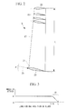
- Fig. 2 is a front view of the wind turbine blade 9.
- Fig. 2 also shows cross-sectional views at certain locations of the wind turbine blade 9.
- the wind turbine blade 9 is a hollow body whose cross-sectional shape is an airfoil shape.
- the airfoil shape of the wind turbine blade 9 is defined by a skin 17 formed of, for example, fiberglass reinforced plastic. The strength of the skin 17 is reinforced from the inside with a main girder etc.
- the wind turbine blade 9 has an angle-of-attack decreasing portion 19 at a blade tip 20 portion.
- the angle-of-attack decreasing portion 19 is configured such that an angle of attack, which is the angle that the chord 23 forms relative to a wind direction 25, decreases gradually from the angle of attack ⁇ at a blade root 21 side toward the blade tip 20.
- the angle-of-attack decreasing portion 19 is formed such that it is twisted so that the angle of the blade with respect to the wind inflow direction decreases gradually toward the blade tip 20; that is, a twist angle is applied to the blade tip portion.
- Fig. 3 shows changes in angle of attack in the blade longitudinal direction of the wind turbine blade 9.
- the length of the angle-of-attack decreasing portion 19 in the blade longitudinal direction is set in consideration of the influence on the performance of the blade and the noise reduction effect, which is here set at approximately 10% of the blade length L. It is preferable to set it within 20% in consideration of degradation in performance.
- the angle of attack at the blade tip 20 of the angle-of-attack decreasing portion 19 is set to, for example, 0° at a rotational speed (rated rotational speed) at which rated output power is generated.
- the angle of attack at the blade tip 20 is not limited to 0°; it may be set to a value other than 0° in consideration of other conditions other than noise.
- a value at which the boundary layer becomes the thinnest may be other than 0° depending on the airfoil (for example, with a camber etc.).
- the wind power generator 1 measures the wind direction with the anemoscope 15 during operation. Depending on the measurement result, the nacelle 5 rotates so that wind blows from the rotational axis direction of the rotor head 7. That is, wind blows against the wind turbine blade 9 in a fixed direction. When wind blows against the wind turbine blade 9, lift is generated in a direction intersecting the blade surface. Since this lift moves the wind turbine blade 9, the rotor head 7 rotates about the rotational axis. The rotational speed of the rotor head 7 is increased by the gearbox to drive the generator, thereby achieving power generation.
- the pitch angle of the wind turbine blade 9 is adjusted by rotating in the blade longitudinal direction depending on the wind speed measured by the anemometer 13. If the wind speed is low, the pitch angle is increased so as to increase an area that receives wind. When the wind speed exceeds a rotational speed at which rated output power can be obtained (rated rotational speed), the pitch angle is decreased to reduce the area that receives wind.
- the resistance that wind receives from the blade surface of the angle-of-attack decreasing portion 19 is smaller than that of one having the same angle of attack as the blade root 21 side, because the angle of attack at the angle-of-attack decreasing portion 19 is smaller than that at the blade root 21 side. Since this allows the wind to flow smoothly along the blade surface, the thickness of a boundary layer formed on the blade surface is smaller than one whose blade tip portion has the same angle of attack as the blade root 21 side. The decrease in thickness of the boundary layer can prevent the occurrence of a vortex at the trailing edge of the wind turbine blade 9, thus reducing noise.
- angle-of-attack decreasing portion 19 is provided at the tip portion of the wind turbine blade 9 at which high noise is generated due to the high moving speed, noise can be reduced effectively. This eliminates the need for decreasing the rotational speed to reduce the noise, which can prevent a degradation in performance, such as a degradation in power generation efficiency.
- the angle of attack at the angle-of-attack decreasing portion 19 is fixed. Therefore, even if the rotational speed changes, the mutual relationship is not changed. Therefore, the angle of attack of the angle-of-attack decreasing portion 19 always differs from the blade root 21 side irrespective of the rotational speed, which can reduce noise in a wide range of rotational speeds.
- the wind power generator 1 can reduce the occurrence of noise during operation. Since this can relax restrictions due to noise, the flexibility of the installation site can be ensured; for example, it can be installed in the vicinity of a residential district.
- Fig. 4 is a front view of the wind turbine blade 9.
- Fig. 5 is a side view of the wind turbine blade 9, showing a state at the rated rotational speed.
- Fig. 6 is a side view of the wind turbine blade 9, showing a halted state.
- the wind turbine blade 9 is provided with the angle-of-attack decreasing portion 19 at the tip portion thereof.
- the angle-of-attack decreasing portion 19 is formed, as shown in Fig. 6 , by being smoothly curved to a positive pressure surface 27 side so that the curve gradually increases from the blade surface of the blade root 21 side toward the blade tip 20.
- This curve is set so that, when the wind turbine blade 9 rotates at a predetermined rotational speed and is deformed due to wind, the angle-of-attack decreasing portion 19 becomes substantially an extension of the blade surface of the blade root 21 side; that is, the blade surface of the blade root 21 side becomes flush with the blade surface of the angle-of-attack decreasing portion 19, as shown in Fig. 5 .
- the angle-of-attack decreasing portion 19 at that time is sometimes denoted by reference numeral 19B.
- the angle-of-attack decreasing portion 19 in the halted state (that is, at production time) is sometimes denoted by reference numeral 19A.
- this embodiment can reduce noise at the rated rotational speed and can prevent a degradation in performance as compared with the wind turbine blade 9 that does not have the angle-of-attack decreasing portion 19.
- the present invention is not limited thereto; for example, the angle-of-attack decreasing portion 19 may be formed such that it is twisted so that the angle of attack becomes smaller than the angle of attack at the blade root 21 side.
- the present invention is not limited to the embodiments described above; various modifications can be made as appropriate without departing from the spirit thereof.
- the present invention may have a configuration having both the configuration of the first embodiment in which the angle of attack is gradually decreased with an increasing distance to the blade tip 20 of the wind turbine blade 9 and the configuration of the second embodiment that makes use of deformation during rotation.
Abstract
Description
- The present invention relates to a wind turbine blade and a wind power generator that generates power using the same.
- Wind power generators have problems of noise generated from blades. The main causes of blade-generated noise are a blade tip vortex and a turbulent-flow boundary layer generated on the blade surface.
It is thought that decreasing the rotational speed of a rotor is effective in reducing the noise level. Specifically, decreasing the rotational speed of the rotor decreases the inlet velocity of air to the blades, thereby allowing aerodynamic sound to be reduced. However, decreasing the rotational speed of the rotor has a problem of decreasing the power generation efficiency. - In particular, for reducing noise at a high-noise blade tip portion, for example, an approach disclosed in Patent Citation 1 has been proposed.
This prevents noise by curving or bending the blade tip portion on the blade surface toward the trailing edge of the blade (a so-called sweptback wing) and/or providing a small blade (a so-called winglet) that is bent toward a positive pressure surface so as to intersect the blade tip portion to thereby decrease the vortex at the blade tip portion. - Patent Citation 1: Japanese Translation of PCT International Application, Publication No.
2006-521483 - In recent years, wind power generators have been required to generate high power and have increased in size. Along with this, the rotor diameter, that is, the blade lengths of wind turbine blades, have been increased.
With the increase in blade length, the moving speed of blade tip portions increases. This increases noise generated, and therefore, a further noise reduction is required.
Moreover, because the influence of noise due to turbulent-flow boundary layers generated on blade surfaces in the vicinity of the blade tips is increased due to the increase in blade length, sufficient noise reduction cannot be expected with an approach that reduces noise only at the blade tip portions, as in Patent Citation 1. - The present invention is made in consideration of the circumstances described above, and it is an object thereof to provide a wind turbine blade that can reduce the thickness of the turbulent-flow boundary layer generated on the blade surface at the blade tip portion to prevent noise generated at the trailing edge portion effectively, as well as a wind power generator using the same.
- The present invention adopts the following solutions to solve the problems described above.
According to a first aspect of the present invention, there is provided a wind turbine blade having an airfoil shape in cross section, wherein an angle-of-attack decreasing portion that decreases an angle of attack during rotation at at least a predetermined rotational speed is provided over a predetermined range from a blade tip to a blade root side. - With the wind turbine blade according to this aspect, since the angle-of-attack decreasing portion decreases the angle of attack during rotation at at least the predetermined rotational speed over a predetermined range from the blade tip to the blade root side, the thickness of the boundary layer on the blade surface of the predetermined range from the blade tip to the blade root side can be decreased during operation.
The decrease in thickness of the boundary layer can prevent the occurrence of a vortex at the trailing edge of the blade, thus reducing noise.
Since the angle-of-attack decreasing portion is provided at the tip portion of the wind turbine blade at which high noise is generated, noise can be reduced effectively. This eliminates the need for decreasing the rotational speed to reduce the noise, which can prevent a degradation in performance, such as a degradation in power generation efficiency.
Given the same cross-sectional shape of the blade, the lift generated is decreased with a decrease in angle of attack; therefore, it is preferable to set the range in which the angle-of-attack decreasing portion is provided in consideration of the influence on the performance of the blade and the noise reduction effect. This range is set, for example, within 20% of the blade length, preferably, within 10%.
The predetermined rotational speed is set to, for example, a rotational speed at which the wind power generator outputs rated power, that is, a rated rotational speed. - In the above aspect, the angle-of-attack decreasing portion may be formed so that the angle of attack gradually decreases from the angle of attack of the blade root side toward the blade tip.
In other words, the angle-of-attack decreasing portion is formed such that it is twisted so that the angle of the blade with respect to the wind inflow direction decreases gradually toward the blade tip, that is, a twist angle is applied to the blade tip portion.
This makes the angle of attack of the angle-of-attack decreasing portion always differ from the blade root side irrespective of the rotational speed, which can reduce noise in a wide rotational speed range. - In the above aspect, the angle-of-attack decreasing portion may be formed so as to become substantially an extension of the blade surface of the blade root side during rotation at the predetermined rotational speed.
In other words, the surface of the angle-of-attack decreasing portion is formed to become substantially flush with the blade surface of the blade root side during rotation at the predetermined rotational speed. - When a blade rotates, the blade is deformed due to wind. This deformation becomes large at the tip portion of the blade. This deformation makes the angle of attack at the tip portion of the wind turbine blade larger than a design value, thus increasing noise.
With this configuration, when the blade rotates at the predetermined rotational speed and is deformed due to wind, the angle-of-attack decreasing portion is formed so as to become substantially an extension of the blade surface of the blade root side, that is, such that the blade surface of the blade root side becomes flush with the blade surface of the angle-of-attack decreasing portion, which therefore prevents the angle of attack of the angle-of-attack decreasing portion from becoming larger than the design value; in other words, it can decrease the angle of attack at the predetermined rotational speed as compared with a blade having no angle-of-attack decreasing portion.
This can reduce noise at the predetermined rotational speed and can prevent a degradation in performance - With the above configuration, it is preferable that the angle-of-attack decreasing portion be smoothly curved so that the curve gradually becomes sharp from the blade surface of the blade root side toward a positive pressure surface side.
- According to a second aspect of the present invention, there is provided a wind power generator that generates electricity using a wind turbine blade in which the occurrence of a vortex at the trailing edge of the blade during rotation at at least a predetermined rotational speed can be prevented.
- This allows the wind power generator to reduce the occurrence of noise during operation. Since this can relax restrictions due to noise, the flexibility of the installation site can be ensured; for example, it can be installed in the vicinity of a residential district.
- According to the present invention, since the angle-of-attack decreasing portion decreases the angle of attack during rotation at at least the predetermined rotational speed over the predetermined range from the blade tip to the blade root side, the occurrence of a vortex at the trailing edge of the blade can be prevented during operation, thus reducing noise.
Moreover, since the angle-of-attack decreasing portion is provided at the tip portion of the wind turbine blade at which high noise is generated, noise can be reduced effectively. This eliminates the need for decreasing the rotational speed to reduce the noise, which can prevent a degradation in performance, such as a degradation in power generation efficiency. -
- [
Fig. 1] Fig. 1 is a side view showing, in outline, the overall configuration of a wind power generator according to a first embodiment of the present invention. - [
Fig. 2] Fig. 2 is a front view of the wind turbine blade according to the first embodiment of the present invention. - [
Fig. 3] Fig. 3 is a graph showing changes in angle of attack of the wind turbine blade according to the first embodiment of the present invention. - [
Fig. 4] Fig. 4 is a front view of a wind turbine blade according to a second embodiment of the present invention. - [
Fig. 5] Fig. 5 is a side view of the wind turbine blade according to the second embodiment of the present invention, showing a state at the rated rotational speed. - [
Fig. 6] Fig. 6 is a side view of the wind turbine blade according to the second embodiment of the present invention, showing a halted state. -
- 1: wind power generator
- 9: wind turbine blade
- 19: angle-of-attack decreasing portion
- 20: blade tip
- 21: blade root
- 27: positive pressure surface
- A wind power generator 1 according to an embodiment of the present invention will be described hereinbelow based on the drawings.
Fig. 1 is a side view showing, in outline, the overall configuration of the wind power generator 1.
The wind power generator 1 includes, as shown inFig. 1 , a tower 3 that is vertically erected on a foundation 11; a nacelle 5 that is substantially horizontally mounted on the upper end of the tower 3 so as to be rotatable, with the tower 3 serving as the fulcrum; arotor head 7 mounted on the nacelle 5 so as to be rotatable about the substantially horizontal axis thereof; and a plurality ofwind turbine blades 9 that are mounted in a radiating pattern about the rotational axis of therotor head 7 so as to be rotatable about the blade longitudinal direction.
The force of wind blowing against thewind turbine blades 9 from the rotational axis direction of therotor head 7 is converted to motive power that rotates therotor head 7 about the rotational axis. - An
anemometer 13 that measures the wind speed value in the vicinity, aanemoscope 15 that measures the wind direction, and a lightning rod (not shown) are provided at appropriate locations of the outer peripheral surface (for example, at the top etc.) of the nacelle 5.
The nacelle 5 accommodates a generator connected to therotor head 7 via a gearbox coaxial therewith, both of which are not shown. That is, generator output power can be obtained from the generator by driving the generator while increasing the rotational speed of therotor head 7 with the gearbox. -
Fig. 2 is a front view of thewind turbine blade 9.Fig. 2 also shows cross-sectional views at certain locations of thewind turbine blade 9.
Thewind turbine blade 9 is a hollow body whose cross-sectional shape is an airfoil shape. The airfoil shape of thewind turbine blade 9 is defined by askin 17 formed of, for example, fiberglass reinforced plastic. The strength of theskin 17 is reinforced from the inside with a main girder etc. - The
wind turbine blade 9 has an angle-of-attack decreasing portion 19 at ablade tip 20 portion. The angle-of-attack decreasing portion 19 is configured such that an angle of attack, which is the angle that thechord 23 forms relative to awind direction 25, decreases gradually from the angle of attack α at ablade root 21 side toward theblade tip 20. In other words, the angle-of-attack decreasing portion 19 is formed such that it is twisted so that the angle of the blade with respect to the wind inflow direction decreases gradually toward theblade tip 20; that is, a twist angle is applied to the blade tip portion. -
Fig. 3 shows changes in angle of attack in the blade longitudinal direction of thewind turbine blade 9.
The length of the angle-of-attack decreasing portion 19 in the blade longitudinal direction is set in consideration of the influence on the performance of the blade and the noise reduction effect, which is here set at approximately 10% of the blade length L. It is preferable to set it within 20% in consideration of degradation in performance.
The angle of attack at theblade tip 20 of the angle-of-attack decreasing portion 19 is set to, for example, 0° at a rotational speed (rated rotational speed) at which rated output power is generated.
In addition, the angle of attack at theblade tip 20 is not limited to 0°; it may be set to a value other than 0° in consideration of other conditions other than noise.
A value at which the boundary layer becomes the thinnest may be other than 0° depending on the airfoil (for example, with a camber etc.). - The operational action of the thus-configured wind power generator 1 will be described.
The wind power generator 1 measures the wind direction with theanemoscope 15 during operation. Depending on the measurement result, the nacelle 5 rotates so that wind blows from the rotational axis direction of therotor head 7. That is, wind blows against thewind turbine blade 9 in a fixed direction.
When wind blows against thewind turbine blade 9, lift is generated in a direction intersecting the blade surface. Since this lift moves thewind turbine blade 9, therotor head 7 rotates about the rotational axis.
The rotational speed of therotor head 7 is increased by the gearbox to drive the generator, thereby achieving power generation. - The pitch angle of the
wind turbine blade 9 is adjusted by rotating in the blade longitudinal direction depending on the wind speed measured by theanemometer 13. If the wind speed is low, the pitch angle is increased so as to increase an area that receives wind. When the wind speed exceeds a rotational speed at which rated output power can be obtained (rated rotational speed), the pitch angle is decreased to reduce the area that receives wind. - At that time, for example, at the rated rotational speed, assuming that the moving speeds are equal, the resistance that wind receives from the blade surface of the angle-of-
attack decreasing portion 19 is smaller than that of one having the same angle of attack as theblade root 21 side, because the angle of attack at the angle-of-attack decreasing portion 19 is smaller than that at theblade root 21 side. Since this allows the wind to flow smoothly along the blade surface, the thickness of a boundary layer formed on the blade surface is smaller than one whose blade tip portion has the same angle of attack as theblade root 21 side.
The decrease in thickness of the boundary layer can prevent the occurrence of a vortex at the trailing edge of thewind turbine blade 9, thus reducing noise.
Since the angle-of-attack decreasing portion 19 is provided at the tip portion of thewind turbine blade 9 at which high noise is generated due to the high moving speed, noise can be reduced effectively. This eliminates the need for decreasing the rotational speed to reduce the noise, which can prevent a degradation in performance, such as a degradation in power generation efficiency. - The angle of attack at the angle-of-
attack decreasing portion 19 is fixed. Therefore, even if the rotational speed changes, the mutual relationship is not changed.
Therefore, the angle of attack of the angle-of-attack decreasing portion 19 always differs from theblade root 21 side irrespective of the rotational speed, which can reduce noise in a wide range of rotational speeds. - In this manner, the wind power generator 1 can reduce the occurrence of noise during operation. Since this can relax restrictions due to noise, the flexibility of the installation site can be ensured; for example, it can be installed in the vicinity of a residential district.
- Next, a second embodiment of the present invention will be described using
Fig. 4 to Fig. 6 .
This embodiment is the same as the first embodiment in basic configuration and differs only in the configuration of thewind turbine blade 9. Thus, in this embodiment, the differences will be described, and duplicated descriptions of the other parts will be omitted.
The same components as in the first embodiment are given the same reference numerals, and their detailed descriptions will be omitted.
Fig. 4 is a front view of thewind turbine blade 9.Fig. 5 is a side view of thewind turbine blade 9, showing a state at the rated rotational speed.Fig. 6 is a side view of thewind turbine blade 9, showing a halted state. - The
wind turbine blade 9 is provided with the angle-of-attack decreasing portion 19 at the tip portion thereof. The angle-of-attack decreasing portion 19 is formed, as shown inFig. 6 , by being smoothly curved to apositive pressure surface 27 side so that the curve gradually increases from the blade surface of theblade root 21 side toward theblade tip 20.
This curve is set so that, when thewind turbine blade 9 rotates at a predetermined rotational speed and is deformed due to wind, the angle-of-attack decreasing portion 19 becomes substantially an extension of the blade surface of theblade root 21 side; that is, the blade surface of theblade root 21 side becomes flush with the blade surface of the angle-of-attack decreasing portion 19, as shown inFig. 5 . The angle-of-attack decreasing portion 19 at that time is sometimes denoted byreference numeral 19B. The angle-of-attack decreasing portion 19 in the halted state (that is, at production time) is sometimes denoted byreference numeral 19A. - Since the operational action of the thus-configured wind power generator 1 is substantially the same as the first embodiment, duplicated descriptions will be omitted, and differences will be described.
When thewind turbine blade 9 rotates, thewind turbine blade 9 is deformed by a force due to the action of wind (lift and drag). This deformation increases at the blade tip portion of thewind turbine blade 9, that is, at the angle-of-attack decreasing portion 19.
When the rotational speed of thewind turbine blade 9 reaches the rated rotational speed, the angle-of-attack decreasing portion 19 changes from the angle-of-attack decreasing portion 19A in the halted state, shown inFig. 6 , to the state of the angle-of-attack decreasing portion 19B shown inFig. 5 . That is, since the angle-of-attack decreasing portion 19B becomes substantially the extension of the blade surface at theblade root 21 side, the angle of attack of the angle-of-attack decreasing portion 19B does not become larger than a design value. - That is, with a
wind turbine blade 9 that does not have the angle-of-attack decreasing portion 19, the angle of attack becomes larger than the design value at the tip portion due to the deformation, thus increasing noise; however, with thewind turbine blade 9 of this embodiment, the angle of attack at the rated rotational speed can be decreased as compared therewith.
Accordingly, this embodiment can reduce noise at the rated rotational speed and can prevent a degradation in performance as compared with thewind turbine blade 9 that does not have the angle-of-attack decreasing portion 19. - Although this embodiment is configured such that the angle-of-
attack decreasing portion 19 becomes substantially an extension of the blade surface at theblade root 21 side when the rated rotational speed is reached, the present invention is not limited thereto; for example, the angle-of-attack decreasing portion 19 may be formed such that it is twisted so that the angle of attack becomes smaller than the angle of attack at theblade root 21 side. - The present invention is not limited to the embodiments described above; various modifications can be made as appropriate without departing from the spirit thereof.
For example, the present invention may have a configuration having both the configuration of the first embodiment in which the angle of attack is gradually decreased with an increasing distance to theblade tip 20 of thewind turbine blade 9 and the configuration of the second embodiment that makes use of deformation during rotation.
Claims (5)
- A wind turbine blade having an airfoil shape in cross section, wherein
an angle-of-attack decreasing portion that decreases an angle of attack during rotation at at least a predetermined rotational speed is provided over a predetermined range from a blade tip to a blade root side. - The wind turbine blade according to Claim 1, wherein the angle-of-attack decreasing portion is formed so that the angle of attack gradually decreases from the angle of attack of the blade root side toward the blade tip.
- The wind turbine blade according to Claim 1 or 2, wherein the angle-of-attack decreasing portion is formed so as to become substantially an extension of the blade surface of the blade root side during rotation at the predetermined rotational speed.
- The wind turbine blade according to Claim 3, wherein the angle-of-attack decreasing portion is smoothly curved so that the curve gradually becomes sharp from the blade surface of the blade root side toward a positive pressure surface side.
- A wind power generator that generates electricity using the wind turbine blade according to one of Claims 1 to 4.
Applications Claiming Priority (1)
| Application Number | Priority Date | Filing Date | Title |
|---|---|---|---|
| PCT/JP2007/072352 WO2009066360A1 (en) | 2007-11-19 | 2007-11-19 | Windmill blade and wind power generator using same |
Publications (2)
| Publication Number | Publication Date |
|---|---|
| EP2187045A1 true EP2187045A1 (en) | 2010-05-19 |
| EP2187045A4 EP2187045A4 (en) | 2013-01-02 |
Family
ID=40667198
Family Applications (1)
| Application Number | Title | Priority Date | Filing Date |
|---|---|---|---|
| EP07832082A Withdrawn EP2187045A4 (en) | 2007-11-19 | 2007-11-19 | Windmill blade and wind power generator using same |
Country Status (10)
| Country | Link |
|---|---|
| US (1) | US8851857B2 (en) |
| EP (1) | EP2187045A4 (en) |
| JP (1) | JP5134629B2 (en) |
| KR (1) | KR101158705B1 (en) |
| CN (1) | CN101784790A (en) |
| AU (1) | AU2007361564B2 (en) |
| BR (1) | BRPI0722027A2 (en) |
| CA (1) | CA2697615A1 (en) |
| MX (1) | MX2010003322A (en) |
| WO (1) | WO2009066360A1 (en) |
Cited By (3)
| Publication number | Priority date | Publication date | Assignee | Title |
|---|---|---|---|---|
| CN102011710A (en) * | 2010-11-23 | 2011-04-13 | 南京航空航天大学 | Wind machine blade |
| WO2012003308A2 (en) * | 2010-07-01 | 2012-01-05 | E-Net, Llc | Wind turbine with extended blades |
| US8178987B2 (en) | 2009-05-20 | 2012-05-15 | E-Net, Llc | Wind turbine |
Families Citing this family (6)
| Publication number | Priority date | Publication date | Assignee | Title |
|---|---|---|---|---|
| CA2752705C (en) * | 2008-02-14 | 2017-12-12 | Daniel Farb | Shrouded turbine blade design |
| ES2357063B2 (en) * | 2009-10-06 | 2012-01-24 | Líneas Y Cables, S.A. | AEROGENERATOR PROTECTION SYSTEM AGAINST ATMOSPHERIC DOWNLOADS. |
| US9086053B2 (en) | 2012-03-30 | 2015-07-21 | General Electric Company | Enhanced wind turbine blade |
| KR101464354B1 (en) * | 2012-05-18 | 2014-11-21 | 절강 리닉스 모터 컴퍼니 리미티드 | Wind power generation equipment |
| US20150379408A1 (en) * | 2014-06-30 | 2015-12-31 | Microsoft Corporation | Using Sensor Information for Inferring and Forecasting Large-Scale Phenomena |
| CN109340042A (en) * | 2018-11-19 | 2019-02-15 | 内蒙古工业大学 | Turbine blade and its design method and solar chimney electricity generation system |
Citations (4)
| Publication number | Priority date | Publication date | Assignee | Title |
|---|---|---|---|---|
| US1802094A (en) * | 1926-01-19 | 1931-04-21 | Elisha N Fales | Turbine |
| WO1992001156A1 (en) * | 1990-07-11 | 1992-01-23 | Danregn Vindkraft A/S | A wing for a windmill |
| WO2004061298A2 (en) * | 2003-01-02 | 2004-07-22 | Aloys Wobben | Wind turbine rotor blade with reduced noise emission |
| NL1030111C1 (en) * | 2005-08-13 | 2005-12-19 | Composite Technology Ct B V | Wind turbine rotor blade, has profile designed so that is displaced in up down and axial directions relative to pitch axis |
Family Cites Families (14)
| Publication number | Priority date | Publication date | Assignee | Title |
|---|---|---|---|---|
| US4291235A (en) * | 1979-02-26 | 1981-09-22 | Bergey Jr Karl H | Windmill |
| JPS5622499U (en) * | 1979-07-27 | 1981-02-27 | ||
| JPS61190173A (en) | 1985-02-20 | 1986-08-23 | Yamaha Motor Co Ltd | Rotor blade construction for wind mill |
| US5181678A (en) * | 1991-02-04 | 1993-01-26 | Flex Foil Technology, Inc. | Flexible tailored elastic airfoil section |
| GB2265672B (en) * | 1992-03-18 | 1995-11-22 | Advanced Wind Turbines Inc | Wind turbines |
| ES2232959T3 (en) * | 1997-09-04 | 2005-06-01 | Lm Glasfiber A/S | WIND MILL ROTOR AND ASPAS FOR THE SAME. |
| DE19963086C1 (en) * | 1999-12-24 | 2001-06-28 | Aloys Wobben | Rotor blade for wind-turbine energy plant divided into 2 sections with different blade tip to wind velocity ratios |
| JP2002276535A (en) * | 2001-03-21 | 2002-09-25 | Kayaba Ind Co Ltd | Variable vane mechanism |
| DE10300284A1 (en) | 2003-01-02 | 2004-07-15 | Aloys Wobben | Turbine rotor blade for wind-powered energy plant has tip region curved or angled in direction of rotor blade trailing edge |
| DE10359299A1 (en) | 2003-12-17 | 2005-08-25 | Robert Bosch Gmbh | support element |
| JP2005291185A (en) | 2004-04-05 | 2005-10-20 | Mitsubishi Heavy Ind Ltd | Wind power generator |
| JP2006152864A (en) | 2004-11-26 | 2006-06-15 | Ishikawajima Harima Heavy Ind Co Ltd | Blade for wind power generator and wind power generation device having the same |
| US8128338B2 (en) * | 2004-11-30 | 2012-03-06 | Kabushiki Kaisha Bellsion | Propeller and horizontal-axis wind turbine |
| JP4970838B2 (en) | 2006-04-28 | 2012-07-11 | ソフィアエンジニアリング株式会社 | Windmill for small wind generator |
-
2007
- 2007-11-19 KR KR1020107003810A patent/KR101158705B1/en not_active IP Right Cessation
- 2007-11-19 CN CN200780100312A patent/CN101784790A/en active Pending
- 2007-11-19 US US12/674,849 patent/US8851857B2/en not_active Expired - Fee Related
- 2007-11-19 BR BRPI0722027-8A patent/BRPI0722027A2/en not_active IP Right Cessation
- 2007-11-19 AU AU2007361564A patent/AU2007361564B2/en not_active Ceased
- 2007-11-19 JP JP2009542419A patent/JP5134629B2/en not_active Expired - Fee Related
- 2007-11-19 WO PCT/JP2007/072352 patent/WO2009066360A1/en active Application Filing
- 2007-11-19 EP EP07832082A patent/EP2187045A4/en not_active Withdrawn
- 2007-11-19 CA CA2697615A patent/CA2697615A1/en not_active Abandoned
- 2007-11-19 MX MX2010003322A patent/MX2010003322A/en not_active Application Discontinuation
Patent Citations (4)
| Publication number | Priority date | Publication date | Assignee | Title |
|---|---|---|---|---|
| US1802094A (en) * | 1926-01-19 | 1931-04-21 | Elisha N Fales | Turbine |
| WO1992001156A1 (en) * | 1990-07-11 | 1992-01-23 | Danregn Vindkraft A/S | A wing for a windmill |
| WO2004061298A2 (en) * | 2003-01-02 | 2004-07-22 | Aloys Wobben | Wind turbine rotor blade with reduced noise emission |
| NL1030111C1 (en) * | 2005-08-13 | 2005-12-19 | Composite Technology Ct B V | Wind turbine rotor blade, has profile designed so that is displaced in up down and axial directions relative to pitch axis |
Non-Patent Citations (1)
| Title |
|---|
| See also references of WO2009066360A1 * |
Cited By (5)
| Publication number | Priority date | Publication date | Assignee | Title |
|---|---|---|---|---|
| US8178987B2 (en) | 2009-05-20 | 2012-05-15 | E-Net, Llc | Wind turbine |
| WO2012003308A2 (en) * | 2010-07-01 | 2012-01-05 | E-Net, Llc | Wind turbine with extended blades |
| WO2012003308A3 (en) * | 2010-07-01 | 2012-03-29 | E-Net, Llc | Wind turbine with extended blades |
| CN102011710A (en) * | 2010-11-23 | 2011-04-13 | 南京航空航天大学 | Wind machine blade |
| CN102011710B (en) * | 2010-11-23 | 2012-07-18 | 南京航空航天大学 | Wind machine blade |
Also Published As
| Publication number | Publication date |
|---|---|
| AU2007361564A1 (en) | 2009-05-28 |
| MX2010003322A (en) | 2010-06-08 |
| EP2187045A4 (en) | 2013-01-02 |
| KR20100047269A (en) | 2010-05-07 |
| AU2007361564B2 (en) | 2013-02-14 |
| KR101158705B1 (en) | 2012-06-22 |
| WO2009066360A1 (en) | 2009-05-28 |
| US8851857B2 (en) | 2014-10-07 |
| CA2697615A1 (en) | 2009-05-28 |
| JPWO2009066360A1 (en) | 2011-03-31 |
| CN101784790A (en) | 2010-07-21 |
| US20100213721A1 (en) | 2010-08-26 |
| JP5134629B2 (en) | 2013-01-30 |
| BRPI0722027A2 (en) | 2014-03-25 |
Similar Documents
| Publication | Publication Date | Title |
|---|---|---|
| US8932024B2 (en) | Wind turbine blade and wind power generator using the same | |
| US8851857B2 (en) | Wind turbine blade and wind power generator using the same | |
| EP2341245B1 (en) | Apparatus for increasing lift on wind turbine blade | |
| JP5479388B2 (en) | Wind turbine blade and wind power generator equipped with the same | |
| EP2107235A1 (en) | A wind turbine blade with an auxiliary airfoil | |
| US20110142676A1 (en) | Rotor blade assembly having an auxiliary blade | |
| EP2604856A1 (en) | Wind turbine blade, wind power generation device provided with same, and design method for wind turbine blade | |
| EP3037656B1 (en) | Rotor blade with vortex generators | |
| US20150132141A1 (en) | Rotor blade of a wind turbine | |
| EP3453872B1 (en) | Methods for mitigating noise during high wind speed conditions of wind turbines | |
| JP5433554B2 (en) | Wind turbine blade, wind power generator equipped with the wind turbine blade, and wind turbine blade design method | |
| US7854595B2 (en) | Wind turbine blade tip shapes | |
| EP3472456B1 (en) | Wind turbine blade with tip end serrations | |
| KR20130069812A (en) | Wind turbine blade, wind power generating device comprising same, and wind turbine blade design method | |
| JP5463386B2 (en) | Wind turbine blade and wind power generator using the same | |
| CN117469080A (en) | Rotor blade for a wind turbine and corresponding wind turbine | |
| WO2011091476A1 (en) | Wind turbine |
Legal Events
| Date | Code | Title | Description |
|---|---|---|---|
| PUAI | Public reference made under article 153(3) epc to a published international application that has entered the european phase |
Free format text: ORIGINAL CODE: 0009012 |
|
| 17P | Request for examination filed |
Effective date: 20100223 |
|
| AK | Designated contracting states |
Kind code of ref document: A1 Designated state(s): AT BE BG CH CY CZ DE DK EE ES FI FR GB GR HU IE IS IT LI LT LU LV MC MT NL PL PT RO SE SI SK TR |
|
| AX | Request for extension of the european patent |
Extension state: AL BA HR MK RS |
|
| DAX | Request for extension of the european patent (deleted) | ||
| A4 | Supplementary search report drawn up and despatched |
Effective date: 20121205 |
|
| RIC1 | Information provided on ipc code assigned before grant |
Ipc: F03D 1/06 20060101AFI20121129BHEP Ipc: F03D 11/00 20060101ALI20121129BHEP |
|
| 17Q | First examination report despatched |
Effective date: 20131113 |
|
| STAA | Information on the status of an ep patent application or granted ep patent |
Free format text: STATUS: THE APPLICATION IS DEEMED TO BE WITHDRAWN |
|
| 18D | Application deemed to be withdrawn |
Effective date: 20150203 |