EP2175132A1 - Wind power generator - Google Patents
Wind power generator Download PDFInfo
- Publication number
- EP2175132A1 EP2175132A1 EP08792462A EP08792462A EP2175132A1 EP 2175132 A1 EP2175132 A1 EP 2175132A1 EP 08792462 A EP08792462 A EP 08792462A EP 08792462 A EP08792462 A EP 08792462A EP 2175132 A1 EP2175132 A1 EP 2175132A1
- Authority
- EP
- European Patent Office
- Prior art keywords
- rotor head
- temperature
- nacelle
- wind turbine
- air
- Prior art date
- Legal status (The legal status is an assumption and is not a legal conclusion. Google has not performed a legal analysis and makes no representation as to the accuracy of the status listed.)
- Withdrawn
Links
Images


Classifications
-
- F—MECHANICAL ENGINEERING; LIGHTING; HEATING; WEAPONS; BLASTING
- F03—MACHINES OR ENGINES FOR LIQUIDS; WIND, SPRING, OR WEIGHT MOTORS; PRODUCING MECHANICAL POWER OR A REACTIVE PROPULSIVE THRUST, NOT OTHERWISE PROVIDED FOR
- F03D—WIND MOTORS
- F03D1/00—Wind motors with rotation axis substantially parallel to the air flow entering the rotor
- F03D1/06—Rotors
-
- F—MECHANICAL ENGINEERING; LIGHTING; HEATING; WEAPONS; BLASTING
- F03—MACHINES OR ENGINES FOR LIQUIDS; WIND, SPRING, OR WEIGHT MOTORS; PRODUCING MECHANICAL POWER OR A REACTIVE PROPULSIVE THRUST, NOT OTHERWISE PROVIDED FOR
- F03D—WIND MOTORS
- F03D80/00—Details, components or accessories not provided for in groups F03D1/00 - F03D17/00
- F03D80/60—Cooling or heating of wind motors
-
- F—MECHANICAL ENGINEERING; LIGHTING; HEATING; WEAPONS; BLASTING
- F05—INDEXING SCHEMES RELATING TO ENGINES OR PUMPS IN VARIOUS SUBCLASSES OF CLASSES F01-F04
- F05B—INDEXING SCHEME RELATING TO WIND, SPRING, WEIGHT, INERTIA OR LIKE MOTORS, TO MACHINES OR ENGINES FOR LIQUIDS COVERED BY SUBCLASSES F03B, F03D AND F03G
- F05B2260/00—Function
- F05B2260/20—Heat transfer, e.g. cooling
- F05B2260/205—Cooling fluid recirculation, i.e. after having cooled one or more components the cooling fluid is recovered and used elsewhere for other purposes
-
- F—MECHANICAL ENGINEERING; LIGHTING; HEATING; WEAPONS; BLASTING
- F05—INDEXING SCHEMES RELATING TO ENGINES OR PUMPS IN VARIOUS SUBCLASSES OF CLASSES F01-F04
- F05B—INDEXING SCHEME RELATING TO WIND, SPRING, WEIGHT, INERTIA OR LIKE MOTORS, TO MACHINES OR ENGINES FOR LIQUIDS COVERED BY SUBCLASSES F03B, F03D AND F03G
- F05B2260/00—Function
- F05B2260/60—Fluid transfer
- F05B2260/64—Aeration, ventilation, dehumidification or moisture removal of closed spaces
-
- F—MECHANICAL ENGINEERING; LIGHTING; HEATING; WEAPONS; BLASTING
- F05—INDEXING SCHEMES RELATING TO ENGINES OR PUMPS IN VARIOUS SUBCLASSES OF CLASSES F01-F04
- F05B—INDEXING SCHEME RELATING TO WIND, SPRING, WEIGHT, INERTIA OR LIKE MOTORS, TO MACHINES OR ENGINES FOR LIQUIDS COVERED BY SUBCLASSES F03B, F03D AND F03G
- F05B2270/00—Control
- F05B2270/30—Control parameters, e.g. input parameters
- F05B2270/303—Temperature
-
- Y—GENERAL TAGGING OF NEW TECHNOLOGICAL DEVELOPMENTS; GENERAL TAGGING OF CROSS-SECTIONAL TECHNOLOGIES SPANNING OVER SEVERAL SECTIONS OF THE IPC; TECHNICAL SUBJECTS COVERED BY FORMER USPC CROSS-REFERENCE ART COLLECTIONS [XRACs] AND DIGESTS
- Y02—TECHNOLOGIES OR APPLICATIONS FOR MITIGATION OR ADAPTATION AGAINST CLIMATE CHANGE
- Y02E—REDUCTION OF GREENHOUSE GAS [GHG] EMISSIONS, RELATED TO ENERGY GENERATION, TRANSMISSION OR DISTRIBUTION
- Y02E10/00—Energy generation through renewable energy sources
- Y02E10/70—Wind energy
- Y02E10/72—Wind turbines with rotation axis in wind direction
Definitions
- the present invention relates to a wind turbine generator that generates electricity using a wind turbine that converts natural wind energy to rotational power.
- a known wind turbine generator in the related art generates electricity using wind power, which is natural energy.
- This type of wind turbine generator is configured such that a nacelle mounted on a tower is provided with a rotor head equipped with wind turbine blades, a main shaft connected to the rotor head so as to rotate together therewith, a gear box connected to the main shaft that rotates by receiving wind power with the wind turbine blades, and a generator driven by the shaft output power of the gear box.
- the rotor head having the wind turbine blades that convert wind power to rotational power and the main shaft rotate to generate shaft output power
- the shaft output power which is increased in rotational speed through the gear box connected to the main shaft, is transmitted to the generator.
- power generation can be performed using the shaft output power obtained by converting wind power to rotational power as a driving source for the generator, that is, using wind power as motive power for the generator.
- the nacelle accommodates devices that generate heat during operation, for example, the gear box and generator. Therefore, a cooling structure in which an air intake port and an air exhaust port are formed is employed, and the interior of the nacelle is ventilated with a fan driven by a wind turbine to thereby prevent an increase in temperature therein.
- a cooling mechanism has been proposed that releases heat generated by a generator into the wind that has rotated the rotor with a plurality of fins provided on a frame that partitions the outer circumferential surface of the generator and outside air. This cooling mechanism does not need an intake port, an exhaust port, or a cooling fan.
- Patent Document 2 For example, refer to Patent Document 2
- the rotor head needs to adopt a sealing structure, which significantly increases the internal temperature due to an increase in the amount of heat generated in the internal devices.
- the rotor head also accommodates control devices etc. that are under severe installation temperature conditions. Therefore, sufficient temperature management is required, such as cooling the interior of the rotor head, to operate them normally.
- the internal temperature of the rotor head needs to satisfy the above-described low-temperature condition required for the control devices etc.
- the liquid such as hydraulic working oil and lubricating oil
- changes in the properties due to the low temperature become a problem, which requires temperature management, such as heating the interior of the rotor head.
- the present invention is made in consideration of the above-described circumstances, and it is an object of thereof to provide a wind turbine generator that is capable of temperature management of the interior of the rotor head.
- a wind turbine generator of the present invention is a wind turbine generator in which a driving and generating mechanism that is connected to a rotor head equipped with wind turbine blades is accommodated in a nacelle, and devices are disposed inside the rotor head, wherein a rotary joint is interposed in a driving shaft system that joins the rotor head and the nacelle, and fluid for regulating the temperature in the rotor head is supplied from the interior of the nacelle into the rotor head through the rotary joint.
- a rotary joint is interposed at an appropriate position of a driving shaft system that joins the rotor head and the nacelle, and fluid for regulating the temperature in the rotor head can be supplied from the interior of the non-rotating-side nacelle into the rotating-side rotor head through the rotary joint. Therefore, the internal temperature can be managed by cooling or heating as necessary.
- a rotary joint is interposed at an appropriate position of a driving shaft system that joins the rotor head and the nacelle, so that fluid for regulating the temperature in the rotor head can be supplied from the interior of the non-rotating-side nacelle into the rotating-side rotor head through the rotary joint. Therefore, the internal temperature of the rotor head can be managed by cooling or heating the interior as necessary. This allows control devices etc. mounted in the rotor head to be operated within a predetermined temperature range and can prevent changes in the properties of hydraulic working oil, lubricating oil, etc. at a low temperature, thus offering notable advantages in improving the reliability and durability of the wind turbine generator.
- a wind turbine generator 1 includes a tower 2 that is vertically erected on a base 6, a nacelle 3 mounted on the upper end of the tower 2, and a rotor head 4 mounted on the nacelle 3 so as to be rotatable about the substantially horizontal axis thereof.
- the rotor head 4 has a plurality of wind turbine blades 5 mounted radially about its rotation axis. As a result, the force of wind blowing against the wind turbine blades 5 from the direction of the rotation axis of the rotor head 4 is converted to motive power that rotates the rotor head 4 about the rotation axis.
- An anemoscope/anemometer 7 that measures the wind velocity value in the vicinity and a lightning rod 8 are provided at appropriate positions (for example, at the top etc.) of the outer peripheral surface of the nacelle 3.
- the nacelle 3 accommodates a driving and generating mechanism equipped with a generator 11 that is connected to the rotor head 4 via a gear box 10 coaxial therewith. That is, generator output power W is obtained from the generator 11 by driving the generator 11 while increasing the rotational speed of the rotor head 4 with the gear box 10.
- the above-described nacelle 3 has intake and exhaust ports for cooling the interior by ventilation.
- an intake port 12 opens at the lower front end of the nacelle 3, and an exhaust port 13a opens at the end of an exhaust duct 13 formed on the upper surface of the nacelle 3.
- a cooling fan 14 for ventilating and cooling the interior of the nacelle 3 is provided at an appropriate position in the nacelle 3, for example, in the exhaust duct 13, that is, in the vicinity of the exhaust port 13a.
- the above-described nacelle 3 accommodates a blowing unit 20 that regulates the internal temperature of the rotor head 4.
- the blowing unit 20 blows the air in the nacelle 3 by the operation of an internal fan 21 to regulate (cool or heat) the air temperature in the rotor head 4.
- the blowing unit 20 used here may be a single internal fan 21 as a blower capable of blowing the air in the nacelle 3, or alternatively, may be a combination with a heat pump or a heater used in, for example, an air conditioner, so that it can blow the air while actively regulating the air temperature in the nacelle 3.
- the blowing unit 20 in combination with a heat pump, although not shown, it is equipped with a compressor that sends refrigerant under pressure, a four-way valve that selects and switches the circulating direction of the refrigerant, a pair of heat exchangers that functions as a condenser or an evaporator in accordance with the circulating direction of the refrigerant, and a throttling mechanism including a capillary tube and an expansion valve.
- temperature regulation when the distinction between cooling and heating is unnecessary.
- the air (temperature-regulating fluid) in the nacelle 3 is supplied to the interior of the rotor head 4 through a temperature regulation pipe 22a, a rotary joint 30, and a temperature regulation pipe 22b by driving of the internal fan 21 in the blowing unit 20.
- the fluid is fed from the interior of the nacelle 3 into the rotor head 4 through a rotary joint 30 interposed, for example, in the drive shaft section connecting the gear box 10 and the generator 11, of the drive shaft system that joins the rotor head 4 and the nacelle 3.
- the temperature regulation pipes 22a and 22b through which the temperature-regulating air passes are connected from the fixed-side nacelle 3 to the rotating-side rotor head 4 via the rotary joint 30 interposed at an appropriate position of the driving shaft system that joins the rotor head 4 and the nacelle 3.
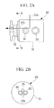
- the above-described rotary joint 30 is a joint that joins a fixed-side member and a rotating-side member to allow supply of fluid. As shown in Figs. 2A and 2B , for example, it includes a fixed-side main body 31 fixed to and supported by the nacelle 3 side and a rotating-side main body 32 joined to the rotor head 4 side, and fluid etc. that flows in pipes, such as the temperature regulation pipe 22a, joined to the fixed-side main body 31 is supplied to the non-rotating temperature regulation pipe 22b etc. passing through the rotating-side main body 32, inside the rotary joint 30.
- a hydraulic-oil feed pipe 33 that feeds the rotor head 4 with hydraulic working oil for controlling the pitch, a hydraulic-oil return pipe 34 that returns the hydraulic working oil to the nacelle 3 side, a wiring conduit tube 35 through which wires and cables for power supply and control necessary for various controls of the devices mounted in the rotor head 4 pass, and the temperature regulation pipe 22b that supplies the temperature-regulating air to the rotor head 4 pass through the rotary joint 30 shown in Fig. 2B .
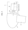
- Fig. 3 shows the connecting structure of the rotor head 4 and the nacelle 3, in which reference numeral 15 denotes the main shaft that transmits the rotation of the rotor head 4 to the gear box 10.
- temperature control of the interior of the rotary head 4 is performed as described below.
- This temperature control is part of the operational control executed by, for example, a nacelle control unit (not shown) mounted in the nacelle 3.
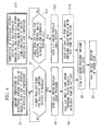
- the flowchart shown in Fig. 4 shows an example of the temperature control of the blowing unit 20 equipped with a heat pump to cool/heat the temperature-regulating air.
- the process proceeds to the next step S2.
- the outside temperature and the ambient temperature in this case are measured by temperature sensors (not shown) and are input to the nacelle control unit.
- step S2 it is determined whether the temperature measured by the temperature sensor for measuring the ambient temperature in the nacelle 3 is higher than a set point for the electrical control devices in the nacelle. If the result is YES, that is, the ambient temperature is higher than the set point, the process proceeds to step S3, where the blowing unit 20 is operated to send the air in the nacelle 3 under pressure as temperature-regulating air. In the next step S4, the air that is thus sent under pressure is cooled by the heat pump as necessary. That is, in cases such as when the air temperature in the nacelle 3 is higher than a predetermined value, the air in the nacelle 3 that the internal fan 21 sucked in as temperature-regulating air is cooled by the operation of the heat pump.
- step S4 is unnecessary.
- the temperature-regulating air (cooled air) cooled by the heat pump as necessary is sent under pressure from the blowing unit 20 into the rotor head 4 through the rotary joint 30.
- the interior of the rotor head 4 can be cooled by receiving low-temperature temperature-regulating air.
- the above-described control can reduce or prevent an increase in the temperature of the interior of the rotor head 4 by supplying cold air. Therefore, in particular, at a high outside temperature, the temperature of the interior of the rotor head 4 can be controlled by cooling so as not to exceed the upper limit for operation set for the control devices etc. mounted in the rotor head 4.
- step S11 when returning from a long period of halted operation at a low outside air temperature, that is, at an ambient temperature at which the temperature of the electrical control devices decreases and oils such as hydraulic working oil and lubricating oil become highly viscous, the process proceeds to the next step S12.
- step S12 if the temperature measured by the temperature sensor that measures the ambient temperature is lower than the set point for the electrical control devices in the nacelle or if it is lower than a set point for the oils such as hydraulic working oil, the process proceeds to the next step S13.
- step S13 the internal fan 21 of the blowing unit 20 is operated to send the air in the nacelle 3 under pressure.
- the temperature-regulating air that is thus sent under pressure is heated by a heating device, such as a heat pump or a heater, mounted in the blowing unit 20 as required. That is, in the case where the heating device is a heat pump, the blowing unit 20 executes the operation of heating the temperature-regulating air that is sucked from the interior of the nacelle 3 and is sent under pressure with the internal fan 21 by circulating the refrigerant in the direction opposite to that in the cooling in the step S4 described above.
- a heating device such as a heat pump or a heater
- the temperature-regulating air (warm air) heated by the heating device of the blowing unit 20 is sent under pressure into the rotor head 4 through the rotary joint 30.
- high-temperature temperature-regulating air is supplied into the rotor head 4, thereby allowing heating of the interior of the rotary head 4. Since the warm air is supplied into the rotor head 4 by the above-described control to increase the internal air temperature, temperature control can be performed by heating so that the temperature does not exceed the lower operating temperature limit set for the oils and the control devices installed in the rotor head 4, particularly as in the case of a low outside temperature.
- the rotary joint 30 is interposed at an appropriate position on the driving shaft that joins the rotor head 4 and the nacelle 3, so that the air for regulating the temperature in the rotor head can be supplied from the interior of the non-rotating side nacelle 3 into the rotating-side rotor head 4 through the rotary joint 30. Therefore, the internal temperature of the rotor head 4 can be managed by cooling or heating the interior as necessary. This allows the control devices etc. mounted in the rotor head 4 to be operated within a predetermined temperature range and, furthermore, can prevent changes in the properties of hydraulic working oil, lubricating oil, etc. at a low temperature, thus improving the reliability and durability of the wind turbine generator 1.
- the installation location of the blowing unit 20 can be set in the nacelle 3, many advantages can be offered; for example, the environment is better than that in the rotary head 4 and, in addition, its installation location can easily be ensured. In particular, installing the compressor of a heat pump, a heating heater, or the like, which consume much power, in the nacelle 3 can reduce the volume of a slip ring.
- the above-described embodiment is configured to supply temperature-regulating air into the rotor head 4 using the blowing unit 20, it is not limited thereto; another cooling source and heating source may be adopted.
- the fluid for use in temperature regulation is not limited to air, and another gas or liquid may be used.
- the present invention is not limited the above-described embodiment; for example, the position of the driving system in which the rotary joint is interposed, the type and configuration of the rotary joint, and the kind and number of fluids etc. that pass through the rotary joint can be modified as appropriate without departing from the spirit thereof.
Abstract
Description
- The present invention relates to a wind turbine generator that generates electricity using a wind turbine that converts natural wind energy to rotational power.
- A known wind turbine generator in the related art generates electricity using wind power, which is natural energy. This type of wind turbine generator is configured such that a nacelle mounted on a tower is provided with a rotor head equipped with wind turbine blades, a main shaft connected to the rotor head so as to rotate together therewith, a gear box connected to the main shaft that rotates by receiving wind power with the wind turbine blades, and a generator driven by the shaft output power of the gear box. In the thus-configured wind turbine generator, the rotor head having the wind turbine blades that convert wind power to rotational power and the main shaft rotate to generate shaft output power, and the shaft output power, which is increased in rotational speed through the gear box connected to the main shaft, is transmitted to the generator. Thus, power generation can be performed using the shaft output power obtained by converting wind power to rotational power as a driving source for the generator, that is, using wind power as motive power for the generator.
- In the conventional wind turbine generator described above, devices that involve heat generation, such as a pitch control unit, are accommodated in a rotating-side rotor head. In particular, with the increasing size of wind turbine blades recently, besides the increasing number of devices that generate a large amount of heat, there is also an increasing trend in the number of control devices that require temperature management of their installation environments, for example, the use of pitch control mechanisms that change the blade pitch quickly and accurately in response to fluctuations in wind speed.
- Also the nacelle accommodates devices that generate heat during operation, for example, the gear box and generator. Therefore, a cooling structure in which an air intake port and an air exhaust port are formed is employed, and the interior of the nacelle is ventilated with a fan driven by a wind turbine to thereby prevent an increase in temperature therein. (For example, refer to Patent Document 1)
For wind turbine generators, a cooling mechanism has been proposed that releases heat generated by a generator into the wind that has rotated the rotor with a plurality of fins provided on a frame that partitions the outer circumferential surface of the generator and outside air. This cooling mechanism does not need an intake port, an exhaust port, or a cooling fan. (For example, refer to Patent Document 2) - Patent Document 1: Japanese Unexamined Patent Application, Publication No.
Sho 58-65977 - Patent Document 2: Japanese Unexamined Patent Application, Publication No.
2002-13467 - As described above, in recent wind turbine generators, wind turbine blades are becoming larger to obtain high output power. Therefore, the motive power of a hydraulic mechanism etc. necessary for, for example, a device that controls the pitch of the wind turbine blades also increases, thus increasing the amount of heat generated therein. Accordingly, the temperature in the rotor head tends to rise as the wind turbine blades become large.
Since the interior of the rotor head, which is a rotating body, has a gap between it and the nacelle, which is a non-rotating body, there is a problem of intrusion of rain through the gap. Furthermore, if liquid in the hydraulic mechanism, such as working oil or lubricating oil, leaks in the rotary head, there is also a risk of the leaked liquid being splashed around the wind turbine generator due to the rotation of the rotor head. Therefore, the rotor head needs to adopt a sealing structure, which significantly increases the internal temperature due to an increase in the amount of heat generated in the internal devices. - However, the rotor head also accommodates control devices etc. that are under severe installation temperature conditions. Therefore, sufficient temperature management is required, such as cooling the interior of the rotor head, to operate them normally.
In the case where the installation environment of the wind turbine generator is a cold region, the internal temperature of the rotor head needs to satisfy the above-described low-temperature condition required for the control devices etc. Furthermore, also for the liquid, such as hydraulic working oil and lubricating oil, changes in the properties due to the low temperature become a problem, which requires temperature management, such as heating the interior of the rotor head. - Against such a backdrop, as wind turbine generators become larger, it becomes an important issue to manage the temperature of the interior of the rotor head by cooling or heating, thereby improving the reliability and durability of the wind turbine generators.
The present invention is made in consideration of the above-described circumstances, and it is an object of thereof to provide a wind turbine generator that is capable of temperature management of the interior of the rotor head. - The present invention adopts the following solutions to solve the above problems.
A wind turbine generator of the present invention is a wind turbine generator in which a driving and generating mechanism that is connected to a rotor head equipped with wind turbine blades is accommodated in a nacelle, and devices are disposed inside the rotor head, wherein a rotary joint is interposed in a driving shaft system that joins the rotor head and the nacelle, and fluid for regulating the temperature in the rotor head is supplied from the interior of the nacelle into the rotor head through the rotary joint. - With such a wind turbine generator, a rotary joint is interposed at an appropriate position of a driving shaft system that joins the rotor head and the nacelle, and fluid for regulating the temperature in the rotor head can be supplied from the interior of the non-rotating-side nacelle into the rotating-side rotor head through the rotary joint. Therefore, the internal temperature can be managed by cooling or heating as necessary.
- With the present invention described above, a rotary joint is interposed at an appropriate position of a driving shaft system that joins the rotor head and the nacelle, so that fluid for regulating the temperature in the rotor head can be supplied from the interior of the non-rotating-side nacelle into the rotating-side rotor head through the rotary joint. Therefore, the internal temperature of the rotor head can be managed by cooling or heating the interior as necessary. This allows control devices etc. mounted in the rotor head to be operated within a predetermined temperature range and can prevent changes in the properties of hydraulic working oil, lubricating oil, etc. at a low temperature, thus offering notable advantages in improving the reliability and durability of the wind turbine generator.
-
- [
Fig. 1] Fig. 1 is a sectional view of relevant parts showing an embodiment of a wind turbine generator according to the present invention. - [
Fig. 2A] Fig. 2A is a partial sectional plan view of a rotary joint shown inFig. 1 as a configuration example. - [
Fig. 2B] Fig. 2B is a cross-sectional view ofFig. 2A taken along line A-A. - [
Fig. 3] Fig. 3 is a diagram showing the connecting structure of a rotor head and a nacelle. - [
Fig. 4] Fig. 4 is a flowchart showing an example of cooling/heating control of the interior of the rotary head by a control unit. - [
Fig. 5] Fig. 5 is a diagram showing an example of the overall configuration of the wind turbine generator. Explanation of Reference Signs: -
- 1: wind
- turbine generator
- 2:
- tower
- 3:
- nacelle
- 4:
- rotor head
- 5:
- wind turbine blade
- 7:
- anemoscope/anemometer
- 10:
- gear box
- 11:
- generator
- 20:
- blowing unit
- 30:
- rotary joint
- An embodiment of a wind turbine generator according to the present invention will be described hereinbelow with reference to the drawings.
As shown inFig. 5 , awind turbine generator 1 includes atower 2 that is vertically erected on abase 6, anacelle 3 mounted on the upper end of thetower 2, and arotor head 4 mounted on thenacelle 3 so as to be rotatable about the substantially horizontal axis thereof.
Therotor head 4 has a plurality ofwind turbine blades 5 mounted radially about its rotation axis. As a result, the force of wind blowing against thewind turbine blades 5 from the direction of the rotation axis of therotor head 4 is converted to motive power that rotates therotor head 4 about the rotation axis. - An anemoscope/
anemometer 7 that measures the wind velocity value in the vicinity and a lightning rod 8 are provided at appropriate positions (for example, at the top etc.) of the outer peripheral surface of thenacelle 3.
As shown inFig. 1 , for example, thenacelle 3 accommodates a driving and generating mechanism equipped with agenerator 11 that is connected to therotor head 4 via agear box 10 coaxial therewith. That is, generator output power W is obtained from thegenerator 11 by driving thegenerator 11 while increasing the rotational speed of therotor head 4 with thegear box 10. - The above-described
nacelle 3 has intake and exhaust ports for cooling the interior by ventilation. In the illustrated configuration example, anintake port 12 opens at the lower front end of thenacelle 3, and anexhaust port 13a opens at the end of anexhaust duct 13 formed on the upper surface of thenacelle 3.
A coolingfan 14 for ventilating and cooling the interior of thenacelle 3 is provided at an appropriate position in thenacelle 3, for example, in theexhaust duct 13, that is, in the vicinity of theexhaust port 13a. By operating the coolingfan 14, outside air is introduced into thenacelle 3 through theair intake port 12, and the outside air passes through necessary portions in thenacelle 3 to ventilate and cool the interior, thereafter passes through the coolingfan 14, and flows out through theexhaust port 13a. - The above-described
nacelle 3 accommodates ablowing unit 20 that regulates the internal temperature of therotor head 4. The blowingunit 20 blows the air in thenacelle 3 by the operation of aninternal fan 21 to regulate (cool or heat) the air temperature in therotor head 4.
The blowingunit 20 used here may be a singleinternal fan 21 as a blower capable of blowing the air in thenacelle 3, or alternatively, may be a combination with a heat pump or a heater used in, for example, an air conditioner, so that it can blow the air while actively regulating the air temperature in thenacelle 3. That is, in the case of the blowingunit 20 in combination with a heat pump, although not shown, it is equipped with a compressor that sends refrigerant under pressure, a four-way valve that selects and switches the circulating direction of the refrigerant, a pair of heat exchangers that functions as a condenser or an evaporator in accordance with the circulating direction of the refrigerant, and a throttling mechanism including a capillary tube and an expansion valve.
In the description below, the whole operation for regulating the temperature of the air in thenacelle 3 by cooling or heating is generically referred to as "temperature regulation" when the distinction between cooling and heating is unnecessary. - The air (temperature-regulating fluid) in the
nacelle 3 is supplied to the interior of therotor head 4 through atemperature regulation pipe 22a, a rotary joint 30, and atemperature regulation pipe 22b by driving of theinternal fan 21 in theblowing unit 20.
The fluid is fed from the interior of thenacelle 3 into therotor head 4 through a rotary joint 30 interposed, for example, in the drive shaft section connecting thegear box 10 and thegenerator 11, of the drive shaft system that joins therotor head 4 and thenacelle 3. That is, thetemperature regulation pipes side nacelle 3 to the rotating-side rotor head 4 via the rotary joint 30 interposed at an appropriate position of the driving shaft system that joins therotor head 4 and thenacelle 3. - The above-described rotary joint 30 is a joint that joins a fixed-side member and a rotating-side member to allow supply of fluid. As shown in
Figs. 2A and 2B , for example, it includes a fixed-sidemain body 31 fixed to and supported by thenacelle 3 side and a rotating-sidemain body 32 joined to therotor head 4 side, and fluid etc. that flows in pipes, such as thetemperature regulation pipe 22a, joined to the fixed-sidemain body 31 is supplied to the non-rotatingtemperature regulation pipe 22b etc. passing through the rotating-sidemain body 32, inside the rotary joint 30. A hydraulic-oil feed pipe 33 that feeds therotor head 4 with hydraulic working oil for controlling the pitch, a hydraulic-oil return pipe 34 that returns the hydraulic working oil to thenacelle 3 side, awiring conduit tube 35 through which wires and cables for power supply and control necessary for various controls of the devices mounted in therotor head 4 pass, and thetemperature regulation pipe 22b that supplies the temperature-regulating air to therotor head 4 pass through the rotary joint 30 shown inFig. 2B .
Fig. 3 shows the connecting structure of therotor head 4 and thenacelle 3, in whichreference numeral 15 denotes the main shaft that transmits the rotation of therotor head 4 to thegear box 10. - In the
wind turbine generator 1 with the above-described configuration, temperature control of the interior of therotary head 4 is performed as described below. This temperature control is part of the operational control executed by, for example, a nacelle control unit (not shown) mounted in thenacelle 3.
The flowchart shown inFig. 4 shows an example of the temperature control of the blowingunit 20 equipped with a heat pump to cool/heat the temperature-regulating air. In thefirst step 31, if the ambient temperature of the electrical control devices mounted in thenacelle 3 rises due to an increase in outside air temperature, the process proceeds to the next step S2. The outside temperature and the ambient temperature in this case are measured by temperature sensors (not shown) and are input to the nacelle control unit. - In step S2, it is determined whether the temperature measured by the temperature sensor for measuring the ambient temperature in the
nacelle 3 is higher than a set point for the electrical control devices in the nacelle. If the result is YES, that is, the ambient temperature is higher than the set point, the process proceeds to step S3, where the blowingunit 20 is operated to send the air in thenacelle 3 under pressure as temperature-regulating air.
In the next step S4, the air that is thus sent under pressure is cooled by the heat pump as necessary. That is, in cases such as when the air temperature in thenacelle 3 is higher than a predetermined value, the air in thenacelle 3 that theinternal fan 21 sucked in as temperature-regulating air is cooled by the operation of the heat pump. In cases such as when the temperature in thenacelle 3 is lower than the predetermined value or when no heat pump is provided, the air in thenacelle 3 may be sent under pressure to therotor head 4 without being processed. In such a case, step S4 is unnecessary. - In the next step S5, the temperature-regulating air (cooled air) cooled by the heat pump as necessary is sent under pressure from the blowing
unit 20 into therotor head 4 through the rotary joint 30. As a result, in the next step S6, the interior of therotor head 4 can be cooled by receiving low-temperature temperature-regulating air.
The above-described control can reduce or prevent an increase in the temperature of the interior of therotor head 4 by supplying cold air. Therefore, in particular, at a high outside temperature, the temperature of the interior of therotor head 4 can be controlled by cooling so as not to exceed the upper limit for operation set for the control devices etc. mounted in therotor head 4. For the control in this case, it is assumed that the interior of thenacelle 3 and the interior of therotor head 4 are at substantially the same temperature. However, when there is a difference in internal temperature between thenacelle 3 and therotor head 4, it is desirable to measure not only the temperature in thenacelle 3 but also the temperature in therotor head 4. - On the other hand, in step S11, when returning from a long period of halted operation at a low outside air temperature, that is, at an ambient temperature at which the temperature of the electrical control devices decreases and oils such as hydraulic working oil and lubricating oil become highly viscous, the process proceeds to the next step S12.
In step S12, if the temperature measured by the temperature sensor that measures the ambient temperature is lower than the set point for the electrical control devices in the nacelle or if it is lower than a set point for the oils such as hydraulic working oil, the process proceeds to the next step S13. In step S13, theinternal fan 21 of the blowingunit 20 is operated to send the air in thenacelle 3 under pressure.
In the next step S14, the temperature-regulating air that is thus sent under pressure is heated by a heating device, such as a heat pump or a heater, mounted in theblowing unit 20 as required. That is, in the case where the heating device is a heat pump, the blowingunit 20 executes the operation of heating the temperature-regulating air that is sucked from the interior of thenacelle 3 and is sent under pressure with theinternal fan 21 by circulating the refrigerant in the direction opposite to that in the cooling in the step S4 described above. - In the next step S5, the temperature-regulating air (warm air) heated by the heating device of the blowing
unit 20 is sent under pressure into therotor head 4 through the rotary joint 30. As a result, in the next step S6, high-temperature temperature-regulating air is supplied into therotor head 4, thereby allowing heating of the interior of therotary head 4.
Since the warm air is supplied into therotor head 4 by the above-described control to increase the internal air temperature, temperature control can be performed by heating so that the temperature does not exceed the lower operating temperature limit set for the oils and the control devices installed in therotor head 4, particularly as in the case of a low outside temperature. - Since such temperature control allows temperature management of the interior of the
rotor head 4, a nearly sealed structure having a minimum gap for ventilation and cooling can be employed, thus solving the problem of rainwater intrusion through the gap. Furthermore, even if liquid, such as working oil or lubricating oil, in the hydraulic mechanism leaks into therotor head 4, the leaked liquid is not splashed around thewind turbine generator 1 due to the rotation of therotor head 4. - In this way, according to the present invention described above, the rotary joint 30 is interposed at an appropriate position on the driving shaft that joins the
rotor head 4 and thenacelle 3, so that the air for regulating the temperature in the rotor head can be supplied from the interior of thenon-rotating side nacelle 3 into the rotating-side rotor head 4 through the rotary joint 30. Therefore, the internal temperature of therotor head 4 can be managed by cooling or heating the interior as necessary. This allows the control devices etc. mounted in therotor head 4 to be operated within a predetermined temperature range and, furthermore, can prevent changes in the properties of hydraulic working oil, lubricating oil, etc. at a low temperature, thus improving the reliability and durability of thewind turbine generator 1.
Furthermore, since the installation location of the blowingunit 20 can be set in thenacelle 3, many advantages can be offered; for example, the environment is better than that in therotary head 4 and, in addition, its installation location can easily be ensured. In particular, installing the compressor of a heat pump, a heating heater, or the like, which consume much power, in thenacelle 3 can reduce the volume of a slip ring. - Although the above-described embodiment is configured to supply temperature-regulating air into the
rotor head 4 using theblowing unit 20, it is not limited thereto; another cooling source and heating source may be adopted. The fluid for use in temperature regulation is not limited to air, and another gas or liquid may be used.
The present invention is not limited the above-described embodiment; for example, the position of the driving system in which the rotary joint is interposed, the type and configuration of the rotary joint, and the kind and number of fluids etc. that pass through the rotary joint can be modified as appropriate without departing from the spirit thereof.
Claims (1)
- A wind turbine generator in which a driving and generating mechanism that is connected to a rotor head equipped with wind turbine blades is accommodated in a nacelle, and devices are disposed inside the rotor head, wherein
a rotary joint is interposed in a driving shaft system that joins the rotor head and the nacelle, and fluid for regulating the temperature in the rotor head is supplied from the interior of the nacelle into the rotor head through the rotary joint.
Applications Claiming Priority (2)
| Application Number | Priority Date | Filing Date | Title |
|---|---|---|---|
| JP2007302626A JP4796039B2 (en) | 2007-11-22 | 2007-11-22 | Wind power generator |
| PCT/JP2008/064581 WO2009066491A1 (en) | 2007-11-22 | 2008-08-14 | Wind power generator |
Publications (2)
| Publication Number | Publication Date |
|---|---|
| EP2175132A1 true EP2175132A1 (en) | 2010-04-14 |
| EP2175132A4 EP2175132A4 (en) | 2013-07-03 |
Family
ID=40667322
Family Applications (1)
| Application Number | Title | Priority Date | Filing Date |
|---|---|---|---|
| EP08792462.7A Withdrawn EP2175132A4 (en) | 2007-11-22 | 2008-08-14 | Wind power generator |
Country Status (9)
| Country | Link |
|---|---|
| US (1) | US8322985B2 (en) |
| EP (1) | EP2175132A4 (en) |
| JP (1) | JP4796039B2 (en) |
| KR (1) | KR101101728B1 (en) |
| CN (1) | CN101641520A (en) |
| AU (1) | AU2008320936B2 (en) |
| CA (1) | CA2670411C (en) |
| TW (1) | TW200925410A (en) |
| WO (1) | WO2009066491A1 (en) |
Cited By (4)
| Publication number | Priority date | Publication date | Assignee | Title |
|---|---|---|---|---|
| EP2796712A1 (en) * | 2013-04-26 | 2014-10-29 | Mitsubishi Heavy Industries, Ltd. | Wind turbine generator and method for cooling rotor hub of wind turbine generator |
| US8992170B2 (en) | 2010-12-20 | 2015-03-31 | Siemens Aktiengesellschaft | Wind turbine, method of control of a wind turbine and air-conditioning system |
| US9243611B2 (en) | 2009-09-18 | 2016-01-26 | Hanjun Song | Vertical axis wind turbine blade and its wind rotor |
| EP2302214B2 (en) † | 2009-09-25 | 2018-07-11 | General Electric Company | Method and system for cooling a wind turbine structure |
Families Citing this family (18)
| Publication number | Priority date | Publication date | Assignee | Title |
|---|---|---|---|---|
| DE102007054215A1 (en) * | 2007-11-12 | 2009-05-20 | Repower Systems Ag | Wind energy plant with heating device |
| US8082748B2 (en) * | 2009-07-08 | 2011-12-27 | Mitsubishi Heavy Industries, Ltd. | Wind turbine generator |
| WO2011004482A1 (en) * | 2009-07-09 | 2011-01-13 | 三菱重工業株式会社 | Wind power generator |
| US20110103950A1 (en) * | 2009-11-04 | 2011-05-05 | General Electric Company | System and method for providing a controlled flow of fluid to or from a wind turbine blade surface |
| CN102213188B (en) * | 2010-04-01 | 2016-10-05 | 上海电气风能装备有限公司 | Dehumidify desalination pressure-fired system in marine and intertidal belt wind generator group cabin |
| DE102010040917A1 (en) | 2010-09-16 | 2012-03-22 | Aloys Wobben | Magnus rotor |
| DE102010040911A1 (en) * | 2010-09-16 | 2012-03-22 | Aloys Wobben | Magnus rotor |
| KR101284867B1 (en) * | 2010-12-03 | 2013-07-09 | 삼성중공업 주식회사 | System for controlling the temperature of gear box of wind turbine and method using the same |
| JP5211244B2 (en) * | 2011-01-28 | 2013-06-12 | 三菱重工業株式会社 | Wind power generator |
| KR20120139667A (en) * | 2011-04-05 | 2012-12-27 | 미츠비시 쥬고교 가부시키가이샤 | Renewable energy type generating apparatus |
| CN102280974B (en) * | 2011-06-03 | 2014-05-07 | 江苏金风科技有限公司 | Cooling equipment and cooling method for wind-driven generator |
| KR101394708B1 (en) * | 2012-02-01 | 2014-05-16 | 전북대학교산학협력단 | Cooling System of Wind Generating Gearbox |
| JP5864307B2 (en) * | 2012-03-02 | 2016-02-17 | 株式会社日立製作所 | Downwind rotor type wind power generator |
| JP6198267B2 (en) * | 2012-07-17 | 2017-09-20 | 株式会社Ihi検査計測 | Windmill |
| DK2806542T3 (en) * | 2013-05-22 | 2016-12-19 | Siemens Ag | Airflow Control Device |
| EP2990644A1 (en) * | 2014-08-29 | 2016-03-02 | Siemens Aktiengesellschaft | Wind power assembly |
| CN104810997B (en) * | 2015-04-15 | 2017-03-01 | 新疆金风科技股份有限公司 | Permanent magnet direct-driving aerogenerator system and its collaborative drying control method of sealing |
| CN112780506B (en) * | 2021-03-02 | 2022-06-10 | 湖南常友环保科技有限公司 | Lightning-proof cabin cover assembly of wind driven generator |
Citations (3)
| Publication number | Priority date | Publication date | Assignee | Title |
|---|---|---|---|---|
| GB2071779A (en) * | 1980-03-17 | 1981-09-23 | United Technologies Corp | Wind turbine blade pitch adjustment system |
| JPH0633868A (en) * | 1992-07-16 | 1994-02-08 | Kubota Corp | Atomizing device utilizing windmill |
| JP2003343417A (en) * | 2002-05-27 | 2003-12-03 | Fuji Heavy Ind Ltd | Windmill |
Family Cites Families (23)
| Publication number | Priority date | Publication date | Assignee | Title |
|---|---|---|---|---|
| DE842330C (en) * | 1949-01-01 | 1952-06-26 | Helmut Dipl-Ing Voigt | Wind power plant |
| JPS5865977A (en) | 1981-10-14 | 1983-04-19 | Hitachi Ltd | Cooling mechanism for wind power generator |
| SE455629B (en) * | 1986-11-25 | 1988-07-25 | Flygt Ab | rotary joint |
| JPH0664895A (en) * | 1992-08-18 | 1994-03-08 | Hitachi Constr Mach Co Ltd | Cooling device for winch |
| DE19802574A1 (en) * | 1998-01-23 | 1999-03-11 | Siemens Ag | Wind power generator plant |
| BR0012432A (en) * | 1999-07-14 | 2002-04-02 | Aloys Wobben | Wind power installation, and, use of a tower from a wind power installation |
| US6278197B1 (en) * | 2000-02-05 | 2001-08-21 | Kari Appa | Contra-rotating wind turbine system |
| JP3989693B2 (en) | 2000-04-28 | 2007-10-10 | 三菱電機株式会社 | Wind power generator |
| US6492743B1 (en) * | 2001-06-28 | 2002-12-10 | Kari Appa | Jet assisted hybrid wind turbine system |
| KR100492461B1 (en) * | 2002-06-22 | 2005-05-31 | 학교법인 인하학원 | Method for removing heavy metals using O-polysaccharide |
| JP2004025676A (en) * | 2002-06-26 | 2004-01-29 | Mitsubishi Heavy Ind Ltd | Pasting roll of single facer |
| ITMI20021439A1 (en) * | 2002-06-28 | 2003-12-29 | High Technology Invest Bv | HIGH ENERGY EFFICIENCY WIND GENERATION PLANT |
| KR20040011045A (en) * | 2002-07-26 | 2004-02-05 | 삼성에스디에스 주식회사 | ASP constructing system and method for building facilities management |
| ITTO20020908A1 (en) * | 2002-10-17 | 2004-04-18 | Lorenzo Battisti | ANTI-ICE SYSTEM FOR WIND SYSTEMS. |
| JP2004293527A (en) * | 2003-03-28 | 2004-10-21 | Ebara Corp | Windmill device and wind power generation device |
| JP2005036727A (en) * | 2003-07-15 | 2005-02-10 | Ebara Corp | Anemometer and wind power generation device |
| TWM242587U (en) | 2003-08-22 | 2004-09-01 | Jin-Yi Chen | Improved structure for turbine type wind power generation device |
| JP2005069082A (en) * | 2003-08-22 | 2005-03-17 | Fuji Heavy Ind Ltd | Temperature controller of windmill |
| TWM255332U (en) | 2004-04-20 | 2005-01-11 | Wei-Min Wang | An auxiliary power generating apparatus for a geyser |
| KR200400645Y1 (en) | 2005-08-17 | 2005-11-08 | 최영구 | Windmill for a wind power generator |
| US8029239B2 (en) * | 2005-11-18 | 2011-10-04 | General Electric Company | Rotor for a wind energy turbine and method for controlling the temperature inside a rotor hub |
| KR200411045Y1 (en) | 2005-12-28 | 2006-03-15 | 라은건설 (주) | Aerogenerator |
| JP4738206B2 (en) * | 2006-02-28 | 2011-08-03 | 三菱重工業株式会社 | Wind power generation system and control method thereof |
-
2007
- 2007-11-22 JP JP2007302626A patent/JP4796039B2/en active Active
-
2008
- 2008-08-14 EP EP08792462.7A patent/EP2175132A4/en not_active Withdrawn
- 2008-08-14 AU AU2008320936A patent/AU2008320936B2/en not_active Ceased
- 2008-08-14 KR KR1020097010947A patent/KR101101728B1/en not_active IP Right Cessation
- 2008-08-14 WO PCT/JP2008/064581 patent/WO2009066491A1/en active Application Filing
- 2008-08-14 US US12/515,772 patent/US8322985B2/en active Active
- 2008-08-14 CN CN200880001208A patent/CN101641520A/en active Pending
- 2008-08-14 CA CA2670411A patent/CA2670411C/en not_active Expired - Fee Related
- 2008-08-26 TW TW097132550A patent/TW200925410A/en not_active IP Right Cessation
Patent Citations (3)
| Publication number | Priority date | Publication date | Assignee | Title |
|---|---|---|---|---|
| GB2071779A (en) * | 1980-03-17 | 1981-09-23 | United Technologies Corp | Wind turbine blade pitch adjustment system |
| JPH0633868A (en) * | 1992-07-16 | 1994-02-08 | Kubota Corp | Atomizing device utilizing windmill |
| JP2003343417A (en) * | 2002-05-27 | 2003-12-03 | Fuji Heavy Ind Ltd | Windmill |
Non-Patent Citations (1)
| Title |
|---|
| See also references of WO2009066491A1 * |
Cited By (5)
| Publication number | Priority date | Publication date | Assignee | Title |
|---|---|---|---|---|
| US9243611B2 (en) | 2009-09-18 | 2016-01-26 | Hanjun Song | Vertical axis wind turbine blade and its wind rotor |
| EP2302214B2 (en) † | 2009-09-25 | 2018-07-11 | General Electric Company | Method and system for cooling a wind turbine structure |
| US8992170B2 (en) | 2010-12-20 | 2015-03-31 | Siemens Aktiengesellschaft | Wind turbine, method of control of a wind turbine and air-conditioning system |
| EP2466128B2 (en) † | 2010-12-20 | 2017-06-28 | Siemens Aktiengesellschaft | Wind turbine and method of control of a wind turbine |
| EP2796712A1 (en) * | 2013-04-26 | 2014-10-29 | Mitsubishi Heavy Industries, Ltd. | Wind turbine generator and method for cooling rotor hub of wind turbine generator |
Also Published As
| Publication number | Publication date |
|---|---|
| US20110012362A1 (en) | 2011-01-20 |
| JP2009127505A (en) | 2009-06-11 |
| KR101101728B1 (en) | 2012-01-05 |
| JP4796039B2 (en) | 2011-10-19 |
| KR20090083417A (en) | 2009-08-03 |
| TWI354062B (en) | 2011-12-11 |
| AU2008320936B2 (en) | 2011-04-28 |
| AU2008320936A1 (en) | 2009-07-02 |
| CN101641520A (en) | 2010-02-03 |
| WO2009066491A1 (en) | 2009-05-28 |
| US8322985B2 (en) | 2012-12-04 |
| CA2670411C (en) | 2012-01-03 |
| EP2175132A4 (en) | 2013-07-03 |
| TW200925410A (en) | 2009-06-16 |
| CA2670411A1 (en) | 2009-05-28 |
Similar Documents
| Publication | Publication Date | Title |
|---|---|---|
| CA2670411C (en) | Wind turbine generator | |
| EP2148089B1 (en) | Wind-driven generator | |
| US7997855B2 (en) | Lubrication heating system and wind turbine incorporating same | |
| US20090200114A1 (en) | Thermal management system and wind turbine incorporating same | |
| US20100109326A1 (en) | Fan unit for wind power generator and wind power generator | |
| US8052383B2 (en) | Wind turbine, a method for controlling the temperature of fluid flowing in a first temperature control system of a wind turbine and use thereof | |
| EP2163761B1 (en) | Wind turbine comprising a heating and cooling system | |
| EP2453135B1 (en) | Wind power generator | |
| US11111905B2 (en) | Wind turbine and a method for operating a wind turbine | |
| KR101928791B1 (en) | Direct drive wind turbine with a thermal control system | |
| EP2375065A1 (en) | Wind driven generator | |
| JP4814608B2 (en) | Windmill | |
| JP2009185641A (en) | Wind power generator | |
| JP4848398B2 (en) | Wind power generator | |
| CN104565327A (en) | Lubrication and cooling system for gear case | |
| CN105863953B (en) | Wind driven generator blade, wind driven generator heat dissipation device and wind driven generator set | |
| CN112377377B (en) | Thermal cycle device of wind driven generator and wind driven generator | |
| US20240060477A1 (en) | Method for operating a wind turbine, cooling system and wind turbine |
Legal Events
| Date | Code | Title | Description |
|---|---|---|---|
| PUAI | Public reference made under article 153(3) epc to a published international application that has entered the european phase |
Free format text: ORIGINAL CODE: 0009012 |
|
| 17P | Request for examination filed |
Effective date: 20090520 |
|
| AK | Designated contracting states |
Kind code of ref document: A1 Designated state(s): AT BE BG CH CY CZ DE DK EE ES FI FR GB GR HR HU IE IS IT LI LT LU LV MC MT NL NO PL PT RO SE SI SK TR |
|
| AX | Request for extension of the european patent |
Extension state: AL BA MK RS |
|
| DAX | Request for extension of the european patent (deleted) | ||
| A4 | Supplementary search report drawn up and despatched |
Effective date: 20130605 |
|
| RIC1 | Information provided on ipc code assigned before grant |
Ipc: F03D 1/06 20060101ALI20130529BHEP Ipc: F03D 11/00 20060101AFI20130529BHEP |
|
| STAA | Information on the status of an ep patent application or granted ep patent |
Free format text: STATUS: THE APPLICATION HAS BEEN WITHDRAWN |
|
| 18W | Application withdrawn |
Effective date: 20130529 |